US10931190B2 - Systems and methods for mitigating harmonics in electrical systems by using active and passive filtering techniques - Google Patents
Systems and methods for mitigating harmonics in electrical systems by using active and passive filtering techniques Download PDFInfo
- Publication number
- US10931190B2 US10931190B2 US15/333,177 US201615333177A US10931190B2 US 10931190 B2 US10931190 B2 US 10931190B2 US 201615333177 A US201615333177 A US 201615333177A US 10931190 B2 US10931190 B2 US 10931190B2
- Authority
- US
- United States
- Prior art keywords
- electrical system
- electrically coupled
- pdu
- level inverter
- ups
- Prior art date
- Legal status (The legal status is an assumption and is not a legal conclusion. Google has not performed a legal analysis and makes no representation as to the accuracy of the status listed.)
- Active, expires
Links
- 238000001914 filtration Methods 0.000 title claims abstract description 86
- 238000000034 method Methods 0.000 title abstract description 40
- 230000000116 mitigating effect Effects 0.000 title description 3
- 238000001816 cooling Methods 0.000 claims description 50
- 238000004146 energy storage Methods 0.000 claims description 38
- 230000002457 bidirectional effect Effects 0.000 claims description 23
- 239000012530 fluid Substances 0.000 claims description 15
- 238000004804 winding Methods 0.000 claims description 8
- 238000010397 one-hybrid screening Methods 0.000 abstract 1
- 239000003990 capacitor Substances 0.000 description 15
- 238000010586 diagram Methods 0.000 description 15
- 238000010521 absorption reaction Methods 0.000 description 5
- 230000009467 reduction Effects 0.000 description 5
- 230000008878 coupling Effects 0.000 description 4
- 238000010168 coupling process Methods 0.000 description 4
- 238000005859 coupling reaction Methods 0.000 description 4
- 238000012546 transfer Methods 0.000 description 4
- 230000008901 benefit Effects 0.000 description 3
- 230000001360 synchronised effect Effects 0.000 description 3
- 238000013528 artificial neural network Methods 0.000 description 2
- 230000005611 electricity Effects 0.000 description 2
- 230000007257 malfunction Effects 0.000 description 2
- 230000008569 process Effects 0.000 description 2
- HBBGRARXTFLTSG-UHFFFAOYSA-N Lithium ion Chemical compound [Li+] HBBGRARXTFLTSG-UHFFFAOYSA-N 0.000 description 1
- 102000016941 Rho Guanine Nucleotide Exchange Factors Human genes 0.000 description 1
- 108010053823 Rho Guanine Nucleotide Exchange Factors Proteins 0.000 description 1
- 239000002253 acid Substances 0.000 description 1
- 230000000712 assembly Effects 0.000 description 1
- 238000000429 assembly Methods 0.000 description 1
- 230000008859 change Effects 0.000 description 1
- 238000013480 data collection Methods 0.000 description 1
- 238000013500 data storage Methods 0.000 description 1
- -1 e.g. Substances 0.000 description 1
- 238000004880 explosion Methods 0.000 description 1
- 229910001416 lithium ion Inorganic materials 0.000 description 1
- 238000012423 maintenance Methods 0.000 description 1
- 238000012986 modification Methods 0.000 description 1
- 230000004048 modification Effects 0.000 description 1
- 230000007935 neutral effect Effects 0.000 description 1
- 238000005070 sampling Methods 0.000 description 1
- 230000003068 static effect Effects 0.000 description 1
- 230000002194 synthesizing effect Effects 0.000 description 1
- 239000002918 waste heat Substances 0.000 description 1
Images


Classifications
-
- H—ELECTRICITY
- H02—GENERATION; CONVERSION OR DISTRIBUTION OF ELECTRIC POWER
- H02M—APPARATUS FOR CONVERSION BETWEEN AC AND AC, BETWEEN AC AND DC, OR BETWEEN DC AND DC, AND FOR USE WITH MAINS OR SIMILAR POWER SUPPLY SYSTEMS; CONVERSION OF DC OR AC INPUT POWER INTO SURGE OUTPUT POWER; CONTROL OR REGULATION THEREOF
- H02M1/00—Details of apparatus for conversion
- H02M1/12—Arrangements for reducing harmonics from AC input or output
-
- H—ELECTRICITY
- H02—GENERATION; CONVERSION OR DISTRIBUTION OF ELECTRIC POWER
- H02J—CIRCUIT ARRANGEMENTS OR SYSTEMS FOR SUPPLYING OR DISTRIBUTING ELECTRIC POWER; SYSTEMS FOR STORING ELECTRIC ENERGY
- H02J3/00—Circuit arrangements for AC mains or AC distribution networks
- H02J3/01—Arrangements for reducing harmonics or ripples
-
- H—ELECTRICITY
- H02—GENERATION; CONVERSION OR DISTRIBUTION OF ELECTRIC POWER
- H02J—CIRCUIT ARRANGEMENTS OR SYSTEMS FOR SUPPLYING OR DISTRIBUTING ELECTRIC POWER; SYSTEMS FOR STORING ELECTRIC ENERGY
- H02J3/00—Circuit arrangements for AC mains or AC distribution networks
- H02J3/18—Arrangements for adjusting, eliminating or compensating reactive power in networks
- H02J3/1821—Arrangements for adjusting, eliminating or compensating reactive power in networks using shunt compensators
- H02J3/1835—Arrangements for adjusting, eliminating or compensating reactive power in networks using shunt compensators with stepless control
- H02J3/1842—Arrangements for adjusting, eliminating or compensating reactive power in networks using shunt compensators with stepless control wherein at least one reactive element is actively controlled by a bridge converter, e.g. active filters
- H02J3/1857—Arrangements for adjusting, eliminating or compensating reactive power in networks using shunt compensators with stepless control wherein at least one reactive element is actively controlled by a bridge converter, e.g. active filters wherein such bridge converter is a multilevel converter
-
- H—ELECTRICITY
- H02—GENERATION; CONVERSION OR DISTRIBUTION OF ELECTRIC POWER
- H02J—CIRCUIT ARRANGEMENTS OR SYSTEMS FOR SUPPLYING OR DISTRIBUTING ELECTRIC POWER; SYSTEMS FOR STORING ELECTRIC ENERGY
- H02J3/00—Circuit arrangements for AC mains or AC distribution networks
- H02J3/28—Arrangements for balancing of the load in a network by storage of energy
- H02J3/32—Arrangements for balancing of the load in a network by storage of energy using batteries with converting means
-
- H—ELECTRICITY
- H02—GENERATION; CONVERSION OR DISTRIBUTION OF ELECTRIC POWER
- H02M—APPARATUS FOR CONVERSION BETWEEN AC AND AC, BETWEEN AC AND DC, OR BETWEEN DC AND DC, AND FOR USE WITH MAINS OR SIMILAR POWER SUPPLY SYSTEMS; CONVERSION OF DC OR AC INPUT POWER INTO SURGE OUTPUT POWER; CONTROL OR REGULATION THEREOF
- H02M3/00—Conversion of DC power input into DC power output
- H02M3/02—Conversion of DC power input into DC power output without intermediate conversion into AC
- H02M3/04—Conversion of DC power input into DC power output without intermediate conversion into AC by static converters
- H02M3/10—Conversion of DC power input into DC power output without intermediate conversion into AC by static converters using discharge tubes with control electrode or semiconductor devices with control electrode
- H02M3/145—Conversion of DC power input into DC power output without intermediate conversion into AC by static converters using discharge tubes with control electrode or semiconductor devices with control electrode using devices of a triode or transistor type requiring continuous application of a control signal
- H02M3/155—Conversion of DC power input into DC power output without intermediate conversion into AC by static converters using discharge tubes with control electrode or semiconductor devices with control electrode using devices of a triode or transistor type requiring continuous application of a control signal using semiconductor devices only
- H02M3/156—Conversion of DC power input into DC power output without intermediate conversion into AC by static converters using discharge tubes with control electrode or semiconductor devices with control electrode using devices of a triode or transistor type requiring continuous application of a control signal using semiconductor devices only with automatic control of output voltage or current, e.g. switching regulators
- H02M3/158—Conversion of DC power input into DC power output without intermediate conversion into AC by static converters using discharge tubes with control electrode or semiconductor devices with control electrode using devices of a triode or transistor type requiring continuous application of a control signal using semiconductor devices only with automatic control of output voltage or current, e.g. switching regulators including plural semiconductor devices as final control devices for a single load
-
- H—ELECTRICITY
- H02—GENERATION; CONVERSION OR DISTRIBUTION OF ELECTRIC POWER
- H02M—APPARATUS FOR CONVERSION BETWEEN AC AND AC, BETWEEN AC AND DC, OR BETWEEN DC AND DC, AND FOR USE WITH MAINS OR SIMILAR POWER SUPPLY SYSTEMS; CONVERSION OF DC OR AC INPUT POWER INTO SURGE OUTPUT POWER; CONTROL OR REGULATION THEREOF
- H02M7/00—Conversion of AC power input into DC power output; Conversion of DC power input into AC power output
- H02M7/42—Conversion of DC power input into AC power output without possibility of reversal
- H02M7/44—Conversion of DC power input into AC power output without possibility of reversal by static converters
- H02M7/48—Conversion of DC power input into AC power output without possibility of reversal by static converters using discharge tubes with control electrode or semiconductor devices with control electrode
- H02M7/483—Converters with outputs that each can have more than two voltages levels
- H02M7/487—Neutral point clamped inverters
-
- H—ELECTRICITY
- H02—GENERATION; CONVERSION OR DISTRIBUTION OF ELECTRIC POWER
- H02J—CIRCUIT ARRANGEMENTS OR SYSTEMS FOR SUPPLYING OR DISTRIBUTING ELECTRIC POWER; SYSTEMS FOR STORING ELECTRIC ENERGY
- H02J3/00—Circuit arrangements for AC mains or AC distribution networks
- H02J3/28—Arrangements for balancing of the load in a network by storage of energy
-
- Y—GENERAL TAGGING OF NEW TECHNOLOGICAL DEVELOPMENTS; GENERAL TAGGING OF CROSS-SECTIONAL TECHNOLOGIES SPANNING OVER SEVERAL SECTIONS OF THE IPC; TECHNICAL SUBJECTS COVERED BY FORMER USPC CROSS-REFERENCE ART COLLECTIONS [XRACs] AND DIGESTS
- Y02—TECHNOLOGIES OR APPLICATIONS FOR MITIGATION OR ADAPTATION AGAINST CLIMATE CHANGE
- Y02E—REDUCTION OF GREENHOUSE GAS [GHG] EMISSIONS, RELATED TO ENERGY GENERATION, TRANSMISSION OR DISTRIBUTION
- Y02E40/00—Technologies for an efficient electrical power generation, transmission or distribution
- Y02E40/20—Active power filtering [APF]
-
- Y—GENERAL TAGGING OF NEW TECHNOLOGICAL DEVELOPMENTS; GENERAL TAGGING OF CROSS-SECTIONAL TECHNOLOGIES SPANNING OVER SEVERAL SECTIONS OF THE IPC; TECHNICAL SUBJECTS COVERED BY FORMER USPC CROSS-REFERENCE ART COLLECTIONS [XRACs] AND DIGESTS
- Y02—TECHNOLOGIES OR APPLICATIONS FOR MITIGATION OR ADAPTATION AGAINST CLIMATE CHANGE
- Y02E—REDUCTION OF GREENHOUSE GAS [GHG] EMISSIONS, RELATED TO ENERGY GENERATION, TRANSMISSION OR DISTRIBUTION
- Y02E40/00—Technologies for an efficient electrical power generation, transmission or distribution
- Y02E40/40—Arrangements for reducing harmonics
Definitions
- the present disclosure generally relates to harmonic mitigation techniques. More particularly, the present disclosure relates to active and passive hybrid filtering techniques to mitigate line harmonics.
- DCs Current and voltage harmonics, which are current and voltage signals having frequencies that are an integer multiple of the fundamental frequency, contribute to losses and reduces system efficiency.
- DCs data centers
- a small amount of permissible harmonic current increases the life of data center equipment, reduces malfunction of DSP controllers, reduces safety hazards, and reduces or eliminates potential penalties imposed by the utility because of large amounts of harmonic current, which may affect other loads connected at the point of common coupling (PCC).
- PCC point of common coupling
- DCs generate harmonics due to the use of non-linear AC-DC-DC switching power supplies to power servers and variable frequency drives (VFDs) to control pump motors of cooling equipment. Operation of nearby loads at points of common coupling (PCC) of the grid will be disturbed in case the DC draws a large amount of harmonic currents from the grid. Therefore, all the loads connected to the electrical utility need to observe the IEEE 519 and 1547 standards that specify the allowable harmonic current drawn by loads connected to the grid.
- the present disclosure features an electrical system.
- the electrical system includes power distribution unit (PDU) transformers electrically coupled to respective power supplies.
- PDU power distribution unit
- Each PDU transformer includes secondary coils in a wye configuration.
- the secondary coils are in series with respective leakage inductance coils.
- the secondary coils and the leakage inductance coils are integrated together into a single unit or module.
- the electrical system also includes a line reactor electrically coupled between an electrical grid and the PDU transformers.
- the electrical system also includes a medium voltage uninterruptible power supply (UPS) electrically coupled to the PDU transformers.
- UPS medium voltage uninterruptible power supply
- the PDU transformers are electrically coupled to respective server power supplies and fan variable frequency drives
- the line reactor is further electrically coupled between the electrical grid and cooling system equipment
- the medium voltage UPS is further electrically coupled to the cooling system equipment.
- the cooling system equipment includes fans for drawing hot air through evaporator coils, a cooling distribution unit (CDU) having a pump, a cooling system pump, a fluid cooler having fans, and a chiller having a compressor.
- CDU cooling distribution unit
- each PDU transformer includes primary coils in a delta configuration.
- each leakage inductance coil is formed by appropriate numbers of respective windings.
- the present disclosure features an electrical system including power distribution unit (PDU) transformers electrically coupled to respective power supplies.
- PDU power distribution unit
- Each PDU transformer includes secondary coils in a wye configuration.
- the secondary coils are in series with respective leakage inductance coils.
- the secondary coils and the leakage inductance coils are integrated together into a single unit.
- the electrical system also includes a multi-level inverter electrically coupled to the PDU transformers and a DC-DC converter electrically coupled in series with the multi-level inverter.
- the electrical system also includes a controller coupled to the DC-DC converter and the multi-level inverter. The controller operates the DC-DC converter and the multi-level inverter in an active filtering mode to supply a harmonic current to compensate for a harmonic portion of a load current and in an MVUPS mode to supply power if an interruption in power is detected.
- the electrical system further includes a current sensor that senses a load current and the controller filters the sensed load current to obtain a harmonic portion of the sensed load current and controls the DC-DC converter and the multi-level inverter to generate the harmonic current based on the harmonic portion of the sensed load current.
- the PDU transformers are electrically coupled to respective server power supplies and fan variable frequency drives.
- the electrical system further includes an LCL filter coupled to an output of the multi-level inverter.
- each PDU transformer includes primary coils in a delta configuration.
- the leakage inductance coils are formed by respective windings.
- the present disclosure features an electrical system including line reactors electrically coupled to respective power supplies.
- the electrical system also includes PDU transformers electrically coupled to the respective line reactors.
- Each PDU transformer includes secondary coils in a wye configuration.
- the electrical system also includes a multi-level inverter electrically coupled to the PDU transformers, a DC-DC converter electrically coupled in series with the multi-level inverter, and an energy storage device electrically coupled in parallel with the DC-DC converter.
- the electrical system also includes a controller coupled to the DC-DC converter and the multi-level inverter.
- the controller operates the DC-DC converter and the multi-level inverter in an active filtering mode to supply an opposite harmonic current to compensate for a harmonic portion of a load current and in a medium voltage uninterruptible supply (MVUPS) mode to supply power if an interruption in power is detected.
- MULPS medium voltage uninterruptible supply
- the electrical system further includes a current sensor coupled to a main line of the electrical system and, in the active filtering mode, the controller controls the DC-DC converter to convert a first DC voltage supplied by the energy storage device into a second DC voltage, controls the multi-level inverter to generate an AC voltage from the second DC voltage, receives a measured load current from a current sensor, filters the measured load current using a high pass filter to obtain a harmonic portion of the measured load current, and controls the DC-DC converter and the multi-level inverter to generate an opposite harmonic current based on the harmonic portion of the measured load current and supply the opposite harmonic current to an electrical grid.
- a current sensor coupled to a main line of the electrical system and, in the active filtering mode, the controller controls the DC-DC converter to convert a first DC voltage supplied by the energy storage device into a second DC voltage, controls the multi-level inverter to generate an AC voltage from the second DC voltage, receives a measured load current from a current sensor, filters the measured load current using a high pass filter to obtain a
- the controller further determines whether an interruption in power to the electrical system has occurred, and, if the controller determines that an interruption in power to the electrical system has occurred, operate the DC-DC converter and the multi-level inverter in an MVUPS mode to supply a current to the load from the energy storage device.
- the PDU transformers are electrically coupled to respective server power supplies and fan variable frequency drives.
- the present disclosure features an electrical system including active filters electrically coupled in parallel with respective power supplies and first current sensors that sense first load currents between the respective active filters and the respective power supplies.
- the electrical system also includes at least a first controller that filters the sensed first load currents to obtain harmonic portions of the sensed first load currents and that controls the active filters to generate respective first harmonic currents based on the respective harmonic portions of the sensed load currents.
- the electrical system also includes PDU transformers electrically coupled in parallel with the respective active filters. Each PDU transformer includes secondary coils in a wye configuration.
- the electrical system also includes a multi-level inverter electrically coupled to the PDU transformers and a DC-DC converter electrically coupled with the multi-level inverter.
- the electrical system also includes a DC-DC converter electrically coupled in series with the multi-level inverter.
- the electrical system also includes a second current sensor that senses a second load current at a point of common coupling and a second controller coupled to the DC-DC converter and the multi-level inverter.
- the second controller filters the sensed second load current to obtain a harmonic portion of the sensed second load current and controls the DC-DC converter and the multi-level inverter to generate a second harmonic current based on the harmonic portion of the sensed second load current and supply the second harmonic current to the electrical grid.
- the second controller further operates the DC-DC converter and the multi-level inverter in an MVUPS mode to supply power from an energy storage device if an interruption in power is detected.
- each active filter of the active filters includes an energy storage device, a two-level inverter, and an LCL filter electrically coupled together.
- each active filter of the active filters is controlled using the space vector pulse width modulation (SVPWM) technique.
- SVPWM space vector pulse width modulation
- the present disclosure features a method for mitigating harmonics in an electrical system.
- the method includes supplying a first DC voltage from a low voltage energy storage device, converting the first DC voltage into a second DC voltage, generating an AC voltage from the second DC voltage, measuring a load current, filtering the measured load current using a high pass filter to obtain a harmonic portion of the measured load current, generating an opposite harmonic current based on the harmonic portion of the measured load current; and supplying the opposite harmonic current to an electrical grid.
- FIG. 1 is a schematic block diagram of an existing medium voltage (MV) data center (DC) electrical system for supplying power to server and mechanical cooling loads and incorporating a line reactor located at the MV distribution;
- MV medium voltage
- DC data center
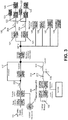
- FIG. 2 is a schematic block diagram of an existing MV DC electrical system incorporating an additional line reactor located at the LV distribution to mitigate harmonic current;
- FIG. 3 is a schematic block diagram of an existing MV DC electrical system incorporating line reactors at the MV and LV distribution points and not incorporating any step-up transformers at the output of an MV uninterruptible power supply (UPS);
- UPS uninterruptible power supply
- FIG. 4 is a circuit diagram of a conventional power distribution unit (PDU) transformer
- FIG. 5 is a circuit diagram of the power distribution unit of FIG. 4 coupled to an external line reactor;
- FIG. 6 is a circuit diagram of a power distribution unit according to embodiments of the present disclosure.
- FIG. 7 is a schematic block diagram of an MV DC electrical system employing a passive filtering configuration according to some embodiments of the present disclosure
- FIGS. 8-10 are schematic block diagrams of MV DC electrical systems employing hybrid active and passive filtering configurations according to other embodiments of the present disclosure.
- FIG. 11 is a schematic block diagram of an MV DC electrical system employing an active filtering configuration according to yet other embodiments of the present disclosure
- FIG. 12 is a schematic block diagram of an exemplary load for a data center according to embodiments of the present disclosure.
- FIG. 13 is a flow diagram of an exemplary method of performing active filtering to generate a harmonic signal to mitigate harmonic current in the electrical system.
- FIG. 14 is a circuit diagram of a DC-DC converter according to embodiments of the present disclosure.
- FIG. 15 is a circuit diagram of a five-level diode-clamped inverter according to embodiments of the present disclosure.
- FIG. 16 is a circuit diagram of an active filter including a two-level inverter according to embodiments of the present disclosure.
- FIG. 1 shows an existing MV DC electrical system for supplying power to server and mechanical cooling loads.
- the system includes a utility/generator power supply system and a MVUPS 130 , a shunt connected Voltage Source Inverter (VSI) with battery energy storage 132 that includes a step-up transformer 136 for MV applications.
- VSI Voltage Source Inverter
- the system also incorporates a line reactor L 115 located at the MV distribution point to mitigate line current harmonics at the grid.
- the line reactor L is coupled to an AC MV line to reduce harmonics in the power supplied by the MV utility supply 111 or generator supply 112 .
- Line reactor L 115 is in the passive filtering mode.
- a step-down transformer 118 is disposed in series with the IT load 120 and the mechanical cooling loads, i.e., a cooling distribution unit (CDU) having a pump 125 , a pump skid having multiple pumps 126 , a fluid cooler having fans 127 , and a chiller having a compressor 128 .
- the IT server load 120 is connected to an AC-DC-DC switching power supply 122 , which, in turn is connected to the PDU transformer 121 .
- An evaporator cooling fan systems 123 are also connected to the PDU transformers 121 .
- the CDU 125 , the pump skid 126 , the fluid cooler 127 , and the chiller 128 are connected to the step-down transformer and are used for mechanical cooling of the IT server load 120 , i.e., to remove waste heat generated by the IT server load 120 .
- the utility supply 111 supplies an AC voltage (ranging from about 3.3 kV to 13.8 kV) for MV application.
- a bypass line 117 allows for maintenance tasks or other work to be performed on the electrical system when an ON/OFF switch (not shown) of the bypass line is closed and a static transfer switch (STS) 116 is opened.
- the STS 116 supplies power to an IT load when it is in the ON position.
- the step-down transformer 118 converts the medium voltage supplied by the utility supply 111 , e.g., 13.8 kV, to a low voltage, e.g., 480 V.
- the PDU transformers 121 are used to generate low voltage (e.g., either 208 V or 230 V) for the IT server load 120 .
- the STS 116 opens and the MVUPS 130 starts supplying about 100% of the power to the load within, for example, 2 to 4 ms via the MVUPS's step-up transformer 136 .
- the MVUPS 130 can supply power to the load for a short period, e.g., approximately two to five minutes depending on Amp-hour storage capacity of the energy storage device 132 , but generally the generator starts producing power if the interruption is more than a few seconds.
- the MVUPS 130 generates power from a low-voltage energy storage device, e.g., one or more lead-acid or lithium-ion batteries arranged in parallel.
- the low voltage of the energy storage device 132 may range, for example, from about 700 V to about 1000 V.
- the voltage of the energy storage device 132 is then converted to a low AC voltage, e.g., 480 V, using a two-level IGBT inverter 134 .
- the AC voltage output from the two-level inverter 134 passes through a filter (not shown), such as an inductor-capacitor (LC) filter, to the step-up transformer 136 .
- a filter not shown
- LC inductor-capacitor
- the step-up transformer 136 converts the low AC voltage (e.g., 480 V) to a medium AC voltage, e.g., 13.8 kV.
- the medium AC voltage output from the step-up transformer 136 is then provided to the step-down transformer 118 , which converts the medium AC voltage, e.g., 13.8 kV, to a low AC voltage, e.g., 480 V, appropriate for the DC loads.
- the transfer switch 114 shifts the primary power source from the utility supply 111 to the generator 112 . During this shift, the output voltage of the MVUPS 130 is synchronized to be in phase with the output voltage of the generator 112 . Once the STS 116 is closed, a soft transfer from the MVUPS 130 to the generator 112 is executed until the load is entirely powered by the generator 112 . The energy storage device 132 of the MVUPS 130 is then recharged by the power generated by the generator 112 .
- the load is shifted from the generator 112 to the MVUPS 130 because the utility supply 111 may be out of phase with the generator 112 and the STS 116 shifts the primary power source to the utility supply 111 .
- the output voltage of the MVUPS 111 is then synchronized to be in phase with the output voltage of the utility supply 111 .
- the load is quickly transferred from the MVUPS 130 to the utility supply 111 .
- the energy storage devices 132 of the MVUPS 111 are recharged from the utility supply 111 so that the MVUPS is ready for future interruptions or disturbances in the utility supply 111 .
- the IT server load 124 is normally powered by the utility supply 111 as shown in FIG. 1 .
- the IT server load 124 draws current harmonics from the utility supply 111 due to the presence of a non-linear power supply to power the IT server load 124 .
- Passive, active, and hybrid filtering techniques are used to reduce current harmonics to adhere to the IEEE-519 and 1547 allowable harmonics standard that may be required by the grid.
- FIG. 2 shows a MV DC electrical system incorporating a line reactor L M 202 located at the MV distribution to mitigate harmonic current.
- Line reactor L M 202 is coupled to AC MV line to reduce harmonics in the power supplied by the utility supply 111 or generator supply 112 .
- the MV DC electrical system also incorporates additional modular line reactors L S located at the LV distribution point at the output of individual existing PDU transformers 121 .
- the combination of line reactors L M and L S reduces a large amount of harmonic current in comparison to FIG. 1 . Both line reactors L M and L S are in the passive filtering mode.
- FIG. 3 shows a multi-level MVUPS electrical system without any step-up transformer and incorporating a line reactor L M 202 located at the MV distribution point.
- the line reactor L M 202 is coupled to AC MV line to reduce harmonics in the power supplied by the utility supply 111 or generator supply 112 .
- SVPWM control of multi-level (ML) inverter 302 in the MVUPS 300 provides advantages of superior harmonic quality in comparison to sinusoidal PWM.
- the ML inverter 302 with LCL filter 310 at its output also provides additional harmonic reduction.
- the LCL filter 310 is used due to use of lower IGBT switching frequency (1 kHz) as it helps to attenuate, for example, 60 dB/decade, above the resonant frequency.
- the multi-level MVUPS 300 reduces harmonics due to use of SVPWM control and the LCL filter 310 at the output of the multi-level MVUPS 300 in comparison to the two-level MVUPS 130 with the step-up transformer 136 . Also, good current ripple attenuation is achieved with small values of inductances in the LCL filter 310 .
- the multi-level MVUPS electrical system also incorporates additional modular line reactors Ls 204 located at the LV distribution side after at the output of the existing PDU transformers 121 . The combination of line reactor L M 202 and line reactors Ls 204 reduce extra harmonic current in comparison to FIG. 1 and provides passive filtering.
- FIG. 4 illustrates a typical configuration of a 3-phase PDU transformer.
- the PDU transformer includes a primary side 410 having windings 411 - 413 in a delta configuration and a secondary side 420 having windings 421 - 423 in a wye configuration with a neutral connection 427 .
- the primary side 410 and the secondary side 420 are electrically isolated from each other 316 .
- FIG. 5 shows both a PDU transformer 500 and a separate line reactor L S module 500 having line reactors 501 - 503 to reduce current harmonics. This configuration is expensive and occupies extra IT space or volume as it contains two discrete magnetic circuits.
- FIG. 6 shows a magnetically coupled PDU transformer 600 with added values of line impedance using leakage inductance coils 601 - 603 in one modular frame.
- the leakage inductance coils 601 - 603 are formed by additional windings coupled to the respective windings 421 - 423 and incorporated into the same package as the windings 421 - 423 .
- FIG. 7 shows a multi-level MVUPS electrical system incorporating the PDU transformer 600 of FIG. 6 according to embodiments of the present disclosure.
- Appropriate values of line impedance may be obtained by adjusting allowable values of leakage inductances of the PDU transformers 600 to reduce line current harmonics.
- the electrical system 700 reduces both size and overall cost. As shown, the electrical system 700 uses a passive filtering configuration.
- FIG. 8 shows an electrical system 800 having a line reactor L M 202 located at the MV supply line.
- the electrical system 800 uses a transformerless medium voltage uninterruptible power supply (MVUPS) 300 including a multi-level inverter 302 and an LCL filter.
- the electrical system 800 also uses LV active filtering (AF) for the IT server assembly 120 coupled to the secondary coils of the PDU transformer.
- MVUPS transformerless medium voltage uninterruptible power supply
- AF LV active filtering
- the electrical system 800 incorporates hybrid filtering including both MV passive and LV active filtering.
- the active filters 802 may include another energy storage device, e.g., the energy storage device 1602 of FIG. 16 , such as an ultracapacitor, a battery, or a combination of the battery and the ultracapacitor, a two-level inverter, e.g., the two-level inverter 1606 of FIG. 16 , and LCL filters, e.g., the LCL filters 1608 of FIG. 16 , to provide harmonic current to compensate for the harmonic current drawn by the nonlinear electrical components of the IT server assembly 120 and the mechanical cooling equipment 125 - 128 .
- another energy storage device e.g., the energy storage device 1602 of FIG. 16
- the energy storage device 1602 of FIG. 16 such as an ultracapacitor, a battery, or a combination of the battery and the ultracapacitor
- a two-level inverter e.g., the two-level inverter 1606 of FIG. 16
- LCL filters e.g., the LCL filters 16
- the other energy storage device of the active filter 802 is coupled in parallel with the two-level inverter, and the two-level inverter is coupled in series with the LCL filters.
- the two-level inverter is controlled by a digital signal processor.
- FIG. 9 shows an electrical system 900 incorporating a transformerless MV DCSTATCOM.
- the electrical system includes the DC-DC converter 133 , the multi-level inverter 302 , LCL filter 310 , and a controller 935 coupled to the DC-DC converter 133 and the multi-level inverter 302 located at the medium voltage utility/grid side 910 .
- the controller 935 generates space vector pulse width modulation (SVPWM) signals and operates the multi-level inverter 302 using the SVPWM signals.
- the controller 935 also operates the DC-DC converter 133 and the multi-level inverter 302 in Active Filtering and MVUPS operation modes. In embodiments, the MVUPS mode is enabled during an interruption in power.
- SVPWM space vector pulse width modulation
- the electrical system also includes, at the load side 920 , existing PDU transformers 121 and line reactors 204 coupled to the secondary side of the PDU transformers 121 .
- the electrical system 900 incorporates hybrid filtering including MV active filtering and LV passive filtering.
- the control circuits for active filtering analyze and determine the harmonic components of the current with respect to the fundamental component of the current (e.g., all or a portion of the harmonic components within the range of the second harmonic component to the thirty-fifth harmonic component) delivered to the load and inject opposite harmonic currents to mitigate the overall line harmonics current.
- a current sensor 825 of the electrical systems of FIGS. 8 and 11 senses a current at a location between the active filters 802 and the IT server assemblies 120 and/or a current sensor 925 of the electrical systems of FIGS.
- the 9-11 senses a current at a location between the PCC and the transfer switch 114 , and the current is filtered by a high-pass filter to obtain the harmonic components of the current with respect to the fundamental component of the current.
- the active filtering can achieve minimum current harmonic distortion levels.
- the cost to implement active filtering is high because of the use of power electronics devices, e.g., the multi-level inverter 302 , and the DSP devices, e.g., the controller 935 , used to control the power electronics devices.
- the electrical system may be designed to obtain a minimum or a reasonable amount of harmonic current reductions for any particular application so that the implementation costs are minimized or are at a reasonable level.
- the cost of the AF to reduce the overall current harmonics to 15% is less than the cost of the AF to reduce the overall current harmonics to 5% as the AF to reduce the overall current harmonics to 15% needs to inject less harmonic current into the electrical system to cancel harmonic current at that level.
- the active (P) power compensation portion supplies the harmonic current by operating the switching devices, e.g., IGBTs, of the multi-level inverter 302 to compensate for the harmonic component of the current from the nonlinear load.
- the reactive (Q) power compensation portion maintains the power factor at PCC.
- the phase angle ⁇ is controlled to be a positive value to supply harmonic current in the case of AF mode and/or fundamental current in the case of MVUPS during an interruption in power from the MV utility supply 111 .
- the phase angle determines harmonic current to compensate for the line harmonics introduced by the nonlinear load from the switching of the power supplies.
- FIG. 10 shows another electrical system 1000 that is the same as the electrical system 900 of FIG. 9 , except that each combination of the existing PDU transformer 121 and the line reactor 204 is replaced by the PDU transformer 600 of FIG. 6 on the load side 920 .
- the electrical system 1000 incorporates hybrid filtering including MV active filtering and LV passive filtering.
- FIG. 11 shows still another electrical system 1100 that is the same as the electrical system 900 of FIG. 9 , except that each line reactor 204 is replaced by the active filter 802 in parallel with the existing PDU transformer 121 .
- the electrical system 1100 incorporates active filtering including both MV active filtering and LV active filtering.
- FIG. 12 shows the load side of the electrical systems of the present disclosure.
- the load side includes the server racks, the evaporative cooling devices, the CDUs, the pump skids, the fluid coolers, and the chillers.
- the server racks each include an AC-DC-DC power supply 122 , rack 1202 to hold the power supply and the server, and the IT server load 124 .
- the evaporative cooling devices each include a fan drive 1204 and a fan 123 electrically coupled to the fan drive 1204 .
- the AC-DC-DC power supplies 122 and the fan drives 1204 are electrically coupled to the step-down transformer 118 via the PDU transformer 121 .
- the CDUs each include a variable frequency drive 1206 and a pump motor 1208 electrically coupled to the variable frequency drive 1206 .
- the pump skid includes variable frequency drives 1206 and pump motors 1210 electrically coupled to respective variable frequency drives 1206 .
- the fluid coolers include fan drives 1204 and fans 1212 electrically coupled to respective fan drives 1204 .
- the chillers include variable frequency drives 1206 and compressors 1210 electrically coupled to respective variable frequency drives 1206 .
- the variable frequency drives 1206 of the CDUs, the pump skid, and the chillers, and the fan drives 1204 of the fluid coolers are electrically coupled to the step-down transformer 118 .
- Table 1 shows exemplary specifications of a 1 MW data center module that includes 100 IT server rack modules (with the assumption that average IT capacity of each rack is 10 kW).
- the IT servers need a 3-phase AC supply having 3084 fundamental amperes and 208 volts.
- the remaining equipment e.g., the evaporator cooling device, the CDUs, the pump skid, the fluid cooler, and the chiller are used to cool the IT server racks.
- the average cooling capacity of each evaporator cooling device is 30 kW. Therefore, 34 evaporator cooling devices are needed to provide 1 MW cooling capacity.
- the evaporator cooling devices need a 1-phase AC supply having 174 A (with respect to 3-phase) and 208 V.
- the average cooling capacity of each CDU is 335 kW. Therefore, 3 CDUs are needed to provide 1 MW cooling capacity.
- the CDUs need a 3-phase AC supply having 30 A and 480 V.
- the average cooling capacity of the pump skid is 1 MW. Therefore, one pump skid is needed to provide 1 MW cooling capacity.
- the pump skid needs 3-phase AC supply having 30 A and 480 V.
- the average cooling capacity of each fluid cooler is 500 kW. Therefore, 2 fluid coolers are needed to provide 1 MW cooling capacity.
- the fluid coolers need a 3-phase AC supply having 50 A and 480 V.
- the average cooling capacity of each chiller module is 500 kW. Therefore, 2 chiller modules are needed to provide 1 MW cooling capacity.
- the chiller modules need 3-phase AC supply having 320 A at 480 V. Therefore, 378 kW of additional power is needed for all the mechanical cooling equipment to cool 1 MW IT load at extreme ambient conditions.
- Table 2 shows that a total of 1842 amps of 3-phase fundamental current are needed for a 1 MW DC block at 480 V.
- the existing electrical system of FIG. 1 with a 5% line reactor L at MV generates a total of 645 amps of harmonic current.
- the maximum achievable current distortion level is 35%. Therefore, the total harmonic distortion current (THD-I) at the grid is 35%.
- the THD-I for IT server racks is also 35%. According to the IEEE 519 standard, the maximum allowed THD-I limit is 8%.
- the total harmonic distortion is the amount of distortion, i.e., the second and greater harmonics, in the current or voltage waveform with respect to the fundamental, i.e., the first harmonic, current or voltage waveform.
- the hybrid filtering technique is implemented to further improve the THD-I.
- both passive and active filtering are performed.
- the hybrid filtering technique implemented in FIG. 8 also provides active filtering having a 15% compensation capacity for IT servers and evaporative cooling devices.
- the total harmonic distortion current (THD-I) at the grid is 8%, which satisfies the IEEE 519 standard and is lower than the THD-I of the electrical systems of FIGS. 2, 3, and 6 .
- the THD-I for the IT server racks is 5%.
- both the active and passive filtering are performed.
- the hybrid filtering techniques implemented in the electrical systems of FIGS. 9 and 10 also provide 5% compensation from the line reactor L S at the LV side for the IT servers and evaporative cooling devices.
- the hybrid filtering techniques implemented in the electrical systems of FIGS. 9 and 10 generates 102 amps of harmonic current.
- the total harmonic distortion current (THD-I) at the grid is 6%, which is lower than the maximum limit specified by the IEEE 519 standard and is lower than the THD-I of FIG. 8 .
- the THD-I for the IT server racks is 5%.
- Table 3 illustrates the THD-I values for various filtering configurations and the relative cost to implement those filtering configurations to mitigate harmonic line current.
- the existing passive filtering of FIG. 1 is low cost because a single line inductor L is used.
- the overall THD-I is 35% at the grid. This is higher than the allowed 8% current harmonics specified by the IEEE 519 standard.
- the efficiency of the electrical system is low because of the presence of extra higher harmonic current, e.g., 645 amps, in the electrical system.
- the cost of the existing passive filtering employed in the electrical system of FIG. 1 is 15% with respect to the cost of the MV and LV active filtering technique employed in FIG. 11 .
- the passive filtering techniques employed in the electrical systems of FIGS. 2, 3 and 6 are more expensive than the passive filter technique employed in FIG. 1 because of the use of two line inductors L M and L S in the electrical systems of FIGS. 2 and 3 and the use of the line inductor L M and coupled to the PDU of FIG. 6 .
- the overall THD-I is 13% at the grid. This is higher than the 8% current harmonics allowed by the IEEE 519 standard.
- the passive filtering technique employed in the electrical systems of FIGS. 2, 3, and 6 also increases efficiency of the electrical system because of the lower current harmonics, e.g., 237 amps, in the electrical system, which is lower than the current harmonics of FIG. 1 .
- FIGS. 2 and 3 with independent discrete magnetic circuits
- the total 10% line voltage drop occurs across both of the line inductors.
- the cost of the passive filtering technique employed in the electrical systems of FIGS. 2, 3 , and 6 is 30% of the cost of the active filtering technique employed in FIG. 11 .
- the first hybrid filtering technique employed in the electrical system of FIG. 8 is more expensive than the passive filtering techniques employed in the electrical systems of FIGS. 2, 3, and 6 because of the use of MV passive filtering using the line reactor L M and LV active filtering.
- the overall THD-I is 8% at grid and thus satisfies the IEEE 519 standard.
- the efficiency of the electrical system employing the first hybrid filtering technique is higher because of the lower harmonics current, e.g., 138 amps).
- the cost of the first hybrid filtering configuration employed in the electrical system 800 of FIG. 8 may be 55% of the cost of the MV and LV active filtering configuration employed in the electrical system of FIG. 11 .
- the electrical systems employing the second hybrid filtering configuration of FIGS. 9 and 10 are more expensive than the electrical system employing the second hybrid filtering techniques of FIG. 8 because of the use of both MV active filtering and LV passive filtering.
- the overall THD-I is 6% at the grid, which is lower than the IEEE 519 standard.
- the efficiency of the electrical systems of FIGS. 9 and 10 are better because of the lower harmonic current, e.g., 102 amps.
- the cost of the second hybrid filing configuration employed in the electrical systems of FIGS. 9 and 10 may be 75% of the cost of the MV and LV active filtering configuration of FIG. 11 .
- the relative cost of using the MV and LV active filtering configuration to mitigate harmonics as illustrated by FIG. 11 is the greatest in comparison to the passive and hybrid filtering configurations.
- the overall THD-I at the grid is 4% and the efficiency of the electrical system of FIG. 11 is the best compared to the efficiency of the hybrid and fully passive configurations because the current harmonics are at minimum, e.g., 79 amps in the exemplary specifications of Table 2.
- the MV and LV active filtering configuration also increases the equipment life cycle, reduces occasional malfunctions of the DSP controllers, reduces safety hazards associated with higher current, and possibly reduces or eliminates the potential penalties imposed by the utility. Also, there is no line voltage drop across the active filters.
- the first and second hybrid configurations fulfill the harmonic requirement of the IEEE 519 standard, i.e., 8% limit at the grid, with lower cost in comparison to the full active filtering configuration. In some applications, however, the cost may not be a factor, but the overall performance and efficiency of the electrical system may be a factor. Thus, the selection of the filtering technique for a particular application depends upon a number of factors including the cost, the harmonic requirements, and the efficiency requirements.
- FIG. 13 is a flow diagram of an example process performed by the controller 935 and the controller of FIG. 8 to compensate for the grid harmonic current.
- a first DC voltage is supplied from an energy storage device, e.g., energy storage device 132 or energy storage device 1602 , in step 1302 .
- the first DC voltage is converted into a second DC voltage.
- Step 1304 may not be performed in the active filters 802 that do not include a DC-DC converter 1604 because the voltage of the energy storage device 1602 is high enough to not require the DC-DC converter 1604 , which acts as a boost converter.
- an AC voltage is generated from the second DC voltage or, in the case where the DC-DC converter 1604 is not included in the active filter 802 , the AC voltage is generated from the first DC voltage.
- a load current is measured, for example, by the current sensor 825 and/or the current sensor 925 .
- the measured load current is filtered using a high pass filter to obtain a harmonic portion of the measured load current, e.g., the controller 835 and/or the controller 935 filters the measured load current.
- an opposite harmonic current is generated based on the harmonic portion of the measured load current.
- the opposite harmonic current is an AC current that is 180 degrees out of phase from the harmonic portion of the measured load current.
- the opposite harmonic current is supplied to the grid.
- the opposite harmonic current is supplied to the grid at the point of common coupling (PCC).
- FIG. 14 depicts a DC-DC converter 1400 , which may be employed as the DC-DC converter 133 of FIGS. 7-11 and which may be employed in the active filter 802 of FIGS. 8 and 11 .
- the DC-DC converter 1400 is a bi-directional two-stage DC-DC converter having a first stage 1424 and a second stage 1426 .
- the first DC-DC stage 1424 converts the voltage from the energy storage device 132 into voltage V 1 .
- Voltage V 1 is a DC voltage higher than the voltage of the energy storage device 132 .
- the second DC-DC stage 1426 converts the voltage V 1 into voltage V 2 , which is higher than voltage V 1 .
- the voltage boost from the first and second stages 1424 , 1426 can range from about 1:5 to about 1:10.
- the voltage boost of the DC-DC converter 1400 can be adjusted by changing the size of the switches at each level, the number of stages, and/or the number of levels in each stage.
- the optimum boost voltage requirement is based on the given voltage of the energy storage device 132 and the required voltage output from the inverter 302 .
- the boost voltage ratio can be lower.
- the boost voltage ratio can be higher.
- the efficiency of the DC-DC converter 1400 is reduced when the boost ratio is greater than about 7.
- output capacitor C 0 and inductor L 0 connect the first stage 1424 to the second stage 1426 .
- the first stage 1424 of the DC-DC converter 1400 is shown as a bidirectional, two-level DC-DC converter having one insulated gate bipolar transistor (IGBT) switch S U connected in series with another IGBT switch S L .
- the switches S U and S L are connected to the energy storage device 132 of FIGS. 7-11 , for example, through an LC filter, which includes capacitor C and inductor L.
- the first stage 1424 may provide a range of duty or boost ratios.
- the boost ratio may range from 0 to 0.9.
- the output voltage (V 1 ) ranges from 1 kV to 10 kV depending on the value of the boost ratio, as shown in Table 4.
- the voltage V 1 varies depending upon the inductance of L multiplied by the rate of change of current di/dt.
- voltage V 1 refers to the voltage output of the first stage 1424 of the DC-DC converter 1400 .
- voltage V 2 refers to the output voltage of the second stage 1426 of the DC-DC converter 1400 .
- the IGBT in switch S U may be configured in such a way as to handle a lower voltage and a higher current. Furthermore, because the IGBT of switch S U is handling a lower voltage, the overall size of the IGBT may be smaller.
- the two-stage bidirectional DC-DC converter 1400 is a bi-directional converter.
- Switches S U and S 1dc -S 4dc are used to discharge the energy storage 132 ) and switches S L and S 5 -S 8 are used to charge the energy storage device 132 .
- switch S U is configured as a boost converter that converts the voltage Vs of the energy storage device 132 to a higher voltage
- switch S L is configured as a buck converter that converts voltage from the utility supply 111 to a lower voltage appropriate for charging the energy storage device 132 , e.g., a voltage slightly more than Vs.
- Each of the switches S 1dc -S 8dc outputs a voltage equal to the input voltage V 1 . Since the switches S 1dc -S 8dc are connected in series, the output voltage V 2 is equal to the sum of the voltages output from each of the switches S 1dc -S 8dc . Thus, the boost ratio is 4:1 and V 2 equals 4 ⁇ V 1 .
- the capacitors C 1 -C 4-4 are relatively small capacitors, e.g., capacitors rated for about 5 kV with a capacitance value that is about ten times less than a capacitor for a conventional DC-DC converter. For example, if a conventional two-level DC-DC converter needs a capacitor having a value of about 2000 ⁇ F, then the multi-level flying capacitor arrangement (e.g., C 1 -C 4-4 ) needs a capacitor having a value of about 200 ⁇ F.
- each switch S 1dc -S 4dc operates at a fixed duty cycle of 25% and a fixed switching frequency without pulse width modulation.
- the voltages across the capacitors C 1 -C 4-4 may be balanced in every switching cycle due to fixed duty cycle operation. Additionally, the voltage across each switch S 1dc -S 4dc maintains 25% of the high voltage V 2 .
- the number of capacitors coupled in series between the collectors of switches arranged in the upper portion of a stage and the emitters of the switches arranged in the lower portion of the stage depends on the level of the switch to which the capacitors are coupled.
- the DC-DC converter 1400 may include any number of capacitors coupled in series between the collectors and emitters of appropriate switches to achieve a desired result.
- the DC-DC converter 1400 of FIG. 14 is a five-level converter in a flying capacitor configuration.
- FIG. 15 shows a five-level diode-clamped inverter 1500 , which may be employed as the multi-level inverter 302 of FIGS. 7-11 and which may be used to convert the DC voltage output V 2 from the DC-DC converter 1400 to three-phase AC voltage V 3 .
- the five-level inverter 1500 includes three groupings of switches and diodes 1502 , 1504 , and 1506 to generate the three phases of the AC voltage V 3 , which is the output voltage of the inverter 1500 .
- Each grouping of diodes and corresponding switches S 1U -S 8U , S 1V -S 8V , and S 1W -S 8W are connected together in a diode-clamped configuration.
- Switches S 1U -S 8U , S 1V -S 8V , and S 1W -S 8W may be IGBTs. IGBTs allow for higher voltages/currents and higher switching frequencies.
- the five-level inverter 1500 illustrated in FIG. 15 allows for sharing of the high voltage among the switches S 1U -S 8U , S 1V -S 8V , and S 1W -S 8W , and reduces harmonic distortion.
- the switches S 1U -S 8U , S 1V -S 8V , and S 1W -S 8W are controlled by controller 935 , which may include a digital signal processor (DSP).
- the DSP may use a space vector pulse width modulation (SVPWM) technique for operating the switches S 1U -S 8U , S 1V -S 8V , and S 1W -S 8W in such a way that the neutral-point voltage remains balanced in open-loop operation.
- the SVPWM technique is an inverter modulation technique for synthesizing a voltage space vector V* over a modulation sampling period T S .
- SVPWM control methods that can be used to control the multi-level inverters is described in PCT Patent Application No. PCT/US15/56785 (which published on Apr. 28, 2016, with Publication No. WO 2016/065087), the entire contents of which are incorporated herein by reference.
- the SVPWM technique provides the advantages of superior harmonic quality and large under-modulation range that extends the modulation factor from 78.5% to 90.7%.
- an artificial neural network (ANN) control technique can be used to reduce harmonics outputted from the inverter 1500 .
- FIG. 16 is an embodiment of an active filter 1600 , which may be employed as the active filter 802 of FIGS. 8 and 11 .
- the active filter 1600 includes an energy storage device 1602 , a two-level inverter 1606 , and LCL filters 1608 coupled to respective outputs of the two-level inverter 1606 .
- the active filter 1600 optionally includes a DC-DC converter 1604 .
- the DC-DC converter 1604 may be needed in active filters 802 that include a very low voltage energy storage device 1602 so that the voltage can be boosted prior to the two-level inverter 1606 .
- the energy storage device 1602 may be a battery, an ultracapacitor, or a combination of a battery and an ultracapacitor.
- the DC-DC converter 1604 is a two-level DC-DC converter having switch S U and switch S L connected together in series.
- the switches S U and S L may be insulated gate bipolar transistors (IGBTs).
- the switches S U and S L are connected to the energy storage device 132 through an LC filter.
- the two-level inverter 1606 includes three pairs of series-connected switches, e.g., IGBTs, which are coupled together in parallel.
- the two-level inverter 1606 may be controlled according to space vector pulse width modulation (SVPWM) control to increase the linear operating range of the two-level inverter (e.g., from 78.5% to 90.7%) and to reduce the harmonic levels at the output of the two-level inverter 1606 as compared to sinusoidal PWM-based (SPWM) control.
- SVPWM space vector pulse width modulation
- the switches of the DC-DC converter 1604 and the two-level inverter 1606 are controlled by a controller (not shown), which may include a digital logic circuit, such as a Field Programmable Gate Array (FPGA), and/or a processor, such as a digital signal processor (DSP) or a microprocessor.
- a controller may include a digital logic circuit, such as a Field Programmable Gate Array (FPGA), and/or a processor, such as a digital signal processor (DSP) or a microprocessor.
Landscapes
- Engineering & Computer Science (AREA)
- Power Engineering (AREA)
- Inverter Devices (AREA)
- Business, Economics & Management (AREA)
- Emergency Management (AREA)
Abstract
Description
P=3*V GRID *V INV*sin δ/ω*L (1)
Q=3*V GRID*(V INV*cos δ−V GRID)/ω*L (2)
where ω is the line frequency and L is the effective line reactance of the LCL filters. The active (P) power compensation portion supplies the harmonic current by operating the switching devices, e.g., IGBTs, of the
| TABLE 1 |
| 1 MW Data Center Module |
| Amps | ||||||
| Equipment | Quantity | Harmonic Sources | kW | (3-Phase) | Individual Capacity | Comments |
| IT server racks: | 100 | AC-DC- |
1000 | 3084 | Server Rack: | 1000 kW; |
| 208 V, 3-phase | Power supplies for Server | 10 kW (average) | Power for IT | |||
| (120 V, 1-phase) | board, CPU, Memory, | (100 × 10 = 1 MW IT | server Load | |||
| hard drives etc. | electrical load) | |||||
| |
34 | Non-linear EC Fan Drive | 57 | 174 | Heat absorption: 30 kW | 378 kW; |
| cooling devices: | for EC fans, Switching | (each includes 4 EC Fans | Power for |
|||
| 208 V LL, 1-phase | Power supplies for | totaling 136 fans) | server | |||
| Control etc. | (34 × 30 = 1 MW cooling | cooling | ||||
| capacity) | equipment | |||||
| CDUs: | 3 | Non-linear VFD Drive for | 22 | 30 | Heat absorption: 335 | (worst |
| 480 V, 3-phase | Pump Motor, Switching | kW each (each includes | ambient | |||
| Power supplies for | one Pump) (3 × 335 = | condition) | ||||
| Control etc. | 1 MW cooling capacity) | |||||
| Pump skid: | 1 | Each Pump house has | 22 | 30 | Heat absorption: | |
| 480 V, 3-phase | two Pump motors; Non- | 1 MW capacity | ||||
| linear VFD Drive for Pump | ||||||
| Motor, Switching Power | ||||||
| supplies for Control etc. | ||||||
| Fluid coolers: | 2 | Non-linear EC Fan Drive | 37 | 50 | Heat absorption: 500 |
|
| 480 V, 3-phase | for EC fans, Switching | (each includes 8 EC | ||||
| Power supplies for | Fans totaling 16 fans) | |||||
| Control etc. | (2 × 500 = 1 MW cooling | |||||
| capacity) | ||||||
| Chiller module: | 2 | Non-linear VFD Drive for | 239 | 320 | Heat absorption: 500 |
|
| 480 V, 3-phase | Compressor Motor, | (each includes one | ||||
| Switching Power supplies | Compressor) (2 × 500 = | |||||
| for Control etc. | 1 MW cooling capacity) | |||||
| TABLE 2 |
| Individual and Total Current Harmonics |
| Passive | Hybrid | |||||||||||
| Filter | Hybrid | Filter: 2 | Active | |||||||||
| Existing | Indi- | (FIGS. 2, | Indi- | Filter:1 | Indi- | (FIGS. 9, | Indi- | Filter | Indi- | |||
| Amps | (FIG. 1) | vidual | 3, 6) | vidual | (FIG. 8) | vidual | 10) | vidual | (FIG. 11) | vidual | ||
| Data Center | Amps | (3-Phase) | harmonics | THD- | harmonics | THD- | harmonics | THD- | Harmonics | THD- | Harmonics | THD- |
| Loads | (3-Phase) | at 480 V | Amps | I % | Amps | I % | Amps | I % | Amps | I % | Amps | I % |
| IT racks | 3084 | 1336 | 468 | 35 | 164 | 12 | 70 | 5 | 70 | 5 | 40 | 3 |
| Evaporator | 174 | 76 | 26 | 35 | 9 | 12 | 4 | 5 | 4 | 5 | 2 | 3 |
| cooling devices | ||||||||||||
| CDUs | 30 | 30 | 11 | 35 | 4 | 12 | 4 | 12 | 2 | 5 | 2 | 7 |
| Pump Skid | 30 | 30 | 10 | 35 | 4 | 12 | 4 | 12 | 2 | 5 | 2 | 7 |
| Fluid Cooler | 50 | 50 | 18 | 35 | 18 | 35 | 18 | 35 | 8 | 15 | 10 | 20 |
| Chiller | 320 | 320 | 112 | 35 | 39 | 12 | 39 | 12 | 17 | 5 | 22 | 7 |
| Total | 1842 | |||||||||||
| Fundamental | ||||||||||||
| Amps | ||||||||||||
| Total Harmonics | 645 | 237 | 138 | 102 | 79 | |||||||
| (Amps) | ||||||||||||
| % THD-I at Grid | 35 | 13 | 8 | 6 | 4 | |||||||
| Comments | L at MV | LM, | LM, | 15% AF | 20% AF | |||||||
| Grid | effective | 15% AF | at MV, | at MV, | ||||||||
| LS and | at LV and | effective | 15% AF at | |||||||||
| additional | additional | LS and | LV and | |||||||||
| line | line | additional | additional | |||||||||
| reactors | reactors | line reactors | line reactors | |||||||||
| for other | for other | for other | for other | |||||||||
| loads | loads | loads | loads | |||||||||
THD-I=I Total Harmonic /I 1 (3)
where ITotal Harmonic is the total harmonic current and I1 is the fundamental current, i.e., the first harmonic current.
| TABLE 3 |
| Current THD (THD-I) value and relative cost of various filtering configurations |
| IT and | Pump | Fluid | |||||||
| Filtering | Grid side | eSYNC | CDU | Skid | Cooler | Chiller | Relative | ||
| Technique | THD-I | THD-I | THD-I | THD-I | THD-I | THD-I | Comments | Comments | Cost |
| Existing | 35% due to L for | 35% due | 35% due | 35% due | 35% | 35% due | Regular PDU | Line filter L: | 15% |
| Passive | non-linear DC | to L | to L | to L | due to | to L | Transformer | 5% line | |
| Filtering | load | L | impedance | ||||||
| (FIG. 1) | |||||||||
| Passive | 13% due to LM, | 12% due | 12% due | 12% due | 35% | 12% due | Either due to | Line filters LM | 30% |
| Filtering | effective LS and | to both LM | to both LM | to both LM | due to | to both | external LS or | and LS: 5% line | |
| (FIGS. 2, | Line filters for | and LS | and 5% | and 5% | LM | LM and | coupled PDU | impedance | |
| 3, and 6) | non-linear DC | VFD line | VFD line | 5% VFD | Transformer | ||||
| load | Filter | Filter | line Filter | ||||||
| Hybrid | 8% due to LM, | 5% due to | 12% due | 12% due | 35% | 12% due | Regular PDU | Line filter LM: 5% | 55% |
| Filtering 1 | LV AF and Line | both LM | to both LM | to both LM | due to | to both | Transformer | line impedance; | |
| (FIG. 8) | filters for non- | and LV | and 5% | and 5% | LM | LM and | 15% THD-I | ||
| linear DC load | AF (15% | VFD line | VFD line | 5% VFD | reduction by LV | ||||
| capacity) | Filter | Filter | line Filter | AF (to optimize | |||||
| AF cost) | |||||||||
| Hybrid | 6% due to | 5% due to | 5% due to | 5% due to | 15% | 5% due to | Either due to | 15% THD-I | 75% |
| Filtering 2 | DCSTATCOM | both MV | both MV | both MV | due to | both MV | external LS or | reduction by MV | |
| (FIGS. 9 | MV AF, effective | AF and LS | AF and | AF and | MV | AF and | coupled PDU | AF (to optimize | |
| and 10) | LS and Line filters | 5% VFD | 5% VFD | AF | 5% VFD | Transformer | AF cost); Line | ||
| for non-linear DC | line Filter | line Filter | line Filter | filter LS: 5% line | |||||
| load | impedance | ||||||||
| Active | 4% due to | 3% due to | 7% due to | 7% due to | 20% | 7% due to | No LM or LS | 20% THD-I | 100% |
| Filtering | DCSTATCOM | both MV | both MV | both MV | due to | both MV | are needed; | reduction by MV | |
| (FIG. 11) | MV AF and LV | AF and LV | AF and | AF and | MV | AF and | Regular PDU | AF (to optimize | |
| AF for non-linear | AF | 5% VFD | 5% VFD | AF | 5% VFD | Transformer | MV AF cost | ||
| DC load | line Filter | line Filter | line Filter | further) and 15% | |||||
| LV AF | |||||||||
| TABLE 4 | |||
| VS (~1 kV) | Duty (Boost) | V1 | |
| 1 kV | 0 | 1 |
| 1 kV | 0.2 | 1.25 kV |
| 1 kV | 0.4 | 1.66 kV |
| 1 kV | 0.6 | 2.5 kV |
| 1 kV | 0.7 | 3.3 kV |
| 1 kV | 0.8 | 5 |
| 1 kV | 0.9 | 10 kV |
Claims (20)
Priority Applications (2)
| Application Number | Priority Date | Filing Date | Title |
|---|---|---|---|
| US15/333,177 US10931190B2 (en) | 2015-10-22 | 2016-10-24 | Systems and methods for mitigating harmonics in electrical systems by using active and passive filtering techniques |
| US17/182,035 US20220014088A1 (en) | 2015-10-22 | 2021-02-22 | Systems and methods for mitigating harmonics in electrical systems by using active and passive filtering techniques |
Applications Claiming Priority (2)
| Application Number | Priority Date | Filing Date | Title |
|---|---|---|---|
| US201562244862P | 2015-10-22 | 2015-10-22 | |
| US15/333,177 US10931190B2 (en) | 2015-10-22 | 2016-10-24 | Systems and methods for mitigating harmonics in electrical systems by using active and passive filtering techniques |
Related Child Applications (1)
| Application Number | Title | Priority Date | Filing Date |
|---|---|---|---|
| US17/182,035 Continuation US20220014088A1 (en) | 2015-10-22 | 2021-02-22 | Systems and methods for mitigating harmonics in electrical systems by using active and passive filtering techniques |
Publications (2)
| Publication Number | Publication Date |
|---|---|
| US20170117748A1 US20170117748A1 (en) | 2017-04-27 |
| US10931190B2 true US10931190B2 (en) | 2021-02-23 |
Family
ID=58559402
Family Applications (2)
| Application Number | Title | Priority Date | Filing Date |
|---|---|---|---|
| US15/333,177 Active 2037-12-14 US10931190B2 (en) | 2015-10-22 | 2016-10-24 | Systems and methods for mitigating harmonics in electrical systems by using active and passive filtering techniques |
| US17/182,035 Pending US20220014088A1 (en) | 2015-10-22 | 2021-02-22 | Systems and methods for mitigating harmonics in electrical systems by using active and passive filtering techniques |
Family Applications After (1)
| Application Number | Title | Priority Date | Filing Date |
|---|---|---|---|
| US17/182,035 Pending US20220014088A1 (en) | 2015-10-22 | 2021-02-22 | Systems and methods for mitigating harmonics in electrical systems by using active and passive filtering techniques |
Country Status (1)
| Country | Link |
|---|---|
| US (2) | US10931190B2 (en) |
Cited By (3)
| Publication number | Priority date | Publication date | Assignee | Title |
|---|---|---|---|---|
| EP4145673A1 (en) * | 2021-09-06 | 2023-03-08 | Huawei Digital Power Technologies Co., Ltd. | Power supply system |
| US20230108992A1 (en) * | 2012-07-09 | 2023-04-06 | Inertech Ip Llc | Transformerless multi-level medium-voltage uninterruptable power supply (ups) systems and methods |
| US20240195175A1 (en) * | 2022-12-09 | 2024-06-13 | Adaptr, Inc. | Grid adapter systems and methods |
Families Citing this family (14)
| Publication number | Priority date | Publication date | Assignee | Title |
|---|---|---|---|---|
| US9318974B2 (en) * | 2014-03-26 | 2016-04-19 | Solaredge Technologies Ltd. | Multi-level inverter with flying capacitor topology |
| EP2978122A1 (en) * | 2014-07-22 | 2016-01-27 | ABB Technology AG | Model predictive control of a modular multilevel converter |
| US10170911B1 (en) * | 2016-08-25 | 2019-01-01 | Veritone Alpha, Inc. | Providing phase synchronization and harmonic harvesting |
| DE102017211351A1 (en) * | 2017-07-04 | 2019-01-10 | Siemens Aktiengesellschaft | Uninterruptible power supply |
| DE102017211354A1 (en) * | 2017-07-04 | 2019-01-10 | Siemens Aktiengesellschaft | Uninterruptible power supply |
| CN111108673B (en) * | 2017-09-28 | 2024-02-09 | 开利公司 | pulse width modulation interleaving |
| CN108521144A (en) * | 2018-04-24 | 2018-09-11 | 北京铂阳顶荣光伏科技有限公司 | Photovoltaic generating system and harmonic suppressing method and equipment |
| WO2020219088A1 (en) * | 2019-04-26 | 2020-10-29 | Siemens Energy, Inc. | System for hydraulic fracturing integrated with electrical energy storage and black start capability |
| CN115769459A (en) * | 2020-07-13 | 2023-03-07 | Abb瑞士股份有限公司 | ups |
| FR3115640B1 (en) * | 2020-10-26 | 2023-11-24 | Vitesco Technologies | Device for controlling an on-board electric charger DC-DC converter |
| US11211816B1 (en) | 2020-11-20 | 2021-12-28 | Abb Schweiz Ag | Delta connected resonant turn off circuits |
| US11258296B1 (en) | 2020-11-20 | 2022-02-22 | Abb Schweiz Ag | Shared resonant turn off circuit |
| WO2022203658A1 (en) * | 2021-03-23 | 2022-09-29 | Mohammed Alobaidi | Dc-dc battery adapter for fast charging of electric vehicles |
| CN114731057A (en) * | 2022-02-15 | 2022-07-08 | 烟台杰瑞石油装备技术有限公司 | Electrically driven pumping system and driving method thereof |
Citations (129)
| Publication number | Priority date | Publication date | Assignee | Title |
|---|---|---|---|---|
| US5200644A (en) | 1988-05-31 | 1993-04-06 | Kabushiki Kaisha Toshiba | Air conditioning system having battery for increasing efficiency |
| US5343080A (en) * | 1991-11-15 | 1994-08-30 | Power Distribution, Inc. | Harmonic cancellation system |
| US5343079A (en) | 1991-02-25 | 1994-08-30 | Regents Of The University Of Minnesota | Standby power supply with load-current harmonics neutralizer |
| US5612580A (en) | 1995-10-10 | 1997-03-18 | Northrop Grumman Corporation | Uninterruptible power system |
| US5694312A (en) | 1992-06-10 | 1997-12-02 | Digital Equipment Corporation | Uninterruptible power supply with fault tolerance in a high voltage environment |
| US5715693A (en) | 1996-07-19 | 1998-02-10 | Sunpower, Inc. | Refrigeration circuit having series evaporators and modulatable compressor |
| US5818379A (en) | 1996-03-19 | 1998-10-06 | Samsung Electronics, Co., Ltd. | Flash analog to digital (A/D) converter with reduced number of comparators |
| US6116048A (en) | 1997-02-18 | 2000-09-12 | Hebert; Thomas H. | Dual evaporator for indoor units and method therefor |
| US6160722A (en) | 1999-08-13 | 2000-12-12 | Powerware Corporation | Uninterruptible power supplies with dual-sourcing capability and methods of operation thereof |
| US6201720B1 (en) | 2000-02-18 | 2001-03-13 | Powerware Corporation | Apparatus and methods for space-vector domain control in uninterruptible power supplies |
| US6374627B1 (en) | 2001-01-09 | 2002-04-23 | Donald J. Schumacher | Data center cooling system |
| US6404655B1 (en) | 1999-12-07 | 2002-06-11 | Semikron, Inc. | Transformerless 3 phase power inverter |
| US20020172007A1 (en) | 2001-05-16 | 2002-11-21 | Pautsch Gregory W. | Spray evaporative cooling system and method |
| US20030052543A1 (en) | 2001-09-18 | 2003-03-20 | C & D Charter Holdings, Inc. | Modular power distribution system |
| US20030061824A1 (en) | 2000-04-04 | 2003-04-03 | Joseph Marsala | Pumped liquid cooling system using a phase change refrigerant |
| US20030076696A1 (en) | 2001-10-18 | 2003-04-24 | Delta Electronics, Inc. | Device of uninterruptible power supply |
| US6574104B2 (en) | 2001-10-05 | 2003-06-03 | Hewlett-Packard Development Company L.P. | Smart cooling of data centers |
| US20030185021A1 (en) * | 2002-03-26 | 2003-10-02 | Guisong Huang | Combined transformer-inductor device for application to DC-to-DC converter with synchronous rectifier |
| US6640561B2 (en) | 2000-03-16 | 2003-11-04 | Rc Group S.P.A. | Chilling unit with “free-cooling”, designed to operate also with variable flow rate; system and process |
| US20030222618A1 (en) | 2002-04-16 | 2003-12-04 | Akihiko Kanouda | DC backup power supply system |
| US20030231009A1 (en) | 2002-04-16 | 2003-12-18 | Minehiro Nemoto | DC backup power supply device and method for diagnosing the same |
| US20040084965A1 (en) | 2002-10-22 | 2004-05-06 | Welches Richard Shaun | Hybrid variable speed generator/uninterruptible power supply power converter |
| US6772604B2 (en) | 2002-10-03 | 2004-08-10 | Hewlett-Packard Development Company, L.P. | Cooling of data centers |
| US20040184232A1 (en) | 2003-03-19 | 2004-09-23 | James Fink | Data center cooling system |
| US6826922B2 (en) | 2002-08-02 | 2004-12-07 | Hewlett-Packard Development Company, L.P. | Cooling system |
| US20050036248A1 (en) | 2003-08-15 | 2005-02-17 | American Power Conversion Corporation | Uninterruptible power supply |
| US6879053B1 (en) | 2002-10-22 | 2005-04-12 | Youtility, Inc. | Transformerless, load adaptive speed controller |
| US20050162137A1 (en) | 2004-01-23 | 2005-07-28 | Tracy John G. | Power conversion apparatus and methods using DC bus shifting |
| US6924993B2 (en) | 2003-09-24 | 2005-08-02 | General Motors Corporation | Method and apparatus for controlling a stand-alone 4-leg voltage source inverter |
| US6950321B2 (en) | 2003-09-24 | 2005-09-27 | General Motors Corporation | Active damping control for L-C output filters in three phase four-leg inverters |
| US20050231039A1 (en) | 1997-09-23 | 2005-10-20 | Hunt Technologies, Inc. | Low frequency bilateral communication over distributed power lines |
| US7046514B2 (en) | 2003-03-19 | 2006-05-16 | American Power Conversion Corporation | Data center cooling |
| US20060186739A1 (en) | 2005-02-01 | 2006-08-24 | System Engineering International | Power over ethernet battery backup |
| US7106590B2 (en) | 2003-12-03 | 2006-09-12 | International Business Machines Corporation | Cooling system and method employing multiple dedicated coolant conditioning units for cooling multiple electronics subsystems |
| US20060221523A1 (en) | 2005-03-31 | 2006-10-05 | Silvio Colombi | Control system, method and product for uninterruptible power supply |
| US20060245216A1 (en) | 2005-04-15 | 2006-11-02 | Rockwell Automation, Inc. | DC voltage balance control for three-level NPC power converters with even-order harmonic elimination scheme |
| US20070064363A1 (en) | 2005-09-16 | 2007-03-22 | American Power Conversion Corporation | Apparatus for and method of UPS operation |
| US20070109823A1 (en) * | 2005-05-17 | 2007-05-17 | Mukul Rastogi | Multi-level active filter |
| US20070182383A1 (en) | 2005-12-30 | 2007-08-09 | Korea Electrotechnology Research Institute | Electric power converting device and power converting method for controlling doubly-fed induction generator |
| US20070210652A1 (en) | 2006-03-10 | 2007-09-13 | Eaton Power Quality Corporation | Nested Redundant Uninterruptible Power Supply Apparatus and Methods |
| US20070217125A1 (en) | 2006-03-17 | 2007-09-20 | Eaton Power Quality Corporation | Uninterruptible Power Distribution Systems and Methods Using Distributed Power Distribution Units |
| US20070227710A1 (en) | 2006-04-03 | 2007-10-04 | Belady Christian L | Cooling system for electrical devices |
| US20070278860A1 (en) | 2006-06-01 | 2007-12-06 | Ken Krieger | Distributed power-up |
| US20080130332A1 (en) | 2006-11-30 | 2008-06-05 | Eaton Power Quality Corporation | Power Supply Apparatus, Methods and Computer Program Products Using D-Q Domain Based Synchronization Techniques |
| US7406839B2 (en) | 2005-10-05 | 2008-08-05 | American Power Conversion Corporation | Sub-cooling unit for cooling system and method |
| US7418825B1 (en) | 2004-11-19 | 2008-09-02 | American Power Conversion Corporation | IT equipment cooling |
| US20080239775A1 (en) | 2007-03-27 | 2008-10-02 | Eaton Power Quality Corporation | Power Converter Apparatus and Methods Using Neutral Coupling Circuits with Interleaved Operation |
| JP2008287733A (en) | 2008-06-19 | 2008-11-27 | Hitachi Ltd | Liquid cooling system |
| US20080304300A1 (en) | 2007-06-06 | 2008-12-11 | General Electric Company | Power conversion system with galvanically isolated high frequency link |
| US7477514B2 (en) | 2007-05-04 | 2009-01-13 | International Business Machines Corporation | Method of facilitating cooling of electronics racks of a data center employing multiple cooling stations |
| US20090021082A1 (en) | 2007-07-20 | 2009-01-22 | Eaton Power Quality Corporation | Generator Systems and Methods Using Timing Reference Signal to Control Generator Synchronization |
| US20090051344A1 (en) | 2007-08-24 | 2009-02-26 | Lumsden John L | Triac/scr-based energy savings device, system and method |
| US20090086428A1 (en) | 2007-09-27 | 2009-04-02 | International Business Machines Corporation | Docking station with hybrid air and liquid cooling of an electronics rack |
| CN101442893A (en) | 2007-11-19 | 2009-05-27 | 国际商业机器公司 | System and method for facilitating cooling of a liquid-cooled electronics rack |
| US20090154096A1 (en) | 2007-12-17 | 2009-06-18 | International Business Machines Corporation | Apparatus and method for facilitating cooling of an electronics system |
| US7569954B2 (en) | 2002-09-20 | 2009-08-04 | Siemens Aktiengesellschaft | Redundant cooling system with two cooling circuits for an electric motor |
| US20090212631A1 (en) | 2008-02-22 | 2009-08-27 | Liebert Corporation | Substation based high voltage uninterruptible power supply |
| US20090243398A1 (en) * | 2008-03-28 | 2009-10-01 | Yohanan Tom G | Systems and Methods for Reducing Distortion in a Power Source Using an Active Harmonics Filter |
| US20090302616A1 (en) | 2006-11-16 | 2009-12-10 | Peterson Mitchell E | Electric power generation system controlled to reduce perception of operational changes |
| US20090315404A1 (en) | 2008-06-19 | 2009-12-24 | Sma Solar Technology Ag | Solar power plant |
| US7660116B2 (en) | 2008-04-21 | 2010-02-09 | International Business Machines Corporation | Rack with integrated rear-door heat exchanger |
| US20100032142A1 (en) | 2008-08-11 | 2010-02-11 | Sun Microsystems, Inc. | Liquid cooled rack with optimized air flow rate and liquid coolant flow |
| JP2010074941A (en) | 2008-09-18 | 2010-04-02 | Toshiba Mitsubishi-Electric Industrial System Corp | Uninterruptible power supply apparatus |
| US20100094472A1 (en) | 2008-10-14 | 2010-04-15 | Woytowitz Peter J | Irrigation System With Soil Moisture Based Seasonal Watering Adjustment |
| US20100136895A1 (en) | 2008-08-19 | 2010-06-03 | Turner Logistics | Data center and methods for cooling thereof |
| US7730731B1 (en) | 2005-11-01 | 2010-06-08 | Hewlett-Packard Development Company, L.P. | Refrigeration system with serial evaporators |
| US7738251B2 (en) | 2006-06-01 | 2010-06-15 | Google Inc. | Modular computing environments |
| US20100201194A1 (en) | 2004-01-23 | 2010-08-12 | American Power Conversion Corporation | Methods and apparatus for providing uninterruptible power |
| US7804687B2 (en) | 2008-08-08 | 2010-09-28 | Oracle America, Inc. | Liquid-cooled rack with pre-cooler and post-cooler heat exchangers used for EMI shielding |
| US20100264882A1 (en) | 2007-02-16 | 2010-10-21 | O2Micro, Inc. | Circuits and methods for battery charging |
| US20100300650A1 (en) | 2009-06-02 | 2010-12-02 | American Power Conversion Corporation | Container air handling unit and cooling method |
| US7855890B2 (en) | 2008-02-13 | 2010-12-21 | Hitachi Plant Technologies, Ltd. | Cooling system for electronic equipment |
| US7864527B1 (en) | 2004-03-31 | 2011-01-04 | Google Inc. | Systems and methods for close coupled cooling |
| US7903404B2 (en) | 2009-04-29 | 2011-03-08 | Hewlett-Packard Development Company, L.P. | Data centers |
| US7903409B2 (en) | 2007-07-18 | 2011-03-08 | Hewlett-Packard Development Company, L.P. | System and method for cooling an electronic device |
| US7907406B1 (en) | 2009-09-28 | 2011-03-15 | International Business Machines Corporation | System and method for standby mode cooling of a liquid-cooled electronics rack |
| US20110110136A1 (en) * | 2009-11-06 | 2011-05-12 | Mge Ups | Converter device comprising at least five DC voltage levels and uninterruptible power supply provided with said device |
| US7957144B2 (en) | 2007-03-16 | 2011-06-07 | International Business Machines Corporation | Heat exchange system for blade server systems and method |
| US7963119B2 (en) | 2007-11-26 | 2011-06-21 | International Business Machines Corporation | Hybrid air and liquid coolant conditioning unit for facilitating cooling of one or more electronics racks of a data center |
| US20110148197A1 (en) | 2009-12-21 | 2011-06-23 | Maurilio Hernandez | In-line uninterruptible power supply |
| US8000103B2 (en) | 2007-12-19 | 2011-08-16 | Clustered Systems Company | Cooling system for contact cooled electronic modules |
| US20110198057A1 (en) | 2010-02-12 | 2011-08-18 | Lange Torben B | Heat dissipation apparatus for data center |
| US8031468B2 (en) | 2009-06-03 | 2011-10-04 | American Power Conversion Corporation | Hot aisle containment cooling unit and method for cooling |
| US20110265983A1 (en) | 2009-01-08 | 2011-11-03 | Leaneco Aps | Cooling apparatus and method |
| US20110278934A1 (en) | 2010-05-14 | 2011-11-17 | American Power Conversion Corporation | Digital control method for operating the ups systems in parallel |
| US20110304211A1 (en) | 2010-06-09 | 2011-12-15 | Microsoft Corporation | Rack-Based Uninterruptible Power Supply |
| US8080900B2 (en) | 2007-07-18 | 2011-12-20 | Exaflop Llc | Direct-coupled IT load |
| US20110313576A1 (en) | 2010-06-17 | 2011-12-22 | Mark Randal Nicewonger | System and method for flowing fluids through electronic chassis modules |
| US8093746B2 (en) | 2009-12-16 | 2012-01-10 | General Electric Company | Control of four-leg transformerless uninterruptible power supply |
| CN102334396A (en) | 2009-01-28 | 2012-01-25 | 美国能量变换公司 | Hot aisle containment cooling system and method |
| US8120916B2 (en) | 2009-09-17 | 2012-02-21 | International Business Machines Corporation | Facilitating cooling of an electronics rack employing water vapor compression system |
| US8118084B2 (en) | 2007-05-01 | 2012-02-21 | Liebert Corporation | Heat exchanger and method for use in precision cooling systems |
| US8146374B1 (en) | 2009-02-13 | 2012-04-03 | Source IT Energy, LLC | System and method for efficient utilization of energy generated by a utility plant |
| US20120098342A1 (en) | 2010-10-22 | 2012-04-26 | Eaton Corporation | High density uninterruptible power supplies and related systems and power distribution units |
| US20120103591A1 (en) | 2009-07-09 | 2012-05-03 | Hewlett-Packard Development Company, L.P. | Cooling apparatus |
| US8189334B2 (en) | 2010-05-26 | 2012-05-29 | International Business Machines Corporation | Dehumidifying and re-humidifying cooling apparatus and method for an electronics rack |
| US8208258B2 (en) | 2009-09-09 | 2012-06-26 | International Business Machines Corporation | System and method for facilitating parallel cooling of liquid-cooled electronics racks |
| US20120174612A1 (en) | 2010-05-21 | 2012-07-12 | Liebert Corporation | Computer Room Air Conditioner With Pre-Cooler |
| US20120194146A1 (en) * | 2011-01-31 | 2012-08-02 | Longacre James B | Adaptive Control of Electrical Devices to Achieve Desired Power Use Characteristics |
| US8261565B2 (en) | 2003-12-05 | 2012-09-11 | Liebert Corporation | Cooling system for high density heat load |
| US8289710B2 (en) | 2006-02-16 | 2012-10-16 | Liebert Corporation | Liquid cooling systems for server applications |
| US8297069B2 (en) | 2009-03-19 | 2012-10-30 | Vette Corporation | Modular scalable coolant distribution unit |
| US8320125B1 (en) | 2007-06-29 | 2012-11-27 | Exaflop Llc | Modular data center cooling |
| US8351200B2 (en) | 2007-11-19 | 2013-01-08 | International Business Machines Corporation | Convergence of air water cooling of an electronics rack and a computer room in a single unit |
| US8387687B2 (en) | 2000-03-21 | 2013-03-05 | Liebert Corporation | Method and apparatus for cooling electronic enclosures |
| US8405977B2 (en) | 2010-12-30 | 2013-03-26 | Hon Hai Precision Industry Co., Ltd. | Container data center |
| DE102012218873A1 (en) | 2011-10-31 | 2013-05-02 | International Business Machines Corporation | Multi-rack unit with shared cooling device |
| US8456840B1 (en) | 2007-07-06 | 2013-06-04 | Exaflop Llc | Modular data center cooling |
| US8457938B2 (en) | 2007-12-05 | 2013-06-04 | International Business Machines Corporation | Apparatus and method for simulating one or more operational characteristics of an electronics rack |
| US8472182B2 (en) | 2010-07-28 | 2013-06-25 | International Business Machines Corporation | Apparatus and method for facilitating dissipation of heat from a liquid-cooled electronics rack |
| US8514575B2 (en) | 2010-11-16 | 2013-08-20 | International Business Machines Corporation | Multimodal cooling apparatus for an electronic system |
| JP5308750B2 (en) | 2008-03-26 | 2013-10-09 | 株式会社Nttファシリティーズ | Rack air conditioning system |
| US8583290B2 (en) | 2009-09-09 | 2013-11-12 | International Business Machines Corporation | Cooling system and method minimizing power consumption in cooling liquid-cooled electronics racks |
| US20140009988A1 (en) | 2011-02-01 | 2014-01-09 | Power-One Italy S.P.A. | Modulation of Multi-Phase Inverter |
| EP2722978A2 (en) | 2012-10-22 | 2014-04-23 | Hamilton Sundstrand Corporation | System and method for common-mode elimination in a multi-level converter |
| US8763414B2 (en) | 2008-03-31 | 2014-07-01 | Google Inc. | Warm floor data center |
| US8783052B2 (en) | 2010-11-04 | 2014-07-22 | International Business Machines Corporation | Coolant-buffered, vapor-compression refrigeration with thermal storage and compressor cycling |
| US8797740B2 (en) | 2011-10-31 | 2014-08-05 | International Business Machines Corporation | Multi-rack assembly method with shared cooling unit |
| US8813515B2 (en) | 2010-11-04 | 2014-08-26 | International Business Machines Corporation | Thermoelectric-enhanced, vapor-compression refrigeration apparatus facilitating cooling of an electronic component |
| US8816533B2 (en) | 2011-02-16 | 2014-08-26 | Eaton Corporation | Uninterruptible power supply systems and methods using an isolated neutral reference |
| US8824143B2 (en) | 2011-10-12 | 2014-09-02 | International Business Machines Corporation | Combined power and cooling rack supporting an electronics rack(S) |
| US8836175B1 (en) * | 2011-06-29 | 2014-09-16 | Amazon Technologies, Inc. | Power distribution system for rack-mounted equipment |
| US8866447B2 (en) | 2011-12-14 | 2014-10-21 | Cyber Power Systems Inc. | Uninterruptible power supply having efficient power conversion |
| US8867204B1 (en) | 2012-08-29 | 2014-10-21 | Amazon Technologies, Inc. | Datacenter with angled hot aisle venting |
| US8996323B1 (en) * | 2011-06-30 | 2015-03-31 | Amazon Technologies, Inc. | System and method for assessing power distribution systems |
| US20150155712A1 (en) | 2013-09-09 | 2015-06-04 | Inertech Ip Llc | Multi-level medium voltage data center static synchronous compensator (dcstatcom) for active and reactive power control of data centers connected with grid energy storage and smart green distributed energy sources |
| US9182795B1 (en) * | 2012-03-20 | 2015-11-10 | Amazon Technologies, Inc. | Power distribution system discovery |
| US20160233776A1 (en) * | 2015-02-11 | 2016-08-11 | Schneider Electric It Corporation | Dc-dc converter |
| US9766670B1 (en) * | 2012-07-02 | 2017-09-19 | Amazon Technologies, Inc. | Managing power to electrical systems |
Family Cites Families (2)
| Publication number | Priority date | Publication date | Assignee | Title |
|---|---|---|---|---|
| JP3725015B2 (en) * | 2000-09-22 | 2005-12-07 | 山洋電気株式会社 | Uninterruptible power system |
| US9806560B2 (en) * | 2012-10-04 | 2017-10-31 | Eaton Corporation | UPS with multiple independent static switches |
-
2016
- 2016-10-24 US US15/333,177 patent/US10931190B2/en active Active
-
2021
- 2021-02-22 US US17/182,035 patent/US20220014088A1/en active Pending
Patent Citations (166)
| Publication number | Priority date | Publication date | Assignee | Title |
|---|---|---|---|---|
| US5200644A (en) | 1988-05-31 | 1993-04-06 | Kabushiki Kaisha Toshiba | Air conditioning system having battery for increasing efficiency |
| US5343079A (en) | 1991-02-25 | 1994-08-30 | Regents Of The University Of Minnesota | Standby power supply with load-current harmonics neutralizer |
| US5343080A (en) * | 1991-11-15 | 1994-08-30 | Power Distribution, Inc. | Harmonic cancellation system |
| US5694312A (en) | 1992-06-10 | 1997-12-02 | Digital Equipment Corporation | Uninterruptible power supply with fault tolerance in a high voltage environment |
| US5612580A (en) | 1995-10-10 | 1997-03-18 | Northrop Grumman Corporation | Uninterruptible power system |
| US5818379A (en) | 1996-03-19 | 1998-10-06 | Samsung Electronics, Co., Ltd. | Flash analog to digital (A/D) converter with reduced number of comparators |
| US5715693A (en) | 1996-07-19 | 1998-02-10 | Sunpower, Inc. | Refrigeration circuit having series evaporators and modulatable compressor |
| US6116048A (en) | 1997-02-18 | 2000-09-12 | Hebert; Thomas H. | Dual evaporator for indoor units and method therefor |
| US20050231039A1 (en) | 1997-09-23 | 2005-10-20 | Hunt Technologies, Inc. | Low frequency bilateral communication over distributed power lines |
| US6160722A (en) | 1999-08-13 | 2000-12-12 | Powerware Corporation | Uninterruptible power supplies with dual-sourcing capability and methods of operation thereof |
| US6404655B1 (en) | 1999-12-07 | 2002-06-11 | Semikron, Inc. | Transformerless 3 phase power inverter |
| US6201720B1 (en) | 2000-02-18 | 2001-03-13 | Powerware Corporation | Apparatus and methods for space-vector domain control in uninterruptible power supplies |
| US6640561B2 (en) | 2000-03-16 | 2003-11-04 | Rc Group S.P.A. | Chilling unit with “free-cooling”, designed to operate also with variable flow rate; system and process |
| US8387687B2 (en) | 2000-03-21 | 2013-03-05 | Liebert Corporation | Method and apparatus for cooling electronic enclosures |
| US20030061824A1 (en) | 2000-04-04 | 2003-04-03 | Joseph Marsala | Pumped liquid cooling system using a phase change refrigerant |
| US6374627B1 (en) | 2001-01-09 | 2002-04-23 | Donald J. Schumacher | Data center cooling system |
| US20020172007A1 (en) | 2001-05-16 | 2002-11-21 | Pautsch Gregory W. | Spray evaporative cooling system and method |
| US20030052543A1 (en) | 2001-09-18 | 2003-03-20 | C & D Charter Holdings, Inc. | Modular power distribution system |
| US6617708B2 (en) | 2001-09-18 | 2003-09-09 | C&D Charter Holdings, Inc. | Modular power distribution system |
| US6574104B2 (en) | 2001-10-05 | 2003-06-03 | Hewlett-Packard Development Company L.P. | Smart cooling of data centers |
| US20030076696A1 (en) | 2001-10-18 | 2003-04-24 | Delta Electronics, Inc. | Device of uninterruptible power supply |
| US20030185021A1 (en) * | 2002-03-26 | 2003-10-02 | Guisong Huang | Combined transformer-inductor device for application to DC-to-DC converter with synchronous rectifier |
| US20030222618A1 (en) | 2002-04-16 | 2003-12-04 | Akihiko Kanouda | DC backup power supply system |
| US20030231009A1 (en) | 2002-04-16 | 2003-12-18 | Minehiro Nemoto | DC backup power supply device and method for diagnosing the same |
| US20050146223A1 (en) | 2002-04-16 | 2005-07-07 | Akihiko Kanouda | DC backup power supply system |
| US7495415B2 (en) | 2002-04-16 | 2009-02-24 | Hitachi, Ltd. | DC backup power supply system |
| US6826922B2 (en) | 2002-08-02 | 2004-12-07 | Hewlett-Packard Development Company, L.P. | Cooling system |
| US7569954B2 (en) | 2002-09-20 | 2009-08-04 | Siemens Aktiengesellschaft | Redundant cooling system with two cooling circuits for an electric motor |
| US6772604B2 (en) | 2002-10-03 | 2004-08-10 | Hewlett-Packard Development Company, L.P. | Cooling of data centers |
| US20040084965A1 (en) | 2002-10-22 | 2004-05-06 | Welches Richard Shaun | Hybrid variable speed generator/uninterruptible power supply power converter |
| US6879053B1 (en) | 2002-10-22 | 2005-04-12 | Youtility, Inc. | Transformerless, load adaptive speed controller |
| JP5244058B2 (en) | 2003-03-19 | 2013-07-24 | アメリカン、パワー、コンバージョン、コーポレイション | Modular data center and its system for limiting air mixing |
| US7173820B2 (en) | 2003-03-19 | 2007-02-06 | American Power Conversion Corporation | Data center cooling |
| US20040184232A1 (en) | 2003-03-19 | 2004-09-23 | James Fink | Data center cooling system |
| EP1604263A2 (en) | 2003-03-19 | 2005-12-14 | American Power Conversion Corporation | Data center cooling system |
| US6980433B2 (en) | 2003-03-19 | 2005-12-27 | American Power Conversion Corporation | Data center cooling system |
| US7046514B2 (en) | 2003-03-19 | 2006-05-16 | American Power Conversion Corporation | Data center cooling |
| US8432690B2 (en) | 2003-03-19 | 2013-04-30 | American Power Conversion Corporation | Data center cooling |
| US7684193B2 (en) | 2003-03-19 | 2010-03-23 | American Power Conversion Corporation | Data center cooling |
| US6859366B2 (en) | 2003-03-19 | 2005-02-22 | American Power Conversion | Data center cooling system |
| US8780555B2 (en) | 2003-03-19 | 2014-07-15 | American Power Conversion Corporation | Data center cooling |
| US7881057B2 (en) | 2003-03-19 | 2011-02-01 | American Power Conversion Corporation | Data center cooling |
| JP5209584B2 (en) | 2003-03-19 | 2013-06-12 | アメリカン、パワー、コンバージョン、コーポレイション | Modular data center |
| US20050036248A1 (en) | 2003-08-15 | 2005-02-17 | American Power Conversion Corporation | Uninterruptible power supply |
| US6950321B2 (en) | 2003-09-24 | 2005-09-27 | General Motors Corporation | Active damping control for L-C output filters in three phase four-leg inverters |
| US6924993B2 (en) | 2003-09-24 | 2005-08-02 | General Motors Corporation | Method and apparatus for controlling a stand-alone 4-leg voltage source inverter |
| US7106590B2 (en) | 2003-12-03 | 2006-09-12 | International Business Machines Corporation | Cooling system and method employing multiple dedicated coolant conditioning units for cooling multiple electronics subsystems |
| US8261565B2 (en) | 2003-12-05 | 2012-09-11 | Liebert Corporation | Cooling system for high density heat load |
| US20100201194A1 (en) | 2004-01-23 | 2010-08-12 | American Power Conversion Corporation | Methods and apparatus for providing uninterruptible power |
| US20050162137A1 (en) | 2004-01-23 | 2005-07-28 | Tracy John G. | Power conversion apparatus and methods using DC bus shifting |
| US7864527B1 (en) | 2004-03-31 | 2011-01-04 | Google Inc. | Systems and methods for close coupled cooling |
| CN100584168C (en) | 2004-06-07 | 2010-01-20 | 美国能量变换公司 | Data center cooling system |
| CN101686629A (en) | 2004-06-07 | 2010-03-31 | 美国能量变换公司 | Data center cooling system |
| JP5113203B2 (en) | 2004-06-07 | 2013-01-09 | アメリカン パワー コンバージョン コーポレイション | Data center cooling |
| JP5301009B2 (en) | 2004-06-07 | 2013-09-25 | シュナイダー エレクトリック アイティー コーポレーション | Data center cooling |
| US7418825B1 (en) | 2004-11-19 | 2008-09-02 | American Power Conversion Corporation | IT equipment cooling |
| US20060186739A1 (en) | 2005-02-01 | 2006-08-24 | System Engineering International | Power over ethernet battery backup |
| US20060221523A1 (en) | 2005-03-31 | 2006-10-05 | Silvio Colombi | Control system, method and product for uninterruptible power supply |
| US20060245216A1 (en) | 2005-04-15 | 2006-11-02 | Rockwell Automation, Inc. | DC voltage balance control for three-level NPC power converters with even-order harmonic elimination scheme |
| US20070109823A1 (en) * | 2005-05-17 | 2007-05-17 | Mukul Rastogi | Multi-level active filter |
| US7352083B2 (en) | 2005-09-16 | 2008-04-01 | American Power Conversion Corporation | Apparatus for and method of UPS operation |
| US20070064363A1 (en) | 2005-09-16 | 2007-03-22 | American Power Conversion Corporation | Apparatus for and method of UPS operation |
| US7406839B2 (en) | 2005-10-05 | 2008-08-05 | American Power Conversion Corporation | Sub-cooling unit for cooling system and method |
| US7730731B1 (en) | 2005-11-01 | 2010-06-08 | Hewlett-Packard Development Company, L.P. | Refrigeration system with serial evaporators |
| US20070182383A1 (en) | 2005-12-30 | 2007-08-09 | Korea Electrotechnology Research Institute | Electric power converting device and power converting method for controlling doubly-fed induction generator |
| US8289710B2 (en) | 2006-02-16 | 2012-10-16 | Liebert Corporation | Liquid cooling systems for server applications |
| US20070210652A1 (en) | 2006-03-10 | 2007-09-13 | Eaton Power Quality Corporation | Nested Redundant Uninterruptible Power Supply Apparatus and Methods |
| US7561411B2 (en) | 2006-03-17 | 2009-07-14 | Eaton Corporation | Uninterruptible power distribution systems and methods using distributed power distribution units |
| US20070217125A1 (en) | 2006-03-17 | 2007-09-20 | Eaton Power Quality Corporation | Uninterruptible Power Distribution Systems and Methods Using Distributed Power Distribution Units |
| US20070227710A1 (en) | 2006-04-03 | 2007-10-04 | Belady Christian L | Cooling system for electrical devices |
| US7560831B2 (en) | 2006-06-01 | 2009-07-14 | Exaflop Llc | Data center uninterruptible power distribution architecture |
| US20070278860A1 (en) | 2006-06-01 | 2007-12-06 | Ken Krieger | Distributed power-up |
| US8218322B2 (en) | 2006-06-01 | 2012-07-10 | Google Inc. | Modular computing environments |
| US20140122906A1 (en) | 2006-06-01 | 2014-05-01 | William H. Whitted | Data Center Uninterruptible Power Distribution Architecture |
| US8624433B2 (en) | 2006-06-01 | 2014-01-07 | Exaflop Llc | Data center uninterruptible power distribution architecture |
| US7738251B2 (en) | 2006-06-01 | 2010-06-15 | Google Inc. | Modular computing environments |
| US20090302616A1 (en) | 2006-11-16 | 2009-12-10 | Peterson Mitchell E | Electric power generation system controlled to reduce perception of operational changes |
| US20080130332A1 (en) | 2006-11-30 | 2008-06-05 | Eaton Power Quality Corporation | Power Supply Apparatus, Methods and Computer Program Products Using D-Q Domain Based Synchronization Techniques |
| US20100264882A1 (en) | 2007-02-16 | 2010-10-21 | O2Micro, Inc. | Circuits and methods for battery charging |
| US7957144B2 (en) | 2007-03-16 | 2011-06-07 | International Business Machines Corporation | Heat exchange system for blade server systems and method |
| US20080239775A1 (en) | 2007-03-27 | 2008-10-02 | Eaton Power Quality Corporation | Power Converter Apparatus and Methods Using Neutral Coupling Circuits with Interleaved Operation |
| US8118084B2 (en) | 2007-05-01 | 2012-02-21 | Liebert Corporation | Heat exchanger and method for use in precision cooling systems |
| US7477514B2 (en) | 2007-05-04 | 2009-01-13 | International Business Machines Corporation | Method of facilitating cooling of electronics racks of a data center employing multiple cooling stations |
| US7660121B2 (en) | 2007-05-04 | 2010-02-09 | International Business Machines Corporation | System of facilitating cooling of electronics racks of a data center employing multiple cooling stations |
| US20080304300A1 (en) | 2007-06-06 | 2008-12-11 | General Electric Company | Power conversion system with galvanically isolated high frequency link |
| US8320125B1 (en) | 2007-06-29 | 2012-11-27 | Exaflop Llc | Modular data center cooling |
| US8456840B1 (en) | 2007-07-06 | 2013-06-04 | Exaflop Llc | Modular data center cooling |
| US8392035B2 (en) | 2007-07-18 | 2013-03-05 | Hewlett-Packard Development Company, L. P. | System and method for cooling an electronic device |
| US8080900B2 (en) | 2007-07-18 | 2011-12-20 | Exaflop Llc | Direct-coupled IT load |
| US7903409B2 (en) | 2007-07-18 | 2011-03-08 | Hewlett-Packard Development Company, L.P. | System and method for cooling an electronic device |
| US20090021082A1 (en) | 2007-07-20 | 2009-01-22 | Eaton Power Quality Corporation | Generator Systems and Methods Using Timing Reference Signal to Control Generator Synchronization |
| US20090051344A1 (en) | 2007-08-24 | 2009-02-26 | Lumsden John L | Triac/scr-based energy savings device, system and method |
| US20090086428A1 (en) | 2007-09-27 | 2009-04-02 | International Business Machines Corporation | Docking station with hybrid air and liquid cooling of an electronics rack |
| JP5243929B2 (en) | 2007-11-19 | 2013-07-24 | インターナショナル・ビジネス・マシーンズ・コーポレーション | Apparatus and method for facilitating cooling of liquid-cooled electronic equipment rack and data center including them |
| US8351200B2 (en) | 2007-11-19 | 2013-01-08 | International Business Machines Corporation | Convergence of air water cooling of an electronics rack and a computer room in a single unit |
| CN101442893A (en) | 2007-11-19 | 2009-05-27 | 国际商业机器公司 | System and method for facilitating cooling of a liquid-cooled electronics rack |
| US8689861B2 (en) | 2007-11-26 | 2014-04-08 | International Business Machines Corporation | Hybrid air and liquid coolant conditioning unit for facilitating cooling of one or more electronics racks of a data center |
| US7963119B2 (en) | 2007-11-26 | 2011-06-21 | International Business Machines Corporation | Hybrid air and liquid coolant conditioning unit for facilitating cooling of one or more electronics racks of a data center |
| US8457938B2 (en) | 2007-12-05 | 2013-06-04 | International Business Machines Corporation | Apparatus and method for simulating one or more operational characteristics of an electronics rack |
| US20090154096A1 (en) | 2007-12-17 | 2009-06-18 | International Business Machines Corporation | Apparatus and method for facilitating cooling of an electronics system |
| US8000103B2 (en) | 2007-12-19 | 2011-08-16 | Clustered Systems Company | Cooling system for contact cooled electronic modules |
| US7855890B2 (en) | 2008-02-13 | 2010-12-21 | Hitachi Plant Technologies, Ltd. | Cooling system for electronic equipment |
| US8839638B2 (en) | 2008-02-13 | 2014-09-23 | Hitachi, Ltd. | Cooling system for electronic equipment |
| US8199504B2 (en) | 2008-02-13 | 2012-06-12 | Hitachi Plant Technologies, Ltd. | Cooling system for electronic equipment |
| US20090212631A1 (en) | 2008-02-22 | 2009-08-27 | Liebert Corporation | Substation based high voltage uninterruptible power supply |
| JP5308750B2 (en) | 2008-03-26 | 2013-10-09 | 株式会社Nttファシリティーズ | Rack air conditioning system |
| US20090243398A1 (en) * | 2008-03-28 | 2009-10-01 | Yohanan Tom G | Systems and Methods for Reducing Distortion in a Power Source Using an Active Harmonics Filter |
| US8763414B2 (en) | 2008-03-31 | 2014-07-01 | Google Inc. | Warm floor data center |
| US7660116B2 (en) | 2008-04-21 | 2010-02-09 | International Business Machines Corporation | Rack with integrated rear-door heat exchanger |
| US20090315404A1 (en) | 2008-06-19 | 2009-12-24 | Sma Solar Technology Ag | Solar power plant |
| JP2008287733A (en) | 2008-06-19 | 2008-11-27 | Hitachi Ltd | Liquid cooling system |
| US7804687B2 (en) | 2008-08-08 | 2010-09-28 | Oracle America, Inc. | Liquid-cooled rack with pre-cooler and post-cooler heat exchangers used for EMI shielding |
| US20100032142A1 (en) | 2008-08-11 | 2010-02-11 | Sun Microsystems, Inc. | Liquid cooled rack with optimized air flow rate and liquid coolant flow |
| US20100136895A1 (en) | 2008-08-19 | 2010-06-03 | Turner Logistics | Data center and methods for cooling thereof |
| JP2010074941A (en) | 2008-09-18 | 2010-04-02 | Toshiba Mitsubishi-Electric Industrial System Corp | Uninterruptible power supply apparatus |
| US20100094472A1 (en) | 2008-10-14 | 2010-04-15 | Woytowitz Peter J | Irrigation System With Soil Moisture Based Seasonal Watering Adjustment |
| US20110265983A1 (en) | 2009-01-08 | 2011-11-03 | Leaneco Aps | Cooling apparatus and method |
| US8184435B2 (en) | 2009-01-28 | 2012-05-22 | American Power Conversion Corporation | Hot aisle containment cooling system and method |
| CN102334396A (en) | 2009-01-28 | 2012-01-25 | 美国能量变换公司 | Hot aisle containment cooling system and method |
| US8146374B1 (en) | 2009-02-13 | 2012-04-03 | Source IT Energy, LLC | System and method for efficient utilization of energy generated by a utility plant |
| US8297069B2 (en) | 2009-03-19 | 2012-10-30 | Vette Corporation | Modular scalable coolant distribution unit |
| US7903404B2 (en) | 2009-04-29 | 2011-03-08 | Hewlett-Packard Development Company, L.P. | Data centers |
| AU2010256688A1 (en) | 2009-06-02 | 2012-01-12 | Schneider Electric It Corporation | Container air handling unit and cooling method |
| US20100300650A1 (en) | 2009-06-02 | 2010-12-02 | American Power Conversion Corporation | Container air handling unit and cooling method |
| US8031468B2 (en) | 2009-06-03 | 2011-10-04 | American Power Conversion Corporation | Hot aisle containment cooling unit and method for cooling |
| CN102461357A (en) | 2009-06-03 | 2012-05-16 | 美国能量变换公司 | Hot aisle containment cooling unit and method for cooling |
| US20120103591A1 (en) | 2009-07-09 | 2012-05-03 | Hewlett-Packard Development Company, L.P. | Cooling apparatus |
| US8208258B2 (en) | 2009-09-09 | 2012-06-26 | International Business Machines Corporation | System and method for facilitating parallel cooling of liquid-cooled electronics racks |
| US8583290B2 (en) | 2009-09-09 | 2013-11-12 | International Business Machines Corporation | Cooling system and method minimizing power consumption in cooling liquid-cooled electronics racks |
| US8120916B2 (en) | 2009-09-17 | 2012-02-21 | International Business Machines Corporation | Facilitating cooling of an electronics rack employing water vapor compression system |
| US7907406B1 (en) | 2009-09-28 | 2011-03-15 | International Business Machines Corporation | System and method for standby mode cooling of a liquid-cooled electronics rack |
| US20110110136A1 (en) * | 2009-11-06 | 2011-05-12 | Mge Ups | Converter device comprising at least five DC voltage levels and uninterruptible power supply provided with said device |
| US8093746B2 (en) | 2009-12-16 | 2012-01-10 | General Electric Company | Control of four-leg transformerless uninterruptible power supply |
| US20110148197A1 (en) | 2009-12-21 | 2011-06-23 | Maurilio Hernandez | In-line uninterruptible power supply |
| US20110198057A1 (en) | 2010-02-12 | 2011-08-18 | Lange Torben B | Heat dissipation apparatus for data center |
| US20110278934A1 (en) | 2010-05-14 | 2011-11-17 | American Power Conversion Corporation | Digital control method for operating the ups systems in parallel |
| US20120174612A1 (en) | 2010-05-21 | 2012-07-12 | Liebert Corporation | Computer Room Air Conditioner With Pre-Cooler |
| US8189334B2 (en) | 2010-05-26 | 2012-05-29 | International Business Machines Corporation | Dehumidifying and re-humidifying cooling apparatus and method for an electronics rack |
| US20110304211A1 (en) | 2010-06-09 | 2011-12-15 | Microsoft Corporation | Rack-Based Uninterruptible Power Supply |
| US8384244B2 (en) | 2010-06-09 | 2013-02-26 | Microsoft Corporation | Rack-based uninterruptible power supply |
| US20110313576A1 (en) | 2010-06-17 | 2011-12-22 | Mark Randal Nicewonger | System and method for flowing fluids through electronic chassis modules |
| US8472182B2 (en) | 2010-07-28 | 2013-06-25 | International Business Machines Corporation | Apparatus and method for facilitating dissipation of heat from a liquid-cooled electronics rack |
| US20120098342A1 (en) | 2010-10-22 | 2012-04-26 | Eaton Corporation | High density uninterruptible power supplies and related systems and power distribution units |
| US8813515B2 (en) | 2010-11-04 | 2014-08-26 | International Business Machines Corporation | Thermoelectric-enhanced, vapor-compression refrigeration apparatus facilitating cooling of an electronic component |
| US8783052B2 (en) | 2010-11-04 | 2014-07-22 | International Business Machines Corporation | Coolant-buffered, vapor-compression refrigeration with thermal storage and compressor cycling |
| US8514575B2 (en) | 2010-11-16 | 2013-08-20 | International Business Machines Corporation | Multimodal cooling apparatus for an electronic system |
| US8405977B2 (en) | 2010-12-30 | 2013-03-26 | Hon Hai Precision Industry Co., Ltd. | Container data center |
| US20120194146A1 (en) * | 2011-01-31 | 2012-08-02 | Longacre James B | Adaptive Control of Electrical Devices to Achieve Desired Power Use Characteristics |
| US20140009988A1 (en) | 2011-02-01 | 2014-01-09 | Power-One Italy S.P.A. | Modulation of Multi-Phase Inverter |
| US8816533B2 (en) | 2011-02-16 | 2014-08-26 | Eaton Corporation | Uninterruptible power supply systems and methods using an isolated neutral reference |
| US8836175B1 (en) * | 2011-06-29 | 2014-09-16 | Amazon Technologies, Inc. | Power distribution system for rack-mounted equipment |
| US8996323B1 (en) * | 2011-06-30 | 2015-03-31 | Amazon Technologies, Inc. | System and method for assessing power distribution systems |
| US8824143B2 (en) | 2011-10-12 | 2014-09-02 | International Business Machines Corporation | Combined power and cooling rack supporting an electronics rack(S) |
| US8879257B2 (en) | 2011-10-12 | 2014-11-04 | International Business Machines Corporation | Combined power and cooling rack supporting an electronics rack(s) |
| US8817474B2 (en) | 2011-10-31 | 2014-08-26 | International Business Machines Corporation | Multi-rack assembly with shared cooling unit |
| US8797740B2 (en) | 2011-10-31 | 2014-08-05 | International Business Machines Corporation | Multi-rack assembly method with shared cooling unit |
| US8760863B2 (en) | 2011-10-31 | 2014-06-24 | International Business Machines Corporation | Multi-rack assembly with shared cooling apparatus |
| US8817465B2 (en) | 2011-10-31 | 2014-08-26 | International Business Machines Corporation | Multi-rack assembly with shared cooling apparatus |
| DE102012218873A1 (en) | 2011-10-31 | 2013-05-02 | International Business Machines Corporation | Multi-rack unit with shared cooling device |
| US8866447B2 (en) | 2011-12-14 | 2014-10-21 | Cyber Power Systems Inc. | Uninterruptible power supply having efficient power conversion |
| US9182795B1 (en) * | 2012-03-20 | 2015-11-10 | Amazon Technologies, Inc. | Power distribution system discovery |
| US9766670B1 (en) * | 2012-07-02 | 2017-09-19 | Amazon Technologies, Inc. | Managing power to electrical systems |
| US8867204B1 (en) | 2012-08-29 | 2014-10-21 | Amazon Technologies, Inc. | Datacenter with angled hot aisle venting |
| EP2722978A2 (en) | 2012-10-22 | 2014-04-23 | Hamilton Sundstrand Corporation | System and method for common-mode elimination in a multi-level converter |
| US20150155712A1 (en) | 2013-09-09 | 2015-06-04 | Inertech Ip Llc | Multi-level medium voltage data center static synchronous compensator (dcstatcom) for active and reactive power control of data centers connected with grid energy storage and smart green distributed energy sources |
| US20160233776A1 (en) * | 2015-02-11 | 2016-08-11 | Schneider Electric It Corporation | Dc-dc converter |
Non-Patent Citations (14)
| Title |
|---|
| "Data Center Efficiency Assessment" by National Resources Defense Council-NRDC; Aug. 2014. |
| "Data Center Efficiency Assessment" by National Resources Defense Council—NRDC; Aug. 2014. |
| Air-Cooled High-Performance Data Centers: Case Studies and Best Methods, 2006, <http://www.intel.in/content/dam/www/public/us/en/documents/white-papers/date-center-efficiency-air-cooled-bkms-paper.pdf>. |
| Data Center Evolution a Tutorial on State of the Art, Issues, and Challenges, 2009, <http://www.cse.iitb.ac.in/˜puru/courses/autumn12/cs695/downloads/dcevolve.pdf>. |
| HP Modular Cooling System Site Preparation Guide, 2006-2007, <http://h20565.www2.hp.com/hpsc/doc/public/display?docId=emr_na-c00613691>. |
| International Preliminary Report issued in corresponding PCT Application No. PCT/US2013/050575 dated Jan. 13, 2015. |
| Liebert Xtreme Density-System Design Manual, 2009, <http://shared.liebert.com/SharedDocuments/LiebertFiles/SL_16655_REV09_07-09.pdf>. |
| Liebert Xtreme Density—System Design Manual, 2009, <http://shared.liebert.com/SharedDocuments/LiebertFiles/SL_16655_REV09_07-09.pdf>. |
| PCT International Search Report and Written Opinion for PCT/US2015/056785 dated Feb. 2, 2016. |
| Reduced-Order Modeling of Multiscale Turbulent Convection: Application to Data Center Thermal Management, May 2006, <https://smartech.gatech.edu/bitstream/handle/1853/14605/rambo_jeffrey_200605_phd.pdf>. |
| S K Mondal, B K Bose, V Oleschuk and J O P Pinto, "Space Vector Pulse Width Modulation of Three-Level Inverter Extending Operation Into Overmodulation Region," IEEE Trans. on Power Elect. vol. 18, pp. 604-611, Mar. 2003. |
| S K Mondal, J O P Pinto, and B K Bose, "A Neural-Network-Based Space-Vector PWM controller for a Three-Level Voltage-fed Inverter Induction Motor Drive," IEEE Trans. Ind. Application, vol. 38, pp. 660-669, May/Jun. 2002. |
| Samet Biricik et al., "Real-Time Control of Shunt Active Power Filter under Distorted Grid Voltage and Unbalanced Load Condition Using Self Tuning Filter", Apr. 2014, Dublin Institute of Technology, p. 4 (Year: 2014). * |
| Weatherman: Automated, Online, and Predictive Thermal Mapping and Management for Data Centers, 2006, <http://www.cse.iitb.ac.in/˜puru/courses/spring14/cs695/downloads/weatherman.pdf>. |
Cited By (5)
| Publication number | Priority date | Publication date | Assignee | Title |
|---|---|---|---|---|
| US20230108992A1 (en) * | 2012-07-09 | 2023-04-06 | Inertech Ip Llc | Transformerless multi-level medium-voltage uninterruptable power supply (ups) systems and methods |
| US11923725B2 (en) * | 2012-07-09 | 2024-03-05 | Inertech Ip Llc | Transformerless multi-level medium-voltage uninterruptable power supply systems and methods |
| EP4145673A1 (en) * | 2021-09-06 | 2023-03-08 | Huawei Digital Power Technologies Co., Ltd. | Power supply system |
| US12255492B2 (en) | 2021-09-06 | 2025-03-18 | Huawei Digital Power Technologies Co., Ltd. | Centralized uninterruptable power supply system |
| US20240195175A1 (en) * | 2022-12-09 | 2024-06-13 | Adaptr, Inc. | Grid adapter systems and methods |
Also Published As
| Publication number | Publication date |
|---|---|
| US20220014088A1 (en) | 2022-01-13 |
| US20170117748A1 (en) | 2017-04-27 |
Similar Documents
| Publication | Publication Date | Title |
|---|---|---|
| US20220014088A1 (en) | Systems and methods for mitigating harmonics in electrical systems by using active and passive filtering techniques | |
| US11923725B2 (en) | Transformerless multi-level medium-voltage uninterruptable power supply systems and methods | |
| Vosoughi et al. | A new single-phase transformerless grid-connected inverter with boosting ability and common ground feature | |
| US10193380B2 (en) | Power sources and systems utilizing a common ultra-capacitor and battery hybrid energy storage system for both uninterruptible power supply and generator start-up functions | |
| Branco et al. | Proposal of three-phase high-frequency transformer isolation UPS topologies for distributed generation applications | |
| Chen et al. | Low-frequency common-mode voltage control for systems interconnected with power converters | |
| Sahoo et al. | High frequency link multi-winding power electronic transformer using modular multilevel converter for renewable energy integration | |
| CN107910872A (en) | A kind of dynamic electric voltage recovery device compound circuit and control method based on solid-state transformer | |
| Swamy et al. | An improved single-phase active-front-end rectifier system for use with three-phase variable-frequency drives | |
| Sahoo et al. | A power electronic transformer with sinusoidal voltages and currents using modular multilevel converter | |
| Khodabandeh et al. | A highly reliable single-phase AC to three-phase AC converter with a small link capacitor | |
| Iman-Eini et al. | A power electronic based transformer for feeding sensitive loads | |
| CN115001294A (en) | Circulating pulse high-power degaussing main power system | |
| Menzi et al. | 3-Φ bidirectional buck-boost sinusoidal input current three-level sic y-rectifier | |
| Sahoo et al. | Modulation and control of a single-stage HVDC/AC solid state transformer using modular multilevel converter | |
| Ahmed et al. | Single-phase non-isolated inverter with shared-ground and broad input voltage operation | |
| Dahono et al. | New family of voltage-source converters derived using new basic cell for microgrid applications | |
| Tashakor et al. | Bidirectional energy transfer for heterogeneous modular batteries in electric vehicle applications | |
| Rojchaya et al. | Single-Phase Single-Stage Bi-Directional H6 PEV Charger for V2H Application | |
| Yang et al. | Hybrid topology and circuit design of power converter based on Si and SiC | |
| Trintis et al. | Bidirectional converter interface for a battery energy storage test bench | |
| Aiello et al. | High resonate pole frequency M2LC converter for medium voltage drive and energy sector applications | |
| Chowdhury et al. | Design of a Compact 600VA Sinusoidal Inverter with Battery Storage System | |
| Iwamoto et al. | Series/Parallel Connection Method of DC-DC Transformer for Scalable Power Converter Systems using USPM | |
| Wei et al. | Six transformer based asymmetrical embedded Z-source inverters |
Legal Events
| Date | Code | Title | Description |
|---|---|---|---|
| AS | Assignment |
Owner name: INERTECH IP LLC, CONNECTICUT Free format text: ASSIGNMENT OF ASSIGNORS INTEREST;ASSIGNOR:MONDAL, SUBRATA K.;REEL/FRAME:040901/0634 Effective date: 20161114 |
|
| STPP | Information on status: patent application and granting procedure in general |
Free format text: NON FINAL ACTION MAILED |
|
| STPP | Information on status: patent application and granting procedure in general |
Free format text: RESPONSE TO NON-FINAL OFFICE ACTION ENTERED AND FORWARDED TO EXAMINER |
|
| STPP | Information on status: patent application and granting procedure in general |
Free format text: FINAL REJECTION MAILED |
|
| STPP | Information on status: patent application and granting procedure in general |
Free format text: DOCKETED NEW CASE - READY FOR EXAMINATION |
|
| STPP | Information on status: patent application and granting procedure in general |
Free format text: NON FINAL ACTION MAILED |
|
| STPP | Information on status: patent application and granting procedure in general |
Free format text: RESPONSE TO NON-FINAL OFFICE ACTION ENTERED AND FORWARDED TO EXAMINER |
|
| STCF | Information on status: patent grant |
Free format text: PATENTED CASE |
|
| MAFP | Maintenance fee payment |
Free format text: PAYMENT OF MAINTENANCE FEE, 4TH YR, SMALL ENTITY (ORIGINAL EVENT CODE: M2551); ENTITY STATUS OF PATENT OWNER: SMALL ENTITY Year of fee payment: 4 |