US10925805B2 - Heating system for spa - Google Patents
Heating system for spa Download PDFInfo
- Publication number
- US10925805B2 US10925805B2 US16/032,915 US201816032915A US10925805B2 US 10925805 B2 US10925805 B2 US 10925805B2 US 201816032915 A US201816032915 A US 201816032915A US 10925805 B2 US10925805 B2 US 10925805B2
- Authority
- US
- United States
- Prior art keywords
- controller
- spa
- heating element
- heating
- signal
- Prior art date
- Legal status (The legal status is an assumption and is not a legal conclusion. Google has not performed a legal analysis and makes no representation as to the accuracy of the status listed.)
- Expired - Fee Related, expires
Links
Images


Classifications
-
- A—HUMAN NECESSITIES
- A61—MEDICAL OR VETERINARY SCIENCE; HYGIENE
- A61H—PHYSICAL THERAPY APPARATUS, e.g. DEVICES FOR LOCATING OR STIMULATING REFLEX POINTS IN THE BODY; ARTIFICIAL RESPIRATION; MASSAGE; BATHING DEVICES FOR SPECIAL THERAPEUTIC OR HYGIENIC PURPOSES OR SPECIFIC PARTS OF THE BODY
- A61H1/00—Apparatus for passive exercising; Vibrating apparatus; Chiropractic devices, e.g. body impacting devices, external devices for briefly extending or aligning unbroken bones
-
- A—HUMAN NECESSITIES
- A61—MEDICAL OR VETERINARY SCIENCE; HYGIENE
- A61H—PHYSICAL THERAPY APPARATUS, e.g. DEVICES FOR LOCATING OR STIMULATING REFLEX POINTS IN THE BODY; ARTIFICIAL RESPIRATION; MASSAGE; BATHING DEVICES FOR SPECIAL THERAPEUTIC OR HYGIENIC PURPOSES OR SPECIFIC PARTS OF THE BODY
- A61H33/00—Bathing devices for special therapeutic or hygienic purposes
- A61H33/0095—Arrangements for varying the temperature of the liquid
-
- A—HUMAN NECESSITIES
- A61—MEDICAL OR VETERINARY SCIENCE; HYGIENE
- A61H—PHYSICAL THERAPY APPARATUS, e.g. DEVICES FOR LOCATING OR STIMULATING REFLEX POINTS IN THE BODY; ARTIFICIAL RESPIRATION; MASSAGE; BATHING DEVICES FOR SPECIAL THERAPEUTIC OR HYGIENIC PURPOSES OR SPECIFIC PARTS OF THE BODY
- A61H33/00—Bathing devices for special therapeutic or hygienic purposes
- A61H33/005—Electrical circuits therefor
-
- A—HUMAN NECESSITIES
- A61—MEDICAL OR VETERINARY SCIENCE; HYGIENE
- A61H—PHYSICAL THERAPY APPARATUS, e.g. DEVICES FOR LOCATING OR STIMULATING REFLEX POINTS IN THE BODY; ARTIFICIAL RESPIRATION; MASSAGE; BATHING DEVICES FOR SPECIAL THERAPEUTIC OR HYGIENIC PURPOSES OR SPECIFIC PARTS OF THE BODY
- A61H33/00—Bathing devices for special therapeutic or hygienic purposes
- A61H33/06—Artificial hot-air or cold-air baths; Steam or gas baths or douches, e.g. sauna or Finnish baths
- A61H33/063—Heaters specifically designed therefor
-
- G—PHYSICS
- G01—MEASURING; TESTING
- G01K—MEASURING TEMPERATURE; MEASURING QUANTITY OF HEAT; THERMALLY-SENSITIVE ELEMENTS NOT OTHERWISE PROVIDED FOR
- G01K7/00—Measuring temperature based on the use of electric or magnetic elements directly sensitive to heat ; Power supply therefor, e.g. using thermoelectric elements
- G01K7/16—Measuring temperature based on the use of electric or magnetic elements directly sensitive to heat ; Power supply therefor, e.g. using thermoelectric elements using resistive elements
- G01K7/22—Measuring temperature based on the use of electric or magnetic elements directly sensitive to heat ; Power supply therefor, e.g. using thermoelectric elements using resistive elements the element being a non-linear resistance, e.g. thermistor
-
- G—PHYSICS
- G05—CONTROLLING; REGULATING
- G05B—CONTROL OR REGULATING SYSTEMS IN GENERAL; FUNCTIONAL ELEMENTS OF SUCH SYSTEMS; MONITORING OR TESTING ARRANGEMENTS FOR SUCH SYSTEMS OR ELEMENTS
- G05B15/00—Systems controlled by a computer
- G05B15/02—Systems controlled by a computer electric
-
- A—HUMAN NECESSITIES
- A61—MEDICAL OR VETERINARY SCIENCE; HYGIENE
- A61H—PHYSICAL THERAPY APPARATUS, e.g. DEVICES FOR LOCATING OR STIMULATING REFLEX POINTS IN THE BODY; ARTIFICIAL RESPIRATION; MASSAGE; BATHING DEVICES FOR SPECIAL THERAPEUTIC OR HYGIENIC PURPOSES OR SPECIFIC PARTS OF THE BODY
- A61H33/00—Bathing devices for special therapeutic or hygienic purposes
- A61H33/005—Electrical circuits therefor
- A61H2033/0058—Electrical circuits therefor controlled by the user
- A61H2033/007—Electrical circuits therefor controlled by the user with capacitors, e.g. proximity switches
-
- A—HUMAN NECESSITIES
- A61—MEDICAL OR VETERINARY SCIENCE; HYGIENE
- A61H—PHYSICAL THERAPY APPARATUS, e.g. DEVICES FOR LOCATING OR STIMULATING REFLEX POINTS IN THE BODY; ARTIFICIAL RESPIRATION; MASSAGE; BATHING DEVICES FOR SPECIAL THERAPEUTIC OR HYGIENIC PURPOSES OR SPECIFIC PARTS OF THE BODY
- A61H2201/00—Characteristics of apparatus not provided for in the preceding codes
- A61H2201/02—Characteristics of apparatus not provided for in the preceding codes heated or cooled
- A61H2201/0207—Characteristics of apparatus not provided for in the preceding codes heated or cooled heated
-
- A—HUMAN NECESSITIES
- A61—MEDICAL OR VETERINARY SCIENCE; HYGIENE
- A61H—PHYSICAL THERAPY APPARATUS, e.g. DEVICES FOR LOCATING OR STIMULATING REFLEX POINTS IN THE BODY; ARTIFICIAL RESPIRATION; MASSAGE; BATHING DEVICES FOR SPECIAL THERAPEUTIC OR HYGIENIC PURPOSES OR SPECIFIC PARTS OF THE BODY
- A61H2201/00—Characteristics of apparatus not provided for in the preceding codes
- A61H2201/02—Characteristics of apparatus not provided for in the preceding codes heated or cooled
- A61H2201/0221—Mechanism for heating or cooling
- A61H2201/0228—Mechanism for heating or cooling heated by an electric resistance element
-
- A—HUMAN NECESSITIES
- A61—MEDICAL OR VETERINARY SCIENCE; HYGIENE
- A61H—PHYSICAL THERAPY APPARATUS, e.g. DEVICES FOR LOCATING OR STIMULATING REFLEX POINTS IN THE BODY; ARTIFICIAL RESPIRATION; MASSAGE; BATHING DEVICES FOR SPECIAL THERAPEUTIC OR HYGIENIC PURPOSES OR SPECIFIC PARTS OF THE BODY
- A61H2201/00—Characteristics of apparatus not provided for in the preceding codes
- A61H2201/50—Control means thereof
- A61H2201/5007—Control means thereof computer controlled
- A61H2201/501—Control means thereof computer controlled connected to external computer devices or networks
-
- A—HUMAN NECESSITIES
- A61—MEDICAL OR VETERINARY SCIENCE; HYGIENE
- A61H—PHYSICAL THERAPY APPARATUS, e.g. DEVICES FOR LOCATING OR STIMULATING REFLEX POINTS IN THE BODY; ARTIFICIAL RESPIRATION; MASSAGE; BATHING DEVICES FOR SPECIAL THERAPEUTIC OR HYGIENIC PURPOSES OR SPECIFIC PARTS OF THE BODY
- A61H2201/00—Characteristics of apparatus not provided for in the preceding codes
- A61H2201/50—Control means thereof
- A61H2201/5023—Interfaces to the user
-
- A—HUMAN NECESSITIES
- A61—MEDICAL OR VETERINARY SCIENCE; HYGIENE
- A61H—PHYSICAL THERAPY APPARATUS, e.g. DEVICES FOR LOCATING OR STIMULATING REFLEX POINTS IN THE BODY; ARTIFICIAL RESPIRATION; MASSAGE; BATHING DEVICES FOR SPECIAL THERAPEUTIC OR HYGIENIC PURPOSES OR SPECIFIC PARTS OF THE BODY
- A61H2201/00—Characteristics of apparatus not provided for in the preceding codes
- A61H2201/50—Control means thereof
- A61H2201/5058—Sensors or detectors
- A61H2201/5071—Pressure sensors
-
- A—HUMAN NECESSITIES
- A61—MEDICAL OR VETERINARY SCIENCE; HYGIENE
- A61H—PHYSICAL THERAPY APPARATUS, e.g. DEVICES FOR LOCATING OR STIMULATING REFLEX POINTS IN THE BODY; ARTIFICIAL RESPIRATION; MASSAGE; BATHING DEVICES FOR SPECIAL THERAPEUTIC OR HYGIENIC PURPOSES OR SPECIFIC PARTS OF THE BODY
- A61H2201/00—Characteristics of apparatus not provided for in the preceding codes
- A61H2201/50—Control means thereof
- A61H2201/5058—Sensors or detectors
- A61H2201/5082—Temperature sensors
Definitions
- This disclosure relates generally to spas, and systems and methods for controlling the temperature thereof, and more specifically to a spa that regulates voltage supplied to the heating element and allows for network communications to control the heating element.
- the features disclosed herein are numerous in nature and may be utilized in a number of different ways to provide the same or similar power line communications control results.
- a spa's heating system typically comprises a heating element in a water circulating heating pipe system. As water circulates and passes by the heating element, the water is heated.
- a major problem associated with the spa's water circulating heating pipe system is the risk of damage to the heater and adjacent parts of the spa when the heater becomes too hot. The heater may become too hot if, for example, there is low or no water flowing past the heater.
- Another problem associated with a spa's heating system is the achieving the balance between heating a spa quickly for use, and using energy efficiently.
- the current solution is to choose a heating element of the optimal size.
- Many spa systems use a relatively small heating element (4 kW or smaller) to save energy.
- this typical size has the drawback of not being able to heat water quickly for a user, while also causing an energy draw when the system is not actively heating the water in the spa for use.
- Use of a larger heating element (5.5 kW) may help to heat water more quickly, but causes an even larger energy draw when the system is not actively heating the water in the spa for use.
- Spas may also be able to heat more efficiently when provided with a sufficient amount of time to heat, but this also depends highly on the ambient air temperature.
- the spa heating system and method disclosed herein takes into account the difficulty of determining the most energy efficient timing and power to heat a spa system, including known spa usage patterns and ambient temperature, while also allowing a network communication for the system to provide convenient control of the spa from a remote location.
- This disclosure in at least one aspect, relates to a system and method for increasing the efficiency of a spa heating element by regulating the output voltage to the spa heating element from an input voltage, taking into account the desired temperature of the spa, the temperature of the heating element, and/or the ambient temperature.
- the system comprises a spa heating element in communication with a voltage regulator (VR) and a controller to regulate the input voltage to the heating element.
- VR voltage regulator
- the system may also include network communications to a client's device for remote control/access to settings, and/or data from a third party relating to energy efficiency, ambient temperature, etc.
- the system may comprise a heating element in communication with a thermistor and controller; a capacitor in electrical communication with a voltage supply for the heating element; a variable resistor in electrical communication with the capacitor and the heating element; and a thyristor in electrical communication with the capacitor and the heating element.
- the thermistor is integral to the heating element.
- additional sensors such as water temperature sensors and water flow sensors may be provided and in communication with a controller.
- the thyristor may comprise a triac or a quadrac in electrical communication with the capacitor and the heating element to control the voltage to the heating element.
- the system may achieve voltage control of the heating element through the use of an integrated circuit with a switch-mode power supply.
- the system comprises a network in communication with the controller, such that the controller may communicate with one or more of a client device and/or third party data via the network.
- the client may provide instructions to the controller regarding heating of the spa via a client device over the network.
- the controller may communicate current and/or future settings to the client device over the network.
- the third party data may relate to the ambient temperature proximal to the spa, and/or electricity pricing data for the electricity source of the spa. Such third party data may be used by one or more modules on the controller to optimize heating of the spa, including reducing the electricity used as well as minimizing electrical costs.
- the controller may be provided with one or more modules to optimize the heating of the spa.
- a VR adjusting module is provided, which may be configured to control a resistance on variable resistor in a variable voltage circuit to control the voltage to the spa heating element.
- a heating schedule module may be provided which may be configured to determine usage patterns for heating the spa.
- a weather data module may be provided which may be configured to receive data relating to an ambient temperature and determine optimal heating instructions for the spa.
- an electricity pricing module may be provided which may be configured to receive data relating to current and/or predicted future price of electricity and determine optimal heating instructions for the spa to minimize the cost to heat the spa.
- a method for regulating the output voltage to a spa heating element from an input voltage.
- the method may comprise: providing a capacitor in electrical communication with the input voltage; providing a variable resistor in electrical communication with the capacitor and the spa heating element; providing a thyristor in electrical communication with the capacitor and the spa heating element; providing a controller in communication with the variable resistor; providing a thermistor in communication with the controller and the heating element; receiving, by the controller, at least one data point from a third party, the at least one data point relating to an air temperature proximal to a spa heating element; receiving, by the controller, a signal from the thermistor indicating the current temperature of the heating element; sending, by the controller, one or more signals to the variable resistor in response to the signal from the thermistor and the at least one data point relating to the air temperature proximal to the spa.
- the method may further comprise the step of receiving, by the controller, at least one data point from a third party relating to a price of electricity for the power source proximal to the spa.
- the method may further comprise sending, by the controller, one or more signals to the variable resistor in response to the at least one data point relating to the price of electricity for the power source proximal to the spa.
- any block diagrams herein represent conceptual views of illustrative systems embodying the principles of the present subject matter.
- any flow charts, flow diagrams, state transition diagrams, pseudo code, and the like represent various processes which may be substantially represented in a computer readable medium and so executed by a computer or processor, whether or not such computer or processor is explicitly shown.
- FIG. 1 is a schematic diagram of a configuration of a spa heating system.
- FIG. 2 is a schematic diagram of another configuration of a spa heating system.
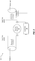
- FIG. 3 is a flowchart illustrating a configuration of a method in which the voltage to the spa's heating element may be adjusted.
- FIG. 4 is a flowchart illustrating a configuration of a method in which the voltage provided to the heating element may be optimized based on the ambient temperature and the pricing of electricity.
- FIG. 4 is a schematic diagram of a configuration of a variable voltage circuit which may be used to vary the voltage to the spa's heating element.
- FIG. 5 is a schematic diagram of another possible configuration of a variable voltage circuit which may be used to vary the voltage to the spa's heating element.
- FIG. 6 is a schematic diagram of another possible configuration of a quadrac which may be used to vary the voltage to the spa's heating element.
- FIGS. 1-2 illustrate schematic diagrams of various embodiments of a heating system 10 for utilization in a spa or pool.
- the heating system may generally comprise a heating element 12 comprising a thermistor 14 , and a circuit, generally indicated at 16 , for varying the voltage provided to the heating element. While the circuit is generally referred to as a variable voltage circuit herein, it will be appreciated that the circuit can be formed several different ways to vary the voltage supplied to the heating element.
- a microprocessor may be in communication with the thermistor, and a microcontroller/processor may be in electrical communication with the circuit to vary the voltage to the heating element. It will be appreciated that the microprocessor may be located at the thermistor, at a spa controller 18 , or any suitable combination.
- a spa controller 18 may include one or more interfaces 20 , processor(s) 22 , and memory 24 .
- the spa controller may also be programmed with one or more modules 26 to perform the functions described herein.
- a VR adjusting module 28 a heating schedule module 30 , a weather data module 32 , an electricity pricing module 34 , and/or other modules 35 may be provided as described in more detail below.
- the spa controller 18 may also be in communication with a network 38 that is in communication with one or more client devices 40 and/or third party data 50 , as described in more detail below
- the methodologies can be implemented with modules (e.g., procedures, functions, and so on) that perform the functions described herein.
- Any machine readable medium tangibly embodying instructions can be used in implementing the methodologies described herein.
- software codes and programs can be stored in a memory and executed by a processing unit.
- Memory can be implemented within the processing unit or may be external to the processing unit.
- the term “memory” refers to any type of long term, short term, volatile, nonvolatile, or other storage devices and is not to be limited to any particular type of memory or number of memories, or type of media upon which memory is stored.
- the functions may be stored as one or more instructions or code on a non-transitory computer-readable medium.
- Examples include computer-readable media encoded with a data structure and computer-readable media encoded with a computer program.
- Computer-readable media may take the form of an article of manufacturer.
- Computer-readable media includes physical computer storage media.
- a storage medium may be any available medium that can be accessed by a computer.
- such computer-readable media can comprise RAM, ROM, EEPROM, CD-ROM or other optical disk storage, magnetic disk storage or other magnetic storage devices, or any other medium that can be used to store reproduced data magnetically, while discs reproduce data optically with lasers. Combinations of the above should also be included within the scope of computer-readable media.
- FIG. 8
- a communication apparatus may include a transceiver having signals indicative of instructions and data.
- the instructions and data are configured to cause one or more processors to implement the functions outlined in the claims. That is, the communication apparatus includes transmission media with signals indicative of information to perform disclosed functions. At a first time, the transmission media included in the communication apparatus may include a first portion of the information to perform the disclosed functions, while at a second time the transmission media included in the communication apparatus may include a second portion of the information to perform the disclosed functions.
- FIG. 1 shows elements of the spa heating system, including the heating element 12 in communication with the controller 18 , the thermistor 14 in communication with the controller 18 , and the variable voltage circuit 16 in communication with the controller 18 .
- the thermistor 14 may be any suitable type of thermistor known in the art, for example, NTC thermistors, thermocouples, etc.
- the thermistor 14 may be integral to the heating element 12 , or the thermistor 14 may be formed proximal to the heating element.
- the thermistor 14 may allow the system to determine the current temperature of the heating element 12 , and also track the temperature of the heating element over time.
- the controller 18 could take steps to prevent damage to the heating element (such as an auto shut-off for the heating element, a signal sent to a client device 40 , etc.).
- the thermistor 14 may also be in communication with the spa controller 18 , such that the spa controller may be able to gather data from the thermistor 14 .
- the spa controller 18 may then be programmed to take actions based on the data, for example, through use of the VR adjusting module 28 .
- the VR adjusting module may be programmed to adjust one or more elements of the variable voltage circuit 16 to control voltage supplied to the heating element 12 . For example, if the controller 18 receives a signal from the thermistor that indicates the heating element 12 is lower than a predetermined desired temperature, the VR adjusting module 28 of the controller 18 may be programmed to send a signal to the variable voltage circuit 16 to increase the voltage being sent to the heating element (see FIG. 2 , described below).
- a voltage regulator 36 may comprise any suitable voltage regulator known in the art.
- the system may also comprise a network 38 for connection of the spa controller 18 to a client device 40 and/or third party data 50 .
- the client device 40 may be used to send heating instructions to the spa controller. For example, if a spa user decides they want to use the spa at a particular time, they may send a signal to the spa controller 18 through one or more applications via network 38 . Such instructions may include a particular temperature the spa should reach at a desired time.
- the spa controller may be connected via the network 38 to one or more sets of third party data 50 .
- Such data may include, for example, data relating to the weather, ambient air temperature proximal to the spa, data relating to the current price of electricity for the voltage source of the spa, data relating to the predicted future price of electricity, etc.
- the spa controller 18 may use such third party data 50 to further increase the efficiency of the heating of the spa.
- FIG. 2 shows another view of a system used to regulate a spa's heating element 12 .
- temperature probes 51 may be provided to measure the temperature prior to contact with the heating element and after contact with the heating element.
- a pressure sensor 58 may also be provided in connection with a heat system to measure the water flow.
- any suitable type of sensor capable of measuring water flow, etc. may be used. Where water flow is too low, the heating element may heat too quickly and cause damage to the heating element and other systems of the spa. Where there are no pressure sensors to estimate water flow, the system may use the thermistor in connection with the heating element to infer water flow. Where the temperature of the heating element 12 remains fairly constant, the system may be programmed to infer water flow past the heating element 12 .
- FIG. 3 An exemplary algorithm that may be performed by the controller 18 and/or VR adjusting module 28 is shown in FIG. 3 .
- the controller 18 may receive a signal from the thermistor 14 ( 100 ).
- the controller 18 may, through the VR adjusting module 28 or otherwise, determine a current temperature of the heating element 12 based on the signal received from the thermistor ( 105 ).
- the controller 18 may determine a current temperature of the water proximal to the heating element 12 .
- the controller 18 may, through the VR adjusting module 28 or otherwise, query to determine if the current temperature (of either the heating element 12 or the water proximal to heating element 12 as measured by temperature probe 51 ) is equal to a predetermined desired temperature ( 110 ).
- the predetermined desired temperature may be programmed into the heating schedule module 30 and stored on a memory 24 , may be determined by a user selecting a predetermined desired temperature via an interface 20 , may be determined by a user selecting a predetermined desired temperature via a client device 40 in communication with the controller 18 via a network 38 , may be determined based on third party data 50 such as weather data, or by any other suitable means.
- the algorithm may loop back to receive a signal from thermistor 14 ( 100 ) without making adjustments to the voltage sent to the heating element 12 .
- the algorithm may query if the current temperature is lower than the predetermined desired temperature (alternatively, it is appreciated the algorithm may query if the current temperature is higher than the predetermined desired temperature) ( 115 ).
- the algorithm may send a signal to increase the voltage to the heating element 12 ( 120 ), then the algorithm may loop through again to receive a signal from the thermistor ( 100 ).
- the algorithm may be programmed to send a signal to decrease the voltage to heating element 12 ( 125 ), and then continue the loop to receive a signal from the thermistor ( 100 ).
- the steps of FIG. 3 need not be taken in the specific order shown and one or more steps may be taken at the same time.
- the various modules 26 on the spa controller 18 may increase the energy efficiency of the spa's heating system.
- the heating schedule module 30 may be programmed to analyze and “learn” the heating patterns of users. If users tend to use the spa at a specific time of day, the heating schedule module 30 may allow the spa to warm up to the desired temperature more slowly and efficiently to achieve the correct temperature by the specific time of day the users tend to use the spa. Similarly, if users tend to use the spa on weekends, the heating schedule module 30 may allow the spa to keep at a cooler, more energy efficient temperature automatically during the week, and warm up to a desired use temperature in an energy-efficient manner in anticipation of the weekend use.
- the weather data module 32 may retrieve third party data 50 relating to the ambient temperature to determine the most energy efficient holding temperature of the spa while it is not in use.
- An electricity pricing module 34 may also be provided to decrease the cost to heat the water in the spa.
- an electricity pricing module may allow the controller to retrieve third party data 50 relating to the current price of electricity per kilowatt-hour. Similarly, the data may relate to the predicted future price of energy per kilowatt-hour.
- the electricity pricing module 34 may determine, based on the third party data 50 , as well as data from the heating schedule module 30 and/or instructions regarding heating from a client device 40 , the optimal time to heat the spa.
- the electricity pricing module may obtain data relating to the cost of electricity per kilowatt-hour over the next five hours and determine the best time to heat the spa. For example, if the price of energy is currently low, but is predicted to increase, the electricity pricing module may determine that the spa should be heated immediately (which requires a greater electricity draw) and then the heat be maintained (which requires less electricity draw). Conversely, if the price of electricity is currently high, but is predicted to decrease, the electricity pricing module may determine that the spa should not be heated until closer to the time that the spa will be in use.
- Other modules 35 may be provided as desired to control the heating element and such are anticipated as being within the scope of this disclosure.
- the heating schedule module 30 may be used to provide default heat settings to controller 18 , which may be overridden by user who may desire to use the spa outside the pattern established by the heating schedule module 30 .
- a user can direct the controller 18 , via interface 20 , to heat the spa.
- a user may direct the controller 18 through an interface provided on a client device 40 and through network 38 , to heat the spa.
- a heating direction When such a heating direction is given, it may be given with a directive to heat the spa in a certain amount of time. For example, if a user immediately wants to use the spa, an immediate increase in the heat may be required. Thus, a larger voltage may be sent to the heating element 12 to quickly heat the water.
- a larger heater can be used effectively to maintain a lower temperature (wherein a lower voltage is applied to the heating element 12 ) and also be used effectively to quickly heat the water (wherein a larger voltage is applied to the heating element 12 ).
- typical spa heating elements may be 2 kW, 4 kW, 4.5 kW, or 5.5 kW.
- Using a larger 5.5 kW heater where a smaller 4 kW heater is typically used will allow for faster heating when wanted.
- a larger 5.5 kW heating element would typically have the drawback of being less energy efficient when the spa is not being actively heated.
- the 5.5 kW heater could be regulated through the use of the variable voltage circuit 16 to lower the power to 2 kW or similar for a slower heating cycle using less power over a longer time.
- FIG. 4 shows a flowchart of steps which may be taken on the various modules 26 of the controller 18 in order to optimize the heating of the spa's water by controlling voltage to heating element 12 .
- the system may receive an instruction relating to heating of the spa ( 200 ).
- This instruction may come from various sources.
- the instruction may come from a user inputting a specific instruction relating to a temperature and a time from a client device 40 over network 38 , or on an interface 20 on the controller 18 .
- the instruction may come directly from the heating schedule module 30 , based on the prior history of usage of the spa in the past.
- the spa controller may receive data relating to an ambient air temperature proximal to the spa ( 205 ).
- the weather data module 32 may use such data to determine an amount of time it will take the spa to achieve the temperature desired by the desired time. For example, during colder weather, it may take longer to achieve the desired temperature and the weather data module 32 may take the ambient temperature into consideration and send appropriate instructions to the controller 18 .
- the system may then receive data relating to electricity pricing ( 210 ) from a third party data source 50 .
- the electricity pricing module 34 may receive data from a third party 50 over network 38 relating to the present cost of electricity for the electricity source of the spa.
- the electricity pricing module 34 may also receive data from a third party 50 over network 38 relating to the predicted future price of electricity for the spa's electricity source, such as the predicted price for each hour over the next 12 hours.
- the electricity pricing module 34 may store such pricing on memory 24 and compile its own predictions relating to future pricings. Based on the current and predicted future pricing of electricity, as well as the instructions received (at step 200 ), the electricity pricing module 34 may send instructions to the controller 18 to optimize the timing to heat the spa.
- the various modules may receive instructions and/or third party data, and, based on such instructions/third party data, determine the optimal timing to heat the spa ( 215 ).
- the instructions for the optimal heating time for the spa may then be sent to controller 18 , and the controller may execute such instructions, for example, through the VR adjusting module 28 .
- the steps of FIG. 4 need not be taken in the specific order shown and one or more steps may be taken at the same time. Similarly, the steps may be taken multiple times per second and the optimal timing determination ( 215 ) may be nearly continuously updated in response to changing instructions and/or third party data.
- the mechanism for controlling the variable voltage circuit 16 may be any suitable mechanism known in the art.
- FIGS. 5-6 show various configurations for variable voltage circuits which are contemplated.
- the variable voltage circuit 16 may comprise any suitable circuit to vary the voltage applied to a load (in this case, the heating element 12 ) known in the art.
- a voltage regulator may comprise any suitable voltage regulator known in the art.
- the voltage regulator comprises a variable resistor/rheostat 42 .
- the variable resistor may be in direct communication with the spa controller 18 , and the variable resistor may receive signals from the spa controller 18 , such as signals to increase the voltage ( 120 in FIG. 3 or decrease the voltage ( 125 in FIG. 3 ).
- the variable voltage circuit comprises a capacitor 44 , a variable resistor 42 , a diac 48 , and a triac 52 , in electrical communication with the heating element 12 .
- the capacitor 44 may be in electrical communication with the voltage supply, such AC from the mains power supply.
- the variable resistor 42 may be in electrical communication with the capacitor 44 and heating element 12 , and also connected to the controller 18 to receive signals from the controller 18 (for clarity, the controller is not shown in FIG. 5 ).
- the variable resistor 42 may be any suitable variable resistor known in the art.
- the variable resistor 42 may be adjusted to change the output resistance value based on instructions received from the controller 18 .
- the controller 18 may, through the VR adjusting module 28 , send a signal to the voltage regulator 36 comprising the variable resistor 42 , to increase the voltage being sent to the heating element 12 (for example, in step 120 of FIG. 3 where the algorithm sends a signal to increase the voltage to the heating element 12 ).
- the input voltage to the spa (represented by Vs in FIGS. 5-6 ) may be regulated to adjust the output voltage to the heating element 12 .
- the variable resistor 42 may be used to control a thyristor (described below) in the variable voltage circuit 16 .
- the controller 18 may send a signal to increase resistance in the variable resistor 42 or decrease resistance in the variable resistor 42 .
- the variable voltage circuit 16 may also comprise a thyristor in electrical communication with the capacitor.
- the thyristor may comprise a solid-state semiconductor device with four layers of alternating P- and N-type materials to act as a bistable switch. The thyristor conducts when its gate receives the predetermined current trigger, and continues to conduct until the voltage across the device reverses. As shown in FIGS. 5-6 , the current trigger is the voltage of the variable resistor minus the voltage of the capacitor.
- any suitable thyristor may be used in the variable voltage circuit 16 .
- the variable voltage circuit 16 includes a diac 48 which acts as a gate for a triac 52 .
- the diac 48 is a two-junction bidirectional semiconductor device designed to break down when the AC voltage across it exceeds a certain level passing current in either direction.
- the diac 48 blocks the flow of current in both directions until the applied voltage is greater than the breakdown voltage or breakover voltage V BR , at which point breakdown of the device occurs and the diac conducts heavily.
- the main terminal one (usually the anode) is labeled as MT 2
- the main terminal two (usually the cathode) is labeled as MT 1 .
- the capacitor 44 charges via the variable resistor 42 until the voltage across the capacitor is sufficient to trigger the diac 48 into conduction. Once the diac 48 is conducting, the capacitor 44 discharges into the triac 52 , and this sudden pulse of current fires the triac 52 into conduction.
- the phase angle at which the triac is triggered can be varied using the variable resistor 42 , as the variable resistor 42 controls the charging rage of the capacitor.
- the triac 52 may be configured to turn off automatically at the end of the half-cycle as the supply voltage falls to zero, reducing the current through the triac below its holding current, IH, and the diac stops conduction. The process of charging the capacitor via the variable resistor starts again at the next half-cycle.
- a quadrac 56 may also similarly be used to regulate voltage to the heating element 12 .
- a quadrac may comprise a diac and triac fabricated together within a single semiconductor package; such quadracs are also known as “internally triggered triacs,”
- the quadrac 56 may be a bi-directional device which is gate controlled using either polarity of the main terminal voltage. Thus, it may be used for full-wave phase-control applications such as the spa heating element.
- quadracs are a three-terminal semiconductor switching device labelled MT 2 for main terminal one (usually the anode), MT 1 for main terminal two (usually the cathode) and G for the gate terminal.
- variable voltage circuit may comprise an integrated circuit with a switch-mode power supply.
- the power supply may be turned on and off at very high frequencies in order to control power to the heating element 12 .
- Settings selected or inputted by a user on the user interface 20 at the spa controller 18 may not only cause the spa controller 18 to implement such settings, but may also cause the network 38 to communicate such settings to a client device 40 . In this manner, another spa user who is remote from the spa may be able to determine, in real-time, the settings on the spa controller 18 . This may provide advantages such as increased energy efficiency, and improved ease of use of the spa.
- kits may be provided that may include the variable voltage circuit to be hard-wired to a spa, as well as the controller 18 .
- embodiments of the present invention may enable for enhanced systems.
- embodiments of the present invention may increase efficiency of a system, reduce energy used by systems, increase safety of systems, and increase comfort levels of users.
Landscapes
- Health & Medical Sciences (AREA)
- Public Health (AREA)
- General Health & Medical Sciences (AREA)
- Veterinary Medicine (AREA)
- Physical Education & Sports Medicine (AREA)
- Rehabilitation Therapy (AREA)
- Life Sciences & Earth Sciences (AREA)
- Animal Behavior & Ethology (AREA)
- Epidemiology (AREA)
- Pain & Pain Management (AREA)
- Physics & Mathematics (AREA)
- Engineering & Computer Science (AREA)
- General Physics & Mathematics (AREA)
- General Engineering & Computer Science (AREA)
- Automation & Control Theory (AREA)
- Nonlinear Science (AREA)
- Control Of Resistance Heating (AREA)
Abstract
Description
Claims (19)
Priority Applications (1)
| Application Number | Priority Date | Filing Date | Title |
|---|---|---|---|
| US16/032,915 US10925805B2 (en) | 2018-07-11 | 2018-07-11 | Heating system for spa |
Applications Claiming Priority (1)
| Application Number | Priority Date | Filing Date | Title |
|---|---|---|---|
| US16/032,915 US10925805B2 (en) | 2018-07-11 | 2018-07-11 | Heating system for spa |
Publications (2)
| Publication Number | Publication Date |
|---|---|
| US20200016029A1 US20200016029A1 (en) | 2020-01-16 |
| US10925805B2 true US10925805B2 (en) | 2021-02-23 |
Family
ID=69138141
Family Applications (1)
| Application Number | Title | Priority Date | Filing Date |
|---|---|---|---|
| US16/032,915 Expired - Fee Related US10925805B2 (en) | 2018-07-11 | 2018-07-11 | Heating system for spa |
Country Status (1)
| Country | Link |
|---|---|
| US (1) | US10925805B2 (en) |
Families Citing this family (2)
| Publication number | Priority date | Publication date | Assignee | Title |
|---|---|---|---|---|
| US12222702B2 (en) * | 2021-06-03 | 2025-02-11 | Hayward Industries, Inc. | Modulating pool or spa heater systems and associated methods |
| EP4418178A1 (en) * | 2023-02-16 | 2024-08-21 | Zavepower Innovative Technology AB | Device and method for energy control of a bathing system |
Citations (26)
| Publication number | Priority date | Publication date | Assignee | Title |
|---|---|---|---|---|
| US3548157A (en) * | 1969-03-25 | 1970-12-15 | Stevens & Co Inc J P | Heating control circuit with triac-diac combination |
| US3555355A (en) * | 1968-10-31 | 1971-01-12 | Allen Bradley Co | Thermistor controlled overload protection circuit |
| US3813927A (en) * | 1973-07-16 | 1974-06-04 | L Furgason | Moisture transducer |
| US4455480A (en) * | 1981-03-10 | 1984-06-19 | Tokyo Shibaura Denki Kabushiki Kaisha | Rice cooker-warmer |
| US4675874A (en) * | 1983-02-24 | 1987-06-23 | Veb Kombinat Feinmechanische Werke Halle | Temperature stabilization of laser cavities |
| GB2290152A (en) * | 1994-06-03 | 1995-12-13 | Novomec Ltd | Control circuit for a load |
| US5585025A (en) * | 1993-09-13 | 1996-12-17 | Softub, Inc. | SPA control circuit |
| JPH11344901A (en) * | 1998-06-03 | 1999-12-14 | Canon Inc | Heating device, fixing device, and image forming apparatus provided with the heating device |
| US6246831B1 (en) * | 1999-06-16 | 2001-06-12 | David Seitz | Fluid heating control system |
| US6355913B1 (en) | 2000-05-31 | 2002-03-12 | Gecko Electronique, Inc. | Infrared sensor for hot tub spa heating element |
| WO2002053987A2 (en) * | 2001-01-02 | 2002-07-11 | Aos Holding Company | Proportional band temperature control for one or more heating elements |
| US6476363B1 (en) | 2000-09-25 | 2002-11-05 | Gecko Electronique, Inc. | Resistive water sensor for hot tub spa heating element |
| US6965815B1 (en) * | 1987-05-27 | 2005-11-15 | Bilboa Instruments, Inc. | Spa control system |
| US20060162719A1 (en) * | 2004-11-30 | 2006-07-27 | 9090-3493 Quebec Inc. | Water flow detection system for a bathing unit |
| US20060238931A1 (en) | 2005-04-22 | 2006-10-26 | Cline David J | Shutoff system for pool or spa |
| US20080041839A1 (en) * | 2004-12-01 | 2008-02-21 | Trong Tran | Spa heater system |
| US20090204263A1 (en) * | 2008-02-08 | 2009-08-13 | Chris Love | Pool temperature controller |
| US20090255049A1 (en) | 2008-04-10 | 2009-10-15 | Paul Rosenau | Bathing installation control with rfid/card reader/biometric scanner |
| US8014902B2 (en) * | 2008-02-22 | 2011-09-06 | Lawrence Kates | Method and apparatus for energy-efficient temperature-based systems management |
| CN102966765A (en) * | 2012-11-07 | 2013-03-13 | 深圳和而泰智能控制股份有限公司 | Water temperature automatic regulating device and intelligent faucet |
| US20130201316A1 (en) * | 2012-01-09 | 2013-08-08 | May Patents Ltd. | System and method for server based control |
| WO2014022843A1 (en) | 2012-08-03 | 2014-02-06 | Howell Marvin H | Spa cover |
| US20140303757A1 (en) * | 2013-03-15 | 2014-10-09 | Hayward Industries, Inc. | Modular pool/spa control system |
| US20150260428A1 (en) * | 2014-03-14 | 2015-09-17 | Joshua Haldeman | Pool water heater |
| US20170211285A1 (en) | 2016-01-22 | 2017-07-27 | Hayward Industries, Inc. | Systems and Methods for Providing Network Connectivity and Remote Monitoring, Optimization, and Control of Pool/Spa Equipment |
| US20190021944A1 (en) * | 2017-07-19 | 2019-01-24 | Jerrell Penn Hollaway | Spa control wtih novel heater management system |
-
2018
- 2018-07-11 US US16/032,915 patent/US10925805B2/en not_active Expired - Fee Related
Patent Citations (28)
| Publication number | Priority date | Publication date | Assignee | Title |
|---|---|---|---|---|
| US3555355A (en) * | 1968-10-31 | 1971-01-12 | Allen Bradley Co | Thermistor controlled overload protection circuit |
| US3548157A (en) * | 1969-03-25 | 1970-12-15 | Stevens & Co Inc J P | Heating control circuit with triac-diac combination |
| US3813927A (en) * | 1973-07-16 | 1974-06-04 | L Furgason | Moisture transducer |
| US4455480A (en) * | 1981-03-10 | 1984-06-19 | Tokyo Shibaura Denki Kabushiki Kaisha | Rice cooker-warmer |
| US4675874A (en) * | 1983-02-24 | 1987-06-23 | Veb Kombinat Feinmechanische Werke Halle | Temperature stabilization of laser cavities |
| US6965815B1 (en) * | 1987-05-27 | 2005-11-15 | Bilboa Instruments, Inc. | Spa control system |
| US5585025A (en) * | 1993-09-13 | 1996-12-17 | Softub, Inc. | SPA control circuit |
| GB2290152A (en) * | 1994-06-03 | 1995-12-13 | Novomec Ltd | Control circuit for a load |
| JPH11344901A (en) * | 1998-06-03 | 1999-12-14 | Canon Inc | Heating device, fixing device, and image forming apparatus provided with the heating device |
| US6246831B1 (en) * | 1999-06-16 | 2001-06-12 | David Seitz | Fluid heating control system |
| US6633726B2 (en) * | 1999-07-27 | 2003-10-14 | Kenneth A. Bradenbaugh | Method of controlling the temperature of water in a water heater |
| US6355913B1 (en) | 2000-05-31 | 2002-03-12 | Gecko Electronique, Inc. | Infrared sensor for hot tub spa heating element |
| US6476363B1 (en) | 2000-09-25 | 2002-11-05 | Gecko Electronique, Inc. | Resistive water sensor for hot tub spa heating element |
| WO2002053987A2 (en) * | 2001-01-02 | 2002-07-11 | Aos Holding Company | Proportional band temperature control for one or more heating elements |
| US20060162719A1 (en) * | 2004-11-30 | 2006-07-27 | 9090-3493 Quebec Inc. | Water flow detection system for a bathing unit |
| US20080041839A1 (en) * | 2004-12-01 | 2008-02-21 | Trong Tran | Spa heater system |
| US20060238931A1 (en) | 2005-04-22 | 2006-10-26 | Cline David J | Shutoff system for pool or spa |
| US20090204263A1 (en) * | 2008-02-08 | 2009-08-13 | Chris Love | Pool temperature controller |
| US8014902B2 (en) * | 2008-02-22 | 2011-09-06 | Lawrence Kates | Method and apparatus for energy-efficient temperature-based systems management |
| US20090255049A1 (en) | 2008-04-10 | 2009-10-15 | Paul Rosenau | Bathing installation control with rfid/card reader/biometric scanner |
| US20130201316A1 (en) * | 2012-01-09 | 2013-08-08 | May Patents Ltd. | System and method for server based control |
| WO2014022843A1 (en) | 2012-08-03 | 2014-02-06 | Howell Marvin H | Spa cover |
| CN102966765A (en) * | 2012-11-07 | 2013-03-13 | 深圳和而泰智能控制股份有限公司 | Water temperature automatic regulating device and intelligent faucet |
| US20140303757A1 (en) * | 2013-03-15 | 2014-10-09 | Hayward Industries, Inc. | Modular pool/spa control system |
| US20150260428A1 (en) * | 2014-03-14 | 2015-09-17 | Joshua Haldeman | Pool water heater |
| US20170211285A1 (en) | 2016-01-22 | 2017-07-27 | Hayward Industries, Inc. | Systems and Methods for Providing Network Connectivity and Remote Monitoring, Optimization, and Control of Pool/Spa Equipment |
| US20170209338A1 (en) * | 2016-01-22 | 2017-07-27 | Hayward Industries, Inc. | Systems and Methods for Providing Network Connectivity and Remote Monitoring, Optimization, and Control of Pool/Spa Equipment |
| US20190021944A1 (en) * | 2017-07-19 | 2019-01-24 | Jerrell Penn Hollaway | Spa control wtih novel heater management system |
Non-Patent Citations (7)
| Title |
|---|
| Amin et al. Design of Microcontroller Based Thyristor Controlled Three-Phase Static Volt-Ampere Reactive Compensator, 2014, 3rd International Conference on Informatics, Electronics & Vision 2014, (Year: 2014). * |
| Hlaing et al. Microcontroller-Based Single-Phase Automatic Voltage Regulator, 2010, IEEE, 222-226. (Year: 2010). * |
| Machine Translation of CN-102966765-A. (Year: 2013). * |
| Machine Translation of JP-11344901-A (Year: 1999). * |
| Skinner et al. Using Smart Sensor Strings for Continuous Monitoring of Temperature Stratification in Large Water Bodies, Dec. 2006, IEEE Sensors Journal, vol. 6 No. 6, 1473-1481. (Year: 2006). * |
| USPTO as International Searching Authority, "International Search Report and Written Opinion", for application No. PCT/US2019/019835, dated Nov. 22, 2019. |
| Wang, Kai, et al. Thermoeconomic Assessment of a PV/T Combined Heating and Power System for University Sport Centre of Bari. vol. 158, 2019. Ei Compendex®. Web. Aug. 13, 2019. (Year: 2019). * |
Also Published As
| Publication number | Publication date |
|---|---|
| US20200016029A1 (en) | 2020-01-16 |
Similar Documents
| Publication | Publication Date | Title |
|---|---|---|
| US10564660B2 (en) | Water heater energy management controller | |
| US20100089339A1 (en) | System and method for controlling a pump in a recirculating hot water system | |
| US10925805B2 (en) | Heating system for spa | |
| EP3063476B1 (en) | Temperature control apparatus, method for its operation and computer program product | |
| EP2484987B1 (en) | Heat pump hot-water supply system | |
| CA3030459C (en) | Boiler integrated control with non-linear outdoor reset methodology | |
| JP6937636B2 (en) | Hot water storage type water heater, home system, and control method | |
| FI92961C (en) | Device for room temperature control | |
| US5040725A (en) | Adaptive controller for forced hot water heating systems | |
| CN108444093B (en) | Storage and heating integrated electric water heater | |
| JPS6030928A (en) | Control device for hot water storage type electric water heater | |
| US11686503B2 (en) | Smart electric heating device | |
| JP2019011898A (en) | Bath device | |
| CN111473491A (en) | Continuously adjustable heat exchange quantity adjusting method and device and semiconductor air conditioner | |
| JPS6030930A (en) | Control device for hot water storage type electric water heater | |
| CN114623599A (en) | Water heater and go out water control system, water supply system thereof | |
| KR100469474B1 (en) | An electric boiler use a midnight elecricity | |
| JPS647302B2 (en) | ||
| FI127418B (en) | Peak heating power limiter arrangement | |
| US20230341150A1 (en) | Reheat scheduling for water heaters | |
| JP2019160639A (en) | Fuel cell system | |
| WO2026031567A1 (en) | Electric heating device and control method therefor | |
| JPS6030942A (en) | Control device of hot-water storage type electric hot-water heater | |
| JPH1047763A (en) | Hot water storage system | |
| CN121067471A (en) | Thermostatic control methods, systems, devices, equipment and storage media for water heaters |
Legal Events
| Date | Code | Title | Description |
|---|---|---|---|
| FEPP | Fee payment procedure |
Free format text: ENTITY STATUS SET TO UNDISCOUNTED (ORIGINAL EVENT CODE: BIG.); ENTITY STATUS OF PATENT OWNER: SMALL ENTITY |
|
| FEPP | Fee payment procedure |
Free format text: ENTITY STATUS SET TO SMALL (ORIGINAL EVENT CODE: SMAL); ENTITY STATUS OF PATENT OWNER: SMALL ENTITY |
|
| STPP | Information on status: patent application and granting procedure in general |
Free format text: NON FINAL ACTION MAILED |
|
| AS | Assignment |
Owner name: BULLFROG INTERNATIONAL, L.C., UTAH Free format text: ASSIGNMENT OF ASSIGNORS INTEREST;ASSIGNOR:HALES, ERIC;REEL/FRAME:051250/0128 Effective date: 20181112 |
|
| STPP | Information on status: patent application and granting procedure in general |
Free format text: RESPONSE TO NON-FINAL OFFICE ACTION ENTERED AND FORWARDED TO EXAMINER |
|
| STPP | Information on status: patent application and granting procedure in general |
Free format text: FINAL REJECTION MAILED |
|
| STPP | Information on status: patent application and granting procedure in general |
Free format text: NOTICE OF ALLOWANCE MAILED -- APPLICATION RECEIVED IN OFFICE OF PUBLICATIONS |
|
| STCF | Information on status: patent grant |
Free format text: PATENTED CASE |
|
| FEPP | Fee payment procedure |
Free format text: MAINTENANCE FEE REMINDER MAILED (ORIGINAL EVENT CODE: REM.); ENTITY STATUS OF PATENT OWNER: SMALL ENTITY |
|
| LAPS | Lapse for failure to pay maintenance fees |
Free format text: PATENT EXPIRED FOR FAILURE TO PAY MAINTENANCE FEES (ORIGINAL EVENT CODE: EXP.); ENTITY STATUS OF PATENT OWNER: SMALL ENTITY |
|
| STCH | Information on status: patent discontinuation |
Free format text: PATENT EXPIRED DUE TO NONPAYMENT OF MAINTENANCE FEES UNDER 37 CFR 1.362 |
|
| FP | Lapsed due to failure to pay maintenance fee |
Effective date: 20250223 |