US10908198B2 - Determining meter phase using interval voltage measurements - Google Patents
Determining meter phase using interval voltage measurements Download PDFInfo
- Publication number
- US10908198B2 US10908198B2 US16/055,713 US201816055713A US10908198B2 US 10908198 B2 US10908198 B2 US 10908198B2 US 201816055713 A US201816055713 A US 201816055713A US 10908198 B2 US10908198 B2 US 10908198B2
- Authority
- US
- United States
- Prior art keywords
- electric meter
- electric
- cluster
- meters
- profiles
- Prior art date
- Legal status (The legal status is an assumption and is not a legal conclusion. Google has not performed a legal analysis and makes no representation as to the accuracy of the status listed.)
- Active, expires
Links
Images


Classifications
-
- G—PHYSICS
- G01—MEASURING; TESTING
- G01R—MEASURING ELECTRIC VARIABLES; MEASURING MAGNETIC VARIABLES
- G01R21/00—Arrangements for measuring electric power or power factor
- G01R21/133—Arrangements for measuring electric power or power factor by using digital technique
- G01R21/1331—Measuring real or reactive component, measuring apparent energy
-
- G—PHYSICS
- G01—MEASURING; TESTING
- G01R—MEASURING ELECTRIC VARIABLES; MEASURING MAGNETIC VARIABLES
- G01R22/00—Arrangements for measuring time integral of electric power or current, e.g. electricity meters
- G01R22/06—Arrangements for measuring time integral of electric power or current, e.g. electricity meters by electronic methods
- G01R22/061—Details of electronic electricity meters
- G01R22/063—Details of electronic electricity meters related to remote communication
-
- G—PHYSICS
- G01—MEASURING; TESTING
- G01R—MEASURING ELECTRIC VARIABLES; MEASURING MAGNETIC VARIABLES
- G01R19/00—Arrangements for measuring currents or voltages or for indicating presence or sign thereof
- G01R19/25—Arrangements for measuring currents or voltages or for indicating presence or sign thereof using digital measurement techniques
- G01R19/2513—Arrangements for monitoring electric power systems, e.g. power lines or loads; Logging
-
- G—PHYSICS
- G01—MEASURING; TESTING
- G01R—MEASURING ELECTRIC VARIABLES; MEASURING MAGNETIC VARIABLES
- G01R31/00—Arrangements for testing electric properties; Arrangements for locating electric faults; Arrangements for electrical testing characterised by what is being tested not provided for elsewhere
- G01R31/50—Testing of electric apparatus, lines, cables or components for short-circuits, continuity, leakage current or incorrect line connections
- G01R31/66—Testing of connections, e.g. of plugs or non-disconnectable joints
- G01R31/67—Testing the correctness of wire connections in electric apparatus or circuits
-
- G—PHYSICS
- G06—COMPUTING OR CALCULATING; COUNTING
- G06Q—INFORMATION AND COMMUNICATION TECHNOLOGY [ICT] SPECIALLY ADAPTED FOR ADMINISTRATIVE, COMMERCIAL, FINANCIAL, MANAGERIAL OR SUPERVISORY PURPOSES; SYSTEMS OR METHODS SPECIALLY ADAPTED FOR ADMINISTRATIVE, COMMERCIAL, FINANCIAL, MANAGERIAL OR SUPERVISORY PURPOSES, NOT OTHERWISE PROVIDED FOR
- G06Q50/00—Information and communication technology [ICT] specially adapted for implementation of business processes of specific business sectors, e.g. utilities or tourism
- G06Q50/06—Energy or water supply
-
- G—PHYSICS
- G01—MEASURING; TESTING
- G01D—MEASURING NOT SPECIALLY ADAPTED FOR A SPECIFIC VARIABLE; ARRANGEMENTS FOR MEASURING TWO OR MORE VARIABLES NOT COVERED IN A SINGLE OTHER SUBCLASS; TARIFF METERING APPARATUS; MEASURING OR TESTING NOT OTHERWISE PROVIDED FOR
- G01D4/00—Tariff metering apparatus
- G01D4/002—Remote reading of utility meters
- G01D4/004—Remote reading of utility meters to a fixed location
Definitions
- GIS Geographic Information Systems
- Utility companies typically manually track electric meters installed in the field as well as the connectivity of the electric meters to distribution transformers. For large utility companies the number of electric meters can be upwards of a few million with distribution transformers being close to one million. Geographic Information Systems (GIS) can be used to track the phase designations for the electric meters. However, GIS are not very accurate. In addition, the actual phase designation of the electric meters and associated upstream assets may change from time to time due to work performed by line crews on the system assets. Similar problems may also exist in 3-phase distribution transformers with multiple electric meters connected to them. The phase of an individual electric meter is typically not recorded but needs to be determined for purposes of managing loading on a power grid.
- the method may include: selecting a population of electric meters; selecting a historical time range based at least in part on the selected population of electric meters; selecting an interval period; creating profiles for each electric meter in the selected population of electric meters based on the voltage measurements over one or more interval periods; calculating a correlation coefficient matrix based on the profiles; clustering the selected population of electric meters into a plurality of clusters; and determining a phase of each cluster of the plurality of clusters.
- the population of electric meters may be selected as a plurality of electric meters connected to a common voltage source, where the common voltage source may be a specified distribution transformer or feeder circuit.
- the profiles created for each electric meter may be voltage profiles or voltage change profiles.
- the clustering may include associating each electric meter with more than one cluster. Confidence factors may be calculated for each electric meter in the selected population, where the confidence factors may indicate a level of confidence that an electric meter belongs in each cluster with which it is associated.
- One cluster of the plurality of clusters for which each electric meter has a highest confidence factor may be determined, and each electric meter may be allocated to the cluster for which the electric meter has the highest confidence factor.
- a phase code of an electric meter having a highest confidence factor in the cluster may be determined, and the phase code assigned to each electric meter allocated to the cluster.
- the system may include: an electric meter; a storage device; and a head-end controller configured to communicate with the storage device and the electric meter.
- the head-end controller may be configured to: select a population of electric meters; select a historical time range based at least in part on the selected population of electric meters; select an interval period; measure voltage during a plurality of interval periods for each electric meter in the selected population of electric meters; create profiles for each electric meter in the selected population of electric meters based on the voltage measurements over one or more interval periods; calculate a correlation coefficient matrix based on the profiles; cluster the selected population of electric meters into a plurality of clusters; and determine a phase of each cluster of the plurality of clusters.
- the head-end controller may be configured to select the population of electric meters as a plurality of electric meters connected to a common voltage source, where the common voltage source may be a specified distribution transformer or feeder circuit.
- the profiles created for each electric meter may be voltage profiles or voltage change profiles.
- the head-end controller may be configured to associate each electric meter with more than one cluster, and calculate confidence factors for each electric meter in the selected population.
- the confidence factors may indicate a level of confidence that an electric meter belongs in each cluster with which it is associated.
- the head-end controller may also be configured to determine one cluster of the plurality of clusters for which each electric meter has a highest confidence factor, and to allocate each electric meter to the cluster for which the electric meter has the highest confidence factor.
- the head-end controller may be configured to determine a phase code of an electric meter having a highest confidence factor in the cluster, and assign the phase code to each electric meter allocated to the cluster.
- the various embodiments provide methods and systems that can be used to identify a number of electric meters and their associated electrical loads connected to various phases of a 3-phase power grid.
- voltage measurements over specified time intervals may be correlated with a sensor having a known phase to determine the phase of a cluster of electric meters. If the phase of a device associated with a sensor is known, then the voltages associated with the device can be used to create a profile and the profile compared to the profiles for the electric meters.
- FIG. 1 is a block diagram illustrating an electrical power distribution system according to various aspects of the present disclosure
- FIG. 2 is diagram illustrating a utility management system according to various aspects of the present disclosure
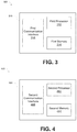
- FIG. 3 is a block diagram illustrating a head-end controller according to various aspects of the present disclosure.
- FIG. 4 is a block diagram illustrating an electric meter according to various aspects of the present disclosure
- FIG. 5 is a flowchart illustrating a method for determining electric meter phase according to various aspects of the present disclosure.
- FIG. 6 is an example of a correlation coefficient matrix according to various aspects of the present disclosure.
- FIG. 1 is a block diagram illustrating an electrical power distribution system 100 according to various aspects of the present disclosure.
- an electrical power generation facility 110 may generate electrical power.
- the generated electrical power may be, for example, 3-phase alternating current (AC) power.
- AC 3-phase alternating current
- three conductors each carry an alternating current of the same frequency and voltage amplitude relative to a common reference, but with a phase difference of one third of a cycle between each.
- the electrical power may be transmitted at high voltage (e.g., ⁇ 140-750 kV) via transmission lines 115 to an electrical power substation 120 .
- a step-down transformer 130 may step down the high voltage power to a voltage level more suitable for customer usage.
- the stepped down 3-phase power may be transmitted via feeders 140 a , 140 b , 140 c to distribution transformers 150 which may further step down the voltage (e.g., 120-240V for residential customers).
- Each distribution transformer 150 , 155 may deliver single phase and/or 3-phase power to residential and/or commercial customers.
- electrical power is delivered to the customers through electric meters 160 .
- the electric meters 160 may be supplied by the power utility company and may be connected between the loads (i.e., the customer premises) and the distribution transformers 150 , 155 .
- Three-phase transformers 155 may deliver 3-phase power, for example, to commercial customers.
- 3-phase power single phase power may be delivered from the distribution transformers 150 to various customers from different phases of the 3-phase power generated by the utility company resulting in uneven loading on the phases.
- Fuses 170 and sensors 180 may be distributed throughout the network at various assets, for example, but not limited to, feeder circuits, distribution transformers, etc.
- the fuses 170 may interrupt the circuit in the case of a circuit fault (e.g., a short circuit).
- a circuit fault e.g., a short circuit
- the sensors 180 may sense various circuit parameters, for example, frequency, voltage, current magnitude, and phase angle, to monitor operation of the network.
- sensors and fuses are merely exemplary and that sensors and/or fuses may be disposed at other locations and that additional or fewer sensors and/or fuses may be used without departing from the scope of the present disclosure.
- FIG. 2 is a diagram illustrating a utility management system 200 according to various aspects of the present disclosure.
- the utility management system 200 may include an electric meter 160 , a head-end controller 210 , and a storage device 220 . While FIG. 2 illustrates one electric meter 160 for ease of explanation, one of ordinary skill in the art will appreciate that a plurality of electric meters 160 may be included in the disclosed utility management system 200 without departing from the scope of the present disclosure.
- the electric meter 160 may monitor and/or record the energy usage at the customer premises 230 and communicate the information about energy usage to the head-end controller 210 .
- the electric meter 160 may continually monitor and record total energy usage at the customer premises 230 .
- the electric meter 160 may monitor and/or record days of the week and times of the day related to energy usage at the customer premises 230 and communicate the information to the head-end controller 210 .
- the electric meter 160 may perform as a sensor to detect and/or record abnormal measurements and/or events.
- information for example, but not limited to, average power consumed, peak power, etc., may be monitored and communicated by the electric meter 160 .
- the electric meter 160 may communicate with the head-end controller 210 via wired or wireless communication interfaces known to those of skill in the art using communication protocols appropriate to the specific communication interface. Different wired or wireless communication interfaces and associated communication protocols may be implemented on the electric meter 160 for communication with the head-end controller 210 . For example, in some embodiments a wired communication interface may be implemented, while in other embodiments a wireless communication interface may be implemented for communication between the electric meter 160 and the head-end controller 210 . In some embodiments, a wireless mesh network may connect the electric meters 160 . The electric meters 160 may transmit data to a collector (not shown) that communicates with another network to transmit the data to the head-end controller 210 . The electric meters 160 may use radio frequency (RF), cellular, or power line communication to communicate.
- RF radio frequency
- FIG. 3 is a block diagram 300 illustrating a head-end controller 210 according to various aspects of the present disclosure.
- the head-end controller 210 may control overall operation of the utility management system 200 .
- the head-end controller 210 may include a first processor 312 , a first memory 314 , and a first communications interface 316 .
- the first processor 312 may be a microprocessor; however, embodiments in accordance with the present disclosure are not limited to this implementation.
- the first processor 312 may be a microprocessor, microcomputer, computer, microcontroller, programmable controller, or other programmable device.
- the first memory 314 may be, for example, but not limited to, one or more solid state memory devices or other memory devices.
- the first memory 314 may store data and instructions for operation and control of the utility management system 200 .
- the head-end controller 210 may communicate with the electric meter 160 and the storage device 220 via the first communications interface 316 .
- Different wired or wireless communication interfaces and associated communication protocols may be implemented by the first communication interface 316 on the head-end controller 210 for communication with different devices.
- a wired communication interface may be implemented between the head-end controller 210 and the storage device 220
- a wireless communication interface may be implemented for communication between the head-end controller 210 and the electric meter 160 .
- the electric meter 160 may communicate with the head-end controller 210 via the internet or via a local gateway.
- One of ordinary skill in the art will appreciate that other communications configurations may be used without departing from the scope of the present disclosure.
- the storage device 220 may be, for example, but not limited to, one or more hard-disk drives, solid-state memory devices, or other computer-readable storage media.
- a database 225 may be stored on the storage device 220 .
- the database 225 may include data related to the number of electric meters connected to each feeder, the number of electric meters connected to each distribution transformer, the type of meter for each electric meter, the models of the electric meters, geographical locations of the electric meters, or geospatial locations of the electric meters, etc., for a plurality of electric meters in the utility management system 200 .
- the database 225 may include days of the week and times of the day correlating with load is operating information, for example, but not limited to, average power consumed by the load, peak power consumed by the load, etc.
- This information is exemplary and that other information may be included in the database 225 without departing from the scope of the present disclosure.
- FIG. 4 is a block diagram 400 illustrating an electric meter 160 according to various aspects of the present disclosure.
- the electric meter 160 may include a second processor 462 , a second memory 464 , and a second communications interface 466 .
- the electric meter 160 may monitor the load (i.e., the customer premises 230 ) and usage data of the load to the head-end controller 210 .
- the electric meter 460 may monitor the load and transmit via the second communications interface 466 the usage data of the load and/or other information to the head-end controller 210 .
- the second processor 462 may be a microprocessor; however, embodiments in accordance with the present disclosure are not limited to this implementation.
- the second processor 462 may be a microprocessor, microcomputer, computer, microcontroller, programmable controller, or other programmable device.
- the second memory 464 may be, for example, but not limited to, one or more solid state memory devices or other memory devices. The second memory 464 may store data related to operation of the load.
- the electric meter 160 may communicate with the head-end controller 210 and the customer premises 230 via the second communications interface 166 .
- Different wired or wireless communication interfaces and associated communication protocols may be implemented by the second communication interface 166 on the electric meter 160 for communication with different devices.
- a wired communication interface may be implemented between the electric meter 160 and the customer premises 230
- a wireless communication interface may be implemented for communication between the electric meter 160 and the head-end controller 210 .
- the electric meter 160 may communicate with the head-end controller 210 via the internet or via a local gateway.
- One of ordinary skill in the art will appreciate that other communications configurations may be used without departing from the scope of the present disclosure.
- FIG. 5 is a flowchart illustrating a method 500 for determining electric meter phase according to various aspects of the present disclosure.
- an electric meter population may be selected. All electric meters in a phase fed from a common voltage source are expected to show similar voltage change patterns. Selection of the electric meter population may be based on the common voltage source.
- a common voltage source may be a three phase transformer where many electric meters are connected to supply power to customers on different phases of the three phase power produced by the transformer.
- the common voltage source may be a feeder where the electric meters in the feeder are supplied by a common voltage source.
- the common voltage source may be a main feeder or primary lateral where the connectivity from the electric meters to the common voltage source is traceable.
- the relationship of the common voltage source (e.g., main feeder, primary lateral, and/or transformer bank) to the electric meter may be derived from the meter to transformer relationship or from the service location relationship defined in GIS or in the customer information system.
- a historical time range may be selected.
- the historical time range may be selected based on the availability of time-synchronized electric meter voltage profiles obtained from the utility management system for all the electric meters in the selected population.
- a historical time range having voltage profiles reported for a maximum number of meters in the selected population may be selected
- the historical time range may be a time range containing accumulated interval data received at the utility management system head-end controller from the electric meters.
- the electric meters may record the interval data, for example, every 15 minutes or another time period during a day and then send the interval data for multiple intervals to the utility management system head-end controller at a subsequent time.
- the historical time range may be greater than a day, for example, greater than a 24-hour period or another period.
- the selected historical time range may depend upon the size of the electric meter population. A longer historical time range may be selected for larger electric meter populations. For example, for an electric meter population that corresponds to electric meters connected to a distribution transformer, the historical time range may be in the range of two days to one week or another period of time. For an electric meter population corresponding to electric meters connected to a feeder (a larger number of electric meters than would be connected to a distribution transformer), the historical time range may be in the range of one week to one month or another period of time.
- an interval period for voltage measurements may be selected.
- the interval period may be used for correlation analysis. Selecting shorter interval periods may result in high frequency changes in interval period voltages being considered, while selecting longer interval periods may filter out high frequency changes in interval period voltages and take lower frequency changes in interval period voltages into consideration.
- the interval period may be in the range of 5 minutes to 2 hours or another time period. The interval period may be shorter than the historical time range.
- a profile for each electric meter may be created.
- the profile may be created by the first processor 312 in the head-end controller 210 .
- the first processor 312 may cause the profile for each electric meter to be stored in the database 225 in the storage device 220 .
- the profile may be based on voltage values.
- a profile based on voltage values may include a voltage value for each interval period during the historical time range for a particular electric meter.
- a profile based on voltage values is referred to herein as a voltage profile.
- the profile may be based on changes in voltage values.
- a profile based on changes in voltage values may include a change in voltage values for each interval period during the historical time range for a particular electric meter. The change in voltage value may be determined as a change in voltage value from one interval period to the next interval period.
- a profile based on changes in voltage values is referred to herein as a voltage change profile.
- a correlation coefficient matrix may be calculated.
- the first processor 312 in the head-end controller 210 may calculate the correlation coefficient matrix by comparing the profile of each electric meter (i.e., voltage profile or voltage change profile) with the profiles of each of the other electric meters in the selected electric meter population.
- a correlation coefficient for example, the Pearson correlation coefficient, may be calculated between two electric meters based on their voltage profiles or voltage change profiles to measure a degree of relationship between the two electric meters.
- a correlation coefficient for example, the Pearson correlation coefficient
- FIG. 6 illustrates an example of a correlation coefficient matrix 600 according to various aspect of the present disclosure.
- the low correlation coefficients for electric meter two indicate that electric meter two does not correlate with the other electric meters.
- the correlation coefficient matrix may be stored in the database 225 in the storage device 220 .
- the correlation coefficient matrix may be calculated by another processor and transmitted to the database 225 in the storage device 220 .
- an average correlation coefficient may be obtained by using multiple interval periods. This allows consideration of higher frequency or lower frequency changes.
- One of ordinary skill in the art will appreciate that other ways of calculating the correlation coefficient matrix may be used without departing from the scope of the present disclosure.
- the electric meters may be clustered.
- Each of the electric meter may be clustered into a plurality of clusters, for example, three clusters or another number of clusters.
- the number of clusters may be chosen based on number of electric phases available for the feeder. In some cases, three electric phases may be available and the electrical phases may be identified as “phase A,” “phase B,” or “phase C” with additional measurements available such as GIS assigned phase code and or sensor measurements.
- fuzzy K-means clustering may be used.
- the distance between electric meters i and j may be calculated as (1 ⁇ ij), where ⁇ ij is the correlation coefficient between electric meters i and j.
- a confidence factor for an electric meter belonging to a particular cluster may be generated, for example, by the head-end controller in the utility management system.
- an electric meter may have a different confidence factor (i.e., a different output of the standard fuzzy K-means algorithm) for each of the three clusters.
- the electric meter may be associated with the cluster where it has the highest confidence factor.
- the confidence factor indicates a level of confidence about the cluster allocation of an electric meter.
- a confidence factor threshold may be specified to determine whether or not to correct the phase code for the electric meter.
- the phase code for an electric meter may be automatically corrected based on the value of the confidence factor.
- fuzzy clustering may enable the value of the confidence factor to be used to determine whether additional verification is warranted. For example, if the confidence factor for an electric meter with respect to one cluster meets or exceeds a specified confidence factor threshold as compared to the confidence factors that do not meet the specified confidence factor threshold for the other two clusters, then no verification may be needed.
- the electric meter may be tagged with the phase code of the cluster. If the confidence factors for each of the clusters are relatively close (e.g., all are below the confidence factor threshold), additional verification may be used to verify the correct cluster for the electric meter. For example, field verification may be performed to determine the phase of the electric meter.
- the phase of each cluster may be determined.
- the electric meter with the highest confidence factor in a cluster may be selected and its profile (i.e., voltage profile or voltage change profile) may be compared to the profiles for each phase of an upstream sensor.
- An upstream sensor is a measurement device connected upstream in the distribution network to the electric meters, for example, close to.
- the sensor may have its phase code labeled and the phase code information of the sensor may be maintained by the utility company.
- the voltage profiles for each of the phases of the sensor may be correlated with the voltage profile the electric meter having the highest confidence factor in each cluster. Based on the correlation of the voltage profiles, a same phase code may be assigned to each electric meter in the cluster.
- the comparison of the profile of the electric meter and the profiles of the sensor may use correlation analysis. Based on the comparison, the cluster is determined to be associated with one of the phases.
- phase of the electric meters may be determined. If fuzzy clustering was used, then the phase of the electric meters with their highest confidence factors in a cluster may be determined to be the phase of that cluster. If non-fuzzy clustering was used, then the phase of the electric meters in a cluster is determined to be the phase of that cluster.
- phase for the clusters may be used. For example, the voltage on each phase may be changed separately and an electric meter voltage correlation analysis performed to derive the phase code of the electric meters in a cluster; field verification may be performed to verify that phase of the electric meter having the highest confidence factor in the cluster is the same as the phase of the feeder voltage source; zero-crossings for both the voltage source and the electric meters in a cluster may be compared; review historical single phase power outages and identify affected clusters of electric meters.
- phase of the electric meter having the highest confidence factor in the cluster is the same as the phase of the feeder voltage source
- zero-crossings for both the voltage source and the electric meters in a cluster may be compared
- review historical single phase power outages and identify affected clusters of electric meters may be used without departing from the scope of the present disclosure.
- interval voltage measurements since they are a more direct indicator of overall change in grid stability.
- One benefit of using interval voltage measurements instead of interval energy and power measurements is that energy and power measurements tend to indicate local consumption habits rather than distribution system conditions. In other words, consumption (i.e., energy and/or power) is driven more by the load at the customer premises, whereas voltage is driven more by the connections used to distribute electricity.
- the method 500 may be embodied on a non-transitory computer readable medium, for example, but not limited to, a memory or other non-transitory computer readable medium known to those of skill in the art, having stored therein a program including computer executable instructions for making a processor, computer, or other programmable device execute the operations of the methods.
Landscapes
- Physics & Mathematics (AREA)
- General Physics & Mathematics (AREA)
- Engineering & Computer Science (AREA)
- Business, Economics & Management (AREA)
- Power Engineering (AREA)
- Health & Medical Sciences (AREA)
- Economics (AREA)
- Water Supply & Treatment (AREA)
- Public Health (AREA)
- General Health & Medical Sciences (AREA)
- Human Resources & Organizations (AREA)
- Marketing (AREA)
- Primary Health Care (AREA)
- Strategic Management (AREA)
- Tourism & Hospitality (AREA)
- General Business, Economics & Management (AREA)
- Theoretical Computer Science (AREA)
- Remote Monitoring And Control Of Power-Distribution Networks (AREA)
Abstract
Description
Claims (20)
Priority Applications (1)
| Application Number | Priority Date | Filing Date | Title |
|---|---|---|---|
| US16/055,713 US10908198B2 (en) | 2017-08-07 | 2018-08-06 | Determining meter phase using interval voltage measurements |
Applications Claiming Priority (2)
| Application Number | Priority Date | Filing Date | Title |
|---|---|---|---|
| US201762541934P | 2017-08-07 | 2017-08-07 | |
| US16/055,713 US10908198B2 (en) | 2017-08-07 | 2018-08-06 | Determining meter phase using interval voltage measurements |
Publications (2)
| Publication Number | Publication Date |
|---|---|
| US20190041436A1 US20190041436A1 (en) | 2019-02-07 |
| US10908198B2 true US10908198B2 (en) | 2021-02-02 |
Family
ID=65229261
Family Applications (1)
| Application Number | Title | Priority Date | Filing Date |
|---|---|---|---|
| US16/055,713 Active 2038-11-15 US10908198B2 (en) | 2017-08-07 | 2018-08-06 | Determining meter phase using interval voltage measurements |
Country Status (1)
| Country | Link |
|---|---|
| US (1) | US10908198B2 (en) |
Cited By (1)
| Publication number | Priority date | Publication date | Assignee | Title |
|---|---|---|---|---|
| US11721977B2 (en) | 2020-02-25 | 2023-08-08 | Landis+Gyr Innovations, Inc. | Automatic discovery of electrical supply network topology and phase |
Families Citing this family (13)
| Publication number | Priority date | Publication date | Assignee | Title |
|---|---|---|---|---|
| US11183878B2 (en) | 2017-08-07 | 2021-11-23 | Landis+Gyr Innovations, Inc. | Maintaining connectivity information for meters and transformers located in a power distribution network |
| JP7701872B2 (en) * | 2019-03-29 | 2025-07-02 | 日本瓦斯株式会社 | Information system, information processing device, information processing method, and program |
| EP3842813A1 (en) * | 2019-12-23 | 2021-06-30 | Eneida Wireless & Sensors, S.A. | Method, device and system for the autonomous mapping of an energy meter |
| US11646602B2 (en) | 2020-03-11 | 2023-05-09 | Landis+Gyr Innovations, Inc. | Topology and phase detection for electrical supply network |
| US11515725B2 (en) | 2020-09-21 | 2022-11-29 | Landis+Gyr Innovations, Inc. | Autonomous topology validation for electrical supply network |
| EP3975363A1 (en) * | 2020-09-28 | 2022-03-30 | ABB Schweiz AG | Method and system for detecting phenomenon in electrical power network |
| CN113466578B (en) * | 2021-05-27 | 2025-03-07 | 中能瑞通(北京)科技有限公司 | A method for identifying box-meter topological relationship in rural power grid area and a method for monitoring user electricity consumption |
| EP4341644A1 (en) * | 2021-06-24 | 2024-03-27 | X Development LLC | Electrical grid monitoring using aggregated smart meter data |
| US11860210B2 (en) * | 2021-09-20 | 2024-01-02 | Itron, Inc. | Electrical phase identification using a clustering algorithm |
| CN114118304B (en) * | 2022-01-25 | 2022-06-24 | 佰聆数据股份有限公司 | User electric energy meter phase identification method, system and storage medium |
| CN114781515B (en) * | 2022-04-22 | 2025-08-22 | 南方电网科学研究院有限责任公司 | A method, device, electronic device and storage medium for phase division of distribution station area |
| CN115544323B (en) * | 2022-12-01 | 2023-04-07 | 北京志翔科技股份有限公司 | Method and device for determining phase of electric energy meter and electronic equipment |
| US20240235197A1 (en) * | 2023-01-11 | 2024-07-11 | Utilidata, Inc. | Meter-to-transformer connectivity |
Citations (45)
| Publication number | Priority date | Publication date | Assignee | Title |
|---|---|---|---|---|
| US6615147B1 (en) | 1999-08-09 | 2003-09-02 | Power Measurement Ltd. | Revenue meter with power quality features |
| US6816360B2 (en) | 1997-08-15 | 2004-11-09 | General Electric Company | Reduced cost automatic meter reading system and method using locally communicating utility meters |
| US7135850B2 (en) | 2002-09-12 | 2006-11-14 | Landis+Gyr, Inc. | Electricity meter with power supply load management |
| US7469190B2 (en) | 2005-07-01 | 2008-12-23 | Square D Company | Automated system approach to analyzing harmonic distortion in an electric power system |
| US7693670B2 (en) | 2007-08-14 | 2010-04-06 | General Electric Company | Cognitive electric power meter |
| US7990806B2 (en) | 2008-10-23 | 2011-08-02 | Hon Hai Precision Industry Co., Ltd. | Seismograph system |
| US8004933B2 (en) | 1998-08-07 | 2011-08-23 | INOVA, Ltd. | Single station wireless seismic data acquisition method and apparatus |
| US8121741B2 (en) | 2008-05-09 | 2012-02-21 | International Business Machines Corporation | Intelligent monitoring of an electrical utility grid |
| US8223466B2 (en) | 2009-06-30 | 2012-07-17 | General Electric Company | Arc flash detection |
| US20120182157A1 (en) * | 2011-01-14 | 2012-07-19 | Jim Carr | Process, Device and System For Volt/VAR Optimization |
| US8322215B2 (en) | 2010-09-13 | 2012-12-04 | Itron, Inc. | Accelerometer based removal and inversion tamper detection and tap switch feature |
| US8326554B2 (en) | 2009-12-31 | 2012-12-04 | General Electric Company | Systems, methods, and apparatus for utility meter phase identification |
| US20140005853A1 (en) * | 2012-06-27 | 2014-01-02 | Industrial Technology Research Institute | Method and system for monitoring electrical load of electric devices |
| US8635036B2 (en) | 2011-01-04 | 2014-01-21 | General Electric Company | Systems, methods, and apparatus for providing energy management utilizing a power meter |
| US8754634B2 (en) | 2011-11-14 | 2014-06-17 | General Electric Company | System and method for tamper detection in a utility meter |
| US8830083B2 (en) | 2011-05-25 | 2014-09-09 | General Electric Company | Utility meter with temperature based actuation of a remote disconnect switch |
| US8854217B2 (en) | 2013-02-13 | 2014-10-07 | Sensus Spectrum Llc | Method and apparatus for operating an electricity meter |
| US8947246B2 (en) | 2011-09-07 | 2015-02-03 | General Electric Company | Utility meter arc detection system |
| US20150052088A1 (en) | 2013-08-15 | 2015-02-19 | International Business Machines Corporation | Voltage-Based Clustering to Infer Connectivity Information in Smart Grids |
| US8978443B2 (en) | 2010-09-02 | 2015-03-17 | Landis+Gyr Inc. | Shock detection in a utility meter having reporting capability |
| US8996144B2 (en) | 2011-10-06 | 2015-03-31 | General Electric Company | Remote disconnect switch assembly |
| US20150241482A1 (en) | 2014-02-25 | 2015-08-27 | Itron, Inc. | Smart Grid Topology Estimator |
| US9164135B2 (en) | 2011-09-13 | 2015-10-20 | Honeywell International Inc. | System and method for measuring phase attributes of electrical grid system and equipment using a smart probe |
| US9304014B2 (en) | 2012-10-08 | 2016-04-05 | General Electric Company | Systems and methods for temperature compensation in a utility meter |
| US9341686B2 (en) | 2010-10-26 | 2016-05-17 | MultiDimension Technology Co., Ltd. | Single-package power meter |
| US9476740B2 (en) | 2014-09-18 | 2016-10-25 | Mueller International, Llc | Reverse flow detection and annunciation |
| US9557392B2 (en) | 2010-01-29 | 2017-01-31 | Centre National De La Recherche Scientifique | Integrated magnetometer and its manufacturing process |
| US9568522B2 (en) | 2014-10-20 | 2017-02-14 | Itron, Inc. | Electrical phase identification |
| US9602895B2 (en) | 2013-11-14 | 2017-03-21 | Microchip Technology Incorporated | Integrated circuit device with tamper detection input and having real time clock calendar logging thereof |
| US9671254B2 (en) | 2014-09-18 | 2017-06-06 | Mueller International, Llc | Magnetic sensing to detect tampering with a utility meter |
| US9891088B2 (en) | 2014-09-18 | 2018-02-13 | Mueller International, Llc | Real-time flow compensation in usage accumulation |
| US20180073910A1 (en) | 2015-01-14 | 2018-03-15 | MultiDimension Technology Co., Ltd. | Direct-read meter capable of eliminating magnetic interference of adjacent rotating wheels |
| US20180106640A1 (en) | 2016-10-14 | 2018-04-19 | Pacific Gas And Electric Company | Smart energy and data/information metering system and method |
| WO2018072030A1 (en) | 2016-10-19 | 2018-04-26 | Weir-Jones Engineering Consultants Ltd. | Systems and methods for early warning of seismic events |
| WO2018083902A1 (en) | 2016-11-01 | 2018-05-11 | オムロン株式会社 | Electricity meter and electricity meter fire outbreak location identification method |
| US20190041445A1 (en) | 2017-08-07 | 2019-02-07 | Landis+Gyr Innovations, Inc. | Maintaining connectivity information for meters and transformers located in a power distribution network |
| US20190041439A1 (en) | 2017-08-04 | 2019-02-07 | Sensus Spectrum, Llc | Method and system for high temperature detection in electric meters |
| WO2019026791A1 (en) | 2017-08-01 | 2019-02-07 | ローム株式会社 | Vibration-sensitive module |
| US10240961B2 (en) | 2013-04-18 | 2019-03-26 | Multidimension Technology Co. Ltd | Electronic water meter |
| US20190094329A1 (en) | 2017-09-28 | 2019-03-28 | Landis+Gyr Llc | Detection of deteriorated electrical connections in a meter using adjusted temperature sensing |
| US20190101411A1 (en) | 2017-09-26 | 2019-04-04 | Pacific Gas And Electric Company | Resource meter system and method |
| US10254315B2 (en) | 2013-12-25 | 2019-04-09 | Kabushiki Kaisha Toshiba | Current sensor, current measuring module, and smart meter |
| US20190129368A1 (en) * | 2016-04-29 | 2019-05-02 | Katholieke Universiteit Leuven | Cluster control of heterogeneous clusters of thermostatically controlled loads using tracker devices |
| US10295578B2 (en) | 2014-11-06 | 2019-05-21 | Kabushiki Kaisha Toshiba | Current sensor and smart meter |
| US20190219618A1 (en) | 2018-01-16 | 2019-07-18 | Pacific Gas And Electric Company | Multi-purpose (multi-dwelling) electric metering system and method |
-
2018
- 2018-08-06 US US16/055,713 patent/US10908198B2/en active Active
Patent Citations (46)
| Publication number | Priority date | Publication date | Assignee | Title |
|---|---|---|---|---|
| US6816360B2 (en) | 1997-08-15 | 2004-11-09 | General Electric Company | Reduced cost automatic meter reading system and method using locally communicating utility meters |
| US8004933B2 (en) | 1998-08-07 | 2011-08-23 | INOVA, Ltd. | Single station wireless seismic data acquisition method and apparatus |
| US6615147B1 (en) | 1999-08-09 | 2003-09-02 | Power Measurement Ltd. | Revenue meter with power quality features |
| US7135850B2 (en) | 2002-09-12 | 2006-11-14 | Landis+Gyr, Inc. | Electricity meter with power supply load management |
| US7469190B2 (en) | 2005-07-01 | 2008-12-23 | Square D Company | Automated system approach to analyzing harmonic distortion in an electric power system |
| US7693670B2 (en) | 2007-08-14 | 2010-04-06 | General Electric Company | Cognitive electric power meter |
| US8121741B2 (en) | 2008-05-09 | 2012-02-21 | International Business Machines Corporation | Intelligent monitoring of an electrical utility grid |
| US7990806B2 (en) | 2008-10-23 | 2011-08-02 | Hon Hai Precision Industry Co., Ltd. | Seismograph system |
| US8223466B2 (en) | 2009-06-30 | 2012-07-17 | General Electric Company | Arc flash detection |
| US8326554B2 (en) | 2009-12-31 | 2012-12-04 | General Electric Company | Systems, methods, and apparatus for utility meter phase identification |
| US9557392B2 (en) | 2010-01-29 | 2017-01-31 | Centre National De La Recherche Scientifique | Integrated magnetometer and its manufacturing process |
| US8978443B2 (en) | 2010-09-02 | 2015-03-17 | Landis+Gyr Inc. | Shock detection in a utility meter having reporting capability |
| US8322215B2 (en) | 2010-09-13 | 2012-12-04 | Itron, Inc. | Accelerometer based removal and inversion tamper detection and tap switch feature |
| US9341686B2 (en) | 2010-10-26 | 2016-05-17 | MultiDimension Technology Co., Ltd. | Single-package power meter |
| US8635036B2 (en) | 2011-01-04 | 2014-01-21 | General Electric Company | Systems, methods, and apparatus for providing energy management utilizing a power meter |
| US20120182157A1 (en) * | 2011-01-14 | 2012-07-19 | Jim Carr | Process, Device and System For Volt/VAR Optimization |
| US8830083B2 (en) | 2011-05-25 | 2014-09-09 | General Electric Company | Utility meter with temperature based actuation of a remote disconnect switch |
| US8947246B2 (en) | 2011-09-07 | 2015-02-03 | General Electric Company | Utility meter arc detection system |
| US9164135B2 (en) | 2011-09-13 | 2015-10-20 | Honeywell International Inc. | System and method for measuring phase attributes of electrical grid system and equipment using a smart probe |
| US9887051B2 (en) | 2011-10-06 | 2018-02-06 | Aclara Meters Llc | Remote disconnect switch assembly |
| US8996144B2 (en) | 2011-10-06 | 2015-03-31 | General Electric Company | Remote disconnect switch assembly |
| US8754634B2 (en) | 2011-11-14 | 2014-06-17 | General Electric Company | System and method for tamper detection in a utility meter |
| US20140005853A1 (en) * | 2012-06-27 | 2014-01-02 | Industrial Technology Research Institute | Method and system for monitoring electrical load of electric devices |
| US9304014B2 (en) | 2012-10-08 | 2016-04-05 | General Electric Company | Systems and methods for temperature compensation in a utility meter |
| US8854217B2 (en) | 2013-02-13 | 2014-10-07 | Sensus Spectrum Llc | Method and apparatus for operating an electricity meter |
| US10240961B2 (en) | 2013-04-18 | 2019-03-26 | Multidimension Technology Co. Ltd | Electronic water meter |
| US20150052088A1 (en) | 2013-08-15 | 2015-02-19 | International Business Machines Corporation | Voltage-Based Clustering to Infer Connectivity Information in Smart Grids |
| US9602895B2 (en) | 2013-11-14 | 2017-03-21 | Microchip Technology Incorporated | Integrated circuit device with tamper detection input and having real time clock calendar logging thereof |
| US10254315B2 (en) | 2013-12-25 | 2019-04-09 | Kabushiki Kaisha Toshiba | Current sensor, current measuring module, and smart meter |
| US20150241482A1 (en) | 2014-02-25 | 2015-08-27 | Itron, Inc. | Smart Grid Topology Estimator |
| US9891088B2 (en) | 2014-09-18 | 2018-02-13 | Mueller International, Llc | Real-time flow compensation in usage accumulation |
| US9476740B2 (en) | 2014-09-18 | 2016-10-25 | Mueller International, Llc | Reverse flow detection and annunciation |
| US9671254B2 (en) | 2014-09-18 | 2017-06-06 | Mueller International, Llc | Magnetic sensing to detect tampering with a utility meter |
| US9568522B2 (en) | 2014-10-20 | 2017-02-14 | Itron, Inc. | Electrical phase identification |
| US10295578B2 (en) | 2014-11-06 | 2019-05-21 | Kabushiki Kaisha Toshiba | Current sensor and smart meter |
| US20180073910A1 (en) | 2015-01-14 | 2018-03-15 | MultiDimension Technology Co., Ltd. | Direct-read meter capable of eliminating magnetic interference of adjacent rotating wheels |
| US20190129368A1 (en) * | 2016-04-29 | 2019-05-02 | Katholieke Universiteit Leuven | Cluster control of heterogeneous clusters of thermostatically controlled loads using tracker devices |
| US20180106640A1 (en) | 2016-10-14 | 2018-04-19 | Pacific Gas And Electric Company | Smart energy and data/information metering system and method |
| WO2018072030A1 (en) | 2016-10-19 | 2018-04-26 | Weir-Jones Engineering Consultants Ltd. | Systems and methods for early warning of seismic events |
| WO2018083902A1 (en) | 2016-11-01 | 2018-05-11 | オムロン株式会社 | Electricity meter and electricity meter fire outbreak location identification method |
| WO2019026791A1 (en) | 2017-08-01 | 2019-02-07 | ローム株式会社 | Vibration-sensitive module |
| US20190041439A1 (en) | 2017-08-04 | 2019-02-07 | Sensus Spectrum, Llc | Method and system for high temperature detection in electric meters |
| US20190041445A1 (en) | 2017-08-07 | 2019-02-07 | Landis+Gyr Innovations, Inc. | Maintaining connectivity information for meters and transformers located in a power distribution network |
| US20190101411A1 (en) | 2017-09-26 | 2019-04-04 | Pacific Gas And Electric Company | Resource meter system and method |
| US20190094329A1 (en) | 2017-09-28 | 2019-03-28 | Landis+Gyr Llc | Detection of deteriorated electrical connections in a meter using adjusted temperature sensing |
| US20190219618A1 (en) | 2018-01-16 | 2019-07-18 | Pacific Gas And Electric Company | Multi-purpose (multi-dwelling) electric metering system and method |
Non-Patent Citations (6)
| Title |
|---|
| Arya et al., "Phase Identification in Smart Grids", IEEE International Conference on Smart Grid Communications (SmartGridComm), Brussels, 2011, pp. 25-30. |
| Byun et al., "Cable and Phase Identification based on Power Line Communication", International Journal of Control and Automation, vol. B, No. 9, 2015, pp. 63-74. |
| Power Systems Integrity, Inc., "Live Line Phase Identification-Phase ID 6000", available online at http://www.psinteg.com/Phase_ID.html at least as early as Feb. 2020, 2 pages. |
| Power Systems Integrity, Inc., "Live Line Phase Identification—Phase ID 6000", available online at http://www.psinteg.com/Phase_ID.html at least as early as Feb. 2020, 2 pages. |
| Short , "Advanced Metering for Phase Identification, Transformer Identification, and Secondary Modeling", IEEE Transactions on Smart Grid, vol. 4, No. 2, Jun. 2013, pp. 651-658. |
| U.S. Appl. No. 16/057,178, Non-Final Office Action dated Jul. 13, 2020, 13 pages. |
Cited By (1)
| Publication number | Priority date | Publication date | Assignee | Title |
|---|---|---|---|---|
| US11721977B2 (en) | 2020-02-25 | 2023-08-08 | Landis+Gyr Innovations, Inc. | Automatic discovery of electrical supply network topology and phase |
Also Published As
| Publication number | Publication date |
|---|---|
| US20190041436A1 (en) | 2019-02-07 |
Similar Documents
| Publication | Publication Date | Title |
|---|---|---|
| US10908198B2 (en) | Determining meter phase using interval voltage measurements | |
| US9189822B2 (en) | Process, device and system for mapping transformers to meters and locating non-technical line losses | |
| US9292794B2 (en) | Voltage-based clustering to infer connectivity information in smart grids | |
| Banerjee et al. | Reliability based optimum location of distributed generation | |
| US9702730B2 (en) | Systems and methods for estimating conservation allocation with partial AMI | |
| US11145012B2 (en) | Using cyber-physical system-enabled microgrid system for optimal power utilization and supply strategy | |
| US20180123391A1 (en) | System and Method for Dynamic Measurement and Control of Synchronized Remote Energy Resources | |
| Hoogsteyn et al. | Low voltage customer phase identification methods based on smart meter data | |
| TWI805563B (en) | Monitoring system, computer software, and method for use in an electric power grid | |
| JP2012182979A (en) | System and method for load forecasting | |
| US10655984B2 (en) | Power state estimation for power grid serviced premises | |
| JP2013162666A (en) | Load estimation device | |
| US10547174B2 (en) | Ranking network assets based on downstream events and measurements | |
| JP2018160990A (en) | Load management apparatus and method | |
| KR101918625B1 (en) | System and method for providing power service to a plurality of customers using an energy storage device | |
| KR101744576B1 (en) | Power dissipation operation system using small and medium distributed ess | |
| JP5560828B2 (en) | Transformer load estimation method | |
| JP7140569B2 (en) | Photovoltaic power generation output estimation device and output estimation method | |
| Bessa | Solar power forecasting for smart grids considering ICT constraints | |
| JP2015139322A (en) | power network system | |
| US11061056B2 (en) | Voltage rating validator for advanced metering | |
| WO2018144009A1 (en) | Power management methods for a circuit of a substation, and related apparatuses and computer program products | |
| CN106415971B (en) | Power generation amount estimation device and power generation amount estimation method | |
| Bernards et al. | Incorporating the smart grid concept in network planning practices | |
| Chakraborty | Estimation error analysis due to aggregation interval |
Legal Events
| Date | Code | Title | Description |
|---|---|---|---|
| FEPP | Fee payment procedure |
Free format text: ENTITY STATUS SET TO UNDISCOUNTED (ORIGINAL EVENT CODE: BIG.); ENTITY STATUS OF PATENT OWNER: LARGE ENTITY |
|
| STPP | Information on status: patent application and granting procedure in general |
Free format text: DOCKETED NEW CASE - READY FOR EXAMINATION |
|
| STPP | Information on status: patent application and granting procedure in general |
Free format text: NON FINAL ACTION MAILED |
|
| STPP | Information on status: patent application and granting procedure in general |
Free format text: RESPONSE TO NON-FINAL OFFICE ACTION ENTERED AND FORWARDED TO EXAMINER |
|
| AS | Assignment |
Owner name: LANDIS+GYR INNOVATIONS, INC., GEORGIA Free format text: ASSIGNMENT OF ASSIGNORS INTEREST;ASSIGNORS:KULOOR, SOORYA;PROCTOR, KELVIN;KULOOR, CHETHANA;AND OTHERS;SIGNING DATES FROM 20170814 TO 20170825;REEL/FRAME:053171/0251 |
|
| STPP | Information on status: patent application and granting procedure in general |
Free format text: NOTICE OF ALLOWANCE MAILED -- APPLICATION RECEIVED IN OFFICE OF PUBLICATIONS |
|
| STPP | Information on status: patent application and granting procedure in general |
Free format text: NOTICE OF ALLOWANCE MAILED -- APPLICATION RECEIVED IN OFFICE OF PUBLICATIONS |
|
| STCF | Information on status: patent grant |
Free format text: PATENTED CASE |
|
| AS | Assignment |
Owner name: LANDIS+GYR TECHNOLOGY, INC., GEORGIA Free format text: MERGER;ASSIGNOR:LANDIS+GYR INNOVATIONS, INC.;REEL/FRAME:065383/0120 Effective date: 20230109 |
|
| MAFP | Maintenance fee payment |
Free format text: PAYMENT OF MAINTENANCE FEE, 4TH YEAR, LARGE ENTITY (ORIGINAL EVENT CODE: M1551); ENTITY STATUS OF PATENT OWNER: LARGE ENTITY Year of fee payment: 4 |