US10897970B2 - Luggage article with loop-shaped wheel bracket - Google Patents
Luggage article with loop-shaped wheel bracket Download PDFInfo
- Publication number
- US10897970B2 US10897970B2 US15/085,139 US201615085139A US10897970B2 US 10897970 B2 US10897970 B2 US 10897970B2 US 201615085139 A US201615085139 A US 201615085139A US 10897970 B2 US10897970 B2 US 10897970B2
- Authority
- US
- United States
- Prior art keywords
- wheel
- luggage
- wheels
- wheel bracket
- bracket
- Prior art date
- Legal status (The legal status is an assumption and is not a legal conclusion. Google has not performed a legal analysis and makes no representation as to the accuracy of the status listed.)
- Active, expires
Links
Images


Classifications
-
- A—HUMAN NECESSITIES
- A45—HAND OR TRAVELLING ARTICLES
- A45C—PURSES; LUGGAGE; HAND CARRIED BAGS
- A45C5/00—Rigid or semi-rigid luggage
- A45C5/14—Rigid or semi-rigid luggage with built-in rolling means
-
- A—HUMAN NECESSITIES
- A45—HAND OR TRAVELLING ARTICLES
- A45C—PURSES; LUGGAGE; HAND CARRIED BAGS
- A45C13/00—Details; Accessories
-
- B—PERFORMING OPERATIONS; TRANSPORTING
- B60—VEHICLES IN GENERAL
- B60B—VEHICLE WHEELS; CASTORS; AXLES FOR WHEELS OR CASTORS; INCREASING WHEEL ADHESION
- B60B33/00—Castors in general; Anti-clogging castors
- B60B33/0002—Castors in general; Anti-clogging castors assembling to the object, e.g. furniture
-
- B—PERFORMING OPERATIONS; TRANSPORTING
- B60—VEHICLES IN GENERAL
- B60B—VEHICLE WHEELS; CASTORS; AXLES FOR WHEELS OR CASTORS; INCREASING WHEEL ADHESION
- B60B33/00—Castors in general; Anti-clogging castors
- B60B33/04—Castors in general; Anti-clogging castors adjustable, e.g. in height; linearly shifting castors
- B60B33/045—Castors in general; Anti-clogging castors adjustable, e.g. in height; linearly shifting castors mounted resiliently, by means of dampers
-
- B—PERFORMING OPERATIONS; TRANSPORTING
- B60—VEHICLES IN GENERAL
- B60B—VEHICLE WHEELS; CASTORS; AXLES FOR WHEELS OR CASTORS; INCREASING WHEEL ADHESION
- B60B2200/00—Type of product being used or applied
- B60B2200/40—Articles of daily use
- B60B2200/45—Suitcases
Definitions
- the present disclosure relates generally to a wheeled luggage article and particularly to a luggage article with a loop-shaped wheel bracket.
- Luggage items and in particular luggage cases conventionally include wheels attached to the case to allow the case to be pulled along. Brackets attach the wheels to the cases.
- Each bracket supports one or more wheels and generally permits the one or more wheels to rotate about a horizontal axis.
- Each bracket may be fixed about a vertical axis to prevent the one or more wheels from swivelling about the vertical axis (generally referred to as fixed wheels) or may be rotational about the vertical axis to permit swivelling of the one or more wheels about the vertical axis (generally referred to as spinner wheels).
- wheels and wheel assemblies for luggage articles presents a particular unique challenge. Specifically the wheels have to be robust enough to withstand use under heavy loading of the case and transport over rough surface as well as when the case is dropped on its wheels. On the other hand the wheels must also be light and compact so as to maximize the weight and volume that the luggage article can carry for a given overall size and weight. The wheels must also be simple and relatively cheap to produce and assemble to minimize cost.
- a further problem that has been identified with conventional cases is that the wheel brackets generally transfer shock loads from the wheels to the cases and may be noisy as well. As such, the shock loads commonly are transferred through the case, disturb the arrangement of one's belongings, and/or cause damage to the belongings. The noise may be an annoyance and may make the use of the luggage case unpleasant.
- Documents that may be related to the present disclosure in that they include various wheel brackets are: CN102578778, CN201194600, CN201675239, CN202278929, CN202407510, CN20528768, EP001175822-0002, EP0051995, US20110168508, U.S. Pat. Nos. 2,738,542, 2,914,340, 2,923,961, 2,942,290, 2,987,752, 4,392,668, 4,422,212, and 6,478,315.
- the present disclosure advantageously provides a luggage article with a shock absorbing wheel bracket having a loop-shaped profile.
- the wheel bracket may have an open-loop or closed-loop shape, and in some examples may have a generally C-shape profile.
- the wheel bracket may include an upper end portion that is attached to the luggage article and a lower end portion that is attached to the one or more wheels.
- the wheel bracket may include a spring member, such as a leaf spring, which may be overmoulded with a plastic material.
- the wheel bracket advantageously may provide improved shock absorption and/or rolling noise reduction compared to conventional luggage articles.
- a luggage article having a loop-shaped wheel bracket includes a luggage wheel assembly having a wheel bracket attached to and extending from the luggage article.
- the luggage article may also include one or more wheels attached to the wheel bracket.
- the wheel bracket includes a spring member having a loop-shaped profile and the one or more wheels are rotationally attached to a lower end of the loop-shaped spring member.
- the wheel bracket is rotationally attached to the luggage article. In some examples, the wheel bracket is attached to the luggage article at a location on an upper arm of the spring member. In some examples, the wheel bracket is attached to the luggage article at an intermediate position or proximate an end portion of the upper arm.
- the luggage wheel assembly has a loop-shaped spring member which includes a lower arm that is integrally formed with the upper arm and defines a transition.
- the lower arm may extend radially inwardly from the transition toward a rotational axis of the one or more wheels.
- the transition defines an apex.
- the upper and lower arms extend from the transition or apex at an angle of between 0 and 90 degrees, and preferably between 30 and 60 degrees.
- the luggage wheel assembly includes a loop-shaped spring member.
- the loop shaped spring member is selected from a metal leaf spring, a steel leaf spring, a titanium leaf spring, a polymeric leaf spring, a carbon-fiber-reinforced composite leaf spring, or a combination thereof.
- the wheel bracket further includes a coating that surrounds the loop-shaped spring member.
- the coating forms a hub at a lower end of the loop-shaped spring member for attaching the one or more wheels to the wheel bracket.
- the coating forms a spinner wheel axle housing at an intermediate portion of an upper arm of the loop-shaped spring member.
- the spinner axle housing defines a swivel axis about which the wheel bracket spins relative to the luggage article.
- the luggage wheel assembly includes a spring member defining one or more engagement features that receives a portion of the coating to form a mechanical attachment between the spring member and the coating.
- At least one portion of the upper arm of the spring member extends substantially horizontally or extends substantially uniformly about a portion of the outer circumference of the one or more wheels.
- the wheel bracket may be attached to the luggage article at the at least one portion, where the at least one portion is a substantial portion of the upper arm.
- the wheel bracket of the luggage wheel assembly is attached to the luggage article adjacent the transition of the spring member or distal to the transition at a distance that is substantially the length of the upper arm.
- an effective arm length defined by the upper arm may be substantially greater than, or greater than, or less than, or substantially less than an effective arm length defined by the lower arm.
- at least one portion of the lower arm of the spring member extends to form a curve, a substantially straight length, or a twisted shape.
- the rotational axis of the one or more wheels is substantially parallel to or substantially at a right angle to a surface of the upper arm and/or the lower arm of the spring member.
- the luggage wheel assembly may have at least one portion of the lower arm of the spring member oriented substantially parallel to the one or more wheels or oriented substantially perpendicular to the rotational axis of the one or more wheels. In some examples, at least a portion of the lower arm is twisted such that at least one end portion of the lower arm distal to the transition of the spring member is oriented substantially parallel to the one or more wheels or is oriented substantially perpendicular to the rotational axis of the one or more wheels.
- At least one end portion of the lower arm defines a hub for attaching the one or more wheels.
- the luggage wheel assembly includes a wheel bracket that forms one or more wheel abutments adapted to contact an outer circumferential surface of the one or more wheels to limit the deformation of the loop-shaped spring member.
- the one or more wheels comprise one wheel or two wheels.
- the wheel bracket is located between a pair of wheels or the wheel bracket includes laterally-spaced apart tines that extend along opposite sides of a single wheel.
- the luggage wheel assembly includes a wheel bracket and the one or more wheels of the wheel bracket form part of a spinner wheel assembly.
- the loop-shaped profile of the spring member is an open loop profile or a closed loop profile.
- the spring member having the open loop profile is a C-shaped spring member.
- the spring member having the closed loop profile is an O-shaped or oval-shaped or D-shaped spring member.
- a luggage article includes one or more luggage wheel assemblies as described herein.
- the luggage article includes a plurality of walls together defining an outer structure of the luggage article, and the one or more luggage wheel assemblies are attached to and extend from one of the walls.
- FIG. 1 is a schematic front perspective view of a luggage article according to a first example
- FIG. 2 is a schematic rear view of a luggage article shown in FIG. 1 ;
- FIG. 3 is a schematic front perspective view of a wheel assembly of a luggage article shown in FIG. 1 ;
- FIG. 4 is a schematic rear perspective view of a bracket of a wheel assembly shown in FIG. 3 of a luggage article shown in FIG. 1 ;
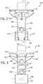
- FIG. 5 is a schematic front elevation view of a bracket of a wheel assembly shown in FIG. 3 of a luggage article shown in FIG. 1 ;
- FIG. 6 is a schematic rear elevation view of a bracket of a wheel assembly shown in FIG. 3 of a luggage article shown in FIG. 1 ;
- FIG. 7 is a schematic cross-sectional view of a bracket of a wheel assembly shown in FIG. 3 of a luggage article shown in FIG. 1 that is taken along the line 7 - 7 shown in FIG. 5 ;
- FIG. 8 is a schematic front perspective view of a spring member of a bracket shown in FIG. 4 of a wheel assembly shown in FIG. 3 of a luggage article shown in FIG. 1 ;
- FIG. 9 is a schematic side elevation view of a bracket of a wheel assembly shown in FIG. 3 of a luggage article shown in FIG. 1 with a wheel attached to the bracket;
- FIG. 10 is a schematic rear perspective view of a wheel bracket of a luggage article according to a second example
- FIG. 11 is a schematic rear perspective view of a wheel bracket of a luggage article according to a second example
- FIG. 12 is a schematic rear perspective view of a wheel bracket of a luggage article according to a third example.
- FIG. 13 is a schematic rear perspective view of a wheel bracket of a luggage article according to a third example.
- FIG. 14 is a schematic rear perspective view of a wheel assembly of a luggage article according to a fourth example; one wheel is removed to show a wheel bracket;
- FIG. 15 is a schematic front elevation view of a wheel assembly shown in FIG. 14 with both wheels attached;
- FIG. 16 is a schematic rear perspective view of a wheel assembly of a luggage article according to a fifth example; one wheel is removed to show a wheel bracket;
- FIG. 17 is a schematic front elevation view of a wheel assembly shown in FIG. 16 with both wheels attached;
- FIG. 18 is a schematic rear perspective view of a wheel bracket of a luggage article according to a sixth example.
- FIG. 19 is a schematic front elevation view of a wheel assembly shown in FIG. 18 with both wheels attached.
- FIG. 20 is a schematic rear perspective view of the wheel bracket of FIG. 18 .
- a wheeled luggage article 100 includes a generally cuboid structure 105 formed from a plurality of walls 102 , 104 , 106 , 108 , 110 , 112 defining an enclosed internal volume of the luggage article 100 in which to carry a user's belongings.
- the luggage article 100 includes opposing front and rear walls 102 , 104 , opposing side walls 106 , 108 , and opposing top and bottom end walls 110 , 112 that collectively define a housing or outer structure 105 of the article 100 .
- the luggage article 100 may be a bag, a case, or other luggage articles.
- the luggage article 100 may be hard and/or soft sided.
- the luggage article 100 may be split along an opening line 114 into a lid section 116 , which includes the front wall 102 , and a base section 118 , which includes the rear wall 104 .
- the lid section 116 may be connected to the base section 118 along a portion of a side of the article 100 via a hinge 120 in a conventional manner, and the luggage article 100 may be opened at the opening line 114 to access the internal volume.
- the hinge 120 may be formed of a zipper 122 and a fabric strip, a piano hinge, discrete hinges spaced apart, or an articulating joint.
- the piano hinge, the discrete hinges, or the articulating joint may be made from metal, plastic, any other suitable material, or any combination thereof.
- the hinge 120 may be stitched to the lid 116 and also to the base 118 , or may be coupled in another suitable manner.
- a zipper 122 along a periphery of the opening line 114 or other conventional closure arrangement, for example clamp locks, may secure the lid section 116 to the base section 118 to close the luggage article 100 .
- the luggage article 100 may include at least one handle.
- the depicted luggage article 100 includes a telescoping tow handle 124 associated with the top wall 112 .
- the depicted case also includes fixed carry handles 126 attached to the top wall 112 and the side wall 106 .
- the telescoping handle 124 and the fixed carry handles 126 may be associated with any wall of the luggage article 100 .
- the luggage article 100 may include at least one wheel assembly 128 .
- the depicted luggage article 100 includes four wheel assemblies 128 mounted from the bottom end wall 110 of the case 110 .
- Each spinner wheel assembly 128 is located proximate a bottom end corner of the luggage article 100 .
- each spinner wheel assembly 128 is located on the bottom end wall 110 of the case near an intersection of one of the front and rear walls 102 , 104 and one of the side walls 106 , 108 of the luggage article 100 .
- the spinner wheel assemblies 128 may be spaced apart from one another by substantially the width and/or depth of the luggage article 100 .
- each spinner wheel assembly 128 may include a wheel mount 130 , one or more wheels 132 , and a wheel bracket 134 .
- the wheel mount 130 generally attaches the wheel bracket 134 to the luggage article 100 .
- the wheel mount 130 may be attached to the corners of the luggage article 100 formed by the intersection of any three adjacent walls. In other embodiments the wheel mount 130 may be attached to the article 100 at other locations.
- the bracket 134 may be rotationally mounted to the bottom end wall 110 of the article 100 via the wheel mount 130 to rotate about a generally vertical spinner axis 148 (see FIG. 7 ) oriented perpendicular to the bottom end wall 110 of the luggage article 100 .
- a pair of wheels 132 may be rotationally mounted to the wheel bracket 134 to rotate about a wheel axis 158 (see FIGS. 5-6 ). As shown in FIG. 3 , the pair of wheels 132 may be spaced apart from one another along the wheel axis 158 (such that the wheels 132 are co-axial), and the wheel bracket 134 may be located between the wheels 132 .
- the wheel axis 158 may be generally horizontal and parallel to the bottom wall 110 of the luggage article 100 . Such an arrangement allows the spinner wheels 132 to rotate about two orthogonal axes: the horizontal wheel axis 158 and the vertical spinner axis 148 .
- the spinner wheel assemblies 128 support the article 100 in a vertical upright orientation relative to a support surface and generally allows the luggage article 100 to be wheeled along the support surface in a stable upright orientation as shown in FIG. 1 .
- the luggage article 100 may include at least one wheel having a fixed vertical axis and configured to allow rolling movement of the luggage case.
- the wheel bracket 134 may include a spring member 136 , such as a leaf spring 136 .
- the spring member may have a variety of shapes, but generally has the shape of an open loop or closed loop, referred to herein with respect to the various examples as a “loop-shaped profile.”
- the spring member may be formed as either an open loop, having a generally C-shaped profile as depicted, for example, in FIGS. 4-8 , or alternatively, the spring member may be closed loop having a generally O-shaped or oval shaped profile, as depicted, for example, in FIGS. 18 and 20 .
- the leaf spring 136 may flex upon impact to absorb or attenuate impact loads imparted on the wheels 130 , thereby reducing the forces transferred to the outer structure 105 .
- the leaf spring 136 may have a rectangular or substantially rectangular cross-section and be generally elongate or slender.
- the width of the leaf spring 136 may be larger than the height of the spring 136 such that the aspect ratio of the leaf spring 136 is greater than one.
- the leaf spring 136 may be metallic, non-metallic, polymeric, composite, or a combination thereof.
- the leaf spring 136 may be formed from spring steel, reinforced plastic, or other suitable materials.
- the leaf spring 136 is metal and formed from spring steel or titanium.
- the leaf spring 136 is formed from composite materials, such as carbon-fiber-reinforced composite.
- the leaf spring 136 may include integrally-formed upper and lower arms 136 a , 136 b that converge together to form a transition 136 c .
- the transition 136 c may define an apex between lower arms 136 a and 136 b .
- the upper arm 136 a may be formed as a substantially mirror image of the lower arm 136 b about the transition 136 c of the leaf spring 136 so that the upper and lower arms are symmetrical about the transition.
- the transition 136 c may be positioned substantially equidistant between the upper and lower ends 136 d , 136 e of the leaf spring 136 .
- the upper arm 136 a When the leaf spring 136 is operatively attached to a wheel 132 , the upper arm 136 a may be referred to as an outer arm 136 a , the lower arm 136 b may be referred to as an inner arm 136 b , the upper end 136 d may be referred to as an outer end 136 d , and the lower end 136 e may be referred to as an inner end 136 e based on the location of these features relative to a rotation axis of the wheel.
- the leaf spring 136 may be over injected or overmoulded with a material to form a coating or outer layer 138 .
- the coating 138 may entirely encapsulate or surround the leaf spring 136 , except for one or more optional injection holes formed in the coating 138 during the moulding process and through which the leaf spring 136 may be exposed. Alternatively, the coating 138 may only partially encapsulate or surround the leaf spring 136 .
- the coating 138 may be formed from plastic or other suitable materials.
- the coating 138 may be transparent, translucent, opaque, or a combination thereof, thereby providing the wheel bracket 134 with a distinct visual appearance. In implementations where the coating 138 is transparent or translucent, the leaf spring 136 may be visible through the coating 138 .
- the coating 138 may resist creep in the leaf spring 136 , especially around the transition 136 c of the leaf spring 136 .
- the coating 138 may provide additional stiffness to the leaf spring 136 to resist the tendency of the leaf spring 136 to permanently deform as a result of long-term exposure to high levels of stress that are below the yield strength of the leaf spring.
- the coating may be selectively applied to the areas most benefitting from the coating, such as but not limited to adjacent the transition 136 c.
- the leaf spring 136 may define one or more engagement features 142 , such as protrusions that project outwardly from the leaf spring or the depicted apertures, holes, or recessed areas 142 that receive the coating material to form a mechanical attachment or bonding between the leaf spring 136 and the coating 138 .
- the plastic material may flow into and/or through the recessed areas 142 to create a mechanical connection between the coating 138 and the leaf spring 136 .
- the mechanical attachment enhances force transfer between the leaf spring 136 and the coating 138 .
- the coating 138 also may be bonded onto the surface of the leaf spring 136 , or only through the engagement features 142 .
- the mechanical attachment or bonding between the leaf spring 136 and the coating 138 may enhance the creep resistance of the wheel bracket 134 .
- the wheel bracket 134 may include one or more wings or wheel abutments 150 adapted to contact a circumferential surface 152 of a wheel 132 (see FIG. 9 ) to limit deformation of the leaf spring 136 and/or wheel travel of the one or more wheels 132 .
- the wheel abutments 150 may form an enlarged projecting portion or cowl of the upper arm 136 a of the leaf spring 136 .
- the coating 138 may form a pair of wheel abutments 150 that extend laterally from opposing sides of the upper arm 136 a of the leaf spring 136 .
- the wheel abutments 150 may include a curved inner surface 154 having a curvature that substantially corresponds to the circumferential surface 152 of the one or more wheels 132 (see FIGS. 6 and 9 ).
- the wheel bracket 134 may be rotationally attached to one of the walls ( 102 , 104 , 106 , 108 , 110 , 112 ) by a spinner axle housing 144 .
- the spinner axle housing 144 may be positioned along a length of the upper arm 136 a between the transition 136 c and the upper end 136 d of the leaf spring 136 . That is, the spinner axle housing 144 may be located at an intermediate portion 136 f of the upper arm 136 a of the loop-shaped leaf spring 136 (see FIG. 7 ).
- the spinner axle housing 144 may be formed by the coating 138 as an upwardly-extending cylindrical sleeve having an open upper end.
- An internal cylindrical surface 144 a of the spinner axle housing 144 may rotationally bear against a spinner axle received within an inner space 146 of the spinner axle housing 144 during swivelling of the wheel bracket 134 relative to the wheel mount 130 (see FIG. 3 ). Additionally or alternatively, an outer cylindrical surface 144 b of the spinner axle housing 144 may rotationally bear against a bearing surface of the wheel mount 130 during swivelling of the wheel bracket 134 relative to the wheel mount 130 .
- the spinner axle housing 144 may define a swivel axis 148 about which the wheel bracket 134 spins relative to the wheel mount 130 .
- the one or more wheels 132 may be rotationally attached to the lower arm 136 b of the leaf spring 136 .
- the coating 138 may form a hub 156 at the lower end 136 e of the leaf spring 136 for attaching the one or more wheels 132 to the wheel bracket 134 .
- the hub 156 may receive an axle and/or axle bearing associated with the one or more wheels 132 .
- the hub 156 may be formed as a cylindrical sleeve.
- the hub 156 may define a rotational axis 158 of the one or more wheels 132 (see FIGS. 5-6 ).
- the rotational axis 158 may be oriented horizontally. As noted above, the rotational axis 158 may be oriented perpendicular to the swivel axis 148 .
- the swivel axis 148 may be horizontally offset from the rotational axis 158 .
- the spinner axle housing 144 may be located closer to the transition 136 c of the leaf spring 136 than the hub 156 is located to the transition 136 c .
- the effective lever arm between the hub 156 and the transition 136 c (which may be the full length of the lower arm 136 b of the leaf spring 136 ) is longer than the effective lever arm between the spinner axle housing 144 and the transition 136 c (which may be a portion of the entire length of the upper arm 136 a of the leaf spring 136 ).
- the leaf spring 136 may resiliently deform and the hub 156 may move upwardly toward the upper arm 136 a of the leaf spring 136 .
- the spinner axle housing 144 may be located farther away from the transition 136 c of the leaf spring 136 than the hub 156 is located to the transition 136 c .
- the effective lever arm between the hub 156 and the transition 136 c (which may be a portion of the full length of the lower arm 136 b of the leaf spring 136 ) is shorter than the effective lever arm between the spinner axle housing 144 and the transition 136 c (which may be the entire length of the upper arm 136 a of the leaf spring 136 ).
- the leaf spring 136 may resiliently deform and the spinner axle housing 144 may move downwardly toward the lower arm 136 b of the leaf spring 136 .
- a wheel 132 is rotationally attached to the hub 156 of the wheel bracket 134 .
- the lower arm 136 b extends outwardly from the rotational axis 158 of the wheel 132 (which may be defined by the hub 156 ) in a generally radial orientation toward the transition 136 c of the leaf spring 136 .
- the transition 136 c may be positioned outwardly of the outer circumference 152 of the wheel 132 .
- the transition 136 c may extend outwardly from the outer circumference 152 by a distance that permits the luggage article 100 to be tilted to about 30 degrees relative to a support surface (see angle ⁇ in FIG.
- the transition 136 c may be positioned at or inwardly from the outer circumference 152 of the wheel 132 .
- the upper arm 136 a of the loop-shaped leaf spring 136 may be spaced outwardly of the outer circumference 152 of the one or more wheels 132 . As such, the distance between the upper and lower ends 136 d , 136 e of the leaf spring 136 may be larger than the radius of the wheel 132 . As shown in FIG. 9 , the upper arm 136 a may extend substantially uniformly about a portion of the outer circumference 152 of the wheel 132 (such as approximately one-sixth of the wheel circumference) such that an annular gap 160 is formed radially between the upper arm 136 (including the coating 138 ) and the wheel 132 .
- the gap 160 between the upper arm 136 and the wheel 132 may decrease until the abutment surface 154 of the wheel abutment 150 contacts the outer circumference 152 of the wheel 132 .
- the upper arm 136 a of the leaf spring 136 may be positioned laterally adjacent the wheel 132 at or radially inwardly from the outer circumference 152 of the wheel 132 .
- the wheel abutment 150 may extend outwardly from the upper arm 136 a in a radial direction and extend over the outer circumference 152 of the wheel 132 in a spaced relationship.
- the lower arm 136 b of the leaf spring 136 may resiliently pivot about the transition 136 c of the leaf spring 136 and/or bend or flex along its length in a relatively upwardly direction towards the upper arm 136 a to absorb, attenuate, or dampen impact loads imparted on the one or more wheels 132 .
- the upper arm 136 a of the leaf spring 136 may resiliently pivot about the transition 136 c of the leaf spring 136 and/or bend or flex along its length in a relatively downwardly direction towards the lower arm 136 b to absorb, attenuate, or dampen loads generated by the weight of the user's belongings.
- the arms 136 a , 136 b of the leaf spring 136 may elastically deform toward one another to absorb, attenuate, or dampen impact loads.
- the one or more wheels 132 may abut directly against the wheel bracket 134 .
- the curved inner surface 154 of the wheel abutment 150 may be adapted to contact the outer circumferential surface 152 of the wheel 132 , thereby providing a positive stop to the travel of the one or more wheels 132 and preventing plastic deformation of the leaf spring 136 .
- the leaf spring 136 may be designed such that the inner surface 154 of the wheel abutment 150 only contacts the circumferential surface 152 of the wheel 132 when the luggage article 100 is loaded over a weight capacity of the article 100 and a sufficiently large impact force is imparted on the one or more wheels 132 .
- the wheel bracket 234 includes an open loop, substantially C-shaped spring member 236 , such as a leaf spring 236 , that includes an upper arm 236 a , a lower arm 236 b , and a transition 236 c formed at the intersection of the upper and lower arms 236 a , 236 b .
- the transition 236 c may define an apex.
- a spinner axle housing 244 extends upwardly from the upper arm 236 a and is located along a length of the upper arm 236 a intermediate the transition 236 c and an upper end 236 d of the leaf spring 236 .
- the spinner axle housing 244 defines a vertically-oriented spinner axis 248 about which the wheel bracket 234 swivels.
- a hub 256 is formed at a lower end 236 e of the leaf spring 236 and defines a rotational axis 258 of the wheel 232 .
- the lower arm 236 b of the leaf spring 236 is bifurcated or forked to define two laterally-spaced apart tines or fingers 262 a , 262 b that extend from the transition 236 c of the leaf spring 236 along opposing sides of the wheel 232 and terminate at the hub 256 .
- the wheel 232 may be located laterally between the tines 262 a , 262 b and occupy at least a portion of the space defined between the upper and lower arms 236 a , 236 b of the leaf spring 236 .
- the wheel 232 may abut directly against the wheel bracket 234 , thereby limiting the deformation of the leaf spring 236 .
- the leaf spring 236 may be coated with a plastic material similar to the leaf spring 136 and the coating 138 discussed in connection with FIGS. 3-9 .
- FIG. 11 an alternative wheel bracket 234 ′ similar to the wheel bracket 234 of FIG. 10 is depicted.
- These two wheel brackets 234 , 234 ′ may differ from each other by extension of the respective upper arms 236 a , 236 ′ a .
- the extension of the upper arm 236 a of the wheel bracket 234 of FIG. 10 may include a greater length than the extension of the upper arm 236 ′ a of the wheel bracket 234 ′ of FIG. 11 .
- the transition 236 c between the upper arm 236 a with longer extension and the corresponding lower arm 236 b and the spinner axle housing 244 may be positioned on the opposite sides of the wheel hub 256 as shown in FIG. 10 .
- transition 236 ′ c between the upper arm 236 ′ a with shorter extension and the corresponding lower arm 236 ′ b and the spinner axle housing 244 ′ may be positioned on the same side of the wheel hub 256 ′ as shown in FIG. 11 .
- the transition 236 c of the wheel bracket 234 of FIG. 10 may trail the axle housing 244
- the transition 236 ′ c of the wheel bracket 234 ′ of FIG. 11 may lead the axle housing 244 ′.
- the effective lever arm between the hub 256 and the transition 236 c is shorter than the effective lever arm between the spinner axle housing 244 and the transition 236 c .
- the wheel bracket 234 may resiliently deform and the spinner axle housing 244 may move downwardly toward the lower arm 236 b .
- the effective lever arm between the hub 256 ′ and the transition 236 ′ c is longer than the effective lever arm between the spinner axle housing 244 ′ and the transition 236 ′ c .
- the wheel bracket 234 ′ may resiliently deform and the wheel hub 256 ′ may move upwardly toward the upper arm 236 ′ a.
- the wheel bracket 334 includes an open loop, substantially C-shaped spring member 336 , such as a leaf spring 336 , that includes an upper arm 336 a , a lower arm 336 b , and a transition 336 c formed at the intersection of the upper and lower arms 336 a , 336 b .
- the transition 336 c may define an apex.
- a spinner axle housing 344 extends upwardly from the upper arm 336 a and is located along a length of the upper arm 336 a intermediate the transition 336 c and an upper end 336 d of the leaf spring 336 .
- the spinner axle housing 344 defines a vertically-oriented spinner axis 348 about which the wheel bracket 334 swivels.
- a hub 356 is formed along a length of the lower arm 336 b of the leaf spring 336 and defines a rotational axis 358 of the wheel 332 .
- the lower arm 336 b of the leaf spring 336 is bifurcated or forked to define two laterally-spaced apart tines or fingers 362 a , 362 b that extend from the transition 336 c of the leaf spring 336 along opposing sides of the wheel 332 .
- the tines 362 a , 362 b extend beyond the hub 356 and converge together radially outwardly of the outer circumference 352 of the wheel 332 at a lower end 336 e of the leaf spring 336 .
- the wheel 332 may be located laterally between the tines 362 a , 362 b and occupy at least a portion of the space defined between the upper and lower arms 336 a , 336 b of the leaf spring 336 .
- the wheel 332 may abut directly against the wheel bracket 334 , thereby limiting the deformation of the leaf spring 336 .
- the leaf spring 336 may be coated with a plastic material similar to the leaf spring 136 and the coating 138 discussed in connection with FIGS. 3-9 .
- FIG. 13 an alternative wheel bracket 334 ′ similar to the wheel bracket 334 of FIG. 12 is depicted.
- These two wheel brackets 334 , 334 ′ may differ from each other by extension of the respective upper arms 336 a , 336 ′ a .
- the extension of the upper arm 336 a of the wheel bracket 334 of FIG. 12 may include a greater length than the extension of the upper arm 336 ′ a of the wheel bracket 334 ′ of FIG. 13 .
- the transition 336 c between the upper arm 336 a with longer extension and the corresponding lower arm 336 b and the spinner axle housing 344 may be positioned on the opposite sides of the wheel hub 356 as shown in FIG. 12 .
- transition 336 ′ c between the upper arm 336 ′ a with shorter extension and the corresponding lower arm 336 ′ b and the spinner axle housing 344 ′ may be positioned on the same side of the wheel hub 356 ′ as shown in FIG. 13 .
- the transition 336 c of the wheel bracket 334 of FIG. 12 may trail the axle housing 344
- the transition 336 ′ c of the wheel bracket 334 ′ of FIG. 13 may lead the axle housing 344 ′.
- the effective lever arm between the hub 356 and the transition 336 c is shorter than the effective lever arm between the spinner axle housing 344 and the transition 336 c .
- the wheel bracket 334 may resiliently deform and the spinner axle housing 344 may move downwardly toward the lower arm 336 b .
- the effective lever arm between the hub 356 ′ and the transition 336 ′ c is longer than the effective lever arm between the spinner axle housing 344 ′ and the transition 336 ′ c .
- the wheel bracket 334 ′ may resiliently deform and the wheel hub 356 ′ may move upwardly toward the upper arm 336 ′ a.
- Each of the wheel bracket 434 , 534 includes an open loop, substantially C-shaped spring member 436 , 536 , such as a leaf spring 436 , 536 , that includes an upper arm 436 a , 536 a , a lower arm 436 b , 536 b , and a transition 436 c , 536 c formed at the intersection of the upper and lower arms 436 a , 436 b , 536 a , 536 b .
- the transition 436 c , 536 c may define an apex.
- a spinner axle housing 444 , 544 extends upwardly from the upper arm 436 a , 536 a and is located along a length of the upper arm 436 a , 536 a intermediate the transition 436 c , 536 c and an upper end 436 d , 536 d of the leaf spring 436 , 536 .
- the spinner axle housing 444 , 544 defines a vertically-oriented spinner axis 448 , 548 about which the wheel bracket 434 , 534 swivels.
- a hub 456 , 556 is formed at a lower end 436 e , 536 e of the leaf spring 436 , 536 and defines a rotational axis 458 , 558 of the wheels 432 , 532 .
- the leaf spring 436 , 536 may be coated with a plastic material similar to the leaf spring 136 and the coating 138 discussed in connection with FIGS. 3-9 .
- each of the upper arm 436 a , 536 a may include a length much less than that of the wheel brackets discussed in connection with FIGS. 3-13 .
- the spinner axle housing 444 , 544 may be adjacent the transition 436 c , 536 c and positioned on the same side of the wheel hub 456 , 556 as the transition 436 c , 536 c .
- the transition 436 c , 536 c of the wheel bracket 434 , 534 may lead the axle housing 444 , 544 .
- the effective lever arm between the hub 456 , 556 and the transition 436 c , 536 c is longer than the effective lever arm between the spinner axle housing 444 , 544 and the transition 436 c , 536 c .
- the wheel bracket 434 , 534 may resiliently deform and the wheel hub 456 , 556 may move upwardly toward the upper arm 436 a , 536 a.
- FIGS. 14 and 15 may differ from other embodiments in that the lower arm 436 b may extend to form a substantially straight length.
- the lower arm 436 b may further include a varied width dimension along its longitudinal dimension. At least an upper portion or the entirety of the lower arm may taper from the transition 436 c toward the hub 456 .
- FIGS. 16 and 17 may differ from other embodiments in that the lower arm 536 b may extend to form a twisted shape such that the end portion 536 e of the lower arm 536 b may be oriented substantially parallel to the wheels and perpendicular to the rotational axis of the wheels. Twisting the lower arm 536 b may allow at least some or may be a majority of the impact force to be transferred from the wheel axle to the wheel bracket 534 along, as opposed to perpendicular to, the extension of the lower arm 536 b.
- FIGS. 18-20 an alternative wheel bracket 634 that may be used with the luggage article 100 is depicted.
- the implementation of FIGS. 18-20 may differ from other embodiments in that the wheel bracket 634 includes a spring member 636 , such as a leaf spring 636 , with a closed loop, having a substantially O-shaped, oval-shaped, or D-shaped profile.
- a spring member 636 such as a leaf spring 636
- the leaf spring 636 includes an upper arm 636 a , a front lower arm 636 b , a rear lower arm 636 ′ b , a front transition 636 c formed at the intersection of the upper and front lower arms 636 a , 636 b , and a rear transition 636 ′ c formed at the intersection of the upper and rear lower arms 636 a , 636 ′ b .
- the transitions 636 c , 636 ′ c may each define an apex.
- a spinner axle housing 644 extends from the upper arm 636 a and is located at an intermediate portion 636 f along a length of the upper arm 636 a between front and rear transitions 636 c , 636 ′ c of the leaf spring 636 .
- the spinner axle housing 644 defines a vertically-oriented spinner axis 648 about which the wheel bracket 634 swivels.
- the upper arm 636 a is substantially linear, and the portion of the bracket formed by front transition 636 c , front lower arm 636 b , rear lower arm 636 ′ b , and rear transition 636 ′ c is curved.
- the front portion of the D-shaped configuration such as between the front end of upper arm 636 a and front lower arm 636 b , may be relatively shorter in height than the rear portion, such as between the rear end of upper arm 636 a and rear lower arm 636 ′ b.
- one or more wheels 632 may be rotationally attached to the lower arms 636 b , 636 ′ b of the leaf spring 636 .
- a hub 656 is positioned at a lower end 636 e of the leaf spring 636 and defines a rotational axis 658 of the wheel 632 .
- the hub 656 is located at the apex formed at the intersection of the front lower arm and rear lower arms 636 b and 636 ′ b .
- the hub 656 which may be formed as a cylindrical sleeve, may receive an axle and/or axle bearing associated with the one or more wheels 632 and define a rotational axis 658 of the wheel(s) 632 .
- the rotational axis 658 may be horizontally oriented, or otherwise generally perpendicular to the swivel axis 648 .
- front and rear lower arms 636 b , 636 ′ b may resiliently pivot about the front and rear transitions 636 c , 636 ′ c of the leaf spring 636 , respectively.
- the front and rear lower arms 636 b , 636 ′ b may also bend or flex along its length in a relatively upward direction toward upper arm 636 a in order to absorb, attenuate, or dampen impact loads imparted on the one or more wheels 632 .
- the upper arm 636 a of the leaf spring 636 may resiliently pivot about the front and rear transitions 636 c , 636 ′ c of the leaf spring and/or bend or flex along its length in a relatively downwardly direction toward the front and rear lower arms 636 b , 636 ′ b to absorb, attenuate, or otherwise dampen loads generated by the weight of the user's belongings or other contents of the luggage article 100 as the one or more wheels 632 encounter surface features when in use.
- the upper arm 636 a and lower arms 636 b , 636 ′ b of the leaf spring 636 may elastically deform toward one another to absorb impact loads.
- the one or more wheels 632 may abut directly against the wheel bracket 634 .
- the leaf spring 636 may be coated with a plastic material similar to the leaf spring 136 and the coating 138 discussed in connection with FIGS. 3-9 , and similarly the coating may also form the hub 656 at the lower end 636 e as well as the spinner axle housing 644 at the intermediate portion 636 f .
- the wheel bracket includes a loop-shaped spring member, such as a leaf spring, which may be overmoulded with a plastic material.
- the loop-shaped wheel bracket of the present disclosure may include a spinning axle function, a spring function, a wheel axle function, and a bracket function combined in a single component.
- the combination of these functions into a single wheel bracket component generally results in quieter wheel operation with reduced weight.
- the wheel bracket may include an integrally-formed wheel hub and spinner housing or axle, such that the wheel hub, the spinner housing, and the leaf spring are formed together as a single component, resulting in reduced weight relative to conventional luggage wheel brackets.
- the resilient loop-shaped leaf spring of the present disclosure generally absorbs or attenuates more shock and/or vibrational loads during rolling than conventional luggage wheel brackets, resulting in reduced noise and substantially silent rolling.
- the luggage wheel bracket of the present disclosure has broad application.
- the wheel bracket may be coupled to a single spinner wheel, a double spinner wheel, and/or an upright wheel.
- the luggage wheel bracket of the present disclosure may be coupled to various types of luggage articles, such as a hard-side suitcase, a soft-side case, a hybrid-side case, a duffel bag, or other types of luggage articles.
Landscapes
- Engineering & Computer Science (AREA)
- Mechanical Engineering (AREA)
- Purses, Travelling Bags, Baskets, Or Suitcases (AREA)
Abstract
Description
Claims (15)
Priority Applications (1)
| Application Number | Priority Date | Filing Date | Title |
|---|---|---|---|
| US17/131,992 US11944175B2 (en) | 2015-03-31 | 2020-12-23 | Luggage article with loop-shaped wheel bracket |
Applications Claiming Priority (3)
| Application Number | Priority Date | Filing Date | Title |
|---|---|---|---|
| EP15161907.9 | 2015-03-31 | ||
| EP15161907.9A EP3075567A1 (en) | 2015-03-31 | 2015-03-31 | Luggage article with loop-shaped wheel bracket |
| EP15161907 | 2015-03-31 |
Related Child Applications (1)
| Application Number | Title | Priority Date | Filing Date |
|---|---|---|---|
| US17/131,992 Continuation US11944175B2 (en) | 2015-03-31 | 2020-12-23 | Luggage article with loop-shaped wheel bracket |
Publications (2)
| Publication Number | Publication Date |
|---|---|
| US20160286914A1 US20160286914A1 (en) | 2016-10-06 |
| US10897970B2 true US10897970B2 (en) | 2021-01-26 |
Family
ID=53682404
Family Applications (2)
| Application Number | Title | Priority Date | Filing Date |
|---|---|---|---|
| US15/085,139 Active 2036-07-22 US10897970B2 (en) | 2015-03-31 | 2016-03-30 | Luggage article with loop-shaped wheel bracket |
| US17/131,992 Active 2037-01-09 US11944175B2 (en) | 2015-03-31 | 2020-12-23 | Luggage article with loop-shaped wheel bracket |
Family Applications After (1)
| Application Number | Title | Priority Date | Filing Date |
|---|---|---|---|
| US17/131,992 Active 2037-01-09 US11944175B2 (en) | 2015-03-31 | 2020-12-23 | Luggage article with loop-shaped wheel bracket |
Country Status (3)
| Country | Link |
|---|---|
| US (2) | US10897970B2 (en) |
| EP (1) | EP3075567A1 (en) |
| CN (1) | CN205848945U (en) |
Cited By (4)
| Publication number | Priority date | Publication date | Assignee | Title |
|---|---|---|---|---|
| US20210276365A1 (en) * | 2018-11-19 | 2021-09-09 | Beijing Roborock Technology Co., Ltd. | Universal Wheel Assembly and Smart Cleaning Device Having Same |
| US11944175B2 (en) | 2015-03-31 | 2024-04-02 | Samsonite Ip Holdings S.A R.L. | Luggage article with loop-shaped wheel bracket |
| US20250010662A1 (en) * | 2023-07-07 | 2025-01-09 | T&S Co., Ltd. | Two-wheel caster |
| EP4387852A4 (en) * | 2021-08-17 | 2025-07-23 | Briggs & Riley Travelware Llc | SHOCK-ABSORBING LUGGAGE WHEEL |
Families Citing this family (12)
| Publication number | Priority date | Publication date | Assignee | Title |
|---|---|---|---|---|
| EP2862473B1 (en) | 2013-10-15 | 2018-08-22 | Samsonite IP Holdings S.a.r.l | Luggage article with a cantilevered wheel bracket having elongated arms |
| TWD176548S (en) * | 2014-10-31 | 2016-06-21 | 里莫華有限公司 | Suitcase (4) |
| USD811090S1 (en) | 2016-06-27 | 2018-02-27 | Samsonite Ip Holdings S.A R.L. | Luggage wheel housing with a wheel |
| US11819102B2 (en) | 2016-06-27 | 2023-11-21 | Samsonite Ip Holdings S.A R.L. | Spinner wheel assembly for a luggage case |
| TWD189171S (en) * | 2017-07-31 | 2018-03-21 | 吳禎權 | Portion of wheelset |
| EP3593777B1 (en) * | 2018-07-10 | 2021-05-26 | TRUMPF Medizin Systeme GmbH + Co. KG | Castor suspension system |
| CN109955651A (en) * | 2019-02-18 | 2019-07-02 | 中山市奔点五金机械有限公司 | Shock bracket wheel |
| CN110754756B (en) * | 2019-12-05 | 2025-08-12 | 美律科技(福建)有限公司 | Middle frame and rotating shaft separation draw-bar box with shock-absorbing structure |
| US12127653B2 (en) * | 2020-06-26 | 2024-10-29 | Briggs And Riley Travelware, Llc | Stabilized luggage |
| CN115039959B (en) * | 2022-05-13 | 2024-05-17 | 泉州锦林环保高新材料有限公司 | Shock attenuation PC draw-bar box that shocks resistance |
| USD1088549S1 (en) * | 2022-05-18 | 2025-08-19 | Shenzhen Lingyi Innovation Technology Co., Ltd | Carrying handle for suitcase |
| USD1078274S1 (en) * | 2023-11-21 | 2025-06-10 | Aer Designs LLC | Luggage |
Citations (163)
| Publication number | Priority date | Publication date | Assignee | Title |
|---|---|---|---|---|
| US72956A (en) * | 1867-12-31 | young | ||
| US128925A (en) * | 1872-07-09 | Improvement in trunks | ||
| GB239701A (en) | 1924-09-10 | 1925-09-17 | Edward Adamson | An improved castor for furniture, applicable also as a roller for trucks or for analogous purposes |
| US1936701A (en) | 1932-06-21 | 1933-11-28 | Robert J Wilson | Twin-wheel caster |
| US1940823A (en) | 1930-05-16 | 1933-12-26 | Shinn Devices Corp | Hydraulic jack |
| US2033191A (en) * | 1933-12-09 | 1936-03-10 | Ellis Ridsdale | Freight container |
| GB450893A (en) | 1935-04-13 | 1936-07-27 | Grosvenor Castor Mfg Company L | Improvements in castors for furniture and the like |
| US2086557A (en) | 1934-10-24 | 1937-07-13 | Allied Engineering Company | Roller skate |
| US2738542A (en) | 1952-04-21 | 1956-03-20 | Harry I Clark | Shock absorbing caster |
| US2830545A (en) | 1954-01-21 | 1958-04-15 | Aircraft Tool Engineering Co | Castor construction |
| US2914340A (en) | 1958-09-15 | 1959-11-24 | Pemco Wheel Co | Cart having spring suspended caster wheels |
| US2923961A (en) * | 1960-02-09 | black | ||
| US2942290A (en) | 1957-05-14 | 1960-06-28 | George J Segal | Self-locking caster |
| US2980944A (en) * | 1957-09-24 | 1961-04-25 | Donald B Bolinger | Wheel and swivel brake device |
| US2987752A (en) * | 1958-11-10 | 1961-06-13 | Pemco Wheel Co | Caster |
| GB928709A (en) | 1960-12-28 | 1963-06-12 | Angel Fernandez Oliva | Caster |
| US3102744A (en) | 1959-03-26 | 1963-09-03 | Mobay Chemical Corp | Ball and socket joint |
| US3214786A (en) | 1962-11-15 | 1965-11-02 | Faultless Caster Corp | Caster wheel scraper |
| US3222708A (en) | 1961-12-15 | 1965-12-14 | Bliss & Laughlin Inc | Anti-fouling caster |
| FR2007012A1 (en) | 1968-04-26 | 1970-01-02 | Kevi As | |
| US3922754A (en) | 1973-02-13 | 1975-12-02 | Jens Peter Andersen | Two-wheel castor for a chair or the like |
| US4027898A (en) | 1976-04-07 | 1977-06-07 | Southwest Wheel And Manufacturing Company | Level load leaf spring drop axle |
| US4084288A (en) | 1977-01-12 | 1978-04-18 | Pemco-Kalamazoo, Inc. | Shock absorber for swivel caster |
| US4161803A (en) | 1977-12-12 | 1979-07-24 | Propst Paul L | Caster |
| EP0051995A1 (en) | 1980-11-10 | 1982-05-19 | Wheel Developments Limited | Spring member |
| US4336629A (en) | 1981-01-19 | 1982-06-29 | Rose Truck And Caster Company | Caster swivel lock |
| EP0075456A1 (en) | 1981-09-17 | 1983-03-30 | Jack Phillip Kegg | Swivel castor |
| US4392668A (en) | 1980-12-09 | 1983-07-12 | Mulholland Lawrence K | Shock-absorbing wheel suspension assembly |
| US4402521A (en) * | 1980-10-20 | 1983-09-06 | Mongeon Douglas R | Roller skate plate assembly with floating axles |
| US4403784A (en) | 1981-01-22 | 1983-09-13 | Gray Robert C | Roller skate axle suspension |
| US4422212A (en) | 1981-07-07 | 1983-12-27 | Julius Sheiman | Non-readily detachable luggage support unit |
| US4524482A (en) * | 1982-01-22 | 1985-06-25 | Christoph Mueller | Unitary resilient bearing support |
| US4649595A (en) | 1985-10-02 | 1987-03-17 | Shepherd Products U.S. Inc. | Resiliently mounted caster having a pivotally mounted inner body member |
| US4752986A (en) | 1985-07-22 | 1988-06-28 | Rivkin Bernard W | Low profile wheel system |
| US4759097A (en) | 1983-04-26 | 1988-07-26 | Standex International Corporation | Wheel bracket assembly having two part wheel bracket and a method of making the wheel bracket assembly |
| US5068943A (en) | 1990-12-27 | 1991-12-03 | Shepherd Products U.S., Inc. | Dual wheel tilted axle caster with an integral retainer and bearing assembly |
| US5102107A (en) * | 1988-01-15 | 1992-04-07 | Hutchinson | Resilient supports for shock absorbing systems |
| USD359676S (en) | 1994-02-07 | 1995-06-27 | Sung-Ming Liang | Caster unit for a suitcase |
| US5533231A (en) | 1994-09-12 | 1996-07-09 | Bai; Yang-Fong | Concealable caster of baggage |
| US5615450A (en) | 1995-12-18 | 1997-04-01 | Butler; Robert | Skirt for caster wheels |
| US5634538A (en) | 1995-07-12 | 1997-06-03 | Tsai; Cheng-Hsien | Wheel assembly mounting structure for trunks |
| DE29710837U1 (en) | 1997-06-20 | 1997-08-14 | Schneider, Günter, 92681 Erbendorf | Handle for a wheeled suitcase |
| USD384629S (en) | 1995-02-02 | 1997-10-07 | Bayerische Motoren Werke Ag | Front face of a vehicle wheel |
| US5785154A (en) | 1997-02-20 | 1998-07-28 | Kingstar Baby Carriages, Co., Ltd. | Wheel with brake device |
| FR2763285A1 (en) | 1997-05-13 | 1998-11-20 | Emmerez De Charmoy Dennisson R | Suspension for freely rotating wheel used for supermarket trolleys |
| US5961131A (en) * | 1996-04-01 | 1999-10-05 | Fancyform Design Engineering | Shock absorber device for roller skates |
| US5967535A (en) | 1997-08-14 | 1999-10-19 | Graco Children's Products Inc. | Swivel wheel mount |
| USD421338S (en) | 1998-11-06 | 2000-03-07 | Farm-Yi Moon | Wheeled base for luggage |
| USD433088S (en) | 1999-03-19 | 2000-10-31 | Salomon S.A. | Skate wheel |
| USD434904S (en) | 2000-03-23 | 2000-12-12 | Chiung-Chu Huang | Caster seat for luggage |
| US6193324B1 (en) | 1999-07-09 | 2001-02-27 | Wen-Chen Chang | Wheel device |
| USD438382S1 (en) | 2000-04-12 | 2001-03-06 | Chaw Khong Technology Co., Ltd. | Luggage wheel |
| USD439410S1 (en) | 2000-04-12 | 2001-03-27 | Chaw Khong Technology Co., Ltd. | Luggage wheel and wheel housing |
| US6256835B1 (en) | 1999-12-02 | 2001-07-10 | Taiwan Golden Ball Industrial Co., Ltd. | Caster with a locking mechanism |
| EP1117311A1 (en) | 1998-10-01 | 2001-07-25 | Thomas Wagner GmbH | Roller arrangement |
| USD448278S1 (en) | 2001-01-31 | 2001-09-25 | Ching-Hui Chi | Wheel assembly for an office chair |
| USD448826S1 (en) | 2000-08-28 | 2001-10-02 | Salomon S.A. | Skate wheel |
| US6322156B1 (en) | 1999-09-02 | 2001-11-27 | Chaw Khong Technology Co., Ltd. | Wheel assembly of luggage |
| FR2799179B3 (en) | 1999-10-04 | 2002-02-01 | Eric Alliot | FRONT AND REAR WHEEL SHOCK ABSORBER DEVICE |
| US6354412B1 (en) | 1999-06-04 | 2002-03-12 | Chaw Khong Technology Co., Ltd. | Wheel bracket for wheeled luggage |
| US6357793B1 (en) | 1999-10-29 | 2002-03-19 | Sunrise Medical Hhg Inc. | Anti-tip wheel |
| US20020069479A1 (en) | 2000-12-13 | 2002-06-13 | Chung-Hsien Kuo | Shock absorbing caster of traveling suitcase |
| US6409196B1 (en) | 1999-11-22 | 2002-06-25 | Mcfarland Ryan J. | Wheelchair front fork |
| US20020144375A1 (en) | 2001-02-08 | 2002-10-10 | Waxman Industries, Inc. | Caster assembly with multi-position support pieces |
| US6478315B1 (en) | 2000-11-27 | 2002-11-12 | Nick J. Manesis | Wheel assembly |
| USD470748S1 (en) | 2002-09-16 | 2003-02-25 | Po-Chuan Tsai | Chair caster |
| US6532623B1 (en) | 1999-09-21 | 2003-03-18 | Kayaba Industry Co., Ltd. | Caster |
| US6539578B1 (en) | 2000-06-15 | 2003-04-01 | Algood Casters Limited | Deflecting spring caster |
| USD473379S1 (en) | 2002-05-06 | 2003-04-22 | Jerry Moon | Wheel for luggage |
| USD474024S1 (en) | 2002-01-07 | 2003-05-06 | Samsonite Corporation | Bottom assembly for wheeled luggage |
| USD476484S1 (en) | 2002-01-07 | 2003-07-01 | Samsonite Corporation | Castor wheel assembly for a luggage case |
| DE20309968U1 (en) | 2003-06-27 | 2003-08-28 | Wang, King Sheng, Da An Hsiang, Taichung | Wheel unit for luggage has frame with upright wall, roller unit and pin with elastic part to press against side and absorb vibrations |
| USD481931S1 (en) | 2003-02-05 | 2003-11-11 | Ching-Hui Chi | Wheel of office chair |
| USD482265S1 (en) | 2002-12-20 | 2003-11-18 | Becker Designed, Inc. | Partially concealed wheel housing |
| USD484028S1 (en) | 2003-02-10 | 2003-12-23 | Jerry Moon | Luggage wheel housing |
| USD487348S1 (en) | 2002-11-08 | 2004-03-09 | Tumi, Inc. | Wheel assembly for luggage |
| USD491365S1 (en) | 2002-11-21 | 2004-06-15 | Samsonite Corporation | Pair of wheel and glide assemblies for a luggage case |
| US20040111830A1 (en) | 2002-12-11 | 2004-06-17 | Cooper Rory A. | Oblique angled suspension caster fork for wheelchairs |
| USD492894S1 (en) | 2003-10-16 | 2004-07-13 | Fu Cheng | Caster |
| US6776428B2 (en) | 2001-06-15 | 2004-08-17 | Russell W. Strong | Forward extending wheel suspension system |
| US6789810B2 (en) | 2001-06-15 | 2004-09-14 | Russell W. Strong | Integrated wheel suspension system |
| USD496259S1 (en) | 2003-10-16 | 2004-09-21 | Fu Cheng | Caster |
| USD505316S1 (en) | 2004-05-14 | 2005-05-24 | Tente Gmbh & Co. Kg | Twin roller |
| US6908087B2 (en) | 2001-05-16 | 2005-06-21 | Dynamic Products Limited | Mobile load carrier with castor mounting arrangement |
| US6932202B2 (en) * | 2002-12-23 | 2005-08-23 | Marketexpo, Inc. | Multi-compartment storage device |
| USD513560S1 (en) | 2004-09-22 | 2006-01-17 | Müller & Meirer | Suitcase wheel housing |
| US20060043688A1 (en) | 2004-08-24 | 2006-03-02 | Abmex Enterprise Co., Ltd. | Stroller having wheel rotation control device |
| USD525033S1 (en) | 2004-03-23 | 2006-07-18 | Müller & Meirer Lederwarenfabrik GmbH | Luggage wheel |
| CN1852811A (en) | 2003-07-01 | 2006-10-25 | 罗亚尔泰布加布有限公司 | Child buggy with wheel with suspension, wheel with suspension and swivel wheel with suspension |
| US20070056141A1 (en) | 2005-09-15 | 2007-03-15 | Sergio Armano | Powered locking caster wheel |
| USD539543S1 (en) | 2006-06-14 | 2007-04-03 | Hersun Plastic Co., Ltd. | Luggage wheel housing |
| USD541048S1 (en) | 2005-08-03 | 2007-04-24 | Jerry Moon | Wheel for luggage |
| USD541047S1 (en) | 2005-08-03 | 2007-04-24 | Jerry Moon | Wheel for luggage |
| US7210690B2 (en) | 2005-05-17 | 2007-05-01 | Yi-Cheng Tan | Direction-limiting device for stroller |
| US20070119661A1 (en) | 2005-11-28 | 2007-05-31 | Chin-Lin Chang | Wheel assembly |
| USD550950S1 (en) | 2006-07-26 | 2007-09-18 | Telescope Casual Furniture, Inc. | Cast umbrella base |
| WO2007118102A1 (en) | 2006-04-03 | 2007-10-18 | Graco Children's Products Inc. | Stroller wheel suspension |
| USD556556S1 (en) | 2006-05-11 | 2007-12-04 | True Seating Concepts, Llc | Castor with hub |
| USD556555S1 (en) | 2006-05-11 | 2007-12-04 | True Seating Concepts, Llc | Castor with hub |
| USD557900S1 (en) | 2006-07-14 | 2007-12-25 | Samsonite Corporation | Castor wheel assembly for luggage |
| US20080007022A1 (en) | 2004-05-21 | 2008-01-10 | Jones Mark D C | Suspension Apparatus |
| US20080116660A1 (en) | 2005-01-19 | 2008-05-22 | Kevin Nicholls | Elastomeric Wheelchair Suspension |
| US20080120803A1 (en) | 2006-11-27 | 2008-05-29 | Frank Bryant | Dual wheel caster |
| USD575512S1 (en) | 2007-04-23 | 2008-08-26 | Jerry Moon | Luggage wheel housing |
| USD575957S1 (en) | 2006-12-15 | 2008-09-02 | Tumi, Inc. | Combined wheel and skid for an article of luggage |
| USD576407S1 (en) | 2007-05-24 | 2008-09-09 | Jerry Moon | Luggage wheel housing |
| US7437801B2 (en) | 2005-01-14 | 2008-10-21 | Gary Michael Dahl | Caster assembly and shelf system for use on a collapsible cart |
| USD581161S1 (en) | 2007-09-28 | 2008-11-25 | Joy Tong | Corner wheel of a suitcase |
| USD582160S1 (en) | 2008-04-22 | 2008-12-09 | Samsonite Corporation | Luggage case |
| USD582678S1 (en) | 2007-06-22 | 2008-12-16 | United States Luggage Company, Llc | Shock absorbing wheel housing with visible spring, and wheel for carry cases such as computer cases, luggage and the like |
| US20090031533A1 (en) | 2007-07-31 | 2009-02-05 | Li-Lan Yan | Wheel structure with a central control |
| CN201194600Y (en) | 2008-02-29 | 2009-02-18 | 卢国裕 | Luggage case truckle shock-proof structure, elastic pad and axial pin |
| JP2009050375A (en) * | 2007-08-24 | 2009-03-12 | Tekkumekku:Kk | Caster of bag |
| US7506404B2 (en) | 2004-07-21 | 2009-03-24 | Tente Gmbh & Co. Kg | Caster having a running wheel |
| USD592490S1 (en) | 2008-05-05 | 2009-05-19 | Jäcob Holtz Company | Caster |
| CA2720562A1 (en) | 2008-04-04 | 2009-10-08 | Seal Trademarks Pty Ltd | Suspension skateboard truck |
| USD603163S1 (en) | 2007-09-14 | 2009-11-03 | Samsonite Corporation | Luggage case |
| US7657969B2 (en) | 2005-12-23 | 2010-02-09 | O.G.T.M. - Officine Meccaniche S.R.L. | Hubless castor wheel construction, particularly for furniture articles |
| US7744102B2 (en) | 2005-07-09 | 2010-06-29 | Eric Shawn Bailey | Steerable carriage apparatus |
| US20100230223A1 (en) | 2009-03-16 | 2010-09-16 | Chen-Chuan Wu | Rotatable foot-wheel used for luggage trunk |
| US7832533B2 (en) | 2003-10-21 | 2010-11-16 | Landor & Hawa International Limited | Article of luggage |
| CN201675239U (en) | 2010-04-23 | 2010-12-22 | 东莞贺捷塑胶有限公司 | Shock-proof tug |
| US7891051B2 (en) | 2005-04-22 | 2011-02-22 | Haion Caster Industrial Co., Ltd. | Wheel assembly |
| USD633299S1 (en) | 2009-12-11 | 2011-03-01 | Fti Corporation Limited | Wheel |
| USD634124S1 (en) | 2009-11-03 | 2011-03-15 | Thule Organization Solutions, Inc. | Luggage wheel |
| US20110168508A1 (en) | 2010-01-14 | 2011-07-14 | Hanhui Jiang | Anti-vibration suitcase wheel and suitcase using the same |
| USD643705S1 (en) | 2009-11-04 | 2011-08-23 | Samsonite Ip Holdings S.A.R.L. | Spring loaded shock absorbing wheel |
| US20120005858A1 (en) | 2010-07-06 | 2012-01-12 | Herson Plastic Co. Ltd. | Wheel assembly with single fixing arm |
| USD652216S1 (en) | 2010-01-25 | 2012-01-17 | Thule Organization Solutions, Inc. | Luggage with wheels and raised rails |
| US20120086193A1 (en) | 2010-10-08 | 2012-04-12 | Wonderland Nurserygoods Company Limited | Wheel Assembly for an Infant Carrier Apparatus |
| USD659395S1 (en) | 2010-04-29 | 2012-05-15 | Samsonite Ip Holdings S.A.R.L. | Luggage case |
| CN202278929U (en) | 2011-09-30 | 2012-06-20 | 皇冠皮件工业股份有限公司 | Shock-absorbing casters |
| CN102578778A (en) | 2012-03-16 | 2012-07-18 | 陈宏伟 | Shock-absorbing universal wheel for luggage |
| CN202407510U (en) | 2012-01-20 | 2012-09-05 | 张意立 | Double-disc-shaped spoke spring vibration absorption travel suitcase |
| US20120255141A1 (en) | 2011-04-06 | 2012-10-11 | Ming-Hsien Lin | Castor Assembly |
| CN202528768U (en) | 2012-04-30 | 2012-11-14 | 张意立 | Dual-saucer-shaped spoke spring shockproof wheel for travel suitcase |
| US20120311821A1 (en) | 2010-02-25 | 2012-12-13 | Kabushiki Kaisha Hinomoto Jomae | Caster system equipped with hand-operated brakes |
| CN202782503U (en) | 2012-09-12 | 2013-03-13 | 广州铭泽金属制品有限公司 | Vibration reducing wheel with double vibration reduction |
| CN102991559A (en) | 2011-09-15 | 2013-03-27 | 明门香港股份有限公司 | Caster device of baby stroller |
| US20130093155A1 (en) | 2010-07-08 | 2013-04-18 | Gray Gong | Shock Absorber Structure of Wheelchair Front Fork |
| US8452508B2 (en) | 2005-11-10 | 2013-05-28 | Linet Spol. S.R.O. | Braking system for patient support |
| US20130175129A1 (en) * | 2012-01-09 | 2013-07-11 | Travelpro International Inc. | System for Attaching Bags |
| US20130205544A1 (en) | 2010-10-08 | 2013-08-15 | Tente Roulettes Polymers-Bruandet | Shock-absorbing castor |
| US8533908B2 (en) | 2011-01-12 | 2013-09-17 | Tumi, Inc. | Ball wheel |
| JP2013237446A (en) | 2010-10-08 | 2013-11-28 | Wonderland Nurserygoods Hong Kong Co Ltd | Wheel assembly for infant carrier apparatus |
| USD697717S1 (en) | 2011-11-15 | 2014-01-21 | Samsonite Ip Holdings S.A R.L. | Luggage wheel housing |
| USD698153S1 (en) | 2011-11-15 | 2014-01-28 | Samsonite Ip Holdings S.A.R.L. | Luggage wheel housing |
| US20140041978A1 (en) | 2012-08-07 | 2014-02-13 | Tsung-Yuan Chang | Combination Luggage that is Assembled by User |
| US8662516B1 (en) | 2012-03-05 | 2014-03-04 | Murray G. Slagerman | Wheelchair caster mounting assembly |
| US20140110204A1 (en) | 2012-10-23 | 2014-04-24 | Wills Wu | Luggage with spinner wheels |
| USD703442S1 (en) | 2012-07-20 | 2014-04-29 | Samsonite Ip Holdings S.A R.L. | Luggage wheel housing with wheel |
| US8807584B2 (en) | 2012-12-19 | 2014-08-19 | Lasher Sport, LLC. | Stabilizing device and method for handcycle |
| US20140232077A1 (en) | 2012-10-12 | 2014-08-21 | Ningbo Wentai Sport Equipment Co., Ltd. | Golf trolley having steerable front wheel |
| US20140262661A1 (en) | 2013-03-14 | 2014-09-18 | Travelpro International, Inc. | Wheel Assembly, Method, and Luggage |
| USD721497S1 (en) | 2012-12-19 | 2015-01-27 | Samsonite IP Holdings S.ar.l. | Luggage wheel housing with a wheel |
| US20150102573A1 (en) | 2013-10-15 | 2015-04-16 | Samsonite IP Holdings S.ar.I. | Luggage article with cantilevered wheel bracket having elongated arms |
| USD728354S1 (en) | 2014-04-04 | 2015-05-05 | Der Sheng Co. Ltd. | Caster |
| USD729051S1 (en) | 2014-03-19 | 2015-05-12 | Der Sheng Co. Ltd | Caster |
| US20150150347A1 (en) | 2013-11-29 | 2015-06-04 | Tumi, Inc. | Double-sided wheel assembly and methods thereof |
| USD732293S1 (en) | 2014-02-06 | 2015-06-23 | Samsonite Ip Holdings S.A.R.L. | Luggage wheel housing with wheel |
| USD735022S1 (en) | 2014-03-19 | 2015-07-28 | Der Sheng Co. Ltd. | Caster |
| US9216754B2 (en) | 2013-02-01 | 2015-12-22 | Sinox Lock (Kunshan) Co. Ltd. | Wheel brake set for luggage case |
| USD811090S1 (en) | 2016-06-27 | 2018-02-27 | Samsonite Ip Holdings S.A R.L. | Luggage wheel housing with a wheel |
Family Cites Families (10)
| Publication number | Priority date | Publication date | Assignee | Title |
|---|---|---|---|---|
| US326540A (en) * | 1885-09-22 | Roller-skate | ||
| US3283358A (en) * | 1964-09-16 | 1966-11-08 | Richard S Merriam | Heavy duty caster |
| US4152001A (en) * | 1977-11-28 | 1979-05-01 | Tony Christianson | Skateboard truck |
| US5075924A (en) | 1990-12-27 | 1991-12-31 | Shepperd Products U.S., Inc. | Tilted axle multiple wheel caster |
| US6349528B1 (en) | 2000-06-02 | 2002-02-26 | Deere & Company | Drive structure for transversity adjustable harvester row units |
| US20050218171A1 (en) * | 2004-03-31 | 2005-10-06 | Bellerive John C | Methods of securing a skateboard to a backpack for means of transporting the skateboard for other than it's intended design |
| US9821215B2 (en) * | 2013-10-04 | 2017-11-21 | Paul Ivazes | Suspension system for a skateboard or other rider platform |
| EP3075567A1 (en) | 2015-03-31 | 2016-10-05 | Samsonite IP Holdings S.à.r.l. | Luggage article with loop-shaped wheel bracket |
| US9788623B1 (en) | 2016-05-10 | 2017-10-17 | Traveler's Choice | Case with transparent shell |
| US11819102B2 (en) | 2016-06-27 | 2023-11-21 | Samsonite Ip Holdings S.A R.L. | Spinner wheel assembly for a luggage case |
-
2015
- 2015-03-31 EP EP15161907.9A patent/EP3075567A1/en active Pending
-
2016
- 2016-03-30 US US15/085,139 patent/US10897970B2/en active Active
- 2016-03-31 CN CN201620267740.6U patent/CN205848945U/en active Active
-
2020
- 2020-12-23 US US17/131,992 patent/US11944175B2/en active Active
Patent Citations (188)
| Publication number | Priority date | Publication date | Assignee | Title |
|---|---|---|---|---|
| US2923961A (en) * | 1960-02-09 | black | ||
| US128925A (en) * | 1872-07-09 | Improvement in trunks | ||
| US72956A (en) * | 1867-12-31 | young | ||
| GB239701A (en) | 1924-09-10 | 1925-09-17 | Edward Adamson | An improved castor for furniture, applicable also as a roller for trucks or for analogous purposes |
| US1940823A (en) | 1930-05-16 | 1933-12-26 | Shinn Devices Corp | Hydraulic jack |
| US1936701A (en) | 1932-06-21 | 1933-11-28 | Robert J Wilson | Twin-wheel caster |
| US2033191A (en) * | 1933-12-09 | 1936-03-10 | Ellis Ridsdale | Freight container |
| US2086557A (en) | 1934-10-24 | 1937-07-13 | Allied Engineering Company | Roller skate |
| GB450893A (en) | 1935-04-13 | 1936-07-27 | Grosvenor Castor Mfg Company L | Improvements in castors for furniture and the like |
| US2738542A (en) | 1952-04-21 | 1956-03-20 | Harry I Clark | Shock absorbing caster |
| US2830545A (en) | 1954-01-21 | 1958-04-15 | Aircraft Tool Engineering Co | Castor construction |
| US2942290A (en) | 1957-05-14 | 1960-06-28 | George J Segal | Self-locking caster |
| US2980944A (en) * | 1957-09-24 | 1961-04-25 | Donald B Bolinger | Wheel and swivel brake device |
| US2914340A (en) | 1958-09-15 | 1959-11-24 | Pemco Wheel Co | Cart having spring suspended caster wheels |
| US2987752A (en) * | 1958-11-10 | 1961-06-13 | Pemco Wheel Co | Caster |
| US3102744A (en) | 1959-03-26 | 1963-09-03 | Mobay Chemical Corp | Ball and socket joint |
| GB928709A (en) | 1960-12-28 | 1963-06-12 | Angel Fernandez Oliva | Caster |
| US3222708A (en) | 1961-12-15 | 1965-12-14 | Bliss & Laughlin Inc | Anti-fouling caster |
| US3214786A (en) | 1962-11-15 | 1965-11-02 | Faultless Caster Corp | Caster wheel scraper |
| FR2007012A1 (en) | 1968-04-26 | 1970-01-02 | Kevi As | |
| US3922754A (en) | 1973-02-13 | 1975-12-02 | Jens Peter Andersen | Two-wheel castor for a chair or the like |
| US4027898A (en) | 1976-04-07 | 1977-06-07 | Southwest Wheel And Manufacturing Company | Level load leaf spring drop axle |
| US4084288A (en) | 1977-01-12 | 1978-04-18 | Pemco-Kalamazoo, Inc. | Shock absorber for swivel caster |
| US4161803A (en) | 1977-12-12 | 1979-07-24 | Propst Paul L | Caster |
| US4402521A (en) * | 1980-10-20 | 1983-09-06 | Mongeon Douglas R | Roller skate plate assembly with floating axles |
| EP0051995A1 (en) | 1980-11-10 | 1982-05-19 | Wheel Developments Limited | Spring member |
| US4467496A (en) * | 1980-11-10 | 1984-08-28 | Wheel Developments Limited | Heavy duty polymeric spring member and combination of spring and castor construction |
| US4392668A (en) | 1980-12-09 | 1983-07-12 | Mulholland Lawrence K | Shock-absorbing wheel suspension assembly |
| US4336629A (en) | 1981-01-19 | 1982-06-29 | Rose Truck And Caster Company | Caster swivel lock |
| US4403784A (en) | 1981-01-22 | 1983-09-13 | Gray Robert C | Roller skate axle suspension |
| US4422212A (en) | 1981-07-07 | 1983-12-27 | Julius Sheiman | Non-readily detachable luggage support unit |
| EP0075456A1 (en) | 1981-09-17 | 1983-03-30 | Jack Phillip Kegg | Swivel castor |
| US4524482A (en) * | 1982-01-22 | 1985-06-25 | Christoph Mueller | Unitary resilient bearing support |
| US4759097A (en) | 1983-04-26 | 1988-07-26 | Standex International Corporation | Wheel bracket assembly having two part wheel bracket and a method of making the wheel bracket assembly |
| US4752986A (en) | 1985-07-22 | 1988-06-28 | Rivkin Bernard W | Low profile wheel system |
| US4649595A (en) | 1985-10-02 | 1987-03-17 | Shepherd Products U.S. Inc. | Resiliently mounted caster having a pivotally mounted inner body member |
| US5102107A (en) * | 1988-01-15 | 1992-04-07 | Hutchinson | Resilient supports for shock absorbing systems |
| US5068943A (en) | 1990-12-27 | 1991-12-03 | Shepherd Products U.S., Inc. | Dual wheel tilted axle caster with an integral retainer and bearing assembly |
| USD359676S (en) | 1994-02-07 | 1995-06-27 | Sung-Ming Liang | Caster unit for a suitcase |
| US5533231A (en) | 1994-09-12 | 1996-07-09 | Bai; Yang-Fong | Concealable caster of baggage |
| USD384629S (en) | 1995-02-02 | 1997-10-07 | Bayerische Motoren Werke Ag | Front face of a vehicle wheel |
| US5634538A (en) | 1995-07-12 | 1997-06-03 | Tsai; Cheng-Hsien | Wheel assembly mounting structure for trunks |
| US5615450A (en) | 1995-12-18 | 1997-04-01 | Butler; Robert | Skirt for caster wheels |
| US5961131A (en) * | 1996-04-01 | 1999-10-05 | Fancyform Design Engineering | Shock absorber device for roller skates |
| US5785154A (en) | 1997-02-20 | 1998-07-28 | Kingstar Baby Carriages, Co., Ltd. | Wheel with brake device |
| FR2763285A1 (en) | 1997-05-13 | 1998-11-20 | Emmerez De Charmoy Dennisson R | Suspension for freely rotating wheel used for supermarket trolleys |
| DE29710837U1 (en) | 1997-06-20 | 1997-08-14 | Schneider, Günter, 92681 Erbendorf | Handle for a wheeled suitcase |
| US5967535A (en) | 1997-08-14 | 1999-10-19 | Graco Children's Products Inc. | Swivel wheel mount |
| EP1117311A1 (en) | 1998-10-01 | 2001-07-25 | Thomas Wagner GmbH | Roller arrangement |
| CN1315837A (en) | 1998-10-01 | 2001-10-03 | 托马斯·瓦格纳有限责任公司 | Roller arrangement |
| USD421338S (en) | 1998-11-06 | 2000-03-07 | Farm-Yi Moon | Wheeled base for luggage |
| USD433088S (en) | 1999-03-19 | 2000-10-31 | Salomon S.A. | Skate wheel |
| US6354412B1 (en) | 1999-06-04 | 2002-03-12 | Chaw Khong Technology Co., Ltd. | Wheel bracket for wheeled luggage |
| US6193324B1 (en) | 1999-07-09 | 2001-02-27 | Wen-Chen Chang | Wheel device |
| US6322156B1 (en) | 1999-09-02 | 2001-11-27 | Chaw Khong Technology Co., Ltd. | Wheel assembly of luggage |
| US6532623B1 (en) | 1999-09-21 | 2003-03-18 | Kayaba Industry Co., Ltd. | Caster |
| FR2799179B3 (en) | 1999-10-04 | 2002-02-01 | Eric Alliot | FRONT AND REAR WHEEL SHOCK ABSORBER DEVICE |
| US6357793B1 (en) | 1999-10-29 | 2002-03-19 | Sunrise Medical Hhg Inc. | Anti-tip wheel |
| US6409196B1 (en) | 1999-11-22 | 2002-06-25 | Mcfarland Ryan J. | Wheelchair front fork |
| US6256835B1 (en) | 1999-12-02 | 2001-07-10 | Taiwan Golden Ball Industrial Co., Ltd. | Caster with a locking mechanism |
| USD434904S (en) | 2000-03-23 | 2000-12-12 | Chiung-Chu Huang | Caster seat for luggage |
| USD439410S1 (en) | 2000-04-12 | 2001-03-27 | Chaw Khong Technology Co., Ltd. | Luggage wheel and wheel housing |
| USD438382S1 (en) | 2000-04-12 | 2001-03-06 | Chaw Khong Technology Co., Ltd. | Luggage wheel |
| US6539578B1 (en) | 2000-06-15 | 2003-04-01 | Algood Casters Limited | Deflecting spring caster |
| USD448826S1 (en) | 2000-08-28 | 2001-10-02 | Salomon S.A. | Skate wheel |
| US6478315B1 (en) | 2000-11-27 | 2002-11-12 | Nick J. Manesis | Wheel assembly |
| US20020069479A1 (en) | 2000-12-13 | 2002-06-13 | Chung-Hsien Kuo | Shock absorbing caster of traveling suitcase |
| USD448278S1 (en) | 2001-01-31 | 2001-09-25 | Ching-Hui Chi | Wheel assembly for an office chair |
| US20020144375A1 (en) | 2001-02-08 | 2002-10-10 | Waxman Industries, Inc. | Caster assembly with multi-position support pieces |
| US6908087B2 (en) | 2001-05-16 | 2005-06-21 | Dynamic Products Limited | Mobile load carrier with castor mounting arrangement |
| US6776428B2 (en) | 2001-06-15 | 2004-08-17 | Russell W. Strong | Forward extending wheel suspension system |
| US6789810B2 (en) | 2001-06-15 | 2004-09-14 | Russell W. Strong | Integrated wheel suspension system |
| USD474024S1 (en) | 2002-01-07 | 2003-05-06 | Samsonite Corporation | Bottom assembly for wheeled luggage |
| USD476484S1 (en) | 2002-01-07 | 2003-07-01 | Samsonite Corporation | Castor wheel assembly for a luggage case |
| USD473379S1 (en) | 2002-05-06 | 2003-04-22 | Jerry Moon | Wheel for luggage |
| USD470748S1 (en) | 2002-09-16 | 2003-02-25 | Po-Chuan Tsai | Chair caster |
| USD487348S1 (en) | 2002-11-08 | 2004-03-09 | Tumi, Inc. | Wheel assembly for luggage |
| USD491365S1 (en) | 2002-11-21 | 2004-06-15 | Samsonite Corporation | Pair of wheel and glide assemblies for a luggage case |
| US20040111830A1 (en) | 2002-12-11 | 2004-06-17 | Cooper Rory A. | Oblique angled suspension caster fork for wheelchairs |
| US6892421B2 (en) | 2002-12-11 | 2005-05-17 | The United States Of America As Represented By The Department Of Veterans Affairs | Oblique angled suspension caster fork for wheelchairs |
| USD482265S1 (en) | 2002-12-20 | 2003-11-18 | Becker Designed, Inc. | Partially concealed wheel housing |
| US6932202B2 (en) * | 2002-12-23 | 2005-08-23 | Marketexpo, Inc. | Multi-compartment storage device |
| USD481931S1 (en) | 2003-02-05 | 2003-11-11 | Ching-Hui Chi | Wheel of office chair |
| USD484028S1 (en) | 2003-02-10 | 2003-12-23 | Jerry Moon | Luggage wheel housing |
| DE20309968U1 (en) | 2003-06-27 | 2003-08-28 | Wang, King Sheng, Da An Hsiang, Taichung | Wheel unit for luggage has frame with upright wall, roller unit and pin with elastic part to press against side and absorb vibrations |
| US7497449B2 (en) | 2003-07-01 | 2009-03-03 | Royalty Bugaboo Gmbh | Child buggy with wheel with suspension, wheel with suspension and swivel wheel with suspension |
| CN1852811A (en) | 2003-07-01 | 2006-10-25 | 罗亚尔泰布加布有限公司 | Child buggy with wheel with suspension, wheel with suspension and swivel wheel with suspension |
| USD492894S1 (en) | 2003-10-16 | 2004-07-13 | Fu Cheng | Caster |
| USD496259S1 (en) | 2003-10-16 | 2004-09-21 | Fu Cheng | Caster |
| US7832533B2 (en) | 2003-10-21 | 2010-11-16 | Landor & Hawa International Limited | Article of luggage |
| USD525033S1 (en) | 2004-03-23 | 2006-07-18 | Müller & Meirer Lederwarenfabrik GmbH | Luggage wheel |
| USD505316S1 (en) | 2004-05-14 | 2005-05-24 | Tente Gmbh & Co. Kg | Twin roller |
| US20080007022A1 (en) | 2004-05-21 | 2008-01-10 | Jones Mark D C | Suspension Apparatus |
| US7506404B2 (en) | 2004-07-21 | 2009-03-24 | Tente Gmbh & Co. Kg | Caster having a running wheel |
| US20060043688A1 (en) | 2004-08-24 | 2006-03-02 | Abmex Enterprise Co., Ltd. | Stroller having wheel rotation control device |
| US7213818B2 (en) | 2004-08-24 | 2007-05-08 | Abmex Enterprise Co., Ltd. | Stroller having wheel rotation control device |
| USD513560S1 (en) | 2004-09-22 | 2006-01-17 | Müller & Meirer | Suitcase wheel housing |
| US7437801B2 (en) | 2005-01-14 | 2008-10-21 | Gary Michael Dahl | Caster assembly and shelf system for use on a collapsible cart |
| US20080116660A1 (en) | 2005-01-19 | 2008-05-22 | Kevin Nicholls | Elastomeric Wheelchair Suspension |
| US7891051B2 (en) | 2005-04-22 | 2011-02-22 | Haion Caster Industrial Co., Ltd. | Wheel assembly |
| US7210690B2 (en) | 2005-05-17 | 2007-05-01 | Yi-Cheng Tan | Direction-limiting device for stroller |
| US7744102B2 (en) | 2005-07-09 | 2010-06-29 | Eric Shawn Bailey | Steerable carriage apparatus |
| USD541047S1 (en) | 2005-08-03 | 2007-04-24 | Jerry Moon | Wheel for luggage |
| USD541048S1 (en) | 2005-08-03 | 2007-04-24 | Jerry Moon | Wheel for luggage |
| US20070056141A1 (en) | 2005-09-15 | 2007-03-15 | Sergio Armano | Powered locking caster wheel |
| US8452508B2 (en) | 2005-11-10 | 2013-05-28 | Linet Spol. S.R.O. | Braking system for patient support |
| US20070119661A1 (en) | 2005-11-28 | 2007-05-31 | Chin-Lin Chang | Wheel assembly |
| US7657969B2 (en) | 2005-12-23 | 2010-02-09 | O.G.T.M. - Officine Meccaniche S.R.L. | Hubless castor wheel construction, particularly for furniture articles |
| CN101443201B (en) | 2006-04-03 | 2010-12-15 | 哥瑞考儿童产品公司 | Perambulator wheel suspension |
| WO2007118102A1 (en) | 2006-04-03 | 2007-10-18 | Graco Children's Products Inc. | Stroller wheel suspension |
| CN101443201A (en) | 2006-04-03 | 2009-05-27 | 哥瑞考儿童产品公司 | Stroller wheel suspension |
| USD556555S1 (en) | 2006-05-11 | 2007-12-04 | True Seating Concepts, Llc | Castor with hub |
| USD556556S1 (en) | 2006-05-11 | 2007-12-04 | True Seating Concepts, Llc | Castor with hub |
| USD539543S1 (en) | 2006-06-14 | 2007-04-03 | Hersun Plastic Co., Ltd. | Luggage wheel housing |
| USD557900S1 (en) | 2006-07-14 | 2007-12-25 | Samsonite Corporation | Castor wheel assembly for luggage |
| USD550950S1 (en) | 2006-07-26 | 2007-09-18 | Telescope Casual Furniture, Inc. | Cast umbrella base |
| US20080120803A1 (en) | 2006-11-27 | 2008-05-29 | Frank Bryant | Dual wheel caster |
| USD575957S1 (en) | 2006-12-15 | 2008-09-02 | Tumi, Inc. | Combined wheel and skid for an article of luggage |
| USD575512S1 (en) | 2007-04-23 | 2008-08-26 | Jerry Moon | Luggage wheel housing |
| USD576407S1 (en) | 2007-05-24 | 2008-09-09 | Jerry Moon | Luggage wheel housing |
| USD582678S1 (en) | 2007-06-22 | 2008-12-16 | United States Luggage Company, Llc | Shock absorbing wheel housing with visible spring, and wheel for carry cases such as computer cases, luggage and the like |
| US20090031533A1 (en) | 2007-07-31 | 2009-02-05 | Li-Lan Yan | Wheel structure with a central control |
| JP2009050375A (en) * | 2007-08-24 | 2009-03-12 | Tekkumekku:Kk | Caster of bag |
| USD603163S1 (en) | 2007-09-14 | 2009-11-03 | Samsonite Corporation | Luggage case |
| USD581161S1 (en) | 2007-09-28 | 2008-11-25 | Joy Tong | Corner wheel of a suitcase |
| CN201194600Y (en) | 2008-02-29 | 2009-02-18 | 卢国裕 | Luggage case truckle shock-proof structure, elastic pad and axial pin |
| CA2720562A1 (en) | 2008-04-04 | 2009-10-08 | Seal Trademarks Pty Ltd | Suspension skateboard truck |
| USD582160S1 (en) | 2008-04-22 | 2008-12-09 | Samsonite Corporation | Luggage case |
| USD592490S1 (en) | 2008-05-05 | 2009-05-19 | Jäcob Holtz Company | Caster |
| US20100230223A1 (en) | 2009-03-16 | 2010-09-16 | Chen-Chuan Wu | Rotatable foot-wheel used for luggage trunk |
| US8020679B2 (en) | 2009-03-16 | 2011-09-20 | Chen-Chuan Wu | Rotatable foot-wheel used for luggage trunk |
| USD634124S1 (en) | 2009-11-03 | 2011-03-15 | Thule Organization Solutions, Inc. | Luggage wheel |
| USD643705S1 (en) | 2009-11-04 | 2011-08-23 | Samsonite Ip Holdings S.A.R.L. | Spring loaded shock absorbing wheel |
| USD633299S1 (en) | 2009-12-11 | 2011-03-01 | Fti Corporation Limited | Wheel |
| US20110168508A1 (en) | 2010-01-14 | 2011-07-14 | Hanhui Jiang | Anti-vibration suitcase wheel and suitcase using the same |
| USD652216S1 (en) | 2010-01-25 | 2012-01-17 | Thule Organization Solutions, Inc. | Luggage with wheels and raised rails |
| US8806714B2 (en) | 2010-02-25 | 2014-08-19 | Kabushiki Kaisha Hinomoto Jomae | Caster system equipped with hand-operated brakes |
| US20120311821A1 (en) | 2010-02-25 | 2012-12-13 | Kabushiki Kaisha Hinomoto Jomae | Caster system equipped with hand-operated brakes |
| CN201675239U (en) | 2010-04-23 | 2010-12-22 | 东莞贺捷塑胶有限公司 | Shock-proof tug |
| USD659395S1 (en) | 2010-04-29 | 2012-05-15 | Samsonite Ip Holdings S.A.R.L. | Luggage case |
| US20120005858A1 (en) | 2010-07-06 | 2012-01-12 | Herson Plastic Co. Ltd. | Wheel assembly with single fixing arm |
| US20130093155A1 (en) | 2010-07-08 | 2013-04-18 | Gray Gong | Shock Absorber Structure of Wheelchair Front Fork |
| US8752243B2 (en) | 2010-10-08 | 2014-06-17 | Wonderland Nurserygoods Company Limited | Wheel assembly for an infant carrier apparatus |
| JP2013237446A (en) | 2010-10-08 | 2013-11-28 | Wonderland Nurserygoods Hong Kong Co Ltd | Wheel assembly for infant carrier apparatus |
| US20120086193A1 (en) | 2010-10-08 | 2012-04-12 | Wonderland Nurserygoods Company Limited | Wheel Assembly for an Infant Carrier Apparatus |
| US20130205544A1 (en) | 2010-10-08 | 2013-08-15 | Tente Roulettes Polymers-Bruandet | Shock-absorbing castor |
| US8490243B2 (en) | 2010-10-08 | 2013-07-23 | Wonderland Nurserygoods Company Limited | Wheel assembly for an infant carrier apparatus |
| US8533908B2 (en) | 2011-01-12 | 2013-09-17 | Tumi, Inc. | Ball wheel |
| US20120255141A1 (en) | 2011-04-06 | 2012-10-11 | Ming-Hsien Lin | Castor Assembly |
| CN102991559A (en) | 2011-09-15 | 2013-03-27 | 明门香港股份有限公司 | Caster device of baby stroller |
| US8783700B2 (en) | 2011-09-15 | 2014-07-22 | Wonderland Nurserygoods Company Limited | Stroller wheel device |
| CN202278929U (en) | 2011-09-30 | 2012-06-20 | 皇冠皮件工业股份有限公司 | Shock-absorbing casters |
| USD697717S1 (en) | 2011-11-15 | 2014-01-21 | Samsonite Ip Holdings S.A R.L. | Luggage wheel housing |
| USD698153S1 (en) | 2011-11-15 | 2014-01-28 | Samsonite Ip Holdings S.A.R.L. | Luggage wheel housing |
| US20130175129A1 (en) * | 2012-01-09 | 2013-07-11 | Travelpro International Inc. | System for Attaching Bags |
| CN202407510U (en) | 2012-01-20 | 2012-09-05 | 张意立 | Double-disc-shaped spoke spring vibration absorption travel suitcase |
| US8662516B1 (en) | 2012-03-05 | 2014-03-04 | Murray G. Slagerman | Wheelchair caster mounting assembly |
| CN102578778A (en) | 2012-03-16 | 2012-07-18 | 陈宏伟 | Shock-absorbing universal wheel for luggage |
| CN202528768U (en) | 2012-04-30 | 2012-11-14 | 张意立 | Dual-saucer-shaped spoke spring shockproof wheel for travel suitcase |
| USD721501S1 (en) | 2012-07-20 | 2015-01-27 | Samsonite IP Holdings S.ar.l. | Luggage wheel fork |
| USD718938S1 (en) | 2012-07-20 | 2014-12-09 | Samsonite Ip Holdings S.A.R.L. | Luggage wheel |
| USD703442S1 (en) | 2012-07-20 | 2014-04-29 | Samsonite Ip Holdings S.A R.L. | Luggage wheel housing with wheel |
| US20140041978A1 (en) | 2012-08-07 | 2014-02-13 | Tsung-Yuan Chang | Combination Luggage that is Assembled by User |
| CN202782503U (en) | 2012-09-12 | 2013-03-13 | 广州铭泽金属制品有限公司 | Vibration reducing wheel with double vibration reduction |
| US9044656B2 (en) | 2012-10-12 | 2015-06-02 | Ningbo Wentai Sport Equipment Co., Ltd. | Golf trolley having steerable front wheel |
| US20140232077A1 (en) | 2012-10-12 | 2014-08-21 | Ningbo Wentai Sport Equipment Co., Ltd. | Golf trolley having steerable front wheel |
| US20140110204A1 (en) | 2012-10-23 | 2014-04-24 | Wills Wu | Luggage with spinner wheels |
| USD721497S1 (en) | 2012-12-19 | 2015-01-27 | Samsonite IP Holdings S.ar.l. | Luggage wheel housing with a wheel |
| US8807584B2 (en) | 2012-12-19 | 2014-08-19 | Lasher Sport, LLC. | Stabilizing device and method for handcycle |
| USD767280S1 (en) | 2012-12-19 | 2016-09-27 | Samsonite Ip Holdings S.A.R.L. | Luggage wheel |
| USD755524S1 (en) | 2012-12-19 | 2016-05-10 | Samsonite Ip Holdings S.A R.L. | Luggage wheel fork |
| USD753920S1 (en) | 2012-12-19 | 2016-04-19 | Samsonite Ip Holdings S.A R.L. | Luggage wheel |
| USD741599S1 (en) | 2012-12-19 | 2015-10-27 | Samsonite Ip Holdings S.A.R.L. | Luggage wheel housing with a wheel |
| US9216754B2 (en) | 2013-02-01 | 2015-12-22 | Sinox Lock (Kunshan) Co. Ltd. | Wheel brake set for luggage case |
| US20140262661A1 (en) | 2013-03-14 | 2014-09-18 | Travelpro International, Inc. | Wheel Assembly, Method, and Luggage |
| EP2862473A1 (en) | 2013-10-15 | 2015-04-22 | Samsonite IP Holdings S.a.r.l | Luggage article with a cantilevered wheel bracket having elongated arms |
| US9636948B2 (en) | 2013-10-15 | 2017-05-02 | Samsonite Ip Holdings S.A.R.L. | Luggage article with cantilevered wheel bracket having elongated arms |
| US20150102573A1 (en) | 2013-10-15 | 2015-04-16 | Samsonite IP Holdings S.ar.I. | Luggage article with cantilevered wheel bracket having elongated arms |
| US20150150347A1 (en) | 2013-11-29 | 2015-06-04 | Tumi, Inc. | Double-sided wheel assembly and methods thereof |
| USD732293S1 (en) | 2014-02-06 | 2015-06-23 | Samsonite Ip Holdings S.A.R.L. | Luggage wheel housing with wheel |
| USD729051S1 (en) | 2014-03-19 | 2015-05-12 | Der Sheng Co. Ltd | Caster |
| USD735022S1 (en) | 2014-03-19 | 2015-07-28 | Der Sheng Co. Ltd. | Caster |
| USD728354S1 (en) | 2014-04-04 | 2015-05-05 | Der Sheng Co. Ltd. | Caster |
| USD811090S1 (en) | 2016-06-27 | 2018-02-27 | Samsonite Ip Holdings S.A R.L. | Luggage wheel housing with a wheel |
| USD841331S1 (en) | 2016-06-27 | 2019-02-26 | Samsonite Ip Holdings S.A R.L. | Luggage wheel fork with a wheel |
| USD841330S1 (en) | 2016-06-27 | 2019-02-26 | Samsonite Ip Holdings S.A R.L. | Luggage wheel fork with a wheel |
| USD841332S1 (en) | 2016-06-27 | 2019-02-26 | Samsonite Ip Holdings S.A R.L. | Luggage wheel fork with a wheel |
| USD848740S1 (en) | 2016-06-27 | 2019-05-21 | Samsonite Ip Holdings S.A R.L. | Luggage wheel |
Cited By (6)
| Publication number | Priority date | Publication date | Assignee | Title |
|---|---|---|---|---|
| US11944175B2 (en) | 2015-03-31 | 2024-04-02 | Samsonite Ip Holdings S.A R.L. | Luggage article with loop-shaped wheel bracket |
| US20210276365A1 (en) * | 2018-11-19 | 2021-09-09 | Beijing Roborock Technology Co., Ltd. | Universal Wheel Assembly and Smart Cleaning Device Having Same |
| US12090785B2 (en) * | 2018-11-19 | 2024-09-17 | Beijing Roborock Technology Co., Ltd. | Universal wheel assembly and smart cleaning device having same |
| EP4387852A4 (en) * | 2021-08-17 | 2025-07-23 | Briggs & Riley Travelware Llc | SHOCK-ABSORBING LUGGAGE WHEEL |
| US20250010662A1 (en) * | 2023-07-07 | 2025-01-09 | T&S Co., Ltd. | Two-wheel caster |
| US12337614B2 (en) * | 2023-07-07 | 2025-06-24 | T&S Co., Ltd. | Two-wheel caster |
Also Published As
| Publication number | Publication date |
|---|---|
| US20160286914A1 (en) | 2016-10-06 |
| US20210106105A1 (en) | 2021-04-15 |
| EP3075567A1 (en) | 2016-10-05 |
| CN205848945U (en) | 2017-01-04 |
| US11944175B2 (en) | 2024-04-02 |
Similar Documents
| Publication | Publication Date | Title |
|---|---|---|
| US11944175B2 (en) | Luggage article with loop-shaped wheel bracket | |
| CN104544847B (en) | Luggage case with the cantilevered wheel bracket with slender arm | |
| KR20140115274A (en) | Conical bearing for a wheel assembly for a luggage item | |
| CN207506104U (en) | Luggage handle | |
| US8695770B2 (en) | Luggage having bottom frame member | |
| EP0051995B1 (en) | Spring member | |
| CN207059636U (en) | Rotation wheel assembly for luggage case | |
| CN108749704B (en) | Magnetic belt hook | |
| CZ20004843A3 (en) | Self-orientating twin castor of the type comprising a pair of coaxial wheels | |
| US6536787B1 (en) | Multi-wheel baseplate and baggage assembly | |
| KR102362934B1 (en) | Folding Shelf frame | |
| US20140182990A1 (en) | Wheeled luggage case arrangement | |
| EP3773057B1 (en) | Travel suitcase | |
| JP6774358B2 (en) | Reel fixing device | |
| CN208523979U (en) | A kind of luggage can be used for staircase up and down motion | |
| JP7002218B2 (en) | Partition | |
| KR920005901Y1 (en) | Soft trunk with corner casters | |
| KR20050088056A (en) | Luggage bag with wheels | |
| CN214016377U (en) | Draw-bar box with rectangular assembly frame | |
| GB2578608A (en) | An article of luggage | |
| KR200314290Y1 (en) | A Hand cart adjustable its axis length | |
| JP3204181U (en) | bag | |
| CN108308816A (en) | A kind of wide knob luggage case | |
| AU2005100325A4 (en) | Back saver laundry basket | |
| CN111683560A (en) | Roller assembly for luggage items |
Legal Events
| Date | Code | Title | Description |
|---|---|---|---|
| AS | Assignment |
Owner name: HSBC BANK USA, NATIONAL ASSOCIATION, AS COLLATERAL AGENT, NEW YORK Free format text: SECURITY INTEREST;ASSIGNOR:SAMSONITE IP HOLDINGS S.A R.L.;REEL/FRAME:039548/0001 Effective date: 20160801 Owner name: HSBC BANK USA, NATIONAL ASSOCIATION, AS COLLATERAL Free format text: SECURITY INTEREST;ASSIGNOR:SAMSONITE IP HOLDINGS S.A R.L.;REEL/FRAME:039548/0001 Effective date: 20160801 |
|
| AS | Assignment |
Owner name: SAMSONITE INTERNATIONAL TRADING (NINGBO) CO., LTD., CHINA Free format text: ASSIGNMENT OF ASSIGNORS INTEREST;ASSIGNOR:WAI KIN, CHUI;REEL/FRAME:043282/0291 Effective date: 20140926 Owner name: SAMSONITE EUROPE N.V., BELGIUM Free format text: ASSIGNMENT OF ASSIGNORS INTEREST;ASSIGNORS:HILLAERT, RIK;CHENG, VIVIEN;DE VOS, WIM;AND OTHERS;SIGNING DATES FROM 20130910 TO 20131110;REEL/FRAME:043280/0395 Owner name: SIRRIS, BELGIUM Free format text: ASSIGNMENT OF ASSIGNORS INTEREST;ASSIGNORS:TEN HAAF, PETER;VANDEPUTTE, BENJAMIN;REEL/FRAME:043280/0583 Effective date: 20131014 Owner name: SAMSONITE INTERNATIONAL TRADING (NINGBO) CO., LTD. Free format text: ASSIGNMENT OF ASSIGNORS INTEREST;ASSIGNOR:WAI KIN, CHUI;REEL/FRAME:043282/0291 Effective date: 20140926 Owner name: SAMSONITE IP HOLDINGS S.A R.L., LUXEMBOURG Free format text: ASSIGNMENT OF ASSIGNORS INTEREST;ASSIGNOR:SAMSONITE EUROPE N.V.;REEL/FRAME:043280/0472 Effective date: 20131018 Owner name: SAMSONITE IP HOLDINGS S.A R.L., LUXEMBOURG Free format text: ASSIGNMENT OF ASSIGNORS INTEREST;ASSIGNOR:SIRRIS;REEL/FRAME:043282/0176 Effective date: 20131011 Owner name: SAMSONITE IP HOLDINGS S.A R.L., LUXEMBOURG Free format text: ASSIGNMENT OF ASSIGNORS INTEREST;ASSIGNOR:SAMSONITE INTERNATIONAL TRADING (NINGBO) CO., LTD.;REEL/FRAME:043282/0378 Effective date: 20140926 Owner name: IDNA BVBA, BELGIUM Free format text: ASSIGNMENT OF ASSIGNORS INTEREST;ASSIGNOR:BAUWENS, BART;REEL/FRAME:043282/0432 Effective date: 20131010 Owner name: SAMSONITE IP HOLDINGS S.A R.L., LUXEMBOURG Free format text: ASSIGNMENT OF ASSIGNORS INTEREST;ASSIGNOR:IDNA BVBA;REEL/FRAME:043282/0480 Effective date: 20131010 |
|
| STPP | Information on status: patent application and granting procedure in general |
Free format text: NON FINAL ACTION MAILED |
|
| STPP | Information on status: patent application and granting procedure in general |
Free format text: RESPONSE TO NON-FINAL OFFICE ACTION ENTERED AND FORWARDED TO EXAMINER |
|
| STPP | Information on status: patent application and granting procedure in general |
Free format text: FINAL REJECTION MAILED |
|
| STPP | Information on status: patent application and granting procedure in general |
Free format text: DOCKETED NEW CASE - READY FOR EXAMINATION |
|
| STPP | Information on status: patent application and granting procedure in general |
Free format text: NOTICE OF ALLOWANCE MAILED -- APPLICATION RECEIVED IN OFFICE OF PUBLICATIONS |
|
| STPP | Information on status: patent application and granting procedure in general |
Free format text: PUBLICATIONS -- ISSUE FEE PAYMENT VERIFIED |
|
| STCF | Information on status: patent grant |
Free format text: PATENTED CASE |
|
| MAFP | Maintenance fee payment |
Free format text: PAYMENT OF MAINTENANCE FEE, 4TH YEAR, LARGE ENTITY (ORIGINAL EVENT CODE: M1551); ENTITY STATUS OF PATENT OWNER: LARGE ENTITY Year of fee payment: 4 |