US10856108B2 - System and method of locating a radio frequency (RF) tracking device using a calibration routine - Google Patents
System and method of locating a radio frequency (RF) tracking device using a calibration routine Download PDFInfo
- Publication number
- US10856108B2 US10856108B2 US16/356,285 US201916356285A US10856108B2 US 10856108 B2 US10856108 B2 US 10856108B2 US 201916356285 A US201916356285 A US 201916356285A US 10856108 B2 US10856108 B2 US 10856108B2
- Authority
- US
- United States
- Prior art keywords
- receiver
- transmitter
- signal
- antennae
- locations
- Prior art date
- Legal status (The legal status is an assumption and is not a legal conclusion. Google has not performed a legal analysis and makes no representation as to the accuracy of the status listed.)
- Active, expires
Links
Images


Classifications
-
- G—PHYSICS
- G01—MEASURING; TESTING
- G01S—RADIO DIRECTION-FINDING; RADIO NAVIGATION; DETERMINING DISTANCE OR VELOCITY BY USE OF RADIO WAVES; LOCATING OR PRESENCE-DETECTING BY USE OF THE REFLECTION OR RERADIATION OF RADIO WAVES; ANALOGOUS ARRANGEMENTS USING OTHER WAVES
- G01S5/00—Position-fixing by co-ordinating two or more direction or position line determinations; Position-fixing by co-ordinating two or more distance determinations
- G01S5/02—Position-fixing by co-ordinating two or more direction or position line determinations; Position-fixing by co-ordinating two or more distance determinations using radio waves
- G01S5/0205—Details
- G01S5/0242—Determining the position of transmitters to be subsequently used in positioning
-
- G—PHYSICS
- G01—MEASURING; TESTING
- G01S—RADIO DIRECTION-FINDING; RADIO NAVIGATION; DETERMINING DISTANCE OR VELOCITY BY USE OF RADIO WAVES; LOCATING OR PRESENCE-DETECTING BY USE OF THE REFLECTION OR RERADIATION OF RADIO WAVES; ANALOGOUS ARRANGEMENTS USING OTHER WAVES
- G01S5/00—Position-fixing by co-ordinating two or more direction or position line determinations; Position-fixing by co-ordinating two or more distance determinations
- G01S5/02—Position-fixing by co-ordinating two or more direction or position line determinations; Position-fixing by co-ordinating two or more distance determinations using radio waves
- G01S5/0205—Details
- G01S5/0221—Receivers
- G01S5/02213—Receivers arranged in a network for determining the position of a transmitter
- G01S5/02216—Timing or synchronisation of the receivers
-
- G—PHYSICS
- G01—MEASURING; TESTING
- G01S—RADIO DIRECTION-FINDING; RADIO NAVIGATION; DETERMINING DISTANCE OR VELOCITY BY USE OF RADIO WAVES; LOCATING OR PRESENCE-DETECTING BY USE OF THE REFLECTION OR RERADIATION OF RADIO WAVES; ANALOGOUS ARRANGEMENTS USING OTHER WAVES
- G01S5/00—Position-fixing by co-ordinating two or more direction or position line determinations; Position-fixing by co-ordinating two or more distance determinations
- G01S5/02—Position-fixing by co-ordinating two or more direction or position line determinations; Position-fixing by co-ordinating two or more distance determinations using radio waves
- G01S5/0284—Relative positioning
- G01S5/0289—Relative positioning of multiple transceivers, e.g. in ad hoc networks
-
- G—PHYSICS
- G01—MEASURING; TESTING
- G01S—RADIO DIRECTION-FINDING; RADIO NAVIGATION; DETERMINING DISTANCE OR VELOCITY BY USE OF RADIO WAVES; LOCATING OR PRESENCE-DETECTING BY USE OF THE REFLECTION OR RERADIATION OF RADIO WAVES; ANALOGOUS ARRANGEMENTS USING OTHER WAVES
- G01S5/00—Position-fixing by co-ordinating two or more direction or position line determinations; Position-fixing by co-ordinating two or more distance determinations
- G01S5/02—Position-fixing by co-ordinating two or more direction or position line determinations; Position-fixing by co-ordinating two or more distance determinations using radio waves
- G01S5/06—Position of source determined by co-ordinating a plurality of position lines defined by path-difference measurements
-
- G—PHYSICS
- G01—MEASURING; TESTING
- G01S—RADIO DIRECTION-FINDING; RADIO NAVIGATION; DETERMINING DISTANCE OR VELOCITY BY USE OF RADIO WAVES; LOCATING OR PRESENCE-DETECTING BY USE OF THE REFLECTION OR RERADIATION OF RADIO WAVES; ANALOGOUS ARRANGEMENTS USING OTHER WAVES
- G01S5/00—Position-fixing by co-ordinating two or more direction or position line determinations; Position-fixing by co-ordinating two or more distance determinations
- G01S5/02—Position-fixing by co-ordinating two or more direction or position line determinations; Position-fixing by co-ordinating two or more distance determinations using radio waves
- G01S5/10—Position of receiver fixed by co-ordinating a plurality of position lines defined by path-difference measurements, e.g. omega or decca systems
-
- H—ELECTRICITY
- H04—ELECTRIC COMMUNICATION TECHNIQUE
- H04L—TRANSMISSION OF DIGITAL INFORMATION, e.g. TELEGRAPHIC COMMUNICATION
- H04L67/00—Network arrangements or protocols for supporting network services or applications
- H04L67/34—Network arrangements or protocols for supporting network services or applications involving the movement of software or configuration parameters
-
- H—ELECTRICITY
- H04—ELECTRIC COMMUNICATION TECHNIQUE
- H04W—WIRELESS COMMUNICATION NETWORKS
- H04W4/00—Services specially adapted for wireless communication networks; Facilities therefor
- H04W4/02—Services making use of location information
- H04W4/023—Services making use of location information using mutual or relative location information between multiple location based services [LBS] targets or of distance thresholds
-
- H—ELECTRICITY
- H04—ELECTRIC COMMUNICATION TECHNIQUE
- H04W—WIRELESS COMMUNICATION NETWORKS
- H04W4/00—Services specially adapted for wireless communication networks; Facilities therefor
- H04W4/02—Services making use of location information
- H04W4/029—Location-based management or tracking services
-
- H—ELECTRICITY
- H04—ELECTRIC COMMUNICATION TECHNIQUE
- H04W—WIRELESS COMMUNICATION NETWORKS
- H04W4/00—Services specially adapted for wireless communication networks; Facilities therefor
- H04W4/80—Services using short range communication, e.g. near-field communication [NFC], radio-frequency identification [RFID] or low energy communication
-
- H—ELECTRICITY
- H04—ELECTRIC COMMUNICATION TECHNIQUE
- H04L—TRANSMISSION OF DIGITAL INFORMATION, e.g. TELEGRAPHIC COMMUNICATION
- H04L67/00—Network arrangements or protocols for supporting network services or applications
- H04L67/01—Protocols
- H04L67/131—Protocols for games, networked simulations or virtual reality
-
- H04L67/38—
Definitions
- the invention relates generally to systems and methods of radio frequency (RF) communication. More particularly, the invention relates to systems and methods for tracking the position of RF transmitting devices.
- RF radio frequency
- One commonly used method to track the positions of tracked devices is implemented in current wireless networks that track RFID tags in buildings, on campuses and commercial environments.
- the tracking in said networks is made possible by placing multiple receivers throughout the tracked area.
- the receivers identify the signals of the tracked device and use signal amplitude levels to determine rough ranges, typically measured in feet or meters, between the tracked devices and the receivers within the signal reception range of the tracked devices. High accuracy cannot be obtained using signal amplitude, and receivers need to be located at positions on a mapped layout of the building, campus, etc.
- the kind of signal strength ranging system described above can work well in an environment that does not require high accuracy position detection for the tracked devices or very fast and accurate receiver position calibration. However, in some applications, requirements may be much more demanding with inch or even sub-millimeter accuracy requirements and fast, easy receiver setup for operation.
- Certain computer-based virtual reality applications that track the position of a controller require high tracking accuracy of the actual position of the tracked device. Since in these virtual reality applications the device would be registered with screen images provided by software, very high position accuracies are required to provide realistic interaction between the user (i.e., tracked device) and the software program. For applications with high accuracy requirements, simple amplitude detection would not be adequate.
- the invention is related to a calibration system for calibrating a position tracking system used to track a physical location of a radio frequency (RF) transmitter.
- the calibration system comprises an RF transmitter that transmits an RF signal from each of a plurality of locations where the RF transmitter is placed in successive order.
- At least three RF receiver antennae disposed at undetermined locations receive the RF signals transmitted from the plurality of locations.
- a calibration apparatus is configured to provide a calibration template with a predetermined set of reference points. Each reference point corresponds to one of the plurality of locations where the RF transmitter is placed in successive order and from which the RF transmitter transmits the RF signal.
- a receiver station in communication with the at least three RF receiver antennae is configured to know where each reference point is located on the calibration template.
- the receiver station initially calibrates a relative position of each RF receiver antenna with respect to each other RF receiver antenna based on the plurality of locations and on information acquired in response to the RF signal transmitted by the RF transmitter from each of the plurality of locations and received by the at least three RF receiver antennae.
- the set of reference points comprises three or more reference points.
- each RF signal transmitted by the RF transmitter carries a timestamp corresponding to when the RF transmitter transmitted that RF signal and each of the at least three receiver antennae generates a timestamp corresponding to when that receiver antenna received that RF signal from the RF transmitter.
- a processing unit is configured to compute time of arrival measurements for each RF signal transmitted by the RF transmitter based on the timestamp carried by that RF signal and on the timestamps generated by each of the at least three RF receiver antennae when that receiver antenna received that RF signal from the RF transmitter.
- the calibration system may further comprise a device that includes the RF transmitter, an RF receiver configured to receive RF signals from the at least three receiver antennae that carry the timestamps generated by the at least three receiver antennae, and the processing unit that computes the time of arrival measurements.
- the processing unit of the device may compute a position of the device based on the time of arrival measurements.
- the receiver station may be in wireless communication with the device to receive the time of arrival measurements computed by the processing unit of the device.
- the receiver station may comprise a computing system that determines the relative position of each RF receiver antenna with respect to each other RF receiver antenna based on the computed time of arrival measurements.
- the receiver station may be in wireless communication with the device to receive the timestamp carried by each RF signal transmitted by the RF transmitter and the timestamps generated by each of the at least three RF receiver antennae when that receiver antenna received that RF signal from the RF transmitter.
- the receiver station may comprise the processing unit that computes the time of arrival measurements based on the received timestamps.
- the receiver station may be configured to compute dynamically a position of an RF-transmitting device based on the calibrated relative positions of the RF receiver antennae.
- the set of reference points comprises at least four reference points
- the at least three receiver antennae comprises at least four receiver antennae
- each RF signal carries a timestamp corresponding to when the RF transmitter transmitted that RF signal
- each of the at least four receiver antennae generates a timestamp corresponding to when that receiver antenna received that RF signal from the RF transmitter
- the receiver station computes time difference of arrival measurements based on the plurality of locations and on the timestamps and determines the relative position of each of the at least four RF receiver antennae with respect to each other of the at least four RF receiver antennae based on the computed time difference of arrival measurements and on the plurality of locations.
- the invention in another aspect, relates to a method for calibrating a position tracking system used to track a physical location of a radio frequency (RF) transmitter.
- the method comprises receiving, by at least three RF receiver antennae disposed at undetermined locations, an RF signal transmitted from each of a plurality of locations in successive order by an RF transmitter, positioning a calibration template with a predetermined set of reference points at known locations relative to a given reference point such that each reference point of the predetermined set of reference points corresponds to one of the plurality of locations from which the RF transmitter transmits the RF signal, and calibrating a relative position of each of the at least three RF receiver antennae with respect to each other of the at least three RF receiver antennae based on the plurality of locations and information acquired in response to the RF signals received at the at least three RF receiver antennae.
- RF radio frequency
- the set of reference points may comprise three or more reference points.
- Each RF signal transmitted by the RF transmitter may carry a timestamp corresponding to when the RF transmitter transmitted that RF signal and each of the at least three receiver antennae may generate a timestamp corresponding to when that receiver antenna received that RF signal from the RF transmitter.
- time of arrival measurements are computed for each RF signal transmitted by the RF transmitter based on the timestamp carried by that RF signal and on the timestamps generated by each of the at least three RF receiver antennae when that receiver antenna received that RF signal from the RF transmitter.
- a position of the tracked device may be computed based on the time of arrival measurements.
- a position of the RF transmitter relative to the at least three receiver antennae may be computed based on the calibrated relative positions of the at least three receiver antennae.
- the set of reference points comprises at least four reference points and the at least three receiver antennae comprises at least four receiver antennae
- the method further comprises carrying a timestamp in each RF signal transmitted by the RF transmitter that corresponds to when the RF transmitter transmitted that RF signal and generating, by each of the at least four receiver antennae, a timestamp corresponding to when that receiver antenna received that RF signal from the RF transmitter, computing time difference of arrival measurements based on the plurality of locations and on the timestamps, and determining the relative position of each of the at least four RF receiver antennae with respect to each other of the at least four RF receiver antennae based on the computed time difference of arrival measurements and on the plurality of locations.
- the invention in still another aspect, relates to a calibration system for calibrating a position tracking system used to track a physical location of a radio frequency (RF)-transmitting tracked device, the position tracking system having at least three RF receiver antennae.
- the calibration system comprises a receiver station in communication with the at least three RF receiver antennae disposed at undetermined locations.
- the receiver station is configured to compute a set of timing measurements for each of at least three different transmissions of RF signals transmitted from at least three different locations in successive order by the RF-transmitting tracked device and received at each of the at least three RF receiver antennae.
- the receiver station is further configured to store in memory a position location for each of the at least three different locations, to associate each set of timing measurements with one of the at least three different locations, and to compute a relative position of each of the at least three RF receiver antennae with respect to each other of the at least three RF receiver antennae based on the at least three different locations and the sets of timing measurements.
- the calibration system also comprises a calibration apparatus configured to provide a calibration template with a predetermined set of reference points. The calibration apparatus is disposed relative to the receiver station such that each reference point is located at a different one of the at least three position locations stored in the memory and corresponds to one of the at least three different locations from which the RF-transmitting tracked device transmitted RF signals.
- each RF signal transmitted by the RF-transmitting tracked device carries a timestamp corresponding to when the RF-transmitting tracked device transmitted that RF signal
- each of the at least three receiver antennae generates a timestamp corresponding to when that receiver antenna received that RF signal from the RF-transmitting tracked device
- the receiver station is configured to compute time of arrival measurements for each RF signal transmitted by the RF-transmitting tracked device based on the timestamp carried by that RF signal and on the timestamps generated by each of the at least three RF receiver antennae when that receiver antenna received that RF signal from the RF transmitter.
- the predetermined set of reference points comprises at least four reference points
- the at least three RF receiver antennae comprises at least four RF receiver antennae
- each RF signal transmitted by the RF-transmitting tracked device carries a timestamp in that corresponds to when the RF transmitter transmitted that RF signal and each of the at least four receiver antennae generates a timestamp corresponding to when that receiver antenna received that RF signal transmitted by the RF-transmitting tracked device
- the receiver station is configured to compute time difference of arrival measurements based on the position locations and on the timestamps and to determine the relative position of each of the at least four RF receiver antennae with respect to each other of the at least four RF receiver antennae based on the computed time difference of arrival measurements and on the position locations.
- the receiver station may be configured to compute the physical location of the RF-transmitting tracked device based on the computed relative positions of the at least three RF receiver antennae.
- FIG. 1 is a diagram showing an embodiment of a position tracking system.
- FIG. 2 is a block diagram of an embodiment of a transmitter carried by, attached to, or embedded on an object.
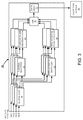
- FIG. 3 is a block diagram of an embodiment a single receiver within the plurality of networked receivers.
- FIG. 4 is a diagram of an embodiment of randomly positioned receiver antennae and the transmitter calibration template.
- FIG. 5 is a flow diagram of an embodiment of a process for calibrating the locations of receiver antennae in a receiver network.
- FIG. 6 is a diagram of an embodiment of a rigid receiver antennae arrangement.
- FIG. 7 is a diagram of another embodiment of arbitrarily positioned receiver antennae and a transmitter calibration template.
- RF communication systems and methods that can help quickly and accurately calculate and calibrate the relative positions of RF receivers, even if such RF receivers are randomly located within the tracking environment (e.g., a room, area, or region).
- Such RF communication systems include a receiver network of four or more receiver antennae that receive radio transmissions from one or more wireless mobile transmitters or transceivers (referred to as a tracked device) that transmit a radio-based signal to the receiver network; and a receiver station that computes the relative position of each tracked device using time difference of arrival of the signals of the tracked device received by each receiver antenna.
- the receiver station can compute the relative position of the individual receiver antenna through a self-calibration process that utilizes a template to guide the tracked device, in a three-dimensional environment, to predetermined reference points. As the tracked device moves to each known reference point on the template, the receiver station can use these points to calibrate the relative location of each receiver antenna by utilizing the time difference of arrival information of the received signals to develop a relative geometric layout of the receiver antennae in the receiver network.
- a tracked device transmits a signal that is received by at least four receiver antennae.
- the tracked device is placed on or in a unique calibration template.
- This template contains a number of known (by the receiver station) three-dimensional geometric reference points that the tracked device fits in or on and is moved through a predetermined sequence of locations.
- the multiple receiver antennae receive the signal of the tracked device and the receiver station, by using the known geometry of the reference points on the template and comparing that information with the time difference of arrival of the signal of the tracked device received at each receiver antenna, then computes the individual receiver antenna location.
- the tracked device has a button that sends a predetermined signal to the receiver station.
- the button is pressed to notify the receiver station to record that position point and reference it to the known position reference points known by the receiver station.
- the receiver station has calibrated the relative positions of the receiver antennae. After the positions of the receiver antennae have been calibrated, the receiver station can use the time difference of arrival of the radio signal to determine the three-dimensional position of the tracked device relative to the receiver network.
- FIG. 1 shows an embodiment of a wireless position tracking system 10 for tracking the position of an RF transmitter (i.e., tracked device) 12 .
- the tracked device 12 may be carried by, attached to, or embedded in an object whose position (x, y, z) is to be dynamically determined, and may be part of a transceiver or transducer. Examples of such objects include, but are not limited to, game controllers, TV remote control devices, mobile smart phones, laptop computers, and electronic tablets.
- the position tracking system 10 includes a receiver network 14 comprised of at least four RF receiver antennae 16 - 1 , 16 - 2 , 16 - 3 , and 16 - 4 (generally, 16 ), whose relative positions (X i , Y i , Z i ) are unknown (randomly placed), where i corresponds to the number of a particular antenna.
- Each receiver antenna 16 of the receiver network 16 is located near the RF transmitter 12 .
- At least four RF receiver antennae and one RF transmitter are required for determining the three-dimensional position of the tracked device 12 within the tracking environment.
- a calibration template with a known geometry and test point locations is used for the RF transmitter.
- the position tracking system 10 uses the predetermined, known positions to determine the relative positions of the receiver antenna in the receiver network 14 .
- the wireless position tracking system 10 further includes a receiver station 15 comprised of a controller unit 18 and a computing system 20 (optionally, with a display).
- the RF transmitter 12 associated with an object continuously transmits PN (pseudo noise) code modulated RF signals
- the receiver network 14 of receiver antennae 16 receives the modulated signals from RF transmitter 12 .
- the modulated signals are sent to the controller unit 18 over wires or cables 22 .
- the data obtained from controller unit 18 are sent to the computing system 20 , which comprises memory and a processor configured to calculate the transmitter antenna position (x, y, z), and then to represent the calculated position on the display screen or to provide the calculated position to other applications for further use.
- FIG. 2 shows an embodiment of an RF transmitter 12 , including an antenna 40 , a RF signal generator 42 , a modulator 44 , an amplifier 46 , and a reference oscillator (clock) 48 .
- the RF transmitter 12 which is associated with an object, also has a pseudo-noise (PN) code generator 50 that generates PN signals intrinsic to the object.
- PN pseudo-noise
- the reference oscillator 48 provides a stable reference oscillator signal for the PN code generator 50 and the RF signal generator 42 .
- the reference oscillator 48 uses a phase lock loop to generate the stable RF signal.
- the modulator 44 (e.g., a Bi-Phase Shift Key (BPSK) modulator) provides a modulated signal to be transmitted through the amplifier 46 and transmitter antenna 40 .
- the carrier frequency is 2.4 GHz and the PN code chip rate is 80 MHz.
- the carrier frequency can operate in any other frequency and the PN code chip rate can also be set at other rates.
- FIG. 3 shows an embodiment of the controller unit 18 , including de-spreader circuitry 60 , carrier frequency recovery circuitry 62 , spread signal recovery circuitry 64 , carrier frequency phase discriminator circuitry 66 , spread signal frequency phase comparison circuitry 68 , an analog-to-digital converter (ADC) circuit 70 , and data processing circuitry 72 .
- the de-spreader circuitry 60 includes a de-spreader circuit for each of the receiver antennae 16 . Each de-spreader circuit de-spreads the modulated signal received from its associated receiver antenna 16 . Each de-spreader circuit passes its de-spread signal to a carrier frequency recovery circuit 62 and to a spread signal (i.e., code) recovery circuit 64 . Each carrier frequency recovery circuitry 62 recovers the carrier signal and each spread signal frequency recovery circuitry 64 recovers the spread signal (a set of PN code correlative pulses) through a correlation process.
- ADC analog-to-digital converter
- the recovered carrier signal and spread signal are sent to the carrier frequency phase discriminator circuitry 66 and to the spread signal phase comparison circuitry (i.e., code discriminator) 68 , respectively, to compare the phase differences between the receiver antennae 16 .
- One of the receiver antennae 16 serves as a reference channel. In the embodiment shown, the receiver antenna 16 - 1 is chosen to be the reference channel.
- the carrier frequency discriminator circuits 66 determine the phase differences between the receiver antenna 16 - 2 and receiver antenna 16 - 1 , receiver antenna 16 - 3 and receiver antenna 16 - 1 , and receiver antenna 16 - 4 and receiver antenna 16 - 1 for the carrier signal; and the spread signal phase comparison circuitry 68 determines the phase differences between the receiver antenna 16 - 2 and receiver antenna 16 - 1 , receiver antenna 16 - 3 and receiver antenna 16 - 1 , and receiver antenna 16 - 4 and receiver antenna 16 - 1 for the spread signal.
- the spread signal phase compare circuitry 68 and carrier phase discriminator circuitry 66 provide the coarse and fine measurement of the time difference of arrival of the transmitted RF signal, respectively. Combining the coarse and fine time differences of arrival eliminates ambiguity and provides highly accurate position determination.
- the ADC 70 receives the carrier phase from the carrier phase discriminator circuitry 66 and the spread signal phase from the spread signal phase compare circuitry 68 and converts these phases into digital form.
- the data processor 72 receives the digitized phases and computes time difference of arrival using the difference in phase measurements (i.e., carrier phase minus spread signal phase) between each receiver antenna and the reference antenna (e.g., 16 - 1 ), and sends the time difference of arrival measurements to the computing system 20 .
- FIG. 4 shows an example of randomly mounted receiver antennae 16 and a calibration apparatus 80 .
- the receiver antenna 16 - 1 is positioned at (x 1 , y 1 , z 1 )
- the receiver antenna 16 - 2 is at (x 2 , y 2 , z 2 )
- the receiver antenna 16 - 3 is at (x 3 , y 3 , z 3 )
- the receiver antenna 16 - 4 is at (x 4 , y 4 , z 4 ), all of which are random locations (i.e., initially unknown) with respect to the calibration apparatus 80 .
- the calibration apparatus 80 can be one or more devices, machines separate from or part of the receiver station 15 , examples of which include, but are not limited to, a television and computer monitor.
- the calibration apparatus 80 provides a calibration template, defined as a plurality of geometric reference points on or in the calibration apparatus 80 known to the receiver station 15 .
- a calibration template defined as a plurality of geometric reference points on or in the calibration apparatus 80 known to the receiver station 15 .
- each of the corners of a computer monitor can be adapted to be part of a calibration template, used to calibrate the position tracking system for certain functions as such functions relate to the dimensions of this calibration apparatus.
- the corners of the display screen can be calibrated to record the shooting range.
- the tracked device 12 is placed, in succession, at each of these reference points, either on, in, or against the calibration apparatus.
- Each of the receiver antennae 16 receives the RF signals transmitted by the tracked device. Time difference of arrival measurements between receiver antennae 16 are used to calculate the relative positions of each receiver antenna 16 in the receiver network 14 .
- the calibration template includes four predetermined locations, referred to as reference points P 0 , P 1 , P 2 , and P 3 .
- P 0 is placed located at the origin (0, 0, 0)
- the other positions P 1 , P 2 and P 3 of the calibration template are located at (0, y 0 , 0), (x 0 , y 0 , z 0 ), and (x 0 , 0, z 0 ), respectively.
- Each of these reference points is known to the receiver station 15 , being stored in the memory of the receiver station. More than four points can be used as reference points, for example, at the middle of each edge of the calibration apparatus 80 .
- At each calibration reference point P there are three equations, so at least 4 calibration reference points are needed.
- the computing system 20 using the following simultaneous equations to compute locations of the receiver antennae 16 , where f 1 through f 12 are the distance differences of antennae locations in relation to the calibration reference points P 0 -P 3 .
- f 1 , f 4 , f 7 , and f 10 are the distance differences between receiver antennae 16 - 1 and 16 - 2 for reference points P 0 , P 1 , P 2 , and P 3 , respectively;
- f 2 , f 5 , f 8 , and f 11 are the distance difference measurements between receiver antennae 16 - 1 and 16 - 3 , and f 3 , f 6 , f 9 , and f 12 are the distance difference measurements between receiver antennae 16 - 1 and 16 - 4 .
- f 1 ⁇ square root over ( x 2 2 +y 2 2 +z 2 2 ) ⁇ square root over ( x 1 2 +y 1 2 +z 1 2 ) ⁇ (Eq. 1)
- f 2 ⁇ square root over ( x 3 2 +y 3 2 +z 3 2 ) ⁇ square root over ( x 1 2 +y 1 2 +z 1 2 ) ⁇
- f 3 ⁇ square root over ( x 4 2 +y 4 2 +z 4 2 ) ⁇ square root over ( x 1 2 +y 1 2 +z 1 2 ) ⁇ (Eq. 3)
- f 4 ⁇ square root over ( x 2 2 +( y 2 ⁇ y 0 ) 2 +z 2 2 ) ⁇ square root over ( x 1 2 +( y 1 ⁇ y 0 ) 2 +z 1 2 ) ⁇ (Eq. 4)
- f 5 ⁇ square root over ( x 3 2 +( y 3 ⁇ y 0 ) 2 +z 3 2 ) ⁇ square root over ( x 1 2 +( y 1 ⁇ y 0 ) 2 +z 1 2 ) ⁇ (Eq. 4)
- f 7 ⁇ square root over (( x 2 +x 0 ) 2 +( y 2 ⁇ y 0 ) 2 +( z 2 ⁇ z 0 ) 2 ) ⁇ square root over (( x 1 +x 0 ) 2 +( y 1 ⁇ y 0 ) 2 +( z 1 ⁇ z 0 ) 2 ) ⁇ (Eq.
- f 8 ⁇ square root over (( x 3 +x 0 ) 2 +( y 3 ⁇ y 0 ) 2 +( z 3 ⁇ z 0 ) 2 ) ⁇ square root over (( x 1 +x 0 ) 2 +( y 1 ⁇ y 0 ) 2 +( z 1 ⁇ z 0 ) 2 ) ⁇ (Eq.
- f 10 ⁇ square root over (( x 2 +x 0 ) 2 +y 2 2 +( z 2 ⁇ z 0 ) 2 ) ⁇ square root over (( x 1 +x 0 ) 2 +y 1 2 +( z 1 ⁇ z 0 ) 2 ) ⁇ (Eq. 10)
- f 11 ⁇ square root over (( x 3 +x 0 ) 2 +y 3 2 +( z 3 ⁇ z 0 ) 2 ) ⁇ square root over (( x 1 +x 0 ) 2 +y 1 2 +( z 1 ⁇ z 0 ) 2 ) ⁇ (Eq.
- f 12 ⁇ square root over (( x 4 +x 0 ) 2 +y 4 2 +( z 4 ⁇ z 0 ) 2 ) ⁇ square root over (( x 1 +x 0 ) 2 +y 1 2 +( z 1 ⁇ z 0 ) 2 ) ⁇ (Eq. 12)
- One embodiment uses the Levenberg-Marquardt (LM) algorithm to compute positioning, which is an iterative technique that locates the minimum of a multivariate function that is expressed as the sum of squares of non-linear real-valued functions. It is a standard technique for non-linear least-squares problems.
- the LM algorithm can be considered a combination of steepest descent and the Gauss-Newton method.
- the LM algorithm receives, as input, a vector function f, a measurement vector x, and initial parameters estimate p 0 , and produces, as output, a vector p minimizing sum of (x ⁇ f(p)) ⁇ circumflex over ( ) ⁇ 2.
- the positions of the receiver antennae 16 are provided.
- the computing system 20 computes the position (x, y, z) of the tracked device 12 by using equations with the calibrated known relative three-dimensional positions of the receiver antennae 16 . To solve these equations, the computing system 20 uses the time difference of arrival information received from the controller unit 18 .
- f 1 ⁇ square root over (( x 2 ⁇ x ) 2 +( y 2 ⁇ y ) 2 +( z 2 ⁇ z ) 2 ) ⁇ square root over (( x 1 ⁇ x ) 2 +( y 1 ⁇ y ) 2 +( z 1 ⁇ z ) 2 ) ⁇ (Eq.
- f 2 ⁇ square root over (( x 3 ⁇ x ) 2 +( y 3 ⁇ y ) 2 +( z 3 ⁇ z ) 2 ) ⁇ square root over (( x 1 ⁇ x ) 2 +( y 1 ⁇ y ) 2 +( z 1 ⁇ z ) 2 ) ⁇
- f 3 ⁇ square root over (( x 4 ⁇ x ) 2 +( y 4 ⁇ y ) 2 +( z 4 ⁇ z ) 2 ) ⁇ square root over (( x 1 ⁇ x ) 2 +( y 1 ⁇ y ) 2 +( z 1 ⁇ z ) 2 ) ⁇ (Eq.
- FIG. 5 shows an embodiment of a process 120 for calibrating the locations of the receiver antennae 16 .
- the tracked device 12 is placed at one of the reference points P of the calibration apparatus 80 ( FIG. 4 ).
- the tracked device 12 is activated (step 124 ), for example, by the press of a button on the device, to transmit an RF signal.
- Each of the receiver antennae 16 receive (step 126 ) the RF signal, which pass to the controller unit 18 .
- the controller unit 18 computes time difference of arrival for the RF signal between a chosen reference receiver antenna and each of the other receiver antennae. In one embodiment, the controller unit 18 computes (step 128 ) the time difference of arrival for the carrier signal and the spread signal obtained from the RF signal, as described in connection with FIG. 3 . The controller unit 18 sends (step 130 ) this set of time difference of arrival measurements to the computing system 20 . The computing system 20 associates (step 132 ) this set of time difference of arrival measurements with the particular known reference point from which the RF signal originated. In one embodiment, the computing system 20 is configured to associate received sets of time difference of arrival measurements with known reference points according to a predefined sequence. For example, the first set of received time difference of arrival measurements is associated with reference point P 0 , the second received set with reference point P 1 , and so on.
- a calibration application executing on the tracked device 12 can guide the user to move the tracked device 12 from one reference point on the calibration apparatus 80 to the next. Alternatively, the calibration apparatus 80 itself can signal to the user where to next place the tracked device 12 .
- the computing system 20 computes (step 136 ) the relative locations of each receiver antenna 16 based on the sets of time difference of arrival measurements and on the known locations of the used reference points, as described in connection with FIG. 4 .
- FIG. 6 shows an example embodiment having rigidly mounted receiver antennae 16 .
- the receiver antenna 16 - 1 as a reference point, is chosen to be at the origin of the coordinate system.
- the physical spacing information between the receiver antennae is known; namely, the coordinates of receiver antenna 16 - 2 , receiver antenna 16 - 3 , and receiver antenna 16 - 4 are known relative to the reference point (i.e., receiver antenna 16 - 1 ). Accordingly, calibration is not required because the positions of the receiver antennae are known.
- one of the receiver antennae (e.g., 16 - 1 ) coordinates is taken to be the reference point at origin (0, 0, 0) and the positions of the other receiver antenna 16 - 2 , 16 - 3 , and 16 - 4 are considered to be at (x 2 , y 2 , z 2 ), (x 3 , y 3 , z 3 ), and (x 4 , y 4 , z 4 ), respectively.
- the position of the RF transmitter 12 (or tracked device) can then be tracked.
- f 1 ⁇ square root over (( x 2 ⁇ x ) 2 +( y 2 ⁇ y ) 2 +( z 2 ⁇ z ) 2 ) ⁇ square root over ( x 2 +y 2 +z 2 ) ⁇
- f 2 ⁇ square root over (( x 3 ⁇ x ) 2 +( y 3 ⁇ y ) 2 +( z 3 ⁇ z ) 2 ) ⁇ square root over ( x 2 +y 2 +z 2 ) ⁇ (Eq.
- f 3 ⁇ square root over (( x 4 ⁇ x ) 2 +( y 4 ⁇ y ) 2 +( z 4 ⁇ z ) 2 ) ⁇ square root over ( x 2 +y 2 +z 2 ) ⁇ (Eq. 18) where x, y, z are the coordinates of the RF transmitter 3D position relative to the origin receiver antenna 16 - 1 at (0, 0, 0).
- the RF-transmitting device 12 when the RF-transmitting device 12 is placed at one of the reference points P and activated to transmit an RF signal, for example, by the press of a button, the device transmits an ultra-wideband (UWB) signal.
- the UWB signal carries a timestamp corresponding to when the device 12 transmitted the RF signal.
- the four receivers (herein, used interchangeably with receiver antennae 16 ) are synchronized, operating from the same clock (i.e., crystal oscillator). Each of the receiver antennae 16 receive the UWB signal. Each receiver antenna generates a timestamp when that receiver antenna received the UWB signal from the RF-transmitting device.
- TOA time of arrival
- the time difference measurement can be inaccurate, making individual range measurements unreliable, although the receivers are synchronized.
- TDOA time difference of arrival
- ⁇ t 20 ( t r2 ⁇ t r0 ) ⁇ ( ⁇ t r2 ⁇ t r0 ) (Eq. 23)
- ⁇ t 30 ( t r3 ⁇ t r0 ) ⁇ ( ⁇ t r3 ⁇ t r0 ) (Eq. 24)
- ⁇ t ri ( t r1 ⁇ t r0 ) (Eq. 25)
- ⁇ t 20 ( t r2 ⁇ t r0 ) (Eq. 26)
- ⁇ t 30 ( t r3 ⁇ t r0 ) (Eq. 27)
- Equations 25, 26 and 27 show that the effect of jitter or draft error has been removed from the calculations, and thus these time difference of arrival measurements can be used to perform automatic setup calibration.
- the distance equations for computing the relative position of the receiver antennae are the same as those described previously in connection with time difference of arrival measurements, namely equations 1-12.
- FIG. 7 shows an embodiment of three randomly positioned receiver antennae 16 - 1 , 16 - 2 , and 16 - 3 , and a calibration apparatus 80 ′ having a calibration template comprised of three reference points P 1 , P 2 , and P 3 .
- a calibration apparatus 80 ′ having a calibration template comprised of three reference points P 1 , P 2 , and P 3 .
- three antennae and three reference points are shown, the principles described herein apply to embodiments with more than three reference points and more than three receiver antennae.
- FIG. 7 shows an embodiment of three randomly positioned receiver antennae 16 - 1 , 16 - 2 , and 16 - 3 , and a calibration apparatus 80 ′ having a calibration template comprised of three reference points P 1 , P 2 , and P 3 .
- the receiver antenna 16 - 1 is positioned at (x 1 , y 1 , z 1 ), the receiver antenna 16 - 2 is at (x 2 , y 2 , z 2 ), and the receiver antenna 16 - 3 is at (x 3 , y 3 , z 3 ), all of which are at random or arbitrary locations (i.e., initially unknown) with respect to the calibration apparatus 80 ′.
- the calibration apparatus 80 ′ can be one or more devices, machines separate from or part of the receiver station 15 ( FIG. 1 ), examples of which include, but are not limited to, a television and computer monitor.
- the calibration apparatus 80 ′ provides a calibration template, defined as the three geometric reference points P 1 , P 2 , and P 3 disposed on or in the calibration apparatus 80 ′ known to the receiver station 15 .
- each of the corners of a computer monitor can be adapted to be part of calibration template, used to calibrate the position tracking system for certain functions, as such functions relate to the dimensions of this calibration apparatus.
- the tracked device 12 i.e., RF-transmitting device of FIG. 1
- the tracked device transmits an ultra-wideband (UWB) signal, which carries a timestamp corresponding to when the tracked device 12 transmitted the RF signal.
- UWB ultra-wideband
- Each of the receiver antennae 16 receives the UWB signals transmitted by the tracked device.
- Time of arrival (TOA) measurements are used to calculate the relative positions of each receiver antenna 16 in the receiver network 14 ( FIG. 1 , minus the fourth antenna 16 - 4 ). These TOA measurements can be based on one-way communications from the tracked device 12 to each of the receivers 16 or on two-way handshake between the tracked device 12 and each receiver 16 .
- the tracked device 12 is configured with an RF receiver (not shown) to receive UWB signals back from the receivers 16 .
- This RF receiver can be part of an RF transceiver that provides the RF transmitter of the RF-transmitting device.
- a processor (not shown) of the RF-transmitting device Based on round-trip times determined from the timestamps included in the UWB signals (by the tracked device and by the receivers), a processor (not shown) of the RF-transmitting device computes the distance (i.e., range) to each receiver antenna, and can then use the three computed ranges to the receivers to triangulate its own (x, y, z) position in relation to the receivers.
- the RF-transmitting device 12 performs this computation at each of the three reference points where the tracked device is placed in succession.
- the RF-transmitting device 12 transmits these computed ranges to the controller unit 18 ( FIG. 1 ), for forwarding to the computing system 20 , which computes the relative positions of the receiver antennae based on these ranges.
- the tracked device 12 can transmit the timestamps back to the controller unit 18 so the computing system 20 can perform the range calculations and then the relative positions of the receiver antennae based on these ranges.
- the calibration template 80 ′ includes three predetermined locations, referred to previously as the reference points P 1 , P 2 , and P 3 .
- P 1 is placed located at the origin (0, 0, 0)
- the other two positions P 2 , and P 3 of the calibration template are located at (0, y 0 , z 0 ), and ( ⁇ x 0 , 0, z 0 ), respectively.
- Each of these reference points P 1 , P 2 , and P 3 is known relative to each other by the receiver station 15 , being stored in the memory of the receiver station. More than three points can be used as reference points, for example, at the middle of each edge of the calibration apparatus 80 ′.
- the computing system 20 uses the following simultaneous equations to compute locations of the receiver antennae, where d 11 , d 12 . . . through d 33 are the distances of the antennae locations in relation to the calibration reference points P 1 , P 2 , and P 3 .
- d 11 is the distance of the reference point P 1 from the receiver antennae 16 - 1
- d 12 is the distance of the reference point P 1 from the receiver antennae 16 - 2
- d 13 is the distance of the reference point P 1 from the receiver antennae 16 - 3
- d 21 is the distance of the reference point P 2 from the receiver antennae 16 - 1
- d 31 is the distance of the reference point P 3 from the receiver antennae 16 - 1 .
- d 11 ⁇ square root over ( x 1 2 +y 1 2 +z 1 2 ) ⁇ (Eq. 28)
- d 12 ⁇ square root over ( x 2 2 +y 2 2 +z 2 2 ) ⁇ (Eq. 29)
- d 13 ⁇ square root over ( x 3 2 +y 3 2 +z 3 2 ) ⁇ (Eq. 30)
- d 21 ⁇ square root over ( x 1 2 +( y 1 ⁇ y 0 ) 2 +( z 1 ⁇ z 0 ) 2 ) ⁇ (Eq. 31)
- d 22 ⁇ square root over ( x 2 2 +( y 2 ⁇ y 0 ) 2 +( z 2 ⁇ z 0 ) 2 ) ⁇ (Eq. 32)
- d 23 ⁇ square root over ( x 3 2 +( y 3 ⁇ y 0 ) 2 +( z 3 ⁇ z 0 ) 2 ) ⁇ (Eq. 33)
- d 31 ⁇ square root over (( x 1 +x 0 ) 2 +y 1 2 +( z 1 ⁇ z 0 ) 2 ) ⁇ (Eq. 34)
- d 32 ⁇ square root over (( x 2 ⁇ x 0 ) 2 +y 0 2 +( z 2 ⁇ z 0 ) 2 ) ⁇ (Eq. 35)
- d 33 ⁇ square root over (( x 3 +x 0 ) 2 +y 3 2 +( z 3 ⁇ z 0 ) 2 ) ⁇ (Eq. 36)
- One embodiment uses the Levenberg-Marquardt (LM) algorithm to solve the nine equations numbered 28-36 to produce the relative locations of the receiver antennae in three-dimensional coordinates.
- LM Levenberg-Marquardt
- the reference points not all be on a plane that mirrors (i.e., is parallel) the plane of the receiver antennae (if the receiver antennae are co-planar).
- the reference points cannot all have a common value for that same axis. For example, if the z-axis value for all reference antennae is equal to 10, then the reference points cannot all have a common z-axis value (e.g., their z-axis values cannot all be equal to 8, or all equal to 14, or to 6).
- At least one of the z-axis values of the reference points must be different from the z-axis values of the other reference points. If the three receiver antennae are non-coplanar (in this context meaning not all antennae have the same value for one of its x, y, or z axes), for example, because of arbitrary placement, the reference points can be coplanar or non-coplanar.
- aspects of the present invention may be embodied as a system, method, and computer program product.
- aspects of the present invention may be embodied entirely in hardware, entirely in software (including, but not limited to, firmware, program code, resident software, microcode), or in a combination of hardware and software. All such embodiments may generally be referred to herein as a circuit, a module, or a system.
- aspects of the present invention may be in the form of a computer program product embodied in one or more computer readable media having computer readable program code embodied thereon.
- the computer readable medium may be a computer readable signal medium or a computer readable storage medium.
- the computer readable medium may be a non-transitory computer readable storage medium, examples of which include, but are not limited to, an electronic, magnetic, optical, electromagnetic, infrared, or semiconductor system, apparatus, or device, or any suitable combination thereof.
- a computer readable storage medium may be any tangible medium that can contain or store a program for use by or in connection with an instruction execution system, apparatus, device, computer, computing system, computer system, or any programmable machine or device that inputs, processes, and outputs instructions, commands, or data.
- a non-exhaustive list of specific examples of a computer readable storage medium include an electrical connection having one or more wires, a portable computer diskette, a floppy disk, a hard disk, a random access memory (RAM), a read-only memory (ROM), a USB flash drive, an non-volatile RAM (NVRAM or NOVRAM), an erasable programmable read-only memory (EPROM or Flash memory), a flash memory card, an electrically erasable programmable read-only memory (EEPROM), an optical fiber, a portable compact disc read-only memory (CD-ROM), a DVD-ROM, an optical storage device, a magnetic storage device, or any suitable combination thereof.
- RAM random access memory
- ROM read-only memory
- NVRAM non-volatile RAM
- EPROM or Flash memory erasable programmable read-only memory
- EEPROM electrically erasable programmable read-only memory
- an optical fiber a portable compact disc read-only memory (CD-ROM), a DVD-
- a computer readable signal medium may include a propagated data signal with computer readable program code embodied therein, for example, in baseband or as part of a carrier wave. Such a propagated signal may take any of a variety of forms, including, but not limited to, electro-magnetic, optical, or any suitable combination thereof.
- a computer readable signal medium may be any computer readable medium that is not a computer readable storage medium and that can communicate, propagate, or transport a program for use by or in connection with an instruction execution system, apparatus, or device. As used herein, a computer readable storage medium is not a computer readable propagating signal medium or a propagated signal.
- Program code may be embodied as computer-readable instructions stored on or in a computer readable storage medium as, for example, source code, object code, interpretive code, executable code, or combinations thereof. Any standard or proprietary, programming or interpretive language can be used to produce the computer-executable instructions. Examples of such languages include C, C++, Pascal, JAVA, BASIC, Smalltalk, Visual Basic, and Visual C++.
- Transmission of program code embodied on a computer readable medium can occur using any appropriate medium including, but not limited to, wireless, wired, optical fiber cable, radio frequency (RF), or any suitable combination thereof.
- RF radio frequency
- the program code may execute entirely on a user's device, partly on the user's device, as a stand-alone software package, partly on the user's device and partly on a remote computer or entirely on a remote computer or server.
- Any such remote computer may be connected to the user's device through any type of network, including a local area network (LAN) or a wide area network (WAN), or the connection may be made to an external computer (for example, through the Internet using an Internet Service Provider).
- LAN local area network
- WAN wide area network
- Internet Service Provider for example, AT&T, MCI, Sprint, EarthLink, MSN, GTE, etc.
- the methods of this invention can be implemented on a special purpose computer, a programmed microprocessor or microcontroller and peripheral integrated circuit element(s), an ASIC or other integrated circuit, a digital signal processor, a hard-wired electronic or logic circuit such as discrete element circuit, a programmable logic device such as PLD, PLA, FPGA, PAL, or the like.
- any device capable of implementing a state machine that is in turn capable of implementing the proposed methods herein can be used to implement the principles of this invention.
- the disclosed methods may be readily implemented in software using object or object-oriented software development environments that provide portable source code that can be used on a variety of computer or workstation platforms.
- the disclosed system may be implemented partially or fully in hardware using standard logic circuits or a VLSI design. Whether software or hardware is used to implement the systems in accordance with this invention is dependent on the speed and/or efficiency requirements of the system, the particular function, and the particular software or hardware systems or microprocessor or microcomputer systems being utilized.
- the methods illustrated herein can be readily implemented in hardware and/or software using any known or later developed systems or structures, devices and/or software by those of ordinary skill in the applicable art from the functional description provided herein and with a general basic knowledge of the computer and image processing arts.
- the disclosed methods may be readily implemented in software executed on programmed general-purpose computer, a special purpose computer, a microprocessor, or the like.
- the systems and methods of this invention may be implemented as program embedded on personal computer such as JAVA® or CGI script, as a resource residing on a server or graphics workstation, as a plug-in, or the like.
- the system may also be implemented by physically incorporating the system and method into a software and/or hardware system.
Landscapes
- Engineering & Computer Science (AREA)
- Physics & Mathematics (AREA)
- General Physics & Mathematics (AREA)
- Radar, Positioning & Navigation (AREA)
- Remote Sensing (AREA)
- Computer Networks & Wireless Communication (AREA)
- Signal Processing (AREA)
- Position Fixing By Use Of Radio Waves (AREA)
Abstract
Description
f 1=√{square root over (x 2 2 +y 2 2 +z 2 2)}−√{square root over (x 1 2 +y 1 2 +z 1 2)} (Eq. 1)
f 2=√{square root over (x 3 2 +y 3 2 +z 3 2)}−√{square root over (x 1 2 +y 1 2 +z 1 2)} (Eq. 2)
f 3=√{square root over (x 4 2 +y 4 2 +z 4 2)}−√{square root over (x 1 2 +y 1 2 +z 1 2)} (Eq. 3)
f 4=√{square root over (x 2 2+(y 2 −y 0)2 +z 2 2)}−√{square root over (x 1 2+(y 1 −y 0)2 +z 1 2)} (Eq. 4)
f 5=√{square root over (x 3 2+(y 3 −y 0)2 +z 3 2)}−√{square root over (x 1 2+(y 1 −y 0)2 +z 1 2)} (Eq. 5)
f 6=√{square root over (x 4 2+(y 4 −y 0)2 +z 4 2)}−√{square root over (x 1 2+(y 1 −y 0)2 +z 1 2)} (Eq. 6)
f 7=√{square root over ((x 2 +x 0)2+(y 2 −y 0)2+(z 2 −z 0)2)}−√{square root over ((x 1 +x 0)2+(y 1 −y 0)2+(z 1 −z 0)2)} (Eq. 7)
f 8=√{square root over ((x 3 +x 0)2+(y 3 −y 0)2+(z 3 −z 0)2)}−√{square root over ((x 1 +x 0)2+(y 1 −y 0)2+(z 1 −z 0)2)} (Eq. 8)
f 9=√{square root over ((x 4 +x 0)2+(y 4 −y 0)2+(z 4 −z 0)2)}−√{square root over ((x 1 +x 0)2+(y 1 −y 0)2+(z 1 −z 0)2)} (Eq. 9)
f 10=√{square root over ((x 2 +x 0)2 +y 2 2+(z 2 −z 0)2)}−√{square root over ((x 1 +x 0)2 +y 1 2+(z 1 −z 0)2)} (Eq. 10)
f 11=√{square root over ((x 3 +x 0)2 +y 3 2+(z 3 −z 0)2)}−√{square root over ((x 1 +x 0)2 +y 1 2+(z 1 −z 0)2)} (Eq. 11)
f 12=√{square root over ((x 4 +x 0)2 +y 4 2+(z 4 −z 0)2)}−√{square root over ((x 1 +x 0)2 +y 1 2+(z 1 −z 0)2)} (Eq. 12)
f 1=√{square root over ((x 2 −x)2+(y 2 −y)2+(z 2 −z)2)}−√{square root over ((x 1 −x)2+(y 1 −y)2+(z 1 −z)2)} (Eq. 13)
f 2=√{square root over ((x 3 −x)2+(y 3 −y)2+(z 3 −z)2)}−√{square root over ((x 1 −x)2+(y 1 −y)2+(z 1 −z)2)} (Eq. 14)
f 3=√{square root over ((x 4 −x)2+(y 4 −y)2+(z 4 −z)2)}−√{square root over ((x 1 −x)2+(y 1 −y)2+(z 1 −z)2)} (Eq. 15)
where (xi, yi, zi, i=1, 2, 3, 4) are the solution from the calibration procedure (i.e., the now known positions of the receiver antennae 16), and (x, y, z) is the position of the
f 1=√{square root over ((x 2 −x)2+(y 2 −y)2+(z 2 −z)2)}−√{square root over (x 2 +y 2 +z 2)} (Eq. 16)
f 2=√{square root over ((x 3 −x)2+(y 3 −y)2+(z 3 −z)2)}−√{square root over (x 2 +y 2 +z 2)} (Eq. 17)
f 3=√{square root over ((x 4 −x)2+(y 4 −y)2+(z 4 −z)2)}−√{square root over (x 2 +y 2 +z 2)} (Eq. 18)
where x, y, z are the coordinates of the RF transmitter 3D position relative to the origin receiver antenna 16-1 at (0, 0, 0).
t=(t r +Δt r)−(t t +Δt t), (Eq. 19)
where tr is the timestamp of a receiver, Δtr is the receiver jitter or draft error, and tt is the timestamp of the RF-transmitting device, Δtt is the RF transmitter jitter or draft error.
t j=(t rj +Δt rj)−(t t +Δt t), (Eq. 20)
where the index value, j, identifies the given receiver antenna, and j∈(0,3).
Δt 10 =t 1 −t 0=((t r1 −Δt r1)−(t t −Δt t))−((t r0 −Δt r0)−(t t −Δt t)) (Eq. 21)
which reduces to: Δt 10=(t r1 −t r0)−(Δt r1 −Δt r0) (Eq. 22)
Δt 20=(t r2 −t r0)−(Δt r2 −Δt r0) (Eq. 23)
Δt 30=(t r3 −t r0)−(Δt r3 −Δt r0) (Eq. 24)
Δt 10=(t r1 −t r0) (Eq. 25)
Δt 20=(t r2 −t r0) (Eq. 26)
Δt 30=(t r3 −t r0) (Eq. 27)
d 10 =Δt 10*c=√{square root over (x 2 2 +y 2 2 +z 2 2)}−√{square root over (x 1 2 +y 1 2 +z 1 2)}
d 20 =Δt 20 *c=√{square root over (x 3 2 +y 3 2 +z 3 2)}−√{square root over (x 1 2 +y 1 2 +z 1 2)}
d 30 =Δt 30 *x=√{square root over (x 4 2 +y 4 2 +z 4 2)}−√{square root over (x 1 2 +y 1 2 +z 1 2)}
d 11=√{square root over (x 1 2 +y 1 2 +z 1 2)} (Eq. 28)
d 12=√{square root over (x 2 2 +y 2 2 +z 2 2)} (Eq. 29)
d 13=√{square root over (x 3 2 +y 3 2 +z 3 2)} (Eq. 30)
d 21=√{square root over (x 1 2+(y 1 −y 0)2+(z 1 −z 0)2)} (Eq. 31)
d 22=√{square root over (x 2 2+(y 2 −y 0)2+(z 2 −z 0)2)} (Eq. 32)
d 23=√{square root over (x 3 2+(y 3 −y 0)2+(z 3 −z 0)2)} (Eq. 33)
d 31=√{square root over ((x 1 +x 0)2 +y 1 2+(z 1 −z 0)2)} (Eq. 34)
d 32=√{square root over ((x 2 −x 0)2 +y 0 2+(z 2 −z 0)2)} (Eq. 35)
d 33=√{square root over ((x 3 +x 0)2 +y 3 2+(z 3 −z 0)2)} (Eq. 36)
Claims (20)
Priority Applications (1)
| Application Number | Priority Date | Filing Date | Title |
|---|---|---|---|
| US16/356,285 US10856108B2 (en) | 2013-01-18 | 2019-03-18 | System and method of locating a radio frequency (RF) tracking device using a calibration routine |
Applications Claiming Priority (4)
| Application Number | Priority Date | Filing Date | Title |
|---|---|---|---|
| US201361754402P | 2013-01-18 | 2013-01-18 | |
| US14/158,896 US9482741B1 (en) | 2013-01-18 | 2014-01-20 | System and method of locating a radio frequency (RF) tracking device using a calibration routine |
| US15/246,783 US10237698B2 (en) | 2013-01-18 | 2016-08-25 | System and method of locating a radio frequency (RF) tracking device using a calibration routine |
| US16/356,285 US10856108B2 (en) | 2013-01-18 | 2019-03-18 | System and method of locating a radio frequency (RF) tracking device using a calibration routine |
Related Parent Applications (1)
| Application Number | Title | Priority Date | Filing Date |
|---|---|---|---|
| US15/246,783 Continuation-In-Part US10237698B2 (en) | 2013-01-18 | 2016-08-25 | System and method of locating a radio frequency (RF) tracking device using a calibration routine |
Publications (2)
| Publication Number | Publication Date |
|---|---|
| US20190215662A1 US20190215662A1 (en) | 2019-07-11 |
| US10856108B2 true US10856108B2 (en) | 2020-12-01 |
Family
ID=67140264
Family Applications (1)
| Application Number | Title | Priority Date | Filing Date |
|---|---|---|---|
| US16/356,285 Active 2034-04-08 US10856108B2 (en) | 2013-01-18 | 2019-03-18 | System and method of locating a radio frequency (RF) tracking device using a calibration routine |
Country Status (1)
| Country | Link |
|---|---|
| US (1) | US10856108B2 (en) |
Cited By (1)
| Publication number | Priority date | Publication date | Assignee | Title |
|---|---|---|---|---|
| US20240272292A1 (en) * | 2020-08-18 | 2024-08-15 | Zhejiang Geely Holding Group Co., Ltd | Vehicle-mounted positioning assembly, method, device, and apparatus employing ultra-wideband |
Families Citing this family (2)
| Publication number | Priority date | Publication date | Assignee | Title |
|---|---|---|---|---|
| US11127434B2 (en) * | 2019-12-19 | 2021-09-21 | Ari Krupnik | Timecode generator with global accuracy and flexible framerate |
| DE102020104658A1 (en) * | 2020-02-21 | 2021-08-26 | Vr Coaster Gmbh & Co. Kg | Method for providing a virtual reality experience for at least one passenger of a ride and ride |
Citations (179)
| Publication number | Priority date | Publication date | Assignee | Title |
|---|---|---|---|---|
| US2408122A (en) | 1940-11-15 | 1946-09-24 | Collins Radio Co | Heterodyne direction finder with single receiver |
| US3824596A (en) | 1972-09-27 | 1974-07-16 | Southwest Res Inst | Automatic sector indicating direction finder system |
| US3940700A (en) | 1972-08-15 | 1976-02-24 | Paul Haas | Method and installation for the detection of a source generating electro-magnetic oscillations |
| US4328499A (en) | 1979-10-24 | 1982-05-04 | The Marconi Company Limited | Radio direction finding systems |
| US5010343A (en) | 1988-04-26 | 1991-04-23 | Vaisala Oy | Method and device in the antenna and receiving system of a radio theodolite |
| US5343212A (en) | 1992-12-11 | 1994-08-30 | Litton Industries, Inc. | (AOA/LBI) emitter ranging method and apparatus |
| US5426438A (en) | 1992-12-30 | 1995-06-20 | Delfin Systems | Method and apparatus for adaptively determining the bearing angle of a radio frequency signal |
| US5510800A (en) | 1993-04-12 | 1996-04-23 | The Regents Of The University Of California | Time-of-flight radio location system |
| US5574468A (en) | 1995-04-20 | 1996-11-12 | Litton Systems, Inc. | Phase-equivalent interferometer arrays |
| US5592180A (en) | 1992-08-20 | 1997-01-07 | Nexus1994 Limited | Direction finding and mobile location system for trunked mobile radio systems |
| US5600330A (en) | 1994-07-12 | 1997-02-04 | Ascension Technology Corporation | Device for measuring position and orientation using non-dipole magnet IC fields |
| US5657026A (en) | 1996-01-26 | 1997-08-12 | Electronic Tracking Systems, Inc. | Beacon signal receiving system |
| US5923286A (en) | 1996-10-23 | 1999-07-13 | Honeywell Inc. | GPS/IRS global position determination method and apparatus with integrity loss provisions |
| US5953683A (en) | 1997-10-09 | 1999-09-14 | Ascension Technology Corporation | Sourceless orientation sensor |
| US6088653A (en) | 1996-12-31 | 2000-07-11 | Sheikh; Suneel I. | Attitude determination method and system |
| US6101178A (en) | 1997-07-10 | 2000-08-08 | Ksi Inc. | Pseudolite-augmented GPS for locating wireless telephones |
| US6167347A (en) | 1998-11-04 | 2000-12-26 | Lin; Ching-Fang | Vehicle positioning method and system thereof |
| WO2001006401A1 (en) | 1999-07-15 | 2001-01-25 | Pinpoint Corporation | Method and apparatus for mobile tag reading |
| US6255991B1 (en) | 2000-01-19 | 2001-07-03 | Trw Inc. | Low cost angle of arrival measurement system |
| US6259398B1 (en) * | 2000-05-19 | 2001-07-10 | Sri International | Multi-valued variable ambiguity resolution for satellite navigation signal carrier wave path length determination |
| US20020021277A1 (en) | 2000-04-17 | 2002-02-21 | Kramer James F. | Interface for controlling a graphical image |
| US6409687B1 (en) | 1998-04-17 | 2002-06-25 | Massachusetts Institute Of Technology | Motion tracking system |
| US6417802B1 (en) | 2000-04-26 | 2002-07-09 | Litton Systems, Inc. | Integrated inertial/GPS navigation system |
| US20020140745A1 (en) | 2001-01-24 | 2002-10-03 | Ellenby Thomas William | Pointing systems for addressing objects |
| US20020177476A1 (en) | 2001-05-22 | 2002-11-28 | Chou Y. Hong | Durable global asset-tracking device and a method of using the same |
| US6496778B1 (en) | 2000-09-14 | 2002-12-17 | American Gnc Corporation | Real-time integrated vehicle positioning method and system with differential GPS |
| US6512748B1 (en) | 1998-01-30 | 2003-01-28 | Ntt Mobile Communications Network Inc. | Radio paging signal coding control scheme using variable number of logical channels according to paging signal traffic |
| US20030053492A1 (en) | 2000-09-01 | 2003-03-20 | Osamu Matsunaga | Multiplexer, receiver, and multiplex transmission method |
| US20030120425A1 (en) | 2001-12-26 | 2003-06-26 | Kevin Stanley | Self-correcting wireless inertial navigation system and method |
| US6593885B2 (en) | 2000-04-27 | 2003-07-15 | Wherenet Corp | Low cost DTOA location processing system based on multiple readers-to-single processor architecture |
| US20030176196A1 (en) | 2002-03-18 | 2003-09-18 | Hall Christopher J. | Method and apparatus for geolocating a wireless communications device |
| US6630904B2 (en) | 1999-02-02 | 2003-10-07 | The Charles Stark Draper Laboratory, Inc. | Deeply-integrated adaptive INS/GPS navigator with extended-range code tracking |
| US20030195017A1 (en) | 1999-09-30 | 2003-10-16 | Tao Chen | Wireless communication system with base station beam sweeping |
| US6683568B1 (en) | 1999-05-14 | 2004-01-27 | Auckland Uniservices Limited | Position estimation services |
| US6697736B2 (en) | 2002-02-06 | 2004-02-24 | American Gnc Corporation | Positioning and navigation method and system thereof |
| US6721657B2 (en) | 2001-06-04 | 2004-04-13 | Novatel, Inc. | Inertial GPS navigation system |
| US6720920B2 (en) | 1997-10-22 | 2004-04-13 | Intelligent Technologies International Inc. | Method and arrangement for communicating between vehicles |
| US20040095907A1 (en) | 2000-06-13 | 2004-05-20 | Agee Brian G. | Method and apparatus for optimization of wireless multipoint electromagnetic communication networks |
| US6744436B1 (en) | 1999-05-25 | 2004-06-01 | Anthony Chirieleison, Jr. | Virtual reality warehouse management system complement |
| US20040107072A1 (en) | 2002-12-03 | 2004-06-03 | Arne Dietrich | Ins-based user orientation and navigation |
| US6750816B1 (en) | 2003-02-12 | 2004-06-15 | Novatel, Inc. | Integrated GPS-inertial system |
| US20040176102A1 (en) | 2001-11-20 | 2004-09-09 | Integrinautics Corporation | Multiple antenna multi-frequency measurement system |
| US20040203846A1 (en) | 2002-03-26 | 2004-10-14 | Germano Caronni | Apparatus and method for the use of position information in wireless applications |
| US20050001712A1 (en) | 2003-07-03 | 2005-01-06 | Yarbrough Craig D. | RF ID tag |
| WO2005010550A1 (en) | 2003-07-12 | 2005-02-03 | Qinetiq Limited | Direction finding |
| US6861982B2 (en) | 2001-08-16 | 2005-03-01 | Itt Manufacturing Enterprises, Inc. | System for determining position of an emitter |
| US6867774B1 (en) | 2002-12-02 | 2005-03-15 | Ngrain (Canada) Corporation | Method and apparatus for transforming polygon data to voxel data for general purpose applications |
| US20050057647A1 (en) | 2003-09-15 | 2005-03-17 | Nowak Michael P. | Method and system for calibrating a sensor |
| US20050143916A1 (en) | 2003-12-26 | 2005-06-30 | In-Jun Kim | Positioning apparatus and method combining RFID, GPS and INS |
| US20050275626A1 (en) | 2000-06-21 | 2005-12-15 | Color Kinetics Incorporated | Entertainment lighting system |
| US20060013070A1 (en) | 2002-12-04 | 2006-01-19 | Sverre Holm | Ultrasonic tracking and locating system |
| US6989789B2 (en) | 2000-02-25 | 2006-01-24 | Thales | Method for locating radioelectric sources using two-channel high resolution radiogoniometer |
| US20060022800A1 (en) | 2004-07-30 | 2006-02-02 | Reva Systems Corporation | Scheduling in an RFID system having a coordinated RFID tag reader array |
| US7009561B2 (en) | 2003-03-11 | 2006-03-07 | Menache, Llp | Radio frequency motion tracking system and method |
| US20060061469A1 (en) | 2004-09-21 | 2006-03-23 | Skyfence Inc. | Positioning system that uses signals from a point source |
| US20060066485A1 (en) | 2004-09-24 | 2006-03-30 | Guohua Min | Wireless tracking system based upon phase differences |
| US20060101497A1 (en) | 2004-06-25 | 2006-05-11 | International Business Machines Corporation | User-aware video display |
| US20060122495A1 (en) * | 2002-11-14 | 2006-06-08 | Kienzle Thomas C Iii | Interchangeable localizing devices for use with tracking systems |
| US20060192709A1 (en) | 2002-08-19 | 2006-08-31 | Q-Track, Inc. | Low frequency asset tag tracking system and method |
| US7143004B2 (en) | 1998-12-09 | 2006-11-28 | Microstrain, Inc. | Solid state orientation sensor with 360 degree measurement capability |
| US20060279459A1 (en) | 2005-06-10 | 2006-12-14 | Fujitsu Limited | Calibration apparatus and method for array antenna |
| US20060290508A1 (en) | 2005-06-23 | 2006-12-28 | Samsung Electronics Co., Ltd. | Reader, tags, radio frequency identification (RFID) system, and method thereof |
| US7168618B2 (en) | 2004-08-12 | 2007-01-30 | International Business Machines Corporation | Retail store method and system |
| US7190309B2 (en) | 2004-09-24 | 2007-03-13 | Hill Edward L | Radio signal transmitter with multiple antennas for improved position detection |
| US20070060384A1 (en) | 2005-09-14 | 2007-03-15 | Nintendo Co., Ltd. | Storage medium storing video game program |
| US7193559B2 (en) | 2003-01-21 | 2007-03-20 | Novatel, Inc. | Inertial GPS navigation system with modified kalman filter |
| US20070138270A1 (en) | 2005-12-20 | 2007-06-21 | United States Postal Service | Method and system for interrogating and processing codes |
| US7236091B2 (en) | 2005-02-10 | 2007-06-26 | Pinc Solutions | Position-tracking system |
| US20070205867A1 (en) | 2001-03-20 | 2007-09-06 | Lightwaves Systems, Inc. | Ultra wideband radio frequency identification system, method, and apparatus |
| US20070210920A1 (en) | 2006-03-09 | 2007-09-13 | George Panotopoulos | Identification (ID) system and method of operation thereof |
| US20070222560A1 (en) | 2006-03-23 | 2007-09-27 | Joshua Posamentier | Parallel RFID system using CDMA |
| US7292189B2 (en) | 2004-09-10 | 2007-11-06 | Worcester Polytechnic Institute | Methods and apparatus for high resolution positioning |
| US7295925B2 (en) | 1997-10-22 | 2007-11-13 | Intelligent Technologies International, Inc. | Accident avoidance systems and methods |
| US7315281B2 (en) | 2004-07-30 | 2008-01-01 | G2 Microsystems Pty. Ltd. | Location determination method and system for asset tracking devices |
| US20080007398A1 (en) | 2006-07-05 | 2008-01-10 | General Electric Company | System and method for tracking assets |
| US7336078B1 (en) | 2003-10-04 | 2008-02-26 | Seektech, Inc. | Multi-sensor mapping omnidirectional sonde and line locators |
| US20080048913A1 (en) | 2004-12-02 | 2008-02-28 | Commissariat A L'energie Atomique | Local Positioning System and Method |
| US20080143482A1 (en) | 2006-12-18 | 2008-06-19 | Radiofy Llc, A California Limited Liability Company | RFID location systems and methods |
| US20080154691A1 (en) | 2006-12-13 | 2008-06-26 | Wellman Timothy A | Fleet management system |
| US20080150678A1 (en) | 2006-11-13 | 2008-06-26 | Giobbi John J | Configuration of Interfaces for a Location Detection System and Application |
| US20080174485A1 (en) | 2007-01-24 | 2008-07-24 | Carani Sherry L | Tracking System and Method with Asset Tool Bar for Polling, Message, Historic Report, Location, Map and Geo Fence Features |
| US7409290B2 (en) | 2004-04-17 | 2008-08-05 | American Gnc Corporation | Positioning and navigation method and system thereof |
| US20080204322A1 (en) | 2003-11-03 | 2008-08-28 | Gordon Kenneth Andrew Oswald | Determining Positional Information |
| US7443342B2 (en) | 2004-01-13 | 2008-10-28 | The Nippon Signal Co., Ltd. | Reception time determining apparatus and distance measuring apparatus using the same |
| US20080266253A1 (en) | 2007-04-25 | 2008-10-30 | Lisa Seeman | System and method for tracking a laser spot on a projected computer screen image |
| US20080281618A1 (en) | 2007-05-09 | 2008-11-13 | Jean-Francois Mermet | Method and system for the tracking of articles |
| US20080316324A1 (en) | 2007-06-22 | 2008-12-25 | Broadcom Corporation | Position detection and/or movement tracking via image capture and processing |
| US20090043504A1 (en) | 2007-05-31 | 2009-02-12 | Amrit Bandyopadhyay | System and method for locating, tracking, and/or monitoring the status of personnel and/or assets both indoors and outdoors |
| US7499711B2 (en) | 2001-10-09 | 2009-03-03 | General Electric Company | Transmitter location for ultra-wideband, transmitted-reference CDMA communication system |
| US7533569B2 (en) | 2006-03-15 | 2009-05-19 | Qualcomm, Incorporated | Sensor-based orientation system |
| US20090149202A1 (en) | 2007-12-07 | 2009-06-11 | Christian Steele | System and method for determination of position |
| US20090224040A1 (en) | 2008-03-07 | 2009-09-10 | Toshiba Tec Kabushiki Kaisha | Item management system and information processing device |
| US20090243932A1 (en) | 2008-03-31 | 2009-10-01 | Radliofy Llc | Methods and Systems for Determining the Location of an Electronic Device |
| US20090295648A1 (en) * | 2008-06-03 | 2009-12-03 | Dorsey John G | Antenna diversity systems for portable electronic devices |
| US20090323586A1 (en) | 2007-01-26 | 2009-12-31 | Sony Deutschland Gmbh | User interface based on magnetic induction |
| US7646330B2 (en) | 2005-03-14 | 2010-01-12 | Alfred E. Mann Foundation For Scientific Research | System and method for locating objects and communicating with the same |
| US20100013664A1 (en) | 1998-08-28 | 2010-01-21 | Marathon Oil Company | Method and apparatus for determining position in a pipe |
| US20100090852A1 (en) | 2008-10-10 | 2010-04-15 | Qualcomm Incorporated | Geographical boundary based tracking |
| US20100097208A1 (en) | 2008-10-20 | 2010-04-22 | G-Tracking, Llc | Method and System for Tracking Assets |
| US20100103989A1 (en) | 2006-10-17 | 2010-04-29 | Smith Stephen F | Robust Low-Frequency Spread-Spectrum Navigation System |
| US20100103173A1 (en) | 2008-10-27 | 2010-04-29 | Minkyu Lee | Real time object tagging for interactive image display applications |
| US20100123664A1 (en) | 2008-11-14 | 2010-05-20 | Samsung Electronics Co., Ltd. | Method for operating user interface based on motion sensor and a mobile terminal having the user interface |
| US20100159958A1 (en) | 2008-12-22 | 2010-06-24 | Qualcomm Incorporated | Post-deployment calibration for wireless position determination |
| US7868760B2 (en) | 2006-06-05 | 2011-01-11 | Bp Corporation North America Inc. | Method for accounting for people in emergencies in industrial settings |
| US20110006774A1 (en) | 2007-05-24 | 2011-01-13 | Penguin Automated Systems ,Inc. | Subsurface positioning system and method for monitoring movement underground |
| US7876268B2 (en) | 2006-08-22 | 2011-01-25 | James P. Jacobs | System and method for precise location of receiving antennas |
| US20110037573A1 (en) | 2009-08-11 | 2011-02-17 | Samsung Electronics Co. Ltd. | Apparatus and method for providing information of goods in mobile terminal |
| US7933730B2 (en) | 2006-12-21 | 2011-04-26 | General Electric Co. | Method and system for restoration of a navigation data loss in image-guided navigation |
| US20110187600A1 (en) | 2010-01-29 | 2011-08-04 | Tc License Ltd. | System and method for measurement of distance to a tag by a modulated backscatter rfid reader |
| US20110208481A1 (en) | 2010-02-19 | 2011-08-25 | Vladimir Slastion | Extended range interferometric methods and systems |
| US20110210843A1 (en) | 2010-03-01 | 2011-09-01 | Andrew Llc | System and method for location of mobile devices in confined environments |
| US20110241942A1 (en) | 2010-04-02 | 2011-10-06 | Position Imaging, Inc. | Multiplexing receiver system |
| US20110256882A1 (en) | 2005-12-15 | 2011-10-20 | Invisitrack, Inc. | Multi-Path Mitigation in Rangefinding and Tracking Objects Using Reduced Attenuation RF Technology |
| US20110264520A1 (en) | 2009-12-10 | 2011-10-27 | John Christopher Puhakka | Findit product locator |
| US20120013509A1 (en) | 2010-07-14 | 2012-01-19 | Zebra Enterprise Solutions Corp. | Frequency channel diversity for real-time locating systems, methods, and computer program products |
| US20120127088A1 (en) | 2010-11-19 | 2012-05-24 | Apple Inc. | Haptic input device |
| US20120176227A1 (en) | 2011-01-12 | 2012-07-12 | Intermec Ip Corp. | Method and apparatus to mitigate multipath in rfid |
| US20120184285A1 (en) | 2011-01-14 | 2012-07-19 | Qualcomm Incorporated | Methods and apparatuses for use in providing positioning assistance data to mobile stations via a self-organizing network |
| US8269624B2 (en) | 2006-12-27 | 2012-09-18 | Industrial Technology Research Institute | Positioning apparatus and method |
| US20120286933A1 (en) | 2011-05-12 | 2012-11-15 | Knowledge Access, Inc. | First responder team tracking system and method |
| US20120319822A1 (en) | 2010-03-01 | 2012-12-20 | Innovative Timing Systems | Variably spaced multi-point rfid tag reader systems and methods |
| US20120326923A1 (en) * | 2011-06-10 | 2012-12-27 | Astrium Gmbh | Near Field Navigation System |
| US20130018582A1 (en) | 2011-07-13 | 2013-01-17 | Miller Paul A | Inertial Navigation Common Azimuth Reference Determination System and Method |
| US20130021417A1 (en) | 2011-07-21 | 2013-01-24 | Seiko Epson Corporation | Recording apparatus |
| US20130029685A1 (en) | 2011-07-26 | 2013-01-31 | Mehran Moshfeghi | Distributed method and system for determining the position of a mobile device using long-range signals and calibrating the position using short-range signals |
| US20130036043A1 (en) | 2011-07-06 | 2013-02-07 | Patrick Faith | Image-based product mapping |
| US20130113993A1 (en) | 2011-11-04 | 2013-05-09 | Remote TelePointer, LLC | Method and system for user interface for interactive devices using a mobile device |
| US8457655B2 (en) | 2011-09-19 | 2013-06-04 | Qualcomm Incorporated | Hybrid time of arrival based positioning system |
| US20130281084A1 (en) | 2012-04-24 | 2013-10-24 | Cellco Partnership D/B/A Verizon Wireless | Providing derived location information for customer relationship in response to receipt of short range wireless beacon |
| US20130314210A1 (en) | 2012-05-22 | 2013-11-28 | Trimble Navigation Limited | Multi-modal entity tracking and display |
| US20140022058A1 (en) | 2011-12-27 | 2014-01-23 | The Gillette Company | Apparatus and Method for Providing Product Information |
| US20140253368A1 (en) | 2008-09-12 | 2014-09-11 | Propagation Research Associates, Inc. | Multi-mode, multi-static interferometer utilizing pseudo orthogonal codes |
| US20140300516A1 (en) | 2011-11-10 | 2014-10-09 | Position Imaging, Inc. | Systems and methods of wireless position tracking |
| US8860611B1 (en) | 2012-05-15 | 2014-10-14 | The United States Of America As Represented By The Secretary Of The Navy | RFID-based mobile vehicle localization |
| US20140361078A1 (en) | 2012-02-22 | 2014-12-11 | BAR CODE SPECIALTIES, INC.(DBA BCS Solutions) | Overhead antenna live inventory locating system |
| US20150009949A1 (en) | 2013-07-08 | 2015-01-08 | Alexey Khoryaev | Synchronizing peer-to-peer operation for outside network coverage and partial network coverage using lte air interface |
| US20150039458A1 (en) | 2013-07-24 | 2015-02-05 | Volitional Partners, Inc. | Method and system for automated retail checkout using context recognition |
| US8957812B1 (en) | 2010-11-12 | 2015-02-17 | Position Imaging, Inc. | Position tracking system and method using radio signals and inertial sensing |
| US20150091757A1 (en) | 2013-09-30 | 2015-04-02 | At&T Intellectual Property I, Lp | Systems and Methods for High Precision Indoor Location Tracking |
| US20150134418A1 (en) | 2013-11-08 | 2015-05-14 | Chon Hock LEOW | System and Method for Providing Real-time Location Previews |
| US20150133162A1 (en) | 2013-11-14 | 2015-05-14 | At&T Mobility Ii Llc | Wirelessly receiving information related to a mobile device at which another mobile device is pointed |
| US20150169916A1 (en) | 2013-12-13 | 2015-06-18 | Position Imaging, Inc. | Tracking system with mobile reader |
| US9063215B2 (en) | 2010-06-25 | 2015-06-23 | Innovationszentrum Fuer Telekommunikationstechnik Gmbh Izt | Method and system for determining a time difference, method and system for finding a position of a transmitter |
| US9092898B1 (en) | 2014-07-03 | 2015-07-28 | Federico Fraccaroli | Method, system and apparatus for the augmentation of radio emissions |
| US20150221135A1 (en) | 2014-02-06 | 2015-08-06 | Position Imaging, Inc. | Virtual reality and augmented reality functionality for mobile devices |
| US9120621B1 (en) | 2014-03-25 | 2015-09-01 | Amazon Technologies, Inc. | Verifying bin content in an automated materials handling facility |
| US9141194B1 (en) | 2012-01-04 | 2015-09-22 | Google Inc. | Magnetometer-based gesture sensing with a wearable device |
| US9174746B1 (en) | 2014-06-26 | 2015-11-03 | Rockwell Collins, Inc. | Visual aid generating system, device, and method |
| US20150323643A1 (en) | 2012-12-15 | 2015-11-12 | Position Imaging, Inc. | Cycling reference multiplexing receiver system |
| US20150362581A1 (en) | 2012-11-25 | 2015-12-17 | Pixie Technology Inc. | Rotation based alignment of a group of wireless tags |
| US20150379366A1 (en) | 2013-03-04 | 2015-12-31 | Nec Corporation | Article management system, information processing apparatus, and control method and control program of information processing apparatus |
| US20160142868A1 (en) | 2014-09-03 | 2016-05-19 | CloudLeaf, Inc. | Systems, methods and devices for asset status determination |
| US20160150196A1 (en) | 2014-11-25 | 2016-05-26 | Jon Patrik Horvath | Movement and distance triggered image recording system |
| US20160156409A1 (en) | 2012-09-21 | 2016-06-02 | Donald C.D. Chang | Multi-channel communication optimization methods and systems |
| US20160178727A1 (en) | 2014-12-22 | 2016-06-23 | Datalogic IP Tech, S.r.l. | Ultra-wideband location engine for self-shopping devices |
| US20160238692A1 (en) | 2015-02-13 | 2016-08-18 | Position Imaging, Inc. | Accurate geographic tracking of mobile devices |
| US20160256100A1 (en) | 2011-07-22 | 2016-09-08 | Tci3-Pressure Applications Llc | Systems and methods for monitoring and providing therapeutic support for a user |
| US9482741B1 (en) | 2013-01-18 | 2016-11-01 | Position Imaging, Inc. | System and method of locating a radio frequency (RF) tracking device using a calibration routine |
| US9497728B2 (en) | 2014-01-17 | 2016-11-15 | Position Imaging, Inc. | Wireless relay station for radio frequency-based tracking system |
| US9519344B1 (en) | 2012-08-14 | 2016-12-13 | Position Imaging, Inc. | User input system for immersive interaction |
| US20160371574A1 (en) | 2013-05-06 | 2016-12-22 | The Johns Hopkins University | System for preventing instrument retention |
| US20160370453A1 (en) | 2013-07-01 | 2016-12-22 | Elbit Systems Bmd And Land Ewelisra Ltd. | Mitigation of multipath distortions for tdoa-based geolocation |
| US20170123426A1 (en) | 2015-02-13 | 2017-05-04 | Position Imaging, Inc. | Spatial diveristy for relative position tracking |
| US20170234979A1 (en) | 2006-04-28 | 2017-08-17 | Telecommunication Systems, Inc. | Gnss long-code acquisition, ambiguity resolution, and signal validation |
| US20170261592A1 (en) | 2016-03-08 | 2017-09-14 | Position Imaging, Inc. | Expandable, decentralized position tracking systems and methods |
| US20170280281A1 (en) | 2016-03-22 | 2017-09-28 | Cisco Technology, Inc. | Determining location via current and previous wireless signal attributes |
| US9782669B1 (en) | 2012-06-14 | 2017-10-10 | Position Imaging, Inc. | RF tracking with active sensory feedback |
| US20170323376A1 (en) | 2016-05-09 | 2017-11-09 | Grabango Co. | System and method for computer vision driven applications within an environment |
| US20170323174A1 (en) | 2014-02-12 | 2017-11-09 | Microsoft Technology Licensing, Llc | Food logging from images |
| US20170350961A1 (en) | 2010-11-12 | 2017-12-07 | Position Imaging, Inc. | Position tracking system and method using radio signals and inertial sensing |
| US20170372524A1 (en) | 2012-06-14 | 2017-12-28 | Position Imaging, Inc. | Rf tracking with active sensory feedback |
| US9872151B1 (en) | 2016-08-25 | 2018-01-16 | Leantegra Inc. | System and method for discovery and collection of real-time location data |
| US20180068266A1 (en) | 2016-09-08 | 2018-03-08 | Position Imaging, Inc. | System and method of object tracking using weight confirmation |
| US9933509B2 (en) | 2011-11-10 | 2018-04-03 | Position Imaging, Inc. | System for tracking an object using pulsed frequency hopping |
| US20180164103A1 (en) | 2016-12-12 | 2018-06-14 | Position Imaging, Inc. | System and method of personalized navigation inside a business enterprise |
| US20180197139A1 (en) | 2017-01-06 | 2018-07-12 | Position Imaging, Inc. | Package delivery sharing systems and methods |
| US10180490B1 (en) | 2012-08-24 | 2019-01-15 | Position Imaging, Inc. | Radio frequency communication system |
| US20190090744A1 (en) | 2016-02-29 | 2019-03-28 | Mohamed R. Mahfouz | Connected Healthcare Environment |
| US10639017B2 (en) * | 2011-11-21 | 2020-05-05 | Nassir Navab | Tracking system and method |
-
2019
- 2019-03-18 US US16/356,285 patent/US10856108B2/en active Active
Patent Citations (193)
| Publication number | Priority date | Publication date | Assignee | Title |
|---|---|---|---|---|
| US2408122A (en) | 1940-11-15 | 1946-09-24 | Collins Radio Co | Heterodyne direction finder with single receiver |
| US3940700A (en) | 1972-08-15 | 1976-02-24 | Paul Haas | Method and installation for the detection of a source generating electro-magnetic oscillations |
| US3824596A (en) | 1972-09-27 | 1974-07-16 | Southwest Res Inst | Automatic sector indicating direction finder system |
| US4328499A (en) | 1979-10-24 | 1982-05-04 | The Marconi Company Limited | Radio direction finding systems |
| US5010343A (en) | 1988-04-26 | 1991-04-23 | Vaisala Oy | Method and device in the antenna and receiving system of a radio theodolite |
| US5592180A (en) | 1992-08-20 | 1997-01-07 | Nexus1994 Limited | Direction finding and mobile location system for trunked mobile radio systems |
| US5343212A (en) | 1992-12-11 | 1994-08-30 | Litton Industries, Inc. | (AOA/LBI) emitter ranging method and apparatus |
| US5426438A (en) | 1992-12-30 | 1995-06-20 | Delfin Systems | Method and apparatus for adaptively determining the bearing angle of a radio frequency signal |
| US5510800A (en) | 1993-04-12 | 1996-04-23 | The Regents Of The University Of California | Time-of-flight radio location system |
| US5600330A (en) | 1994-07-12 | 1997-02-04 | Ascension Technology Corporation | Device for measuring position and orientation using non-dipole magnet IC fields |
| US5574468A (en) | 1995-04-20 | 1996-11-12 | Litton Systems, Inc. | Phase-equivalent interferometer arrays |
| US5657026A (en) | 1996-01-26 | 1997-08-12 | Electronic Tracking Systems, Inc. | Beacon signal receiving system |
| US5923286A (en) | 1996-10-23 | 1999-07-13 | Honeywell Inc. | GPS/IRS global position determination method and apparatus with integrity loss provisions |
| US6088653A (en) | 1996-12-31 | 2000-07-11 | Sheikh; Suneel I. | Attitude determination method and system |
| US6101178A (en) | 1997-07-10 | 2000-08-08 | Ksi Inc. | Pseudolite-augmented GPS for locating wireless telephones |
| US5953683A (en) | 1997-10-09 | 1999-09-14 | Ascension Technology Corporation | Sourceless orientation sensor |
| US6720920B2 (en) | 1997-10-22 | 2004-04-13 | Intelligent Technologies International Inc. | Method and arrangement for communicating between vehicles |
| US7295925B2 (en) | 1997-10-22 | 2007-11-13 | Intelligent Technologies International, Inc. | Accident avoidance systems and methods |
| US6512748B1 (en) | 1998-01-30 | 2003-01-28 | Ntt Mobile Communications Network Inc. | Radio paging signal coding control scheme using variable number of logical channels according to paging signal traffic |
| US6409687B1 (en) | 1998-04-17 | 2002-06-25 | Massachusetts Institute Of Technology | Motion tracking system |
| US20100013664A1 (en) | 1998-08-28 | 2010-01-21 | Marathon Oil Company | Method and apparatus for determining position in a pipe |
| US6292750B1 (en) | 1998-11-04 | 2001-09-18 | Ching-Fang Lin | Vehicle positioning method and system thereof |
| US6167347A (en) | 1998-11-04 | 2000-12-26 | Lin; Ching-Fang | Vehicle positioning method and system thereof |
| US7143004B2 (en) | 1998-12-09 | 2006-11-28 | Microstrain, Inc. | Solid state orientation sensor with 360 degree measurement capability |
| US6630904B2 (en) | 1999-02-02 | 2003-10-07 | The Charles Stark Draper Laboratory, Inc. | Deeply-integrated adaptive INS/GPS navigator with extended-range code tracking |
| US6683568B1 (en) | 1999-05-14 | 2004-01-27 | Auckland Uniservices Limited | Position estimation services |
| US6744436B1 (en) | 1999-05-25 | 2004-06-01 | Anthony Chirieleison, Jr. | Virtual reality warehouse management system complement |
| WO2001006401A1 (en) | 1999-07-15 | 2001-01-25 | Pinpoint Corporation | Method and apparatus for mobile tag reading |
| US20030195017A1 (en) | 1999-09-30 | 2003-10-16 | Tao Chen | Wireless communication system with base station beam sweeping |
| US6255991B1 (en) | 2000-01-19 | 2001-07-03 | Trw Inc. | Low cost angle of arrival measurement system |
| US6989789B2 (en) | 2000-02-25 | 2006-01-24 | Thales | Method for locating radioelectric sources using two-channel high resolution radiogoniometer |
| US20020021277A1 (en) | 2000-04-17 | 2002-02-21 | Kramer James F. | Interface for controlling a graphical image |
| US6417802B1 (en) | 2000-04-26 | 2002-07-09 | Litton Systems, Inc. | Integrated inertial/GPS navigation system |
| US6593885B2 (en) | 2000-04-27 | 2003-07-15 | Wherenet Corp | Low cost DTOA location processing system based on multiple readers-to-single processor architecture |
| US6259398B1 (en) * | 2000-05-19 | 2001-07-10 | Sri International | Multi-valued variable ambiguity resolution for satellite navigation signal carrier wave path length determination |
| US20040095907A1 (en) | 2000-06-13 | 2004-05-20 | Agee Brian G. | Method and apparatus for optimization of wireless multipoint electromagnetic communication networks |
| US20050275626A1 (en) | 2000-06-21 | 2005-12-15 | Color Kinetics Incorporated | Entertainment lighting system |
| US20030053492A1 (en) | 2000-09-01 | 2003-03-20 | Osamu Matsunaga | Multiplexer, receiver, and multiplex transmission method |
| US6496778B1 (en) | 2000-09-14 | 2002-12-17 | American Gnc Corporation | Real-time integrated vehicle positioning method and system with differential GPS |
| US20020140745A1 (en) | 2001-01-24 | 2002-10-03 | Ellenby Thomas William | Pointing systems for addressing objects |
| US20070205867A1 (en) | 2001-03-20 | 2007-09-06 | Lightwaves Systems, Inc. | Ultra wideband radio frequency identification system, method, and apparatus |
| US20020177476A1 (en) | 2001-05-22 | 2002-11-28 | Chou Y. Hong | Durable global asset-tracking device and a method of using the same |
| US6721657B2 (en) | 2001-06-04 | 2004-04-13 | Novatel, Inc. | Inertial GPS navigation system |
| US6861982B2 (en) | 2001-08-16 | 2005-03-01 | Itt Manufacturing Enterprises, Inc. | System for determining position of an emitter |
| US7499711B2 (en) | 2001-10-09 | 2009-03-03 | General Electric Company | Transmitter location for ultra-wideband, transmitted-reference CDMA communication system |
| US20040176102A1 (en) | 2001-11-20 | 2004-09-09 | Integrinautics Corporation | Multiple antenna multi-frequency measurement system |
| US20030120425A1 (en) | 2001-12-26 | 2003-06-26 | Kevin Stanley | Self-correcting wireless inertial navigation system and method |
| US6697736B2 (en) | 2002-02-06 | 2004-02-24 | American Gnc Corporation | Positioning and navigation method and system thereof |
| US20050184907A1 (en) | 2002-03-18 | 2005-08-25 | Hall Christopher J. | Method and apparatus for geolocating a wireless communications device |
| US20030176196A1 (en) | 2002-03-18 | 2003-09-18 | Hall Christopher J. | Method and apparatus for geolocating a wireless communications device |
| US20040203846A1 (en) | 2002-03-26 | 2004-10-14 | Germano Caronni | Apparatus and method for the use of position information in wireless applications |
| US20060192709A1 (en) | 2002-08-19 | 2006-08-31 | Q-Track, Inc. | Low frequency asset tag tracking system and method |
| US20060122495A1 (en) * | 2002-11-14 | 2006-06-08 | Kienzle Thomas C Iii | Interchangeable localizing devices for use with tracking systems |
| US6867774B1 (en) | 2002-12-02 | 2005-03-15 | Ngrain (Canada) Corporation | Method and apparatus for transforming polygon data to voxel data for general purpose applications |
| US20040107072A1 (en) | 2002-12-03 | 2004-06-03 | Arne Dietrich | Ins-based user orientation and navigation |
| US20060013070A1 (en) | 2002-12-04 | 2006-01-19 | Sverre Holm | Ultrasonic tracking and locating system |
| US7193559B2 (en) | 2003-01-21 | 2007-03-20 | Novatel, Inc. | Inertial GPS navigation system with modified kalman filter |
| US6750816B1 (en) | 2003-02-12 | 2004-06-15 | Novatel, Inc. | Integrated GPS-inertial system |
| US7009561B2 (en) | 2003-03-11 | 2006-03-07 | Menache, Llp | Radio frequency motion tracking system and method |
| US20050001712A1 (en) | 2003-07-03 | 2005-01-06 | Yarbrough Craig D. | RF ID tag |
| US7612715B2 (en) | 2003-07-12 | 2009-11-03 | Qinetiq Limited | Direction finding |
| WO2005010550A1 (en) | 2003-07-12 | 2005-02-03 | Qinetiq Limited | Direction finding |
| US20050057647A1 (en) | 2003-09-15 | 2005-03-17 | Nowak Michael P. | Method and system for calibrating a sensor |
| US7336078B1 (en) | 2003-10-04 | 2008-02-26 | Seektech, Inc. | Multi-sensor mapping omnidirectional sonde and line locators |
| US20080204322A1 (en) | 2003-11-03 | 2008-08-28 | Gordon Kenneth Andrew Oswald | Determining Positional Information |
| US20050143916A1 (en) | 2003-12-26 | 2005-06-30 | In-Jun Kim | Positioning apparatus and method combining RFID, GPS and INS |
| US7443342B2 (en) | 2004-01-13 | 2008-10-28 | The Nippon Signal Co., Ltd. | Reception time determining apparatus and distance measuring apparatus using the same |
| US7409290B2 (en) | 2004-04-17 | 2008-08-05 | American Gnc Corporation | Positioning and navigation method and system thereof |
| US20060101497A1 (en) | 2004-06-25 | 2006-05-11 | International Business Machines Corporation | User-aware video display |
| US7315281B2 (en) | 2004-07-30 | 2008-01-01 | G2 Microsystems Pty. Ltd. | Location determination method and system for asset tracking devices |
| US20060022800A1 (en) | 2004-07-30 | 2006-02-02 | Reva Systems Corporation | Scheduling in an RFID system having a coordinated RFID tag reader array |
| US7168618B2 (en) | 2004-08-12 | 2007-01-30 | International Business Machines Corporation | Retail store method and system |
| US7292189B2 (en) | 2004-09-10 | 2007-11-06 | Worcester Polytechnic Institute | Methods and apparatus for high resolution positioning |
| US20060061469A1 (en) | 2004-09-21 | 2006-03-23 | Skyfence Inc. | Positioning system that uses signals from a point source |
| US20060066485A1 (en) | 2004-09-24 | 2006-03-30 | Guohua Min | Wireless tracking system based upon phase differences |
| US7190309B2 (en) | 2004-09-24 | 2007-03-13 | Hill Edward L | Radio signal transmitter with multiple antennas for improved position detection |
| US20080048913A1 (en) | 2004-12-02 | 2008-02-28 | Commissariat A L'energie Atomique | Local Positioning System and Method |
| US7236091B2 (en) | 2005-02-10 | 2007-06-26 | Pinc Solutions | Position-tracking system |
| US7646330B2 (en) | 2005-03-14 | 2010-01-12 | Alfred E. Mann Foundation For Scientific Research | System and method for locating objects and communicating with the same |
| US20060279459A1 (en) | 2005-06-10 | 2006-12-14 | Fujitsu Limited | Calibration apparatus and method for array antenna |
| US20060290508A1 (en) | 2005-06-23 | 2006-12-28 | Samsung Electronics Co., Ltd. | Reader, tags, radio frequency identification (RFID) system, and method thereof |
| US20070060384A1 (en) | 2005-09-14 | 2007-03-15 | Nintendo Co., Ltd. | Storage medium storing video game program |
| US20110256882A1 (en) | 2005-12-15 | 2011-10-20 | Invisitrack, Inc. | Multi-Path Mitigation in Rangefinding and Tracking Objects Using Reduced Attenuation RF Technology |
| US20070138270A1 (en) | 2005-12-20 | 2007-06-21 | United States Postal Service | Method and system for interrogating and processing codes |
| US20070210920A1 (en) | 2006-03-09 | 2007-09-13 | George Panotopoulos | Identification (ID) system and method of operation thereof |
| US7533569B2 (en) | 2006-03-15 | 2009-05-19 | Qualcomm, Incorporated | Sensor-based orientation system |
| US20070222560A1 (en) | 2006-03-23 | 2007-09-27 | Joshua Posamentier | Parallel RFID system using CDMA |
| US20170234979A1 (en) | 2006-04-28 | 2017-08-17 | Telecommunication Systems, Inc. | Gnss long-code acquisition, ambiguity resolution, and signal validation |
| US7868760B2 (en) | 2006-06-05 | 2011-01-11 | Bp Corporation North America Inc. | Method for accounting for people in emergencies in industrial settings |
| US20080007398A1 (en) | 2006-07-05 | 2008-01-10 | General Electric Company | System and method for tracking assets |
| US7876268B2 (en) | 2006-08-22 | 2011-01-25 | James P. Jacobs | System and method for precise location of receiving antennas |
| US20100103989A1 (en) | 2006-10-17 | 2010-04-29 | Smith Stephen F | Robust Low-Frequency Spread-Spectrum Navigation System |
| US20080150678A1 (en) | 2006-11-13 | 2008-06-26 | Giobbi John J | Configuration of Interfaces for a Location Detection System and Application |
| US20080154691A1 (en) | 2006-12-13 | 2008-06-26 | Wellman Timothy A | Fleet management system |
| US20080143482A1 (en) | 2006-12-18 | 2008-06-19 | Radiofy Llc, A California Limited Liability Company | RFID location systems and methods |
| US7933730B2 (en) | 2006-12-21 | 2011-04-26 | General Electric Co. | Method and system for restoration of a navigation data loss in image-guided navigation |
| US8269624B2 (en) | 2006-12-27 | 2012-09-18 | Industrial Technology Research Institute | Positioning apparatus and method |
| US20080174485A1 (en) | 2007-01-24 | 2008-07-24 | Carani Sherry L | Tracking System and Method with Asset Tool Bar for Polling, Message, Historic Report, Location, Map and Geo Fence Features |
| US20090323586A1 (en) | 2007-01-26 | 2009-12-31 | Sony Deutschland Gmbh | User interface based on magnetic induction |
| US20080266253A1 (en) | 2007-04-25 | 2008-10-30 | Lisa Seeman | System and method for tracking a laser spot on a projected computer screen image |
| US20080281618A1 (en) | 2007-05-09 | 2008-11-13 | Jean-Francois Mermet | Method and system for the tracking of articles |
| US20110006774A1 (en) | 2007-05-24 | 2011-01-13 | Penguin Automated Systems ,Inc. | Subsurface positioning system and method for monitoring movement underground |
| US20090043504A1 (en) | 2007-05-31 | 2009-02-12 | Amrit Bandyopadhyay | System and method for locating, tracking, and/or monitoring the status of personnel and/or assets both indoors and outdoors |
| US20080316324A1 (en) | 2007-06-22 | 2008-12-25 | Broadcom Corporation | Position detection and/or movement tracking via image capture and processing |
| US20090149202A1 (en) | 2007-12-07 | 2009-06-11 | Christian Steele | System and method for determination of position |
| US20090224040A1 (en) | 2008-03-07 | 2009-09-10 | Toshiba Tec Kabushiki Kaisha | Item management system and information processing device |
| US20090243932A1 (en) | 2008-03-31 | 2009-10-01 | Radliofy Llc | Methods and Systems for Determining the Location of an Electronic Device |
| US20090295648A1 (en) * | 2008-06-03 | 2009-12-03 | Dorsey John G | Antenna diversity systems for portable electronic devices |
| US20140253368A1 (en) | 2008-09-12 | 2014-09-11 | Propagation Research Associates, Inc. | Multi-mode, multi-static interferometer utilizing pseudo orthogonal codes |
| US20100090852A1 (en) | 2008-10-10 | 2010-04-15 | Qualcomm Incorporated | Geographical boundary based tracking |
| US20100097208A1 (en) | 2008-10-20 | 2010-04-22 | G-Tracking, Llc | Method and System for Tracking Assets |
| US20100103173A1 (en) | 2008-10-27 | 2010-04-29 | Minkyu Lee | Real time object tagging for interactive image display applications |
| US20100123664A1 (en) | 2008-11-14 | 2010-05-20 | Samsung Electronics Co., Ltd. | Method for operating user interface based on motion sensor and a mobile terminal having the user interface |
| US20100159958A1 (en) | 2008-12-22 | 2010-06-24 | Qualcomm Incorporated | Post-deployment calibration for wireless position determination |
| US20110037573A1 (en) | 2009-08-11 | 2011-02-17 | Samsung Electronics Co. Ltd. | Apparatus and method for providing information of goods in mobile terminal |
| US20110264520A1 (en) | 2009-12-10 | 2011-10-27 | John Christopher Puhakka | Findit product locator |
| US20110187600A1 (en) | 2010-01-29 | 2011-08-04 | Tc License Ltd. | System and method for measurement of distance to a tag by a modulated backscatter rfid reader |
| US20110208481A1 (en) | 2010-02-19 | 2011-08-25 | Vladimir Slastion | Extended range interferometric methods and systems |
| US20110210843A1 (en) | 2010-03-01 | 2011-09-01 | Andrew Llc | System and method for location of mobile devices in confined environments |
| US20120319822A1 (en) | 2010-03-01 | 2012-12-20 | Innovative Timing Systems | Variably spaced multi-point rfid tag reader systems and methods |
| US20110241942A1 (en) | 2010-04-02 | 2011-10-06 | Position Imaging, Inc. | Multiplexing receiver system |
| US8749433B2 (en) | 2010-04-02 | 2014-06-10 | Position Imaging, Inc. | Multiplexing receiver system |
| US9063215B2 (en) | 2010-06-25 | 2015-06-23 | Innovationszentrum Fuer Telekommunikationstechnik Gmbh Izt | Method and system for determining a time difference, method and system for finding a position of a transmitter |
| US20120013509A1 (en) | 2010-07-14 | 2012-01-19 | Zebra Enterprise Solutions Corp. | Frequency channel diversity for real-time locating systems, methods, and computer program products |
| US20150130664A1 (en) | 2010-11-12 | 2015-05-14 | Position Imaging, Inc. | Position tracking system and method using radio signals and inertial sensing |
| US8957812B1 (en) | 2010-11-12 | 2015-02-17 | Position Imaging, Inc. | Position tracking system and method using radio signals and inertial sensing |
| US20170350961A1 (en) | 2010-11-12 | 2017-12-07 | Position Imaging, Inc. | Position tracking system and method using radio signals and inertial sensing |
| US20120127088A1 (en) | 2010-11-19 | 2012-05-24 | Apple Inc. | Haptic input device |
| US20120176227A1 (en) | 2011-01-12 | 2012-07-12 | Intermec Ip Corp. | Method and apparatus to mitigate multipath in rfid |
| US20120184285A1 (en) | 2011-01-14 | 2012-07-19 | Qualcomm Incorporated | Methods and apparatuses for use in providing positioning assistance data to mobile stations via a self-organizing network |
| US20120286933A1 (en) | 2011-05-12 | 2012-11-15 | Knowledge Access, Inc. | First responder team tracking system and method |
| US20120326923A1 (en) * | 2011-06-10 | 2012-12-27 | Astrium Gmbh | Near Field Navigation System |
| US20130036043A1 (en) | 2011-07-06 | 2013-02-07 | Patrick Faith | Image-based product mapping |
| US20130018582A1 (en) | 2011-07-13 | 2013-01-17 | Miller Paul A | Inertial Navigation Common Azimuth Reference Determination System and Method |
| US20130021417A1 (en) | 2011-07-21 | 2013-01-24 | Seiko Epson Corporation | Recording apparatus |
| US20160256100A1 (en) | 2011-07-22 | 2016-09-08 | Tci3-Pressure Applications Llc | Systems and methods for monitoring and providing therapeutic support for a user |
| US20130029685A1 (en) | 2011-07-26 | 2013-01-31 | Mehran Moshfeghi | Distributed method and system for determining the position of a mobile device using long-range signals and calibrating the position using short-range signals |
| US8457655B2 (en) | 2011-09-19 | 2013-06-04 | Qualcomm Incorporated | Hybrid time of arrival based positioning system |
| US20130113993A1 (en) | 2011-11-04 | 2013-05-09 | Remote TelePointer, LLC | Method and system for user interface for interactive devices using a mobile device |
| US20180231649A1 (en) | 2011-11-10 | 2018-08-16 | Position Imaging, Inc. | Systems and methods of wireless position tracking |
| US20140300516A1 (en) | 2011-11-10 | 2014-10-09 | Position Imaging, Inc. | Systems and methods of wireless position tracking |
| US9933509B2 (en) | 2011-11-10 | 2018-04-03 | Position Imaging, Inc. | System for tracking an object using pulsed frequency hopping |
| US10639017B2 (en) * | 2011-11-21 | 2020-05-05 | Nassir Navab | Tracking system and method |
| US20140022058A1 (en) | 2011-12-27 | 2014-01-23 | The Gillette Company | Apparatus and Method for Providing Product Information |
| US9141194B1 (en) | 2012-01-04 | 2015-09-22 | Google Inc. | Magnetometer-based gesture sensing with a wearable device |
| US20140361078A1 (en) | 2012-02-22 | 2014-12-11 | BAR CODE SPECIALTIES, INC.(DBA BCS Solutions) | Overhead antenna live inventory locating system |
| US20130281084A1 (en) | 2012-04-24 | 2013-10-24 | Cellco Partnership D/B/A Verizon Wireless | Providing derived location information for customer relationship in response to receipt of short range wireless beacon |
| US8860611B1 (en) | 2012-05-15 | 2014-10-14 | The United States Of America As Represented By The Secretary Of The Navy | RFID-based mobile vehicle localization |
| US20130314210A1 (en) | 2012-05-22 | 2013-11-28 | Trimble Navigation Limited | Multi-modal entity tracking and display |
| US9782669B1 (en) | 2012-06-14 | 2017-10-10 | Position Imaging, Inc. | RF tracking with active sensory feedback |
| US20170372524A1 (en) | 2012-06-14 | 2017-12-28 | Position Imaging, Inc. | Rf tracking with active sensory feedback |
| US10001833B2 (en) | 2012-08-14 | 2018-06-19 | Position Imaging, Inc. | User input system for immersive interaction |
| US20170031432A1 (en) | 2012-08-14 | 2017-02-02 | Position Imaging, Inc. | User input system for immersive interaction |
| US9519344B1 (en) | 2012-08-14 | 2016-12-13 | Position Imaging, Inc. | User input system for immersive interaction |
| US10180490B1 (en) | 2012-08-24 | 2019-01-15 | Position Imaging, Inc. | Radio frequency communication system |
| US20160156409A1 (en) | 2012-09-21 | 2016-06-02 | Donald C.D. Chang | Multi-channel communication optimization methods and systems |
| US20150362581A1 (en) | 2012-11-25 | 2015-12-17 | Pixie Technology Inc. | Rotation based alignment of a group of wireless tags |
| US20150323643A1 (en) | 2012-12-15 | 2015-11-12 | Position Imaging, Inc. | Cycling reference multiplexing receiver system |
| US20160366561A1 (en) | 2013-01-18 | 2016-12-15 | Position Imaging, Inc. | System and method of locating a radio frequency (rf) tracking device using a calibration routine |
| US9482741B1 (en) | 2013-01-18 | 2016-11-01 | Position Imaging, Inc. | System and method of locating a radio frequency (RF) tracking device using a calibration routine |
| US20150379366A1 (en) | 2013-03-04 | 2015-12-31 | Nec Corporation | Article management system, information processing apparatus, and control method and control program of information processing apparatus |
| US20160371574A1 (en) | 2013-05-06 | 2016-12-22 | The Johns Hopkins University | System for preventing instrument retention |
| US20160370453A1 (en) | 2013-07-01 | 2016-12-22 | Elbit Systems Bmd And Land Ewelisra Ltd. | Mitigation of multipath distortions for tdoa-based geolocation |
| US20150009949A1 (en) | 2013-07-08 | 2015-01-08 | Alexey Khoryaev | Synchronizing peer-to-peer operation for outside network coverage and partial network coverage using lte air interface |
| US20160286508A1 (en) | 2013-07-08 | 2016-09-29 | Intel IP Corporation | Synchronizing peer-to-peer operation for outside network coverage and partial network coverage using lte air interface |
| US20150039458A1 (en) | 2013-07-24 | 2015-02-05 | Volitional Partners, Inc. | Method and system for automated retail checkout using context recognition |
| US20150091757A1 (en) | 2013-09-30 | 2015-04-02 | At&T Intellectual Property I, Lp | Systems and Methods for High Precision Indoor Location Tracking |
| US20150134418A1 (en) | 2013-11-08 | 2015-05-14 | Chon Hock LEOW | System and Method for Providing Real-time Location Previews |
| US20150133162A1 (en) | 2013-11-14 | 2015-05-14 | At&T Mobility Ii Llc | Wirelessly receiving information related to a mobile device at which another mobile device is pointed |
| US20150169916A1 (en) | 2013-12-13 | 2015-06-18 | Position Imaging, Inc. | Tracking system with mobile reader |
| US20170030997A1 (en) | 2013-12-13 | 2017-02-02 | Position Imaging, Inc. | Tracking system with mobile reader |
| US10257654B2 (en) | 2014-01-17 | 2019-04-09 | Position Imaging, Inc. | Wireless relay station for radio frequency-based tracking system |
| US20180242111A1 (en) | 2014-01-17 | 2018-08-23 | Position Imaging, Inc. | Wireless relay station for radio frequency-based tracking system |
| US9961503B2 (en) | 2014-01-17 | 2018-05-01 | Position Imaging, Inc. | Wireless relay station for radio frequency-based tracking system |
| US9497728B2 (en) | 2014-01-17 | 2016-11-15 | Position Imaging, Inc. | Wireless relay station for radio frequency-based tracking system |
| US20150221135A1 (en) | 2014-02-06 | 2015-08-06 | Position Imaging, Inc. | Virtual reality and augmented reality functionality for mobile devices |
| US20170323174A1 (en) | 2014-02-12 | 2017-11-09 | Microsoft Technology Licensing, Llc | Food logging from images |
| US9120621B1 (en) | 2014-03-25 | 2015-09-01 | Amazon Technologies, Inc. | Verifying bin content in an automated materials handling facility |
| US9174746B1 (en) | 2014-06-26 | 2015-11-03 | Rockwell Collins, Inc. | Visual aid generating system, device, and method |
| US9092898B1 (en) | 2014-07-03 | 2015-07-28 | Federico Fraccaroli | Method, system and apparatus for the augmentation of radio emissions |
| US20160142868A1 (en) | 2014-09-03 | 2016-05-19 | CloudLeaf, Inc. | Systems, methods and devices for asset status determination |
| US20160150196A1 (en) | 2014-11-25 | 2016-05-26 | Jon Patrik Horvath | Movement and distance triggered image recording system |
| US20160178727A1 (en) | 2014-12-22 | 2016-06-23 | Datalogic IP Tech, S.r.l. | Ultra-wideband location engine for self-shopping devices |
| US20170123426A1 (en) | 2015-02-13 | 2017-05-04 | Position Imaging, Inc. | Spatial diveristy for relative position tracking |
| US20160238692A1 (en) | 2015-02-13 | 2016-08-18 | Position Imaging, Inc. | Accurate geographic tracking of mobile devices |
| US20190090744A1 (en) | 2016-02-29 | 2019-03-28 | Mohamed R. Mahfouz | Connected Healthcare Environment |
| US20170261592A1 (en) | 2016-03-08 | 2017-09-14 | Position Imaging, Inc. | Expandable, decentralized position tracking systems and methods |
| US20170280281A1 (en) | 2016-03-22 | 2017-09-28 | Cisco Technology, Inc. | Determining location via current and previous wireless signal attributes |
| US20170323376A1 (en) | 2016-05-09 | 2017-11-09 | Grabango Co. | System and method for computer vision driven applications within an environment |
| US9872151B1 (en) | 2016-08-25 | 2018-01-16 | Leantegra Inc. | System and method for discovery and collection of real-time location data |
| US20180068266A1 (en) | 2016-09-08 | 2018-03-08 | Position Imaging, Inc. | System and method of object tracking using weight confirmation |
| US20180164103A1 (en) | 2016-12-12 | 2018-06-14 | Position Imaging, Inc. | System and method of personalized navigation inside a business enterprise |
| US20180197139A1 (en) | 2017-01-06 | 2018-07-12 | Position Imaging, Inc. | Package delivery sharing systems and methods |
Non-Patent Citations (29)
| Title |
|---|
| "ADXL202/ADXL210 Product Sheet", Analog Devices, Inc., Analog.com, 1999. |
| Alban, Santago "Design and Performance of a Robust GPS/INS Attitude System for Automobile Applications", Dissertation, Stanford University, Jun. 2004; 218 pages. |
| Dictionary Definition for Peripheral Equipment. (2001). Hargrave's Communications Dictionary, Wiley. Hoboken, NJ: Wiley. Retrieved from Https://search.credorefernce.com/content/entry/hargravecomms/peripheral_equioment/0 (Year:2001). |
| Farrell and Barth, "The Global Positioning System & Interial Navigation", 1999, McGraw-Hill; pp. 245-252. |
| Farrell, et al. "Real-Time Differential Carrier Phase GPS-Aided INS", Jul. 2000, IEEE Transactions on Control Systems Technology, vol. 8, No. 4; 13 pages. |
| Filho, et al. "Integrated GPS/INS Navigation System Based on a Gyroscope-Free IMU", DINCON Brazilian Conference on Synamics, Control, and Their Applications, May 22-26, 2006; 6 pages. |
| Gao, Jianchen "Development of a Precise GPS/INS/On-Board Vehicle Sensors Integrated Vehicular Positioning System", Jun. 2007, UCGE Reports No. 20555; 245 pages. |
| Gautier, Jennifer Denise "Gpsiins Generalized Evaluation Tool (GIGET) for the Design and Testing of Integrated Navigation Systems", Dissertation, Stanford University, Jun. 2003; 160 pages. |
| Goodall, Christopher L. , "Improving Usability of Low-Cost INS/GPS Navigation Systems using Intelligent Techniques", Jan. 2009, UCGE Reports No. 20276; 234 pages. |
| Grewal and Andrews "Global Positioning Systems, Inertial Navigation, and Integration" Section 8.6-8.6.3.1, 2001, John Weiley and Sons, pp. 252-256. |
| Hill, et al. "Package Tracking Systems and Methods," U.S. Appl. No. 15/091,180 filed Apr. 5, 2016. |
| Hill, et al. "Video for Real-Time Confirmation in Package Tracking Systems," U.S. Appl. No. 15/416,366 filed Jan. 26, 2017. |
| Li, Xin, et al. "Multifrequency-Based Range Estimation of RFID Tags," 2009, IEEE. |
| Morbella N50: 5-inch GPS Navigator User's Manual, Maka Technologies Group, May 2012. |
| Non-Final Office Action in U.S. Appl. No. 14/158,896 dated May 23, 2016; 8 pages. |
| Non-Final Office Action in U.S. Appl. No. 15/246,783 dated Aug. 1, 2018; 9 pages. |
| Notice of Allowance in U.S. Appl. No. 14/158,896 dated Jul. 12, 2016; 5 pages. |
| Notice of Allowance in U.S. Appl. No. 15/246,783 dated Dec. 28, 2018; 5 pages. |
| Piotrowski, et al. "Light-Based Guidance for Package Tracking Systems," U.S. Appl. No. 15/416,379 filed Jan. 26, 2017. |
| Pourhomayoun, Mohammad and Mark Fowler "Improving WLAN-based Indoor Mobile Positioning Using Sparsity," Conference Record of the Forty Sixth Asilomar Conference on Signals, Systems and Computers, Nov. 4-7, 2012, pp. 1393-1396, Pacific Grove, California. |
| Proakis, John G. and Masoud Salehi, "Communication Systems Engineering", Second Edition, Prentice-Hall, Inc., Upper Saddle River, New Jersey, 2002; 815 pages. |
| Schmidt and Phillips, "INS/GPS Integration Architectures", NATO RTO Lecture Seriers, First Presented Oct. 20-21, 2003; 24 pages. |
| Schumacher, Adrian "Integration of a GPS aided Strapdown Inertial Navigation System for Land Vehicles", Master of Science Thesis, KTH Electrical Engineering, 2006; 67 pages. |
| Sun, Debo "Ultra-Tight GPS/Reduced IMU for Land Vehicle Navigation", Mar. 2010, UCGE Reports No. 20305; 254 pages. |
| Sun, et al., "Analysis of the Kalman Filter With Different INS Error Models for GPS/INS Integration in Aerial Remote Sensing Applications", Bejing, 2008, The International Archives of the Photogrammerty, Remote Sensing and Spatial Information Sciences vol. XXXVII, Part B5.; 8 pages. |
| Vikas Numar N. "Integration of Inertial Navigation System and Global Positioning System Using Kalman Filtering", M.Tech Dissertation, Indian Institute of Technology, Bombay, Mumbai, Jul. 2004; 69 pages. |
| Welch, Greg and Gary Bishop "An Introduction to the Kalman Filter, TR95-041," Department of Computer Science, University of North Carolina at Chapel Hill, Chapel Hill, NC 27599-3175, Updated: Monday, Jul. 24, 2006. |
| Wilde, Andreas, "Extended Tracking Range Delay-Locked Loop," Proceedings IEEE International Conference on Communications, Jun. 1995, pp. 1051-1054. |
| Yang, Yong "Tightly Coupled MEMS INS/GPS Integration with INS Aided Receiver Tracking Loops", Jun. 2008, UCGE Reports No. 20270; 205 pages. |
Cited By (1)
| Publication number | Priority date | Publication date | Assignee | Title |
|---|---|---|---|---|
| US20240272292A1 (en) * | 2020-08-18 | 2024-08-15 | Zhejiang Geely Holding Group Co., Ltd | Vehicle-mounted positioning assembly, method, device, and apparatus employing ultra-wideband |
Also Published As
| Publication number | Publication date |
|---|---|
| US20190215662A1 (en) | 2019-07-11 |
Similar Documents
| Publication | Publication Date | Title |
|---|---|---|
| US10237698B2 (en) | System and method of locating a radio frequency (RF) tracking device using a calibration routine | |
| Mao et al. | CAT: High-precision acoustic motion tracking | |
| US11061106B2 (en) | Wireless localisation system | |
| Ruiz et al. | Comparing ubisense, bespoon, and decawave uwb location systems: Indoor performance analysis | |
| US10338192B2 (en) | Radio frequency communication system | |
| US9933509B2 (en) | System for tracking an object using pulsed frequency hopping | |
| US20210235411A1 (en) | Range-finding and object-positioning systems and methods using same | |
| US10142778B2 (en) | Direction finding for legacy bluetooth devices | |
| US10234539B2 (en) | Cycling reference multiplexing receiver system | |
| US9197989B2 (en) | Reference signal transmission method and system for location measurement, location measurement method, device, and system using the same, and time synchronization method and device using the same | |
| CN110187309A (en) | Indoor locating system | |
| US10659679B1 (en) | Facial location determination | |
| CN107631732A (en) | Mixing indoor positioning method and system based on bluetooth, Wi Fi and sound wave | |
| US10856108B2 (en) | System and method of locating a radio frequency (RF) tracking device using a calibration routine | |
| WO2015185668A1 (en) | Method, device and system for indoor localization and tracking using ultra-wideband radio signals | |
| Schröder et al. | InPhase: Phase-based ranging and localization | |
| Ma et al. | Push the limit of highly accurate ranging on commercial uwb devices | |
| Girolami et al. | An experimental evaluation based on direction finding specification for indoor localization and proximity detection | |
| Xiong et al. | Multi-person localization and respiration sensing under IEEE 802.11 ay standard | |
| US20140225780A1 (en) | Using time-difference-of-arrival to detect a position of a target transmitter | |
| KR101162727B1 (en) | Reference signal sending method and system for mearsuring location, location mearsuring method, apparatus and system using it, time synchronization method and apparatus using it | |
| Warnakulasuriya et al. | Indoor Positioning Based on Time of Flight and Kalman Filtering Using Ultra-Wideband Sensors | |
| Ma et al. | Muloc: Towards millimeter-accurate localization for unlimited uwb tags via anchor overhearing | |
| US20230028930A1 (en) | System and method for computing a distance-based relative direction | |
| AU2019200145B9 (en) | Wireless localisation system |
Legal Events
| Date | Code | Title | Description |
|---|---|---|---|
| AS | Assignment |
Owner name: POSITION IMAGING, INC., NEW HAMPSHIRE Free format text: ASSIGNMENT OF ASSIGNORS INTEREST;ASSIGNORS:MIN, GUOHUA;HILL, EDWARD L.;SIGNING DATES FROM 20160609 TO 20160616;REEL/FRAME:048623/0352 |
|
| FEPP | Fee payment procedure |
Free format text: ENTITY STATUS SET TO UNDISCOUNTED (ORIGINAL EVENT CODE: BIG.); ENTITY STATUS OF PATENT OWNER: SMALL ENTITY |
|
| FEPP | Fee payment procedure |
Free format text: ENTITY STATUS SET TO SMALL (ORIGINAL EVENT CODE: SMAL); ENTITY STATUS OF PATENT OWNER: SMALL ENTITY |
|
| STPP | Information on status: patent application and granting procedure in general |
Free format text: PUBLICATIONS -- ISSUE FEE PAYMENT VERIFIED |
|
| STCF | Information on status: patent grant |
Free format text: PATENTED CASE |
|
| AS | Assignment |
Owner name: ANKURA TRUST COMPANY, LLC, CONNECTICUT Free format text: SECURITY INTEREST;ASSIGNOR:POSITION IMAGING IP LLC;REEL/FRAME:064688/0851 Effective date: 20230822 |
|
| MAFP | Maintenance fee payment |
Free format text: PAYMENT OF MAINTENANCE FEE, 4TH YR, SMALL ENTITY (ORIGINAL EVENT CODE: M2551); ENTITY STATUS OF PATENT OWNER: SMALL ENTITY Year of fee payment: 4 |
|
| AS | Assignment |
Owner name: POSITION IMAGING IP LLC, NEW HAMPSHIRE Free format text: ASSIGNMENT OF ASSIGNORS INTEREST;ASSIGNOR:POSITION IMAGING, INC.;REEL/FRAME:070342/0196 Effective date: 20230822 Owner name: POSITION IMAGING IP LLC, NEW HAMPSHIRE Free format text: ASSIGNMENT OF ASSIGNOR'S INTEREST;ASSIGNOR:POSITION IMAGING, INC.;REEL/FRAME:070342/0196 Effective date: 20230822 |