US10807529B2 - Driving assistant apparatus with lane marking - Google Patents
Driving assistant apparatus with lane marking Download PDFInfo
- Publication number
- US10807529B2 US10807529B2 US15/755,759 US201615755759A US10807529B2 US 10807529 B2 US10807529 B2 US 10807529B2 US 201615755759 A US201615755759 A US 201615755759A US 10807529 B2 US10807529 B2 US 10807529B2
- Authority
- US
- United States
- Prior art keywords
- image
- vehicle
- marking
- line
- additional
- Prior art date
- Legal status (The legal status is an assumption and is not a legal conclusion. Google has not performed a legal analysis and makes no representation as to the accuracy of the status listed.)
- Active, expires
Links
Images


Classifications
-
- B—PERFORMING OPERATIONS; TRANSPORTING
- B60—VEHICLES IN GENERAL
- B60R—VEHICLES, VEHICLE FITTINGS, OR VEHICLE PARTS, NOT OTHERWISE PROVIDED FOR
- B60R1/00—Optical viewing arrangements; Real-time viewing arrangements for drivers or passengers using optical image capturing systems, e.g. cameras or video systems specially adapted for use in or on vehicles
-
- G—PHYSICS
- G06—COMPUTING OR CALCULATING; COUNTING
- G06V—IMAGE OR VIDEO RECOGNITION OR UNDERSTANDING
- G06V20/00—Scenes; Scene-specific elements
- G06V20/50—Context or environment of the image
- G06V20/56—Context or environment of the image exterior to a vehicle by using sensors mounted on the vehicle
- G06V20/588—Recognition of the road, e.g. of lane markings; Recognition of the vehicle driving pattern in relation to the road
-
- B—PERFORMING OPERATIONS; TRANSPORTING
- B60—VEHICLES IN GENERAL
- B60R—VEHICLES, VEHICLE FITTINGS, OR VEHICLE PARTS, NOT OTHERWISE PROVIDED FOR
- B60R1/00—Optical viewing arrangements; Real-time viewing arrangements for drivers or passengers using optical image capturing systems, e.g. cameras or video systems specially adapted for use in or on vehicles
- B60R1/20—Real-time viewing arrangements for drivers or passengers using optical image capturing systems, e.g. cameras or video systems specially adapted for use in or on vehicles
- B60R1/22—Real-time viewing arrangements for drivers or passengers using optical image capturing systems, e.g. cameras or video systems specially adapted for use in or on vehicles for viewing an area outside the vehicle, e.g. the exterior of the vehicle
- B60R1/23—Real-time viewing arrangements for drivers or passengers using optical image capturing systems, e.g. cameras or video systems specially adapted for use in or on vehicles for viewing an area outside the vehicle, e.g. the exterior of the vehicle with a predetermined field of view
- B60R1/26—Real-time viewing arrangements for drivers or passengers using optical image capturing systems, e.g. cameras or video systems specially adapted for use in or on vehicles for viewing an area outside the vehicle, e.g. the exterior of the vehicle with a predetermined field of view to the rear of the vehicle
-
- B—PERFORMING OPERATIONS; TRANSPORTING
- B60—VEHICLES IN GENERAL
- B60R—VEHICLES, VEHICLE FITTINGS, OR VEHICLE PARTS, NOT OTHERWISE PROVIDED FOR
- B60R11/00—Arrangements for holding or mounting articles, not otherwise provided for
- B60R11/02—Arrangements for holding or mounting articles, not otherwise provided for for radio sets, television sets, telephones, or the like; Arrangement of controls thereof
-
- G06K9/00798—
-
- G—PHYSICS
- G08—SIGNALLING
- G08G—TRAFFIC CONTROL SYSTEMS
- G08G1/00—Traffic control systems for road vehicles
- G08G1/16—Anti-collision systems
- G08G1/167—Driving aids for lane monitoring, lane changing, e.g. blind spot detection
-
- H—ELECTRICITY
- H04—ELECTRIC COMMUNICATION TECHNIQUE
- H04N—PICTORIAL COMMUNICATION, e.g. TELEVISION
- H04N5/00—Details of television systems
- H04N5/222—Studio circuitry; Studio devices; Studio equipment
- H04N5/262—Studio circuits, e.g. for mixing, switching-over, change of character of image, other special effects ; Cameras specially adapted for the electronic generation of special effects
- H04N5/272—Means for inserting a foreground image in a background image, i.e. inlay, outlay
-
- H—ELECTRICITY
- H04—ELECTRIC COMMUNICATION TECHNIQUE
- H04N—PICTORIAL COMMUNICATION, e.g. TELEVISION
- H04N7/00—Television systems
- H04N7/18—Closed-circuit television [CCTV] systems, i.e. systems in which the video signal is not broadcast
-
- H—ELECTRICITY
- H04—ELECTRIC COMMUNICATION TECHNIQUE
- H04N—PICTORIAL COMMUNICATION, e.g. TELEVISION
- H04N7/00—Television systems
- H04N7/18—Closed-circuit television [CCTV] systems, i.e. systems in which the video signal is not broadcast
- H04N7/183—Closed-circuit television [CCTV] systems, i.e. systems in which the video signal is not broadcast for receiving images from a single remote source
-
- B—PERFORMING OPERATIONS; TRANSPORTING
- B60—VEHICLES IN GENERAL
- B60R—VEHICLES, VEHICLE FITTINGS, OR VEHICLE PARTS, NOT OTHERWISE PROVIDED FOR
- B60R2300/00—Details of viewing arrangements using cameras and displays, specially adapted for use in a vehicle
- B60R2300/10—Details of viewing arrangements using cameras and displays, specially adapted for use in a vehicle characterised by the type of camera system used
- B60R2300/105—Details of viewing arrangements using cameras and displays, specially adapted for use in a vehicle characterised by the type of camera system used using multiple cameras
-
- B—PERFORMING OPERATIONS; TRANSPORTING
- B60—VEHICLES IN GENERAL
- B60R—VEHICLES, VEHICLE FITTINGS, OR VEHICLE PARTS, NOT OTHERWISE PROVIDED FOR
- B60R2300/00—Details of viewing arrangements using cameras and displays, specially adapted for use in a vehicle
- B60R2300/30—Details of viewing arrangements using cameras and displays, specially adapted for use in a vehicle characterised by the type of image processing
- B60R2300/304—Details of viewing arrangements using cameras and displays, specially adapted for use in a vehicle characterised by the type of image processing using merged images, e.g. merging camera image with stored images
- B60R2300/305—Details of viewing arrangements using cameras and displays, specially adapted for use in a vehicle characterised by the type of image processing using merged images, e.g. merging camera image with stored images merging camera image with lines or icons
-
- B—PERFORMING OPERATIONS; TRANSPORTING
- B60—VEHICLES IN GENERAL
- B60R—VEHICLES, VEHICLE FITTINGS, OR VEHICLE PARTS, NOT OTHERWISE PROVIDED FOR
- B60R2300/00—Details of viewing arrangements using cameras and displays, specially adapted for use in a vehicle
- B60R2300/80—Details of viewing arrangements using cameras and displays, specially adapted for use in a vehicle characterised by the intended use of the viewing arrangement
- B60R2300/804—Details of viewing arrangements using cameras and displays, specially adapted for use in a vehicle characterised by the intended use of the viewing arrangement for lane monitoring
-
- B—PERFORMING OPERATIONS; TRANSPORTING
- B60—VEHICLES IN GENERAL
- B60R—VEHICLES, VEHICLE FITTINGS, OR VEHICLE PARTS, NOT OTHERWISE PROVIDED FOR
- B60R2300/00—Details of viewing arrangements using cameras and displays, specially adapted for use in a vehicle
- B60R2300/80—Details of viewing arrangements using cameras and displays, specially adapted for use in a vehicle characterised by the intended use of the viewing arrangement
- B60R2300/8046—Details of viewing arrangements using cameras and displays, specially adapted for use in a vehicle characterised by the intended use of the viewing arrangement for replacing a rear-view mirror system
-
- B—PERFORMING OPERATIONS; TRANSPORTING
- B60—VEHICLES IN GENERAL
- B60R—VEHICLES, VEHICLE FITTINGS, OR VEHICLE PARTS, NOT OTHERWISE PROVIDED FOR
- B60R2300/00—Details of viewing arrangements using cameras and displays, specially adapted for use in a vehicle
- B60R2300/80—Details of viewing arrangements using cameras and displays, specially adapted for use in a vehicle characterised by the intended use of the viewing arrangement
- B60R2300/8066—Details of viewing arrangements using cameras and displays, specially adapted for use in a vehicle characterised by the intended use of the viewing arrangement for monitoring rearward traffic
Definitions
- the embodiment of the present invention relates to an image processing apparatus for a vehicle.
- An image processing apparatus which controls a display apparatus such that a camera image is displayed in a manner that the displayed camera image is like an image reflected on a door mirror.
- Patent document 1 JP5562311B
- a partition line on a road may not be seen easily under circumstance where visibility is poor due to, for example, rainfall and/or snow accumulation, and/or where abrasion is generated on the partition line.
- One of the problems to be solved by an embodiment of the present invention is to obtain an output image in which a position and/or a distance of an own vehicle relative to the surroundings are easily grasped even under the circumstance that, for example, the partition line on the road is not easily visible.
- an image processing apparatus for a vehicle of the embodiment includes an additional-image generation portion generating an additional image to be added to a captured image, and an output image generation portion generating an output image including the captured image and the additional image.
- the additional image includes a first marking image indicating a first line being away from an end portion of a vehicle in a vehicle width direction by a vehicle width of the vehicle or longer, and the first line is along a vehicle front and rear direction. Consequently, according to the present embodiment, for example, a user easily grasps a distance in the vehicle width direction from an own vehicle to other vehicle and/or a distance from the own vehicle to an object, by comparing the other vehicle/and or the object with the first line.
- the above-described image processing apparatus for a vehicle includes a partition line detection portion detecting a partition line on a road, wherein in a case where the partition line is not detected by the partition line detection portion, the additional-image generation portion generates the first marking image serving as the additional image. Consequently, in a case where it is difficult for the user to visually recognize the partition line, the user easily grasps the distance in the vehicle width direction from the own vehicle to the other vehicle and/or the distance from the own vehicle to the object, by comparing the other vehicle/and or the object with the first line.
- the additional image includes a second marking image indicating a second line arranged between the end portion of the vehicle in the vehicle width direction and the first line, and the second line is along the vehicle front and rear direction. Consequently, for example, the user grasps the distance in the vehicle width direction from the own vehicle to the other vehicle and/or the distance from the own vehicle to the object even more easily, by comparing the other vehicle/and or the object with the first line and the second line.
- the additional image includes a third marking image indicating a band-shaped region positioned in the vehicle width direction of the vehicle and extended in the vehicle front and rear direction. Consequently, for example, the user easily grasps the distance in the vehicle width direction from the own vehicle to the other vehicle and/or the distance from the own vehicle to the object, by comparing the other vehicle and/or the object with the band-shaped region.
- the additional image includes a first additional image indicating an object positioned within a predetermined distance from the vehicle. Consequently, for example, due to the first additional image, the user easily grasps the presence of the object which is near the own vehicle.
- FIG. 1 is an exemplary schematic configuration diagram of an image display system according to an embodiment.
- FIG. 2 is a plane view illustrating an example of an imaging range by an imaging portion of the image display system of the embodiment.
- FIG. 3 is an exemplary and schematic block diagram of an image processing apparatus included in the image display system of the embodiment.
- FIG. 4 is a view illustrating an example of an output image by the image display system of the embodiment.
- FIG. 5 is a view illustrating an example of the output image by the image display system of the embodiment.
- FIG. 6 is a view illustrating an example of the output image by the image display system of the embodiment.
- FIG. 7 is a view illustrating an example of the output image by the image display system of the embodiment.
- FIG. 8 is a view illustrating an example of the output image by the image display system of the embodiment.
- FIG. 9 is a view illustrating an example of the output image by the image display system of the embodiment.
- FIG. 1 is an exemplary schematic configuration view of an image display system.
- an image display system 10 provided at a vehicle 1 includes an ECU 11 (an electronic control unit).
- the ECU 11 performs image processing on a captured image taken by an imaging portion 12 , and generates an output image.
- the ECU 11 controls a display portion 24 a such that the output image is displayed.
- the ECU 11 is an example of an image processing apparatus or a display control portion.
- the image display system 10 First, the image display system 10 will be described.
- the image system 10 generates an output image Io illustrated, for example, in FIG. 4 and the subsequent drawings.
- the image display system 10 may display the output image Io according to circumstances of the vehicle 1 .
- the image display system 10 may be incorporated or included in a system in which the output image Io is used to control the vehicle 1 , such system including a drive assist system and/or a park assist system, for example.
- apparatuses and/or electric components which are included in the image display system 10 are electrically or communicably connected to each other via, for example, an in-vehicle network 23 .
- the apparatuses and/or electric components include a non-contact measurement apparatus 13 , a steering angle sensor 14 , a steering angle sensor 15 a , a GPS 16 , a wheel speed sensor 17 , a brake sensor 18 a , an accelerator sensor 19 , a torque sensor 20 a , a shift sensor 21 , a direction indicator 22 and/or an input portion 24 b , for example.
- the in-vehicle network 23 is CAN (a controller area network), for example.
- the electric components may be electrically or communicably connected to each other via other than the CAN.
- the imaging portion 12 is a digital camera including a built-in imaging element such as CCD (a charge coupled device) and/or CIS (a CMOS image sensor), for example.
- the imaging portion 12 may output image data, that is, video image data or moving image data, at a predetermined frame rate.
- FIG. 2 is a plane view illustrating an example of an imaging range of the imaging portion 12 .
- a vehicle body 2 is provided with the imaging portions 12 taking images of the outside of the vehicle, which are provided at a front portion, a right side portion, a left side portion and a rear portion of the vehicle body 2 respectively.
- the imaging portion 12 provided at the front portion of the vehicle body 2 may be attached to a radiator grill, for example.
- the imaging portions 12 provided at the right and left side portions of the vehicle body 2 are attached to door mirrors, respectively, for example.
- the imaging portion 12 provided at the rear portion of the vehicle body 2 is attached to a rear hatch door, for example.
- the imaging portions 12 may be provided at right and left corners of a rear end portion of the vehicle body 2 , respectively, which are not shown.
- the imaging portion 12 is a wide angle lens or a fisheye lens, for example.
- the imaging portion 12 obtains data of the captured image of surroundings of the vehicle body 2 (the vehicle 1 ).
- Three or less imaging portions 12 , or five or more imaging portions 12 may be provided.
- the imaging ranges of the respective imaging portions 12 may differ from each other.
- the non-contact measurement apparatus 13 is sonar and/or a radar which emits supersonic waves and/or electric waves, and catches the reflected waves.
- the ECU 11 may measure presence or absence of an obstacle positioned in a periphery of the vehicle 1 , and/or a distance to the obstacle, on the basis of a detection result of the non-contact measurement apparatus 13 . That is, the non-contact measurement apparatus 13 may be referred to also as an object detection portion and/or a distance measuring portion.
- the steering angle sensor 14 is a sensor detecting a steering amount of a steering wheel which serves as a steering portion and is not shown.
- the steering angle sensor 14 is formed by Hall element, for example.
- the steering angle sensor 15 a is a sensor detecting a steering amount of a rear wheel.
- the steering angle sensor 15 a is formed by Hall element, for example.
- the steering amount is detected as an angle of rotation, for example.
- the GPS 16 (the global positioning system) may acquire the current position on the basis of radio waves received from satellite.
- the wheel speed sensor 17 is a sensor detecting an amount of rotation of the wheel and/or the number of rotations per unit time of the wheel.
- the wheel speed sensor 17 is formed by Hall element, for example.
- the ECU 11 is configured to calculate, for example, an amount of movement of the vehicle 1 on the basis of data obtained from the wheel speed sensor 17 .
- the wheel speed sensor 17 may be provided at a brake system 18 .
- the brake system 18 is ABS (an anti-lock brake system) which restricts locking of the braking, an antiskid system (ESC: an electronic stability control) which restricts the vehicle 1 from skidding at cornering, and/or an electric brake system which intensifies a braking force, BBW (a brake by wire).
- the brake system 18 applies a braking force to the wheels via an actuator that is not shown, and decelerates the vehicle 1 .
- the brake sensor 18 a is a sensor detecting an operation amount of the brake pedal, for example.
- the accelerator sensor 19 is a sensor detecting an operation amount of an accelerator pedal.
- the torque sensor 20 a detects torque applied to the steering portion by a driver.
- the shift sensor 21 is a sensor detecting a position of a movable portion of a shift operation portion and is configured with the use of a displacement sensor, for example.
- the movable portion is a lever, an arm and/or a button, for example.
- the configurations, the arrangements, the electrical connection modes and so forth of the sensors and/or actuators which are described above are examples, and may be set or changed in various ways.
- the direction indicator 22 outputs signals instructing lighting on, lighting off and flashing of the directional light, for example.
- the image display system 10 may include an input portion 10 a .
- the input portion 10 a may be configured as a push button, a switch, a tab or the like, for example.
- a monitor apparatus 24 includes the display portion 24 a , the input portion 24 b and an audio output apparatus 24 c .
- the display portion 24 a is an LCD (a liquid crystal display), for example.
- the audio output apparatus 24 c is a loudspeaker, for example.
- the input portion 24 b is transparent and covers the display portion 24 a .
- the input portion 24 b is a touch panel or touch screen, for example.
- a user can visually recognize an image displayed on a display screen of the display portion 24 a via the input portion 24 b .
- the user can perform input by operating the input portion 24 b , for example, by touching, pushing or moving with his/her finger, at a position corresponding to the image displayed on the display screen of the display portion 24 a , for example.
- the display portion 24 a , the input portion 24 b and/or the audio output apparatus 24 c are provided at the monitor apparatus 24 arranged at a central portion of a dashboard in a vehicle width direction, that is, in a right and left direction.
- the monitor apparatus 24 may include an input portion that is not shown, including a switch, a dial, a joystick and/or a push button, for example.
- the monitor apparatus 24 is used also for a navigation system and/or an audio system.
- the ECU 11 includes a CPU 11 a (a central processing unit), ROM 11 b (read only memory), RAM 11 c (random access memory), a flash memory 11 d , a display control portion 11 e , an audio control portion 11 f , for example.
- the flash memory 11 d may be SSD (a solid state drive).
- the CPU 11 a may perform various calculations.
- the CPU 11 a may read out program installed and stored in a non-volatile storage device including the ROM 11 b and/or the flash memory 11 d , and may perform arithmetic processing in accordance with the program.
- the RAM 11 c temporarily stores various data used in the calculations performed at the CPU 11 a .
- the flash memory 11 d is a rewritable non-volatile storage portion and may store data even in a case where power of the ECU 11 is turned off.
- the display control portion 11 e may mainly perform general image processing using the image data obtained at the imaging portion 12 and/or general image processing of image data to be displayed at the display portion 24 a .
- the audio control portion 11 f may mainly perform processing of audio data outputted at the audio output apparatus 24 c .
- the CPU 11 a , the ROM 11 b and/or the RAM 11 c may be integrated in one same package.
- the ECU 11 may be configured to use other logical operation processor and/or logic circuit, including a DSP (a digital signal processor), instead of the CPU 11 a .
- HDD a hard disk drive
- the flash memory 11 d and/or the HDD may be provided separately from the ECU 11 .
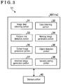
- FIG. 3 is an exemplary and schematic block diagram of the ECU 11 .
- the ECU 11 may function as the image processing apparatus in which the hardware and the software (the program) cooperate with each other.
- the ECU 11 may include the display control portion 11 e and/or the audio control portion 11 f as illustrated in FIG. 1 , and the ECU 11 may also include an image processing portion 30 and a storage portion 40 as illustrated in FIG. 3 .
- the image processing portion 30 may be configured by the CPU 11 a , for example. In this case, the CPU 11 a functions as various portions of the image processing portion 30 .
- the various portions include an image data obtaining portion 31 , a data obtaining portion 32 , a partition line detection portion 33 , a marking image generation portion 34 , an output image generation portion 35 , an object detection portion 36 , an attention image generation portion 37 and a variably-setting portion 38 , for example.
- the storage portion 40 includes the ROM 11 b , the RA 11 c and the flash memory 11 d . At least part of the image processing performed at the image processing portion 30 may be performed at the display control portion 11 e .
- Each of the portions of the image processing portion 30 may correspond to a module of the program and/or at least part of the image processing portion 30 may be configured as the hardware.
- the image data obtaining portion 31 obtains data of plural captured images taken by the plural imaging portions 12 .
- the data obtaining portion 32 obtains data other than the captured image.
- data includes data inputted by the input portions 24 b , 10 a and/or data of detection results of sensors, for example.
- the partition line detection portion 33 detects a partition line from the data of the captured images taken by the imaging portion 12 by way of image processing.
- the partition line may be detected on the basis of whether or not a condition is satisfied, the condition which includes, for example, a position, a size, a shape, an inclination and a color of the image performed with grouping and labeling, for example.
- the marking image generation portion 34 generates a marking image which is to be included, together with the captured image, in the output image.
- the marking image is added for the purpose of a reference for the user to grasp positions of an own vehicle and the surroundings, and/or a distance from the own vehicle to the surroundings, in the output image.
- the output image generation portion 35 generates the output image including the captured image and the marking image.
- FIG. 4 is a view illustrating an example of the output image Io.
- the output image Io includes a captured image Ic and a marking image Ii (Ii 0 ).
- the captured image Ic is an image based on the captured image taken by the imaging portion 12 provided at the door mirror, and the captured image Ic is made like a mirror image or mapped image reflected in the door mirror.
- an infinite convergence point of the captured image Ic is set at the upper left side of a display region, and the front side in a vehicle front-and-rear direction extends from the convergence point in a radiation direction.
- the captured image Ic includes an image Iv of the vehicle 1 (the own vehicle) including an end portion 2 a of the vehicle body 2 in the vehicle width direction, an image Ib of other vehicle 3 (an object) and an image Id of the partition line, for example.
- the captured image Ic may be an image converted with, for example, a coordinate conversion, a viewpoint conversion, a projection conversion, and/or may be an image on which image processing has been performed, the image processing which includes adjustment of brightness, definition, size, for example.
- the marking image Ii 0 is a line (a line segment) extended in the vehicle width direction.
- Plural marking images Ii 0 are arranged to be spaced away from each other in the vehicle front-and-rear direction, for example, to be equally spaced away from each other.
- the marking image Ii may be a transparent image through which the captured image Ic is transmitted.
- the user easily grasps a distance and/or a position of the other vehicle 3 relative to the vehicle 1 (the own vehicle) due to the marking image Ii 0 .
- the user easily grasps a distance between the vehicle 1 and the other vehicle 3 in the vehicle width direction due to the image Id of the partition line.
- the user can easily grasp the distance in the vehicle width direction from the vehicle 1 to the other vehicle 3 on the basis of the image Id of the partition line.
- the user cannot easily grasp the distance in the vehicle width direction from the vehicle 1 to the other vehicle 3 .
- the marking image generation portion 34 in a case where the partition line is not detected at the partition line detection portion 33 , the marking image generation portion 34 generates the marking image Ii 1 which is positioned in the vehicle width direction relative to the vehicle 1 and is arranged along the vehicle front-and-rear direction.
- An example of the output image Io in the above-described case is illustrated in FIG. 5 .
- the above-described output image Io includes the captured image Ic, the marking image Ii 0 along the vehicle width direction, and the marking image Ii 1 along the vehicle front-and-rear direction.
- the user easily grasps the distance from the vehicle 1 to the other vehicle 3 in the vehicle width direction by referring to the marking image Ii 1 even in a case where the image of the partition line is not easily seen.
- the marking image Ii 1 indicates a line L 1 (a first line) which is away from the end portion 2 a of the vehicle body 2 in the vehicle width direction by a distance D and is arranged along the vehicle front-and-rear direction, on a ground surface Gr which is flat and on which the vehicle 1 is placed.
- the distance D is equal to or longer than a vehicle width W of the vehicle 1 .
- the marking image Ii 1 is a band-shaped region which is along the line L 1 and a center of which corresponds to the line L 1 .
- the marking image generation portion 34 is an example of an additional-image generation portion.
- the marking image Ii is an example of an additional image added to the captured image Ic.
- the marking image Ii 1 is an example of a first marking image.
- the object detection portion 36 detects, from the captured image Ic, an object which is positioned within a predetermined distance from the vehicle 1 (the own vehicle), and such an object includes the other vehicle 3 , for example.
- the object may be detected on the basis of whether or not a condition is satisfied, the condition which includes, for example, a position, a size, a shape, an inclination and a color of the image performed with grouping and labeling, by image processing in the data of the captured image Ic.
- the object detection portion 36 may detect the object positioned within the predetermined distance from the vehicle 1 on the basis of the detection result of the non-contact measurement apparatus 13 .
- the distance to the object which is to be detected by the object detection portion 36 may be set arbitrarily.
- the attention image generation portion 37 In a case where the object detected by the object detection portion 36 is positioned within the predetermined distance from the vehicle 1 , the attention image generation portion 37 generates an attention image indicating the object. In this case, the output image generation portion 35 includes the attention image into the output image Io.
- FIG. 6 is a view illustrating an example of the output image Io by the image display system 10 .
- the output image Io includes the captured image Ic, the marking image Ii 0 arranged along the vehicle width direction, and the marking image Ii 1 arranged along the vehicle front-and-rear direction, in a similar manner to the example of FIG. 5 .
- the output image Io illustrated in FIG. 6 includes an attention image Ie corresponding to the other vehicle 3 .
- the attention image Ie is generated to correspond to an object which is extracted from the captured image Ic via the image processing and includes a size that is equal to or larger than a predetermined size.
- FIG. 6 is a view illustrating an example of the output image Io by the image display system 10 .
- the output image Io includes the captured image Ic, the marking image Ii 0 arranged along the vehicle width direction, and the marking image Ii 1 arranged along the vehicle front-and-rear direction, in a similar manner to the example of FIG. 5 .
- the attention image Ie is a line including a predetermined width and superimposed on an edge of the other vehicle 3 serving as the object. Specifications, including, a kind of line, a shape and brightness, of the attention image Ie are different from specifications of the marking images Ii 0 , Ii 1 . Accordingly, the user can easily grasp the object, for example, the other vehicle 3 , which is closer or nearer than the predetermined distance.
- the attention image generation portion 37 may switch whether or not the attention image is to be included, in accordance with large or small relative to the magnitude of the distance in the vehicle width direction from the object to the first line in the vehicle width direction.
- the attention image generation portion 37 may generate the attention image Ie and the output image generation portion 35 may include the attention image Ie into the output image Io.
- the attention image generation portion 37 is an example of the additional-image generation portion.
- the attention image Ie is an example of a first additional image.
- FIGS. 7 to 9 is a view illustrating an example of the output image Io by the image display system 10 .
- the marking image Ii 2 illustrated in the example of FIG. 7 indicates a second line L 2 arranged between the end portion 2 a of the vehicle body 2 (the vehicle 1 ) in the vehicle width direction and the first line L 1 corresponding to the marking image Ii 1 ( FIGS. 5 and 6 ), and the second line L 2 is arranged along the vehicle front-and-rear direction.
- the marking image Ii 2 is an example of a second marking image.
- the example of the output image Io in FIG. 8 includes the marking image Ii 1 which is similar to the marking image indicated in each of FIGS. 5 and 6 , and the marking image Ii 2 which is similar to the marking image indicated in FIG.
- the example of the output image Io in FIG. 9 includes the marking image Ii 3 which includes a wider band shape.
- An end portion of the marking image Ii 3 overlaps with the first line L 1 corresponding to the marking image Ii 1 ( FIGS. 5 and 6 ), and another end portion of the marking image Ii 3 , the end portion which is at a close side to the vehicle 1 , overlaps with the second line L 2 corresponding to the marking image Ii 2 ( FIGS. 7 and 8 ).
- the marking image Ii 3 is an example of a third marking image.
- the marking image Ii can be indicated in various manners.
- the marking image Ii 1 , Ii 2 , Ii 3 may be included in the output image Io in a case where the partition line is not detected by the partition line detection portion 33 , and does not need to be included in the output image Io in a case where the partition line is detected.
- the marking image Ii 1 , Ii 2 , Ii 3 may be included in the output image Io regardless of the detection result of the partition line by the partition line detection portion 33 .
- the variably-setting portion 38 may change the marking image Ii to be included in the output image Io.
- the change of the marking image Ii which is made by the variably-setting portion 38 may be performed on the basis of data inputted via operation performed to the input portions 24 b , 10 a by the user.
- the marking image Ii which is selected according to preference of the user is set.
- the variably-setting portion 38 may change the marking image Ii depending on the detection results, the signal and/or the data by the sensor and/or device of the vehicle 1 .
- the sensor and/or device include the non-contact measurement apparatus 13 , the steering angle sensors 14 , 15 a , the GPS 16 , the brake sensor 18 a , the accelerator sensor 19 , the torque sensor 20 a , the shift sensor 21 and the direction indicator 22 , for example.
- the marking image generation portion 34 (the additional-image generation portion) generates the marking image Ii 1 , Ii 2 , Ii 3 (the additional image) positioned in the vehicle width direction of the vehicle 1 so as to be arranged along the vehicle front-and-rear direction.
- the output image generation portion 35 causes the marking image Ii 1 , Ii 2 , Ii 3 to be included into the output image Io.
- the user easily grasps a position of the vehicle 1 relative to the surroundings and/or a distance from the vehicle 1 to the surroundings, by reference to the marking image Ii 1 , Ii 2 , Ii 3 .
- the output image generation portion 35 causes the marking image Ii 1 , Ii 2 , Ii 3 to be included in the output image Io in a case where the partition line detection portion has not detected the partition line.
- the user can easily grasp the positions of the vehicle 1 and the surroundings relative to each other and/or the distance from the vehicle 1 to the surroundings by referring to the marking image Ii 1 , Ii 2 , Ii 3 .
- the marking image Ii included in the output image Io includes the marking image Ii 1 (the first marking image) indicating the first line L 1 .
- the first line L 1 is apart from the end portion 2 a of the vehicle body 2 (the vehicle 1 ) in the vehicle width direction by the distance D equal to or larger than the vehicle width W of the vehicle 1 , and is arranged along the vehicle front-and-rear direction. Accordingly, for example, the use easily grasps the distance from the vehicle 1 (the own vehicle) to the other vehicle 3 and/or the object in the vehicle width direction, by comparing the other vehicle 3 and/the object with the first line L 1 .
- the marking image Ii included in the output image Io includes the marking image Ii 2 (the second marking image).
- the marking image Ii 2 indicates the second line L 2 that is arranged in the vehicle front-and-rear direction and is arranged between the end portion 2 a of the vehicle body 2 (the vehicle 1 ) in the vehicle width direction and the first line L 1 . Accordingly, for example, the user grasps even more easily the distance from the vehicle 1 (the own vehicle) to the other vehicle 3 and/or to the object in the vehicle width direction, by comparing the other vehicle 3 and/or the object with the first line L 1 and the second line L 2 .
- the marking image Ii included in the output image Io includes the marking image Ii 3 (the third marking image) indicating the band-shaped region positioned in the vehicle width direction of the vehicle 1 and extended in the vehicle front-and-rear direction. Accordingly, for example, the use grasps even more easily the distance from the vehicle 1 (the own vehicle) to the other vehicle 3 and/or to the object in the vehicle width direction, by comparing the other vehicle 3 and/or the object with the band-shaped region positioned between the first line L 1 and the second line L 2 .
- the output image Io includes the attention image Ie (the first additional image) indicating the object positioned within the predetermined distance (for example, W) from the vehicle 1 . Accordingly, for example, due to the attention image Ie, the user easily grasps the presence of the object which is close to the vehicle 1 (the own vehicle).
- the aforementioned embodiment of the present invention is an example and is not intended to limit the scope of the invention.
- the embodiment may be carried out in other various modes, and various omissions, replacements, combinations and changes may be made without departing from the scope of the invention.
- the embodiment may be carried out in a state where the configurations and/or shapes in each embodiment are partly changed with each other.
- the specifications for example, a configuration or structure, a kind, a direction, a shape, a size, a length, a width, a thickness, a height, the number, an arrangement, a position, a color, a pattern
- each configuration and/or shape can be appropriately changed and be carried out.
- the output image may be displayed on plural display apparatuses and/or may be displayed on a display apparatus which is separate from the navigation system, for example.
- the display apparatus may be an apparatuses which reflects an image onto, for example, a windshield and/or a screen inside a vehicle cabin.
- the display apparatus may be a display panel provided at the dashboard and/or a center console inside the vehicle cabin, for example.
- the display panel may be provided at a cockpit module, an instrumental panel and/or a fascia, for example.
Landscapes
- Engineering & Computer Science (AREA)
- Multimedia (AREA)
- Signal Processing (AREA)
- Mechanical Engineering (AREA)
- Physics & Mathematics (AREA)
- General Physics & Mathematics (AREA)
- Theoretical Computer Science (AREA)
- Closed-Circuit Television Systems (AREA)
- Traffic Control Systems (AREA)
- Image Processing (AREA)
- Fittings On The Vehicle Exterior For Carrying Loads, And Devices For Holding Or Mounting Articles (AREA)
Abstract
Description
Claims (4)
Applications Claiming Priority (3)
| Application Number | Priority Date | Filing Date | Title |
|---|---|---|---|
| JP2015-192827 | 2015-09-30 | ||
| JP2015192827A JP6555058B2 (en) | 2015-09-30 | 2015-09-30 | Image processing apparatus for vehicle |
| PCT/JP2016/077188 WO2017057007A1 (en) | 2015-09-30 | 2016-09-14 | Image processing device for vehicles |
Publications (2)
| Publication Number | Publication Date |
|---|---|
| US20190023181A1 US20190023181A1 (en) | 2019-01-24 |
| US10807529B2 true US10807529B2 (en) | 2020-10-20 |
Family
ID=58423545
Family Applications (1)
| Application Number | Title | Priority Date | Filing Date |
|---|---|---|---|
| US15/755,759 Active 2037-02-12 US10807529B2 (en) | 2015-09-30 | 2016-09-14 | Driving assistant apparatus with lane marking |
Country Status (5)
| Country | Link |
|---|---|
| US (1) | US10807529B2 (en) |
| EP (1) | EP3358841B1 (en) |
| JP (1) | JP6555058B2 (en) |
| CN (1) | CN107925747B (en) |
| WO (1) | WO2017057007A1 (en) |
Families Citing this family (3)
| Publication number | Priority date | Publication date | Assignee | Title |
|---|---|---|---|---|
| JP2021016101A (en) * | 2019-07-12 | 2021-02-12 | トヨタ自動車株式会社 | Periphery monitoring device for vehicle |
| EP3785994A1 (en) * | 2019-08-29 | 2021-03-03 | Ningbo Geely Automobile Research & Development Co. Ltd. | A system and method for highlighting of an object to a vehicle occupant |
| US20230036952A1 (en) * | 2020-01-07 | 2023-02-02 | The United States Of America,As Represented By The Secretary,Department Of Health And Human Services | Methods of producing t cell populations using induced pluripotent stem cells |
Citations (9)
| Publication number | Priority date | Publication date | Assignee | Title |
|---|---|---|---|---|
| US20070290823A1 (en) | 2006-06-14 | 2007-12-20 | Honda Motor Co., Ltd. | Driving assistance system for appropriately making the driver recognize another vehicle behind or next to present vehicle |
| JP2009029203A (en) | 2007-07-25 | 2009-02-12 | Honda Motor Co Ltd | Driving assistance device |
| WO2010080610A1 (en) | 2008-12-19 | 2010-07-15 | Delphi Technologies, Inc. | Electronic side view display system |
| US20110293145A1 (en) | 2009-04-23 | 2011-12-01 | Panasonic Corporation | Driving support device, driving support method, and program |
| DE102012022486A1 (en) | 2012-11-19 | 2013-08-01 | Daimler Ag | Method for operating driver assistance system of passenger car, involves determining potential hazard due to change of lane by recognition of vehicle in lane, and providing mark in captured portion of image based on potential hazard |
| JP5562311B2 (en) | 2011-10-11 | 2014-07-30 | 本田技研工業株式会社 | Vehicle driving support device |
| US20140267415A1 (en) * | 2013-03-12 | 2014-09-18 | Xueming Tang | Road marking illuminattion system and method |
| WO2015079623A1 (en) | 2013-11-27 | 2015-06-04 | 株式会社デンソー | Driving support device |
| US20170083774A1 (en) * | 2015-09-23 | 2017-03-23 | Magna Electronics Inc. | Vehicle vision system with detection enhancement using light control |
Family Cites Families (4)
| Publication number | Priority date | Publication date | Assignee | Title |
|---|---|---|---|---|
| DE102005048336A1 (en) * | 2005-10-10 | 2007-04-12 | Robert Bosch Gmbh | Method and system for assisting the driver of a motor vehicle in recognizing the surroundings of the motor vehicle |
| JP4733545B2 (en) * | 2006-03-27 | 2011-07-27 | 富士重工業株式会社 | Lane recognition device |
| JP2009116723A (en) * | 2007-11-08 | 2009-05-28 | Denso Corp | Lane change support system |
| DE102012002149B3 (en) * | 2012-02-04 | 2013-06-20 | Audi Ag | Method for visualizing the environment of a motor vehicle and associated motor vehicle |
-
2015
- 2015-09-30 JP JP2015192827A patent/JP6555058B2/en active Active
-
2016
- 2016-09-14 CN CN201680050326.2A patent/CN107925747B/en active Active
- 2016-09-14 WO PCT/JP2016/077188 patent/WO2017057007A1/en not_active Ceased
- 2016-09-14 US US15/755,759 patent/US10807529B2/en active Active
- 2016-09-14 EP EP16851181.4A patent/EP3358841B1/en active Active
Patent Citations (11)
| Publication number | Priority date | Publication date | Assignee | Title |
|---|---|---|---|---|
| US20070290823A1 (en) | 2006-06-14 | 2007-12-20 | Honda Motor Co., Ltd. | Driving assistance system for appropriately making the driver recognize another vehicle behind or next to present vehicle |
| JP2007334566A (en) | 2006-06-14 | 2007-12-27 | Honda Motor Co Ltd | Driving assistance device |
| JP2009029203A (en) | 2007-07-25 | 2009-02-12 | Honda Motor Co Ltd | Driving assistance device |
| WO2010080610A1 (en) | 2008-12-19 | 2010-07-15 | Delphi Technologies, Inc. | Electronic side view display system |
| US20110293145A1 (en) | 2009-04-23 | 2011-12-01 | Panasonic Corporation | Driving support device, driving support method, and program |
| JP5562311B2 (en) | 2011-10-11 | 2014-07-30 | 本田技研工業株式会社 | Vehicle driving support device |
| DE102012022486A1 (en) | 2012-11-19 | 2013-08-01 | Daimler Ag | Method for operating driver assistance system of passenger car, involves determining potential hazard due to change of lane by recognition of vehicle in lane, and providing mark in captured portion of image based on potential hazard |
| US20140267415A1 (en) * | 2013-03-12 | 2014-09-18 | Xueming Tang | Road marking illuminattion system and method |
| WO2015079623A1 (en) | 2013-11-27 | 2015-06-04 | 株式会社デンソー | Driving support device |
| US20160300491A1 (en) * | 2013-11-27 | 2016-10-13 | Denso Corporation | Driving support apparatus |
| US20170083774A1 (en) * | 2015-09-23 | 2017-03-23 | Magna Electronics Inc. | Vehicle vision system with detection enhancement using light control |
Non-Patent Citations (2)
| Title |
|---|
| Communication dated Jul. 3, 2018, from the European Patent Office in counterpart European Application No. 16851181.4. |
| International Search Report for PCT/JP2016/077188, dated Nov. 22, 2016. |
Also Published As
| Publication number | Publication date |
|---|---|
| EP3358841A4 (en) | 2018-08-08 |
| JP6555058B2 (en) | 2019-08-07 |
| EP3358841A1 (en) | 2018-08-08 |
| CN107925747B (en) | 2020-08-25 |
| US20190023181A1 (en) | 2019-01-24 |
| CN107925747A (en) | 2018-04-17 |
| WO2017057007A1 (en) | 2017-04-06 |
| JP2017069749A (en) | 2017-04-06 |
| EP3358841B1 (en) | 2020-06-10 |
Similar Documents
| Publication | Publication Date | Title |
|---|---|---|
| US10474898B2 (en) | Image processing apparatus for vehicle | |
| JP6056612B2 (en) | Image display control device and image display system | |
| JP6096156B2 (en) | Parking assistance device | |
| JP6380410B2 (en) | Image display control device and image display system | |
| US20170305345A1 (en) | Image display control apparatus and image display system | |
| US10495458B2 (en) | Image processing system for vehicle | |
| US20170259812A1 (en) | Parking assistance device and parking assistance method | |
| US20160114795A1 (en) | Parking assist system and parking assist method | |
| US20170259831A1 (en) | Driving assistance device and driving assistance system | |
| JP2014198531A (en) | Image display controller, image display system, and display unit | |
| CN107791951B (en) | Display control device | |
| JP6554866B2 (en) | Image display control device | |
| JP6413477B2 (en) | Image display control device and image display system | |
| US10807529B2 (en) | Driving assistant apparatus with lane marking | |
| US20200084395A1 (en) | Periphery monitoring device | |
| US10922977B2 (en) | Display control device | |
| US20200035207A1 (en) | Display control apparatus | |
| WO2017056989A1 (en) | Image processing device for vehicles | |
| JP2014000921A (en) | Vehicle periphery monitoring device, vehicle periphery monitoring method and program | |
| JP6601097B2 (en) | Display control device | |
| JP2016060237A (en) | Parking assistance device and parking assistance system |
Legal Events
| Date | Code | Title | Description |
|---|---|---|---|
| AS | Assignment |
Owner name: AISIN SEIKI KABUSHIKI KAISHA, JAPAN Free format text: ASSIGNMENT OF ASSIGNORS INTEREST;ASSIGNOR:WATANABE, KAZUYA;REEL/FRAME:045052/0252 Effective date: 20171113 |
|
| FEPP | Fee payment procedure |
Free format text: ENTITY STATUS SET TO UNDISCOUNTED (ORIGINAL EVENT CODE: BIG.); ENTITY STATUS OF PATENT OWNER: LARGE ENTITY |
|
| STPP | Information on status: patent application and granting procedure in general |
Free format text: DOCKETED NEW CASE - READY FOR EXAMINATION |
|
| STPP | Information on status: patent application and granting procedure in general |
Free format text: NON FINAL ACTION MAILED |
|
| STPP | Information on status: patent application and granting procedure in general |
Free format text: RESPONSE TO NON-FINAL OFFICE ACTION ENTERED AND FORWARDED TO EXAMINER |
|
| STPP | Information on status: patent application and granting procedure in general |
Free format text: FINAL REJECTION MAILED |
|
| STPP | Information on status: patent application and granting procedure in general |
Free format text: NOTICE OF ALLOWANCE MAILED -- APPLICATION RECEIVED IN OFFICE OF PUBLICATIONS |
|
| STCF | Information on status: patent grant |
Free format text: PATENTED CASE |
|
| MAFP | Maintenance fee payment |
Free format text: PAYMENT OF MAINTENANCE FEE, 4TH YEAR, LARGE ENTITY (ORIGINAL EVENT CODE: M1551); ENTITY STATUS OF PATENT OWNER: LARGE ENTITY Year of fee payment: 4 |