US10747856B2 - Setting apparatus, setting method, storage medium, and terminal apparatus - Google Patents
Setting apparatus, setting method, storage medium, and terminal apparatus Download PDFInfo
- Publication number
- US10747856B2 US10747856B2 US15/834,318 US201715834318A US10747856B2 US 10747856 B2 US10747856 B2 US 10747856B2 US 201715834318 A US201715834318 A US 201715834318A US 10747856 B2 US10747856 B2 US 10747856B2
- Authority
- US
- United States
- Prior art keywords
- information
- operator
- authorization
- input
- setting
- Prior art date
- Legal status (The legal status is an assumption and is not a legal conclusion. Google has not performed a legal analysis and makes no representation as to the accuracy of the status listed.)
- Active, expires
Links
- 238000000034 method Methods 0.000 title claims description 115
- 238000013475 authorization Methods 0.000 claims abstract description 153
- 238000013461 design Methods 0.000 claims description 11
- 238000012360 testing method Methods 0.000 description 123
- 238000012937 correction Methods 0.000 description 25
- 238000004886 process control Methods 0.000 description 20
- 238000010586 diagram Methods 0.000 description 14
- 238000004891 communication Methods 0.000 description 12
- 101000911772 Homo sapiens Hsc70-interacting protein Proteins 0.000 description 10
- 238000012544 monitoring process Methods 0.000 description 10
- 101000661807 Homo sapiens Suppressor of tumorigenicity 14 protein Proteins 0.000 description 9
- 230000006870 function Effects 0.000 description 9
- 101001139126 Homo sapiens Krueppel-like factor 6 Proteins 0.000 description 8
- 101000710013 Homo sapiens Reversion-inducing cysteine-rich protein with Kazal motifs Proteins 0.000 description 7
- 230000005540 biological transmission Effects 0.000 description 3
- 239000012530 fluid Substances 0.000 description 3
- 108090000237 interleukin-24 Proteins 0.000 description 3
- 239000004973 liquid crystal related substance Substances 0.000 description 3
- 238000004519 manufacturing process Methods 0.000 description 3
- 230000002159 abnormal effect Effects 0.000 description 2
- 238000011989 factory acceptance test Methods 0.000 description 2
- 238000013507 mapping Methods 0.000 description 2
- 238000005259 measurement Methods 0.000 description 2
- 230000002265 prevention Effects 0.000 description 2
- 238000012026 site acceptance test Methods 0.000 description 2
- 102100036848 C-C motif chemokine 20 Human genes 0.000 description 1
- 101000713099 Homo sapiens C-C motif chemokine 20 Proteins 0.000 description 1
- 230000005856 abnormality Effects 0.000 description 1
- 230000006399 behavior Effects 0.000 description 1
- 238000009529 body temperature measurement Methods 0.000 description 1
- 238000011109 contamination Methods 0.000 description 1
- 230000006378 damage Effects 0.000 description 1
- 230000007613 environmental effect Effects 0.000 description 1
- 230000010354 integration Effects 0.000 description 1
- 238000012545 processing Methods 0.000 description 1
- 238000013102 re-test Methods 0.000 description 1
- 230000008439 repair process Effects 0.000 description 1
Images


Classifications
-
- G—PHYSICS
- G05—CONTROLLING; REGULATING
- G05B—CONTROL OR REGULATING SYSTEMS IN GENERAL; FUNCTIONAL ELEMENTS OF SUCH SYSTEMS; MONITORING OR TESTING ARRANGEMENTS FOR SUCH SYSTEMS OR ELEMENTS
- G05B19/00—Programme-control systems
- G05B19/02—Programme-control systems electric
- G05B19/04—Programme control other than numerical control, i.e. in sequence controllers or logic controllers
- G05B19/042—Programme control other than numerical control, i.e. in sequence controllers or logic controllers using digital processors
- G05B19/0428—Safety, monitoring
-
- G—PHYSICS
- G06—COMPUTING; CALCULATING OR COUNTING
- G06F—ELECTRIC DIGITAL DATA PROCESSING
- G06F21/00—Security arrangements for protecting computers, components thereof, programs or data against unauthorised activity
- G06F21/30—Authentication, i.e. establishing the identity or authorisation of security principals
- G06F21/31—User authentication
-
- G—PHYSICS
- G05—CONTROLLING; REGULATING
- G05B—CONTROL OR REGULATING SYSTEMS IN GENERAL; FUNCTIONAL ELEMENTS OF SUCH SYSTEMS; MONITORING OR TESTING ARRANGEMENTS FOR SUCH SYSTEMS OR ELEMENTS
- G05B19/00—Programme-control systems
- G05B19/02—Programme-control systems electric
- G05B19/04—Programme control other than numerical control, i.e. in sequence controllers or logic controllers
- G05B19/042—Programme control other than numerical control, i.e. in sequence controllers or logic controllers using digital processors
- G05B19/0423—Input/output
-
- G—PHYSICS
- G05—CONTROLLING; REGULATING
- G05B—CONTROL OR REGULATING SYSTEMS IN GENERAL; FUNCTIONAL ELEMENTS OF SUCH SYSTEMS; MONITORING OR TESTING ARRANGEMENTS FOR SUCH SYSTEMS OR ELEMENTS
- G05B19/00—Programme-control systems
- G05B19/02—Programme-control systems electric
- G05B19/04—Programme control other than numerical control, i.e. in sequence controllers or logic controllers
- G05B19/042—Programme control other than numerical control, i.e. in sequence controllers or logic controllers using digital processors
- G05B19/0426—Programming the control sequence
-
- G—PHYSICS
- G06—COMPUTING; CALCULATING OR COUNTING
- G06F—ELECTRIC DIGITAL DATA PROCESSING
- G06F21/00—Security arrangements for protecting computers, components thereof, programs or data against unauthorised activity
- G06F21/30—Authentication, i.e. establishing the identity or authorisation of security principals
- G06F21/31—User authentication
- G06F21/40—User authentication by quorum, i.e. whereby two or more security principals are required
-
- H—ELECTRICITY
- H04—ELECTRIC COMMUNICATION TECHNIQUE
- H04L—TRANSMISSION OF DIGITAL INFORMATION, e.g. TELEGRAPHIC COMMUNICATION
- H04L63/00—Network architectures or network communication protocols for network security
- H04L63/10—Network architectures or network communication protocols for network security for controlling access to devices or network resources
-
- H—ELECTRICITY
- H04—ELECTRIC COMMUNICATION TECHNIQUE
- H04L—TRANSMISSION OF DIGITAL INFORMATION, e.g. TELEGRAPHIC COMMUNICATION
- H04L63/00—Network architectures or network communication protocols for network security
- H04L63/20—Network architectures or network communication protocols for network security for managing network security; network security policies in general
-
- G—PHYSICS
- G05—CONTROLLING; REGULATING
- G05B—CONTROL OR REGULATING SYSTEMS IN GENERAL; FUNCTIONAL ELEMENTS OF SUCH SYSTEMS; MONITORING OR TESTING ARRANGEMENTS FOR SUCH SYSTEMS OR ELEMENTS
- G05B2219/00—Program-control systems
- G05B2219/20—Pc systems
- G05B2219/21—Pc I-O input output
- G05B2219/21012—Configurable I-O
-
- G—PHYSICS
- G05—CONTROLLING; REGULATING
- G05B—CONTROL OR REGULATING SYSTEMS IN GENERAL; FUNCTIONAL ELEMENTS OF SUCH SYSTEMS; MONITORING OR TESTING ARRANGEMENTS FOR SUCH SYSTEMS OR ELEMENTS
- G05B2219/00—Program-control systems
- G05B2219/20—Pc systems
- G05B2219/21—Pc I-O input output
- G05B2219/21062—Pc and I-O bus manager and network nodes linked to I-O clusters
-
- G—PHYSICS
- G05—CONTROLLING; REGULATING
- G05B—CONTROL OR REGULATING SYSTEMS IN GENERAL; FUNCTIONAL ELEMENTS OF SUCH SYSTEMS; MONITORING OR TESTING ARRANGEMENTS FOR SUCH SYSTEMS OR ELEMENTS
- G05B2219/00—Program-control systems
- G05B2219/20—Pc systems
- G05B2219/24—Pc safety
- G05B2219/24024—Safety, surveillance
-
- G—PHYSICS
- G05—CONTROLLING; REGULATING
- G05B—CONTROL OR REGULATING SYSTEMS IN GENERAL; FUNCTIONAL ELEMENTS OF SUCH SYSTEMS; MONITORING OR TESTING ARRANGEMENTS FOR SUCH SYSTEMS OR ELEMENTS
- G05B2219/00—Program-control systems
- G05B2219/20—Pc systems
- G05B2219/25—Pc structure of the system
- G05B2219/25428—Field device
-
- G—PHYSICS
- G05—CONTROLLING; REGULATING
- G05B—CONTROL OR REGULATING SYSTEMS IN GENERAL; FUNCTIONAL ELEMENTS OF SUCH SYSTEMS; MONITORING OR TESTING ARRANGEMENTS FOR SUCH SYSTEMS OR ELEMENTS
- G05B2219/00—Program-control systems
- G05B2219/30—Nc systems
- G05B2219/36—Nc in input of data, input key till input tape
- G05B2219/36542—Cryptography, encrypt, access, authorize with key, code, password
Definitions
- the present invention relates to a setting apparatus, a setting method, a storage medium, and a terminal apparatus.
- process control systems controlling various state amounts (for example, pressure, a temperature, a flow rate, and the like) in industrial processes are built, and high-level automatic operations have been realized.
- a process control system has a configuration in which site devices (a measuring instrument and an operation device) called field devices are connected to a controller through an I/O module, and, the controller controls an operation device (for example, an actuator) in accordance with a measurement result acquired by a measuring instrument (for example, a sensor) such that the above-described various state amounts are controlled.
- Such a process control system is built through a factory acceptance test (FAT), a site acceptance test (SAT), and a system integration test (SIT).
- FAT factory acceptance test
- SAT site acceptance test
- SIT system integration test
- Patent Document 1 In Japanese Unexamined Patent Application, First Publication No. 2016-081415 (hereinafter, referred to as “Patent Document 1”), an example of a method of building a process control system in the related art has been disclosed. More specifically, in Patent Document 1 presented below, an I/O module and field devices are installed to be wired at a site, and a method of setting the I/O module and the field devices by using a setting device connected to the I/O module in a state in which a controller is not connected to the I/O module has been disclosed. By using this method, a time required for building a process control system can be configured to be shorter than that of a conventional case.
- a process control system is built in relation with various operators in each process.
- the number of operators relating to the building is also increased.
- an I/O module and field devices are set by using the method disclosed in the above-described Patent Document 1
- a situation in which a plurality of operators perform setting by using a plurality of setting apparatuses is considered to occur more frequently.
- One aspect of the present invention provides a setting apparatus, a setting method, a storage medium, and a terminal apparatus capable of effectively preventing a wasteful operation or an erroneous setting and appropriately managing an operator in accordance with his or her skills.
- a setting apparatus may include an authenticator configured to authenticate an operator using a setting apparatus, the setting apparatus performing a setting of an I/O module including a plurality of first connectors to which field devices are connectable and a second connector to which a controller controlling the field devices is connectable, and an authorizer configured to assign operation authorization to the operator authenticated by the authenticator on the basis of previously set authorization definition information, the operation authorization allowing the operator to perform at least one operation using the setting apparatus, the authorization definition information including first information and second information, the first information defining whether or not a change of input and output information of the field device connected to each of the first connectors is permitted, the second information defining whether or not a change of each item of the input and output information is permitted on the basis of a role of the operator.
- the second information may include information representing scope of work for each item of the input and output information.
- the scope of work may define which role an operation is assigned to, the operation being associated with each item of the input and output information.
- the authorizer may be configured to assign the operation authorization to the operator on the basis of the scope of work.
- the authorization definition information may further include third information in which the operator and the role of the operator are associated with each other.
- the above-described setting apparatus may further include a storage storing the authorization definition information.
- the authorizer may be configured to assign the operation authorization to the operator on the basis of the authorization definition information read from the storage.
- the first information may be stored in the storage in association with the input and output information of each of the first connectors.
- the above-described setting apparatus may further include an acquirer configured to acquire the authorization definition information from the outside of the setting apparatus.
- the authorizer may be configured to assign to the operator the operation authorization of changing the input and output information of the field device connected to the first connector in which the change of the input and output information is permitted in the first information.
- the authorizer may be configured to assign to the operator the operation authorization of changing the item of the input and output information in which the change of the item is permitted on the basis of the role of the operator in the second information.
- the authorizer may be configured to assign to the operator the operation authorization of changing the item of the input and output information when the change of the item is permitted on the basis of the role of the operator in the second information and the role of the operator is included in the scope of work.
- the authorizer may be configured not to assign to the operator the operation authorization of changing the item of the input and output information when the change of the item is permitted on the basis of the role of the operator in the second information and the role of the operator is not included in the scope of work.
- a setting method may use a setting apparatus performing a setting of an I/O module including a plurality of first connectors to which field devices are connectable and a second connector to which a controller controlling the field devices is connectable.
- the setting method may include authenticating an operator using the setting apparatus, and assigning operation authorization to the operator authenticated on the basis of previously set authorization definition information, the operation authorization allowing the operator to perform at least one operation using the setting apparatus, the authorization definition information including first information and second information, the first information defining whether or not a change of input and output information of the field device connected to each of the first connectors is permitted, the second information defining whether or not a change of each item of the input and output information is permitted on the basis of a role of the operator.
- the second information may include information representing scope of work for each item of the input and output information, the scope of work defining which role an operation is assigned to, the operation being associated with each item of the input and output information.
- Assigning the operation authorization to the operator may include assigning the operation authorization to the operator on the basis of the scope of work.
- the authorization definition information may further include third information in which the operator and the role of the operator are associated with each other.
- the setting apparatus may further include a storage storing the authorization definition information.
- Assigning the operation authorization to the operator may include assigning the operation authorization to the operator on the basis of the authorization definition information read from the storage.
- the first information may be stored in the storage in association with the input and output information of each of the first connectors.
- the above-described setting method may further include acquiring the authorization definition information from the outside of the setting apparatus.
- assigning the operation authorization to the operator may include assigning to the operator the operation authorization of changing the input and output information of the field device connected to the first connector in which the change of the input and output information is permitted in the first information.
- a non-transitory computer-readable storage medium may store a setting program causing a computer to function as a setting apparatus that performs a setting of an I/O module including a plurality of first connectors to which field devices are connectable and a second connector to which a controller controlling the field devices is connectable.
- the setting program may cause the computer to authenticate an operator using the setting apparatus, and assign operation authorization to the operator authenticated on the basis of previously set authorization definition information, the operation authorization allowing the operator to perform at least one operation using the setting apparatus, the authorization definition information including first information and second information, the first information defining whether or not a change of input and output information of the field device connected to each of the first connectors is permitted, the second information defining whether or not a change of each item of the input and output information is permitted on the basis of a role of the operator.
- a terminal apparatus may generate the authorization definition information to be used by the above-described setting apparatus using design information of at least the field devices, the I/O module, and the controller stored in a database.
- the terminal apparatus may be configured to copy the authorization definition information and input the copied authorization definition information into the setting apparatus when the setting apparatus is connected to the terminal apparatus.
- an operator using a setting apparatus is authenticated, and operation authorization of an operation that can be performed by the authenticated operator, by using the setting apparatus is assigned on the basis of previously set authorization definition information.
- the authorization definition information includes, for example, first information defining whether or not a change of input and output information is enabled for each of first connectors disposed in an I/O module and second information defining whether or not a change of content is enabled according to a role of the operator for each item of the input and output information. For this reason, a wasteful operation and an erroneous setting can be effectively prevented, and an operator can be appropriately managed according to his or her skills.
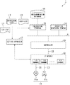
- FIG. 1 is a block diagram showing a whole configuration of a process control system
- FIG. 2 is a block diagram showing a main configuration of an I/O module
- FIG. 3 is a block diagram showing a main configuration of a setting apparatus according to one embodiment of the present invention.
- FIGS. 4A and 4B are diagrams showing examples of an I/O list used by a setting apparatus according to one embodiment of the present invention.
- FIG. 5 is a diagram showing one example of an authorization list used by a setting apparatus according to one embodiment of the present invention.
- FIG. 6 is a diagram showing one example of a user list used by a setting apparatus according to one embodiment of the present invention.
- FIG. 7 is a flowchart showing an operation sequence of various settings performed using a setting apparatus according to one embodiment of the present invention.
- FIG. 8 is a flowchart showing details of a process performed by the setting apparatus in Step S 17 shown in FIG. 7 ;
- FIG. 9 is a flowchart showing details of a process performed by the setting apparatus in Step S 19 shown in FIG. 7 ;
- FIG. 10 is a flowchart showing a process of checking for completion of testing performed according to one embodiment of the present invention.
- FIG. 1 is a block diagram showing a whole configuration of a process control system.
- a process control system 1 includes a field device 11 , an I/O module 12 , a controller 13 , an operation monitoring terminal 14 , an engineering terminal 15 , and an instrumentation database 16 (database).
- the process control system 1 controls an industrial process realized by a plant (not shown in the drawing) by using the controller 13 to control the field devices 11 in accordance with an instruction from the operation monitoring terminal 14 or the like. While details will be described later, the process control system 1 is built while performing various settings of the I/O module 12 and the field device 11 by using the setting apparatus 17 .
- the field device 11 and the I/O module 12 are connected through a transmission line C 1 , and the I/O module 12 and the controller 13 are connected through a cable C 2 .
- the controller 13 , the operation monitoring terminal 14 , the engineering terminal 15 , and the instrumentation database 16 are connected to a control network N.
- the control network N for example, is a network that connects a site of the plant and a monitoring room.
- the field device 11 is a sensor device such as a flowmeter or a temperature sensor, a valve device such as a flow control valve or an opening/closing valve, an actuator device such as a fan or a motor, or any other device installed at the site of the plant.
- a sensor device such as a flowmeter or a temperature sensor
- a valve device such as a flow control valve or an opening/closing valve
- an actuator device such as a fan or a motor, or any other device installed at the site of the plant.
- FIG. 1 shows one sensor device 11 a measuring the flow rate of the fluid and one valve device 11 b controlling (operating) the flow rate of the fluid among a plurality of field devices 11 installed in the plant.
- the I/O module 12 is disposed between the field device 11 and the controller 13 , to which the plurality of field devices 11 can be connected, and processes signals are input/output between the connected field device 11 and the controller 13 .
- the I/O module 12 performs a process of converting a signal acquired from the field device 11 into a signal that can be received by the controller 13 .
- This I/O module 12 may be regarded as a module that connects the plurality of field devices 11 to the controller 13 and relays signals input/output by the field device 11 and signals input/output by the controller 13 . Details of the I/O module 12 will be described later.
- the controller 13 communicates with the field device 11 in accordance with an instruction from the operation monitoring terminal 14 or the like to control the field device 11 . More specifically, the controller 13 acquires a process value measured by a certain field device 11 (for example, the sensor device 11 a ) and calculates and transmits an operation amount of another field device 11 (for example, the valve device 11 b ) to control the other field device 11 (for example, the valve device 11 b ).
- the operation monitoring terminal 14 is a terminal that is operated, for example, by an operator of the plant and is used for monitoring the process. More specifically, the operation monitoring terminal 14 acquires input/output data of the field device 11 from the controller 13 , transmits behaviors of the field device 11 and the controller 13 configuring the process control system 1 to the operator, and controls the controller 13 on the basis of an operator's instruction.
- the engineering terminal 15 generates information to be set in the field device 11 , the I/O module 12 , and the controller 13 on the basis of design information stored in the instrumentation database 16 .
- the design information includes design information of the plant including design information of at least the field device 11 , the I/O module 12 , and the controller 13 in the process control system 1 .
- As the information generated by this engineering terminal 15 there are an I/O list L 1 , an authorization list L 2 , and a user list L 3 (authorization definition information).
- the engineering terminal 15 copies the I/O list L 1 , the authorization list L 2 , and the user list L 3 and outputs the lists to the setting apparatus 17 .
- the I/O list L 1 has information relating to input/output between the field device 11 and the I/O module 12 .
- the I/O list L 1 is not limited to the information relating to the input/output and may include at least one of an operation condition setting specific to the field device, I/O channel protection information, a test result, and the like in addition to the above-described information.
- the authorization list L 2 (second information) is information relating to authorization according to a role of an operator.
- the user list L 3 (third information) is information relating to the operator.
- the reason for generating the authorization list L 2 and the user list L 3 using the engineering terminal 15 is that a range in which the I/O list L 1 can be changed according to the role of the operator is precisely limited. Details of the I/O list L 1 , the authorization list L 2 , and the user list L 3 will be described later.
- the operator's above-described role represents, so to speak, an occupation category of the operator (or skills of the operator) and examples thereof are a system engineer, a field engineer, and a tester.
- the system engineer for example, is an engineer directing design, building, testing, or the like of the process control system 1
- the field engineer for example, is an engineer operating at the site of the plant
- the tester for example, is an engineer performing various tests at the site of the plant.
- the instrumentation database 16 stores the above-described design information referred to by the engineering terminal 15 .
- the instrumentation database 16 may store the same list as the I/O list L 1 generated by the engineering terminal 15 .
- the setting apparatus 17 is an apparatus for performing various settings for the field device 11 and the I/O module 12 by using the I/O list L 1 , the authorization list L 2 , and the user list L 3 acquired from the engineering terminal 15 when the process control system 1 is built.
- the setting apparatus 17 even in a state in which the controller 13 is not connected to the I/O module 12 , setting and adjustment for the field device 11 and the I/O module 12 , a connection test between the field device 11 and the I/O module 12 , and the like can be performed.
- the setting apparatus 17 performs authentication of an operator using the setting apparatus 17 and assigns operation authorization of an operation that can be performed by the authenticated operator using the setting apparatus 17 on the basis of the I/O list L 1 , the authorization list L 2 , and the user list L 3 .
- the assigning of such operation authorization is for appropriately managing the operator in accordance with his or her skills and effectively preventing a wasteful operation and an erroneous setting. Details of the setting apparatus 17 will be described later.
- FIG. 2 is a block diagram showing a main configuration of the I/O module.
- the I/O module 12 includes an I/O channel interface 21 , a control layer interface 22 (second connector), a setting apparatus connection interface 23 , a device setter 24 , a tester 25 , a switch 26 , a switch 27 , and a switch 28 .
- the I/O channel interface 21 includes a plurality of I/O channels CN (first connectors) to which field devices 11 are connected, and exchanges various signals with the field devices 11 connected to the I/O channels CN.
- This I/O channel interface 21 includes a memory M storing an I/O tag T 1 (tag information) set for each of the I/O channels CN by the device setter 24 on the basis of an instruction from the setting apparatus 17 .
- Each of the I/O channels CN can perform an input of an analog signal from the field device 11 , an output of an analog signal to the field device 11 , an input (discrete input) of a digital signal from the field device 11 , and an output (discrete output) of a digital signal to the field device 11 , or perform an input (discrete input) of a digital signal from the field device 11 and an output (discrete output) of a digital signal to the field device 11 .
- One of the above-described inputs/outputs to be performed by the I/O channel CN is set by the device setter 24 on the basis of an instruction from the setting apparatus 17 .
- the control layer interface 22 is connected to the cable C 2 and exchanges various signals with the controller 13 disposed in a control layer through the cable C 2 .
- the setting apparatus connection interface 23 exchanges various signals with the connected setting apparatus 17 through a connection cable, which is not shown in the drawing, or a radio connection.
- a wired interface such as a universal serial bus (USB) or Ethernet (registered trademark) or a radio interface performing radio communication compliant with a radio communication standard such as Wi-Fi (registered trademark) or Bluetooth (registered trademark) may be used.
- the device setter 24 performs various settings of the I/O channel interface 21 and various settings of the field device 11 on the basis of a setting instruction from the setting apparatus 17 that is input through the setting apparatus connection interface 23 or a setting instruction from the controller 13 that is input through the control layer interface 22 .
- the device setter 24 sets the I/O tag T 1 for each of the I/O channels CN on the basis of a setting instruction from the setting apparatus 17 that is input through the setting apparatus connection interface 23 .
- the device setter 24 performs a setting related to input/output of the I/O channel CN by using the above-described I/O tag T 1 on the basis of the setting instruction from the setting apparatus 17 that is input through the setting apparatus connection interface 23 . More specifically, the device setter 24 sets each of the I/O channels CN to perform one of an input of an analog signal from the field device 11 , an output of an analog signal to the field device 11 , an input of a digital signal from the field device 11 , and an output of a digital signal to the field device 11 .
- the device setter 24 performs a setting of the field device 11 connected to the I/O channel CN for which the above-described setting is performed using the above-described I/O tag T 1 on the basis of the setting instruction from the setting apparatus 17 that is input through the setting apparatus connection interface 23 .
- Examples of the setting performed for the field device 11 include a setting of an address (device address) unique to each of the field devices 11 and a setting of an operation condition unique to each of the field devices 11 .
- the tester 25 performs a checking test of states of the I/O channel CN and the field device 11 .
- the tester 25 performs a checking test for checking whether or not the setting relating to the input/output of the I/O channel CN is normally performed, whether or not a connection between the I/O channel CN and the field device 11 is normally performed, or the like.
- the tester 25 performs only a relay of various signals that are transmitted/received between the setting apparatus 17 and the I/O channel interface 21 .
- the switch 26 causes an open state or a closed state between the control layer interface 22 and the device setter 24 and the tester 25 in accordance with an instruction from the switch 28 .
- the switch 27 causes the open state or the closed state between the setting apparatus connection interface 23 and the device setter 24 and the tester 25 in accordance with the instruction from the switch 28 .
- These switches 26 and 27 may be either mechanical switches or switches realized by software.
- the switch 28 sets one of the switches 26 and 27 to be in the closed state and sets the other switch to be in the open state on the basis of an instruction from the controller 13 that is input through the control layer interface 22 or an instruction from the setting apparatus 17 input through the setting apparatus connection interface.
- FIG. 3 is a block diagram showing a main configuration of the setting apparatus according to one embodiment of the present invention.
- the setting apparatus 17 includes an upper layer interface 31 (acquirer), a lower layer interface 32 , a storage 33 , a control processor 34 , and an operation display 35 .
- Such a setting apparatus 17 for example, is realized by a desktop type, notebook type, or tablet type personal computer.
- the upper layer interface 31 is connected to the engineering terminal 15 (higher-rank apparatus) located at a higher rank than the controller 13 and exchanges various kinds of information with the engineering terminal 15 .
- the upper layer interface 31 receives (obtains) the I/O list L 1 , which is information relating to input/output between the field device 11 and the I/O module 12 , the authorization list L 2 , which is information relating to authorization according to a role of an operator, and the user list L 3 (see FIG. 1 ), which is information relating to the operator, from the engineering terminal 15 .
- the upper layer interface 31 may be either directly connected to the engineering terminal 15 or indirectly connected to the engineering terminal 15 through the control network N.
- the higher layer interface 31 may be connected to the engineering terminal 15 that is in an offline state.
- the lower layer interface 32 is connected to the setting apparatus connection interface 23 of the I/O module 12 and exchanges various kinds of information with the I/O module 12 .
- this lower layer interface 32 similar to the setting apparatus connection interface 23 disposed in the above-described I/O module 12 , a wired interface or a radio interface may be used.
- the upper layer interface 31 and the lower layer interface 32 described above may be realized by a single interface.
- the storage 33 includes an external storage device such as a hard disk and stores a device list mapping database DB 1 , a history database DB 2 , and a checklist database DB 3 .
- the storage 33 stores the I/O list L 1 , the authorization list L 2 , and the user list L 3 acquired from the engineering terminal 15 .
- the device list mapping database DB 1 is a database in which various setting values (designed setting values and actual setting values) of the field device 11 and the I/O module 12 , wiring information representing wirings of the field device 11 and the I/O module 12 , positional information representing positions, and the like are stored.
- the history database DB 2 is a database in which operation histories (histories associating each specific piece of operation content and a date and time at which an operation is performed) relating to operations performed for the field device 11 and the I/O module 12 are stored.
- operation histories histories associating each specific piece of operation content and a date and time at which an operation is performed
- the check list database DB 3 is a database in which information (checking information) defining items (check items) to be checked for the field device 11 or the I/O module 12 and a sequence (checking sequence) and a result thereof are stored.
- information checking information
- checking items for example, “input checking,” “output checking,” “input loop checking,” “output loop checking,” and the like are stored.
- “Input checking” and “output checking” are items used for checking types (identifications of a current input, a pulse input, an mV input, a thermocouple input, or the like) of input/output signals.
- the control processor 34 integrally controls the operation of the setting apparatus 17 and performs processes required for performing various settings of the field device 11 and the I/O module 12 .
- This control processor 34 includes a setting instructor 34 a , a setting checker 34 b , a checker 34 c , an I/O tag coupler 34 d , a user authenticator 34 e (an authenticator or an authentication means), and a user authorizer 34 f (an authorizer or an authorization assigning means).
- the setting instructor 34 a performs a setting of instructions for the I/O module 12 and the field device 11 through the lower layer interface 32 by using information of each of the databases stored in the storage 33 .
- the setting checker 34 b performs a checking of instructions for the I/O module 12 and the field device 11 through the lower layer interface 32 .
- the setting checker 34 b compares information acquired from the lower layer interface 32 by performing the checking of instructions with the information of each of the databases stored in the storage 33 . Then, the setting checker 34 b causes the operation display 35 to display a result of the comparison or notifies the engineering terminal 15 of the result through the higher layer interface 31 .
- the checker 34 c similar to the tester 25 of the I/O module 12 , performs a checking test of the states of the I/O channel CN and the field device 11 . More specifically, the checker 34 c performs a checking test of the states of the I/O channel CN and the field device 11 on the basis of the checking information stored in the check list database DB 3 of the storage 33 . For example, the checker 34 c performs a checking test for checking whether or not a setting related to the input/output of the I/O channel CN is normally performed, whether or not a connection between the I/O channel CN and the field device 11 is normally performed, or the like.
- the checker 34 c stores information acquired by adding information (time information) representing a time at which the checking test is performed to information (checking information) acquired by performing the checking test of the states of the I/O channel CN and the field device 11 in the history database DB 2 .
- the reason for storing such information in the history database DB 2 is that a time at which a certain checking test is performed for the I/O channel CN and the field device 11 and a result thereof are stored.
- the checker 34 c causes the operation display 35 to display progress information representing a status of the checking test of the states of the I/O channel CN and the field device 11 or notifies the progress information to the outside (for example, the engineering terminal 15 ) from the upper layer interface 31 .
- the checking test may be performed in parallel for a plurality of I/O modules 12 . As the progress information is displayed on the operation display 35 , the status of the checking test of the I/O module 12 and the field device 11 to which the setting apparatus 17 is connected can be checked.
- the I/O tag coupler 34 d associates an I/O tag T 2 (see FIG. 4B ) used by the controller 13 with the I/O tag T 1 set for each of the I/O channels CN of the I/O module 12 . While details will be described later, the I/O tag T 1 is included in an I/O list L 11 (see FIG. 4A ) forming a part of the I/O list L 1 shown in FIG. 1 , and the I/O tag T 2 is included in an I/O list L 12 (see FIG. 4B ) forming a part of the I/O list L 1 shown in FIG. 1 .
- the reason for associating the I/O tags T 1 and T 2 using the I/O tag coupler 34 d is that input and output information J 1 (see FIG. 4A ) for the I/O channel CN is combined with input and output information J 2 (see FIG. 4B ) for the field device 11 connected to the I/O channel CN.
- the user authenticator 34 e performs authentication of an operator using the setting apparatus 17 .
- the user authenticator 34 e performs the authentication of the operator using the setting apparatus 17 by collating a user ID and a password for authentication input from the operation display 35 with a user ID and a password for authentication that are stored in advance.
- the user authorizer 34 f assigns operation authorization of an operation that can be performed by the operator authenticated by the user authenticator 34 e using the setting apparatus 17 on the basis of the I/O list L 1 , the authorization list L 2 , and the user list L 3 read from the storage 33 . Details of an assignment of specific operation authorization performed by the user authorizer 34 f will be described later.
- the operation display 35 includes, for example, a touch panel type liquid crystal display device having both a display function and an operation function, displays various kinds of information output from the control processor 34 , and, in a case where an operation is performed on a display surface of the liquid crystal display device, outputs an operation signal according to the operation to the control processor 34 .
- a display function and an operation function may be physically divided.
- Each block (the setting instructor 34 a , the setting checker 34 b , the checker 34 c , the I/O tag coupler 34 d , the user authenticator 34 e , and the user authorizer 34 f ) disposed in the above-described control processor 34 is realized as a program used for realizing each function, and the program is executed by a central processing unit (CPU) disposed in a computer.
- CPU central processing unit
- each of the blocks disposed in the control processor 34 is realized by incorporating software and hardware resources.
- the I/O list L 11 shown in FIG. 4A is a list in which the input and output information J 1 and I/O protection information PR (first information) is associated with the I/O tag T 1 set for each of the I/O channels CN of the I/O module 12 .
- the input and output information J 1 is information relating to input/output and the like of the field device 11 connected to each of the I/O channels CN.
- items of the input and output information J 1 include “P&ID tag,” “I/O type,” “communication method,” “device address,” “device model name,” “channel information,” “I/O channel test result,” “field device test result,” and the like.
- P&ID tag is a tag that is used for logically representing each of the I/O channels CN disposed at the I/O module 12 in a piping and instrumentation diagram (P&ID) of a plant.
- I/O type is information that represents the type (input (AI) of an analog signal, output (AO) of an analog signal, input (DI) of a digital signal, output (DO) of a digital signal, or the like) of input/output of the field device 11 .
- “Communication method” is information that represents a communication method used by the field device 11 .
- a communication method using a 4 to 20 mA signal a communication method compliant with HART (registered trademark), and a communication method compliant with Foundation Fieldbus (FF; registered trademark) are shown.
- “Device address” is information representing an address that is assigned to the field device 11
- “device model name” is information representing a model (model name) of the field device 11
- “channel information” is information representing a communication channel used by the field device 11 .
- I/O channel test result is a test result of testing (for example, a checking test of a state) performed for each of the I/O channels CN
- field device test result is a test result of testing (for example, a checking test of a state) performed for the field device 11 connected to each of the I/O channels CN.
- each of the I/O channel test result and the field device test result includes “OK” representing success, “NG” representing failure, “None” representing an indication of no test result, or the like.
- the I/O protection information PR defines whether or not changing (editing) of the input and output information J 1 associated with the I/O tag T 1 is enabled.
- This I/O protection information PR defines whether or not changing of “I/O channel test result” and “field device test result” included in the input and output information J 1 is enabled, and accordingly, the I/O protection information PR also defines whether or not testing of the I/O channel CN to which the I/O tag T 1 is set is enabled. In other words, the I/O protection information PR is for defining whether or not the state of the I/O channel CN is protected.
- the I/O list L 12 shown in FIG. 4B is a list in which the tag T 2 used by the controller 13 for logically identifying each of the I/O channels CN of the I/O module 12 and the input and output information J 2 for the I/O channel CN are associated with each other.
- the items of the input and output information J 2 of each I/O channel CN include “P&ID tag,” “device type,” “I/O type,” “range,” “engineering unit,” and the like.
- the I/O list L 12 may be either a list in which an item of I/O protection information is provided or a list that is integrated with the I/O list L 11 .
- the input and output information J 2 cannot be changed by a field engineer or a tester (an operator whose scope of work to be described later is set to the field side) regardless of the presence/absence of a check of the I/O protection information.
- “P&ID tag” and “I/O type” are similar to those included in the input and output information J 1 of the I/O list L 11 .
- “Device type” is information representing the function of the field device 11 connected to the I/O channel CN. In the example shown in FIG. 4B , a temperature measurement, a flow rate measurement, a flow rate adjustment, and the like are shown as examples.
- “Range” is information representing the range of the magnitude of signals input or output through the I/O channel CN.
- “Engineering unit” is information representing the unit of signals that are input or output through the I/O channel CN. For example, in a case where signals that are input or output through the I/O channel CN are signals representing temperatures, “engineering unit” is defined as “° C.”
- FIG. 5 is a diagram showing one example of the authorization list used by a setting apparatus according to one embodiment of the present invention.
- the authorization list L 2 as shown in FIG. 1 , is generated by the engineering terminal 15 on the basis of the design information stored in the instrumentation database 16 , and is received by the setting apparatus 17 .
- the authorization list L 2 is used for limiting a range in which the I/O list L 1 can be changed in units of items (the I/O tag T 1 , each item of the input and output information J 1 , and the I/O protection information PR) of the I/O list L 1 in accordance with a role of an operator.
- the authorization list L 2 is used for assigning the authorization to change the I/O list L 1 in accordance with the role of the operator in units of the above-described items of the I/O list L 1 .
- the authorization list L 2 is a list in which enable/disable information ED defining whether or not a change of each item of the I/O list L 1 can be performed is associated with an operator's role Q 1 .
- the operator's role Q 1 includes “system engineer,” “field engineer,” and “tester.”
- the enable/disable information ED there is the presence/absence of a permission flag (“checked check box” and “unchecked check box”) for each combination of the operator's role Q 1 and an item of the I/O list L 1 .
- the operator's role “field engineer” may be subdivided for each responsible facility such as a sensor, a valve, a transmitter, or the like, and the authorization may be set for each of the subdivided roles.
- the permission flag In a case where the permission flag is present (in the case of “checked check box”), it indicates that a change of the item of the column is permitted for the operator's role of the row. On the other hand, in a case where the permission flag is absent (in the case of “unchecked check box”), it indicates that a change of the item of the column is not permitted for the operator's role of the row.
- the permission flag In a case where the permission flag is present, in a case where scope of work is not included in scope of work (information defining which role of operator an operation is assigned to, which is associated with each of the items of the I/O list L 1 ) defined in advance, a change is not permitted. The reason for using such scope of work is that a range in which the I/O list L 1 can be changed according to the operator's role is finely limited.
- the scope of work includes “system” and “field” set for each of the items of the I/O list L 1 .
- a person for example, a project leader
- a person for example, a system engineer or the like
- “System” represents an indication of an item being permitted to be changed by a system engineer
- “field” represents an indication of an item permitted to be changed by a field engineer and a tester operating at a site of the plant. For this reason, as described above, in the example shown in FIG. 5 , the permission flag is present in the row of “system engineer” and the column of “I/O protection.
- a range not included in the scope of work is in the grayed-out state. More specifically, in a case where the scope of work is “system,” corresponding cells of “field engineer” and “tester” are in the grayed-out state. On the other hand, in a case where the scope of work is “field,” a corresponding cell of “system engineer,” is in the grayed-out state. A cell that enters into the grayed-out state cannot be changed (edited) regardless of the presence/absence of the permission flag.
- an operator can instantly acquire the scope of work of each operator.
- the authorization list L 2 for example, since a permission flag set in a range that is in the grayed-out state becomes invalid, even a user having authorization for a change (the permission flag is set) as his or her role cannot change (edit) in a portion that enters into the grayed-out state.
- FIG. 6 is a diagram showing one example of the user list used by a setting apparatus according to one embodiment of the present invention.
- the user list L 3 similar to the authorization list L 2 , as shown in FIG. 1 , is generated by the engineering terminal 15 on the basis of the design information stored in the instrumentation database 16 , and is received by the setting apparatus 17 .
- the user list L 3 is used for setting a role for an operator (user). This user list L 3 is linked with the authorization list L 2 by using a role name.
- the user list L 3 is a list in which assignment information AS defining a role to be set is associated with an operator U 1 .
- examples of the operator (user) U 1 include “AAA,” “BBB,” and “CCC.”
- the assignment information AS there is the presence/absence (“checked check box” and “unchecked check box”) of a flag for each combination of the operator (user) U 1 and a role.
- the flag In a case where the flag is present (in the case of “checked check box”), it indicates that a role of the column is assigned to an operator of the row. On the other hand, in a case where the flag is absent (in the case of “unchecked check box”), a role of the column is not assigned to an operator of the row.
- the user list L 3 is displayed by the engineering terminal 15 or the setting apparatus 17 , as shown in FIG. 6 , it indicates that each portion in which the flag is absent, for example, enters into the grayed-out state. By performing such a display, each operator can instantly acquire a role that is assigned to him or her.
- authorization for a change of the I/O list L 1 can be set for each operator using the setting apparatus 17 .
- the role of “field engineer” assigning the role of “field engineer” to a plurality of users in the user list L 3 , even in a case where a plurality of operators perform settings and tests of a plurality of I/O modules 12 and field devices 11 in parallel by using a plurality of setting apparatuses 17 , appropriate authorization setting can be performed.
- FIG. 7 is a flowchart showing an operation sequence of various settings performed using a setting apparatus according to one embodiment of the present invention.
- the upper layer interface 31 of the setting apparatus 17 is connected to the engineering terminal 15 (Step S 11 ).
- the setting apparatus 17 may either be directly connected to the engineering terminal 15 or be indirectly connected to the engineering terminal 15 through the control network N.
- the I/O list L 1 , the authorization list L 2 , and the user list L 3 generated by the engineering terminal 15 are acquired by the setting apparatus 17 and are stored in the storage 33 (Step S 12 ). Thereafter, the setting apparatus 17 is detached from the engineering terminal 15 (Step S 13 ). More specifically, in a case where the setting apparatus 17 is directly connected to the engineering terminal 15 , the setting apparatus 17 is detached from the engineering terminal 15 . On the other hand, in a case where the setting apparatus 17 is indirectly connected to the engineering terminal 15 , the setting apparatus 17 is detached from the control network N. The detached setting apparatus 17 is moved to an on-site at which the field device 11 and the I/O module 12 are installed (Step S 14 ).
- the I/O list L 1 , the authorization list L 2 , and the user list L 3 described above may be delivered from the engineering terminal 15 to the setting apparatus 17 through an electronic medium in the form of an electronic file or the like. In this way, in a case where information is exchanged between the engineering terminal 15 and the setting apparatus 17 through an electronic medium, Steps S 11 , S 13 , and S 14 shown in FIG. 7 may be omitted.
- Step S 15 the lower layer interface 32 of the setting apparatus 17 is connected to the setting apparatus connection interface 23 of the I/O module 12 .
- the controller 13 is not connected to the I/O module 12 .
- the switch 28 by using the switch 28 , the switch 27 is set to be in the closed state and the switch 26 is set to be in the open state.
- the setting apparatus 17 authenticates an operator (user) using the setting apparatus 17 (Step S 16 : first step). For example, by collating a user ID and a password for authentication input from the operation display 35 of the setting apparatus 17 with a user ID and a password for authentication that are stored in advance, a process of authenticating an operator using the setting apparatus 17 is performed by the user authenticator 34 e of the control processor 34 .
- the authentication of the operator may be performed either when the operator logs into the setting apparatus 17 or when setting and testing using the I/O list L 1 are started.
- Step S 17 When the authentication of the operator is completed, setting and testing of the I/O module 12 are performed by the setting apparatus 17 (Step S 17 ).
- “Test” described here represents testing through the I/O channel CN for an input/output type such as input (AI) of an analog signal or output (AO) of an analog signal or a communication method such as 4 to 20 mA or FF.
- AI input
- AO analog signal
- a communication method such as 4 to 20 mA or FF.
- FIG. 8 is a flowchart showing details of a process performed by the setting apparatus in Step S 17 shown in FIG. 7 .
- a process of setting a first address of the I/O channel CN disposed in the I/O module 12 is performed by the control processor 34 . Accordingly, a first I/O channel CN that is a target for setting and testing is specified (Step ST 11 ).
- Step ST 12 a process of determining the presence/absence of an I/O protection flag for the specified I/O channel CN is performed by the user authorizer 34 f of the control processor 34 referring to the I/O protection information PR included in the I/O list L 11 forming a part of the I/O list L 1 (Step ST 12 ).
- the process of determining whether or not “I/O channel test result” included in the input and output information J 1 of the I/O list L 11 is “OK” is performed by the user authorizer 34 f (Step ST 13 ).
- Step ST 14 setting and testing of the specified I/O channel CN are performed through the processes of the setting instructor 34 a , the setting checker 34 b , and the checker 34 c of the control processor 34 (Step ST 14 ). More specifically, first, the process of setting an I/O tag T 1 for the specified I/O channel CN is performed by the setting instructor 34 a . Next, a setting process relating to the input/output of the specified I/O channel CN is performed by the setting instructor 34 a using the I/O list L 11 . Thereafter, testing for checking whether or not a connection between the specified I/O channel CN and the field device 11 is normally performed is performed by the setting checker 34 b and the checker 34 c.
- the I/O protection information PR is not set (a result of the determination of Step ST 12 is “No”), and “I/O channel test result” is not “OK” (the result of the determination of Step ST 13 is “No”).
- authorization for performing setting and testing of the specified I/O channel CN is assigned to an operator using the setting apparatus 17 by the user authorizer 34 f (second step), and accordingly, the setting and testing of the specified I/O channel CN are performed.
- Step ST 12 in a case where it is determined that the I/O protection flag is present for the specified I/O channel CN (in a case where the result of the determination of Step ST 12 is “Yes”), a change (editing) of the input and output information J 1 for the specified I/O channel CN is disabled, and accordingly, the process of Step ST 14 is not performed.
- “I/O channel test result” is “OK” (in a case where the result of the determination of Step ST 12 is “Yes”)
- the testing is completed and re-testing is not necessary, and accordingly, the process of Step ST 14 is not performed.
- Step ST 15 the process of determining whether or not the address of the specified I/O channel CN is a last address is performed by the control processor 34 (Step ST 15 ). In a case where it is determined that the address of the specified I/O channel CN is not the last address (in a case where a result of the determination of Step ST 15 is “No”), the process of setting a next address of the I/O channel CN disposed in the I/O module 12 is performed by the control processor 34 . In this way, the next I/O channel CN that is a target for setting and testing is specified (Step ST 16 ).
- Step S 19 There may be a case where no authorization for correcting the specified I/O channel CN is present or a case where a correction for the setting of the specified I/O channel CN is performed in Step S 19 (details thereof will be described later) shown in FIG. 7 .
- Step S 19 a correction for the setting of the specified I/O channel CN is performed in Step S 19 (details thereof will be described later) shown in FIG. 7 .
- Step ST 13 the process of Step ST 14 may not be performed, and the process may proceed to the process of Step ST 15 .
- Steps ST 12 to ST 16 is repeated until the result of the determination of Step ST 15 is “Yes.”
- settings and tests of I/O channels CN of which the authorization for the settings and the tests are assigned to the operator among the I/O channels CN disposed in the I/O module 12 are sequentially performed.
- the series of processes shown in FIG. 8 are ended.
- Step S 18 When the settings and the tests of the I/O module 12 are completed, setting and testing of the field device 11 are performed by the setting apparatus 17 (Step S 18 ). “Test” described here represents testing through the I/O channel CN for the input/output type and the communication method described above. The example in which setting and testing of the field device 11 are performed mainly by the setting apparatus 17 will be described.
- the setting and testing of the field device 11 are performed according to a process similar to that of the flowchart shown in FIG. 8 . More specifically, by rephrasing “I/O channel test result” represented in Step ST 13 shown in FIG. 8 with “field device test result” and rephrasing “I/O channel” represented in Step ST 14 with “field device,” a flowchart showing details of the process performed by the setting apparatus in Step S 18 shown in FIG. 7 is formed.
- Step ST 12 For an I/O channel CN in which the I/O protection information PR is not set (the result of the determination of Step ST 12 is “No”), and “field device test result” is not “OK” (the result of the determination of Step ST 13 after the rephrasing is “No”), authorization for performing setting and testing is assigned by the user authorizer 34 f (second step). Then, setting and testing of a field device connected to the specified I/O channel CN is performed through the processes of the setting instructor 34 a , the setting checker 34 b , and the checker 34 c of the control processor 34 (Step ST 14 ).
- Step S 19 There may be also a case where there is no authorization for correcting a field device connected to the specified I/O channel CN or a case where the setting of a field device connected to the specified I/O channel CN is corrected in Step S 19 (details thereof will be described later) shown in FIG. 7 .
- the process of Step ST 14 may not be performed, and the process may proceed to the process of Step ST 15 .
- Step ST 14 the process of setting an address (device address) unique to the field device 11 connected to the specified I/O channel CN by using the I/O list L 11 shown in FIG. 4A and setting a unique operation condition and the like is performed by the setting instructor 34 a . Thereafter, testing for checking whether or not a signal is normally input and output between the field device 11 connected to the specified I/O channel CN and the specified I/O channel CN and the like is performed by the setting checker 34 b and the checker 34 c.
- Step S 17 Similar to the setting and testing of the I/O module 12 in Step S 17 , the process of Steps ST 12 to ST 16 is repeated until the result of the determination of Step ST 15 is “Yes.” In this way, settings and tests of the field devices 11 connected to the I/O channel CN of which authorization for setting and testing is assigned to the operator among the I/O channels CN disposed in the I/O module 12 are sequentially performed.
- the first address of the I/O channel CN set in the setting and testing of the I/O module 12 (Step S 17 ) and the setting and testing (Step S 18 ) of the field device 11 may be arbitrarily set.
- a start address may be set as the first address, or a middle address may be set as the first address.
- a range (the range of the I/O channel CN) in which setting and testing are performed for the I/O module 12 and the field device 11 may be configured to be manually designated by an operator, and the setting and testing may be performed only in the designated range.
- Step S 19 an operation for correcting setting of the field device 11 and the I/O module 12 is performed by the operator as necessary.
- This operation is an operation for reconsidering and readjusting the setting of the field device 11 and the I/O module 12 . In a case where the setting of the field device 11 and the I/O module 12 does not need to be corrected, this operation is omitted.
- FIG. 9 is a flowchart showing details of the process performed by the setting apparatus in Step S 19 shown in FIG. 7 .
- a process of specifying a correction target is performed by the control processor 34 (Step ST 21 ).
- a process of searching the I/O list L 11 and specifying a target is performed by the control processor 34 on the basis of an operator's instruction input from the operation display 35 of the setting apparatus 17 .
- Step ST 22 the process of determining the presence/absence of an I/O protection flag is performed by the user authorizer 34 f of the control processor 34 referring to the I/O protection information PR included in the I/O list L 11 forming a part of the I/O list L 1 (Step ST 22 ).
- a process of determining whether or not a role of the operator using the setting apparatus 17 is included in scope of work is performed by the user authorizer 34 f referring to the authorization list L 2 and the user list L 3 (Step ST 23 ).
- the specified correction target is corrected by the process of the control processor 34 (Step ST 25 ).
- the I/O protection information PR is not set in the row in which the specified correction target is included (a result of the determination of Step ST 22 is “Yes”), the role of the operator is included in the scope of work (the result of the determination of Step ST 23 is “Yes”), and the permission flag is set for a combination of the role of the operator and the specified correction target (the result of the determination of Step ST 24 is “Yes”).
- authorization for setting the specified correction target is assigned to the operator using the setting apparatus 17 by the user authorizer 34 f (second step), and thus, the specified correction target is corrected.
- Step ST 25 is not performed.
- the process of Step ST 25 is not performed.
- Step ST 25 In a case where the process of Step ST 25 is completed or in a case where any one of the results of the determinations of Steps ST 22 , ST 23 , and ST 24 is “No,” the process of determining whether or not correction is completed is performed by the control processor 34 (Step ST 26 ). In a case where it is determined that the correction is not completed (in a case where a result of the determination of Step ST 26 is “No”), the process of specifying another correction target is performed by the control processor 34 (Step ST 27 ). When another correction target is specified, the process of Steps ST 22 to ST 27 is repeated until the result of the determination of Step ST 26 is “Yes.” In this way, correction for the correction targets is sequentially performed. Then, in a case where it is determined that the correction is completed (in a case where the result of the determination of Step ST 26 is “Yes”), the series of processes shown in FIG. 9 ends.
- Step S 20 the information of each of the databases stored in the storage 33 of the setting apparatus 17 and the setting of the I/O module 12 and the field device 11 are compared with each other, the presence/absence of a difference therebetween is determined by the control processor 34 (Step S 20 ).
- the occurrence of the difference is displayed on the operation display 35 (Step S 21 ), and a series of the processes ends.
- the engineering terminal 15 may be notified of an indication of the occurrence of the difference after the setting apparatus 17 is connected to the engineering terminal 15 .
- Step S 20 a process of associating the I/O tag T 2 (see FIG. 4B ) used by the controller 13 with the I/O tag T 1 set for each of the I/O channels CN of the I/O module 12 is performed by the I/O tag coupler 34 d (Step S 22 ).
- the association of the I/O tags T 1 and T 2 is performed using a method similar to the method disclosed in Patent Document 1.
- the setting apparatus 17 detached from the I/O module 12 in Step S 23 may be reconnected to the engineering terminal 15 , and the I/O list L 11 on which information after the settings and the tests of the field device 11 and the I/O module 12 has been reflected may be output to the engineering terminal 15 .
- the reason for this is for utilizing the I/O list L 11 for the operation performed thereafter by storing the I/O list L 11 on which the information after the settings and the tests has been reflected in the instrumentation database 16 through the engineering terminal 15 .
- the I/O protection information PR is set for the I/O channel CN of which the testing is completed, and the process of checking for the completion of the testing is performed.
- the reason for allowing the I/O list L 11 , for which tests of at least a part of test targets is completed is as follows.
- a field engineer who is a dedicated staff member responsible for valves can perform only settings of valve parts, and accordingly, there may be a case where non-completion is intentionally allowed due to the impossibility of completion of all of the tests, insufficient time for the procurement of parts, or the like.
- FIG. 10 is a flowchart showing a process of checking for the completion of testing performed according to one embodiment of the present invention.
- the process of the flowchart shown in FIG. 10 is performed by the engineering terminal 15 .
- a process of specifying an I/O channel CN of a first address is performed (Step ST 31 ). More specifically, the process of specifying the I/O channel CN of the first address by searching the I/O list L 11 output from the setting apparatus 17 to the engineering terminal 15 is performed.
- Step ST 32 a process of determining the presence/absence of an I/O protection flag for the specified I/O channel CN is performed.
- a process of determining whether or not test results (both “I/O channel test result” and “field device test result”) for the specified I/O channel CN are “OK” is performed (Step ST 33 ).
- Step ST 34 the process of setting the I/O protection information for the specified I/O channel CN is performed (Step ST 34 ).
- the I/O protection information PR is already set, and accordingly, the process of Step ST 34 is not performed.
- Step ST 34 is not performed.
- Step ST 34 in a case where a result of the determination of Step ST 32 is “Yes,” or in a case where the result of the determination of Step ST 33 is “No,” the process of determining whether or not an address of the specified I/O channel CN is the last address (Step ST 35 ) is performed (Step ST 35 ). In a case where it is determined that the address of the specified I/O channel CN is not the last address (in a case where a result of the determination of Step ST 35 is “No”), the process of specifying an I/O channel CN of the next address is performed. In this way, the next I/O channel CN is specified (Step ST 36 ).
- Step ST 35 a process of determining whether or not an I/O channel CN for which a test result (at least one of the “I/O channel test result” and the “field device test result”) is “NG” is present (Step ST 37 ) is performed.
- a process of giving a notification indicating normal completion of the testing is performed (Step ST 38 ), and the series of processes shown in FIG. 10 ends.
- Step ST 39 a process of giving a notification indicating non-completion of the testing is performed (Step ST 39 ), and the series of processes shown in FIG. 10 ends.
- the I/O module 12 of which the setting is completed is connected to the controller 13 .
- the switch 28 the switch 26 is set to be in the closed state and the switch 27 is set to be in the open state. Then, whether or not transmission/reception of signals between the I/O module 12 and the operation monitoring terminal 14 is normally performed is checked, and whether or not transmission/reception of signals between the field device 11 and the operation monitoring terminal 14 is normally performed is checked. Thereafter, a test run of the process control system 1 is performed, and the process proceeds to full operation.
- an operator using the setting apparatus 17 performing a setting of the I/O module 12 connecting the plurality of field devices 11 to the controller 13 is authenticated, and, on the basis of the I/O list L 1 , the authorization list L 2 , and the user list L 3 previously set, operation authorization of an operation that can be performed by the authenticated operator using the setting apparatus 17 is assigned.
- the I/O protection information PR defining whether or not a change of the input and output information J 1 is enabled is included for each of the I/O channels CN disposed in the I/O module 12
- the enable/disable information ED defining whether or not a change of content is enabled according to a role of the operator is included for each of the items or the like of the input and output information J 1 .
- the setting apparatus, the setting method, the storage medium, and the terminal apparatus have been described, and the present invention can be freely changed within the scope of the present invention without being limited to the above-described embodiment.
- the I/O module 12 includes each of the I/O channels CN for which an input (AI) of an analog signal, an output (AO) of an analog signal, an input (DI) of a digital signal, and an output (DO) of a digital signal can be set
- the setting apparatus 17 sets the I/O channel CN by using the I/O list L 1 in which “I/O type” is included in the input and output information J 1 .
- an I/O module 12 for which the above-described input/output cannot be set can also be set and tested using the setting apparatus 17 .
- the I/O protection information PR used for protecting a state of the I/O channel CN is set for each of the I/O channels CN of the I/O list L 11 .
- an I/O protection flag used for protecting information relating to the setting and testing of the I/O channel CN and an I/O protection flag used for protecting information relating to the setting and testing of the field device 11 may be separately provided. By providing such an I/O protection flag, information can be protected more flexibly.
- this setting apparatus (information) may be used as a part of a state information extracting apparatus 10 ( FIGS. 2 and 8 ) disclosed in Japanese Patent No. 5652444.
- the I/O protection information PR may not necessarily be included in the I/O list L 11 .
- the I/O protection information PR may be prepared as a list other than the I/O list L 11 in a state in which it is associated with the I/O tag T 1 of the I/O list L 11 .
- the scope of work may be prepared as a list other than the authorization list L 2 .
- the setting of the I/O protection information is not limited to being done by the system engineer.
- a person for example, a project leader
- a person having authorization for changing may set the I/O protection information such that a field engineer can perform a necessary operation.
- the I/O module set by the setting apparatus 17 is not limited to being connected to the controller 13 of the process control system 1 , but may be connected to a (safety) controller of a safety instrumentation system described below.
- the safety instrumentation system is a system achieving protection of expensive facilities as well as prevention of injuries and environmental contamination in advance by determining whether or not an abnormal situation occurs in a plant and reliably stopping the plant to a safe state at a time at which an abnormality occurs or at an emergency time, and includes a safety controller (control apparatus) executing a safety control logic for realizing safety control in a case where an abnormal situation is determined to occur in the plant on the basis of necessary communication data acquired by communicating with a field device or another safety controller.
Landscapes
- Engineering & Computer Science (AREA)
- Computer Security & Cryptography (AREA)
- Theoretical Computer Science (AREA)
- General Physics & Mathematics (AREA)
- Physics & Mathematics (AREA)
- Computer Hardware Design (AREA)
- General Engineering & Computer Science (AREA)
- Software Systems (AREA)
- Automation & Control Theory (AREA)
- Computing Systems (AREA)
- Signal Processing (AREA)
- Computer Networks & Wireless Communication (AREA)
- Programmable Controllers (AREA)
- Testing And Monitoring For Control Systems (AREA)
Abstract
Description
Claims (18)
Applications Claiming Priority (2)
| Application Number | Priority Date | Filing Date | Title |
|---|---|---|---|
| JP2016244157A JP6769284B2 (en) | 2016-12-16 | 2016-12-16 | Setting device, setting method, setting program, recording medium, and terminal device |
| JP2016-244157 | 2016-12-16 |
Publications (2)
| Publication Number | Publication Date |
|---|---|
| US20180173860A1 US20180173860A1 (en) | 2018-06-21 |
| US10747856B2 true US10747856B2 (en) | 2020-08-18 |
Family
ID=60813574
Family Applications (1)
| Application Number | Title | Priority Date | Filing Date |
|---|---|---|---|
| US15/834,318 Active 2038-09-29 US10747856B2 (en) | 2016-12-16 | 2017-12-07 | Setting apparatus, setting method, storage medium, and terminal apparatus |
Country Status (4)
| Country | Link |
|---|---|
| US (1) | US10747856B2 (en) |
| EP (1) | EP3336625B1 (en) |
| JP (1) | JP6769284B2 (en) |
| CN (1) | CN108205280B (en) |
Families Citing this family (5)
| Publication number | Priority date | Publication date | Assignee | Title |
|---|---|---|---|---|
| JP2018063557A (en) * | 2016-10-12 | 2018-04-19 | キヤノン株式会社 | Image forming device, method, and program |
| JP7060933B2 (en) * | 2017-08-29 | 2022-04-27 | 横河電機株式会社 | Engineering support systems, engineering support methods, client equipment, and client programs |
| US10997729B2 (en) | 2018-11-30 | 2021-05-04 | Baidu Usa Llc | Real time object behavior prediction |
| JP7275940B2 (en) * | 2019-07-08 | 2023-05-18 | オムロン株式会社 | Control program and method |
| EP3960918A1 (en) * | 2020-08-31 | 2022-03-02 | Maschinenfabrik Rieter AG | Operating device for a textile machine and method for operating a textile machine |
Citations (16)
| Publication number | Priority date | Publication date | Assignee | Title |
|---|---|---|---|---|
| US20050071851A1 (en) * | 2003-09-25 | 2005-03-31 | Greg Opheim | Method and apparatus for providing automatic software updates |
| US7010450B2 (en) * | 2003-04-01 | 2006-03-07 | Fisher-Rosemount Systems, Inc. | Coordination of field device operations with overrides and bypasses within a process control and safety system |
| JP2011221846A (en) | 2010-04-12 | 2011-11-04 | Mitsubishi Heavy Ind Ltd | Access monitoring device, access monitoring method and program thereof |
| US8290601B2 (en) * | 2005-11-25 | 2012-10-16 | Yokogawa Electric Corporation | Plant control system |
| DE102012108866A1 (en) | 2012-09-20 | 2014-03-20 | Endress + Hauser Flowtec Ag | Method for the safe operation of a field device |
| US8898660B2 (en) * | 2008-11-25 | 2014-11-25 | Fisher-Rosemount Systems, Inc. | Systems and methods to provide customized release notes during a software system upgrade of a process control system |
| CN104678866A (en) | 2013-12-03 | 2015-06-03 | 阿自倍尔株式会社 | Monitoring control system |
| US9141106B2 (en) * | 2008-02-25 | 2015-09-22 | Endress + Hauser Process Solutions Ag | Method for operating a field device |
| US9164501B2 (en) * | 2009-10-05 | 2015-10-20 | Fisher-Rosemount Systems, Inc. | Methods and apparatus to manage data uploading in a process control environment |
| WO2016020165A1 (en) | 2014-08-04 | 2016-02-11 | Endress+Hauser Process Solutions Ag | Method for operating a field device |
| US20160110304A1 (en) | 2014-10-21 | 2016-04-21 | Yokogawa Electric Corporation | I/o module, setting device, and method of building process control system |
| US20180026954A1 (en) * | 2016-07-20 | 2018-01-25 | Fisher-Rosemount Systems, Inc. | Two-factor authentication for user interface devices in a process plant |
| US10375162B2 (en) * | 2016-07-22 | 2019-08-06 | Fisher-Rosemount Systems, Inc. | Process control communication architecture |
| US10375873B2 (en) * | 2015-05-18 | 2019-08-13 | Brian Campbell | Landscaping tow apparatus |
| US10505585B2 (en) * | 2016-07-25 | 2019-12-10 | Fisher-Rosemount Systems, Inc. | Portable field maintenance tool with a bus for powering and communicating with a field device |
| US10599134B2 (en) * | 2016-07-22 | 2020-03-24 | Fisher-Rosemount Systems, Inc. | Portable field maintenance tool configured for multiple process control communication protocols |
Family Cites Families (12)
| Publication number | Priority date | Publication date | Assignee | Title |
|---|---|---|---|---|
| JP4280003B2 (en) * | 2001-05-31 | 2009-06-17 | 株式会社日立製作所 | Remote maintenance method and industrial equipment |
| US7237109B2 (en) * | 2003-01-28 | 2007-06-26 | Fisher- Rosemount Systems, Inc. | Integrated security in a process plant having a process control system and a safety system |
| JP2005141556A (en) * | 2003-11-07 | 2005-06-02 | Canon Inc | Job management system, information processor, job managing method, job management program, and storage medium |
| CN100507775C (en) * | 2006-03-13 | 2009-07-01 | 富士电机系统株式会社 | Programming equipment for programmable controllers |
| JP5369794B2 (en) * | 2009-03-17 | 2013-12-18 | 株式会社リコー | Information processing apparatus, information processing method, and program |
| US9489651B2 (en) * | 2009-07-29 | 2016-11-08 | International Business Machines Corporation | Autonomic manufacturing operator authorization adjustment |
| CN102468971A (en) * | 2010-11-04 | 2012-05-23 | 北京北方微电子基地设备工艺研究中心有限责任公司 | Authority management method and device and authority control method and device |
| CN102542394A (en) * | 2010-12-29 | 2012-07-04 | 沈阳中科博微自动化技术有限公司 | Authority management method for semiconductor equipment |
| WO2013124938A1 (en) * | 2012-02-23 | 2013-08-29 | シャープ株式会社 | Production management system, production management method, control program, and readable storage medium |
| JP5652444B2 (en) | 2012-08-31 | 2015-01-14 | 横河電機株式会社 | Maintenance support system and method |
| JP5939271B2 (en) * | 2013-07-09 | 2016-06-22 | 横河電機株式会社 | Device setting apparatus and program, recording medium, information transmission system and method |
| JP2015086057A (en) * | 2013-10-31 | 2015-05-07 | 村田機械株式会社 | Setting management device, textile machinery, yarn winder, and spinning machine |
-
2016
- 2016-12-16 JP JP2016244157A patent/JP6769284B2/en active Active
-
2017
- 2017-12-07 EP EP17205904.0A patent/EP3336625B1/en active Active
- 2017-12-07 US US15/834,318 patent/US10747856B2/en active Active
- 2017-12-13 CN CN201711327615.5A patent/CN108205280B/en active Active
Patent Citations (19)
| Publication number | Priority date | Publication date | Assignee | Title |
|---|---|---|---|---|
| US7010450B2 (en) * | 2003-04-01 | 2006-03-07 | Fisher-Rosemount Systems, Inc. | Coordination of field device operations with overrides and bypasses within a process control and safety system |
| US20050071851A1 (en) * | 2003-09-25 | 2005-03-31 | Greg Opheim | Method and apparatus for providing automatic software updates |
| US8290601B2 (en) * | 2005-11-25 | 2012-10-16 | Yokogawa Electric Corporation | Plant control system |
| US9141106B2 (en) * | 2008-02-25 | 2015-09-22 | Endress + Hauser Process Solutions Ag | Method for operating a field device |
| US8898660B2 (en) * | 2008-11-25 | 2014-11-25 | Fisher-Rosemount Systems, Inc. | Systems and methods to provide customized release notes during a software system upgrade of a process control system |
| US9164501B2 (en) * | 2009-10-05 | 2015-10-20 | Fisher-Rosemount Systems, Inc. | Methods and apparatus to manage data uploading in a process control environment |
| JP2011221846A (en) | 2010-04-12 | 2011-11-04 | Mitsubishi Heavy Ind Ltd | Access monitoring device, access monitoring method and program thereof |
| DE102012108866A1 (en) | 2012-09-20 | 2014-03-20 | Endress + Hauser Flowtec Ag | Method for the safe operation of a field device |
| US20150244697A1 (en) * | 2012-09-20 | 2015-08-27 | Endress+Hauser Flowtec Ag | Method for Secure Servicing of a Field Device |
| CN104678866A (en) | 2013-12-03 | 2015-06-03 | 阿自倍尔株式会社 | Monitoring control system |
| WO2016020165A1 (en) | 2014-08-04 | 2016-02-11 | Endress+Hauser Process Solutions Ag | Method for operating a field device |
| US20170257378A1 (en) * | 2014-08-04 | 2017-09-07 | Endress+Hauser Process Solutions Ag | Method for operating a field device |
| US20160110304A1 (en) | 2014-10-21 | 2016-04-21 | Yokogawa Electric Corporation | I/o module, setting device, and method of building process control system |
| JP2016081415A (en) | 2014-10-21 | 2016-05-16 | 横河電機株式会社 | I/o module, setting device, and method for constructing process control system |
| US10375873B2 (en) * | 2015-05-18 | 2019-08-13 | Brian Campbell | Landscaping tow apparatus |
| US20180026954A1 (en) * | 2016-07-20 | 2018-01-25 | Fisher-Rosemount Systems, Inc. | Two-factor authentication for user interface devices in a process plant |
| US10375162B2 (en) * | 2016-07-22 | 2019-08-06 | Fisher-Rosemount Systems, Inc. | Process control communication architecture |
| US10599134B2 (en) * | 2016-07-22 | 2020-03-24 | Fisher-Rosemount Systems, Inc. | Portable field maintenance tool configured for multiple process control communication protocols |
| US10505585B2 (en) * | 2016-07-25 | 2019-12-10 | Fisher-Rosemount Systems, Inc. | Portable field maintenance tool with a bus for powering and communicating with a field device |
Also Published As
| Publication number | Publication date |
|---|---|
| CN108205280B (en) | 2022-07-01 |
| EP3336625B1 (en) | 2020-02-19 |
| JP2018097771A (en) | 2018-06-21 |
| EP3336625A1 (en) | 2018-06-20 |
| US20180173860A1 (en) | 2018-06-21 |
| CN108205280A (en) | 2018-06-26 |
| JP6769284B2 (en) | 2020-10-14 |
Similar Documents
| Publication | Publication Date | Title |
|---|---|---|
| US10747856B2 (en) | Setting apparatus, setting method, storage medium, and terminal apparatus | |
| US10594555B2 (en) | Cloud-enabled testing of control systems | |
| US10394736B2 (en) | I/O module, setting device, and method of building process control system | |
| JP6073414B2 (en) | Removable security module and associated method | |
| US11562309B2 (en) | System, method, and non-transitory computer readable medium for process engineering assistance | |
| Stauffer et al. | Using alarms as a layer of protection | |
| CN110297468B (en) | Systems and methods for managing alarms associated with devices of a process control system | |
| WO2018203926A1 (en) | Cloud-enabled testing of control systems | |
| EP2341406B1 (en) | Method for safely parameterizing an electrical device | |
| US7890557B2 (en) | Reliable recording of input values | |
| US20170373875A1 (en) | Point-to-point checkout automation | |
| JP7060933B2 (en) | Engineering support systems, engineering support methods, client equipment, and client programs | |
| Dowell III et al. | SIL‐3, SIL‐2, and unicorns (there is a high probability your SIL 2 and SIL 3 SIFs have no better performance than SIL 1) | |
| Korytar et al. | Integrated security levels and analysis of their implications to the maintenance | |
| Forest | Know your limits | |
| JP2019197449A (en) | Apparatus management system and tag name verification method | |
| Summers | Safety controls, alarms, and interlocks as IPLs | |
| Massello et al. | SIL-3, SIL-2, and Unicorns (There Is a High Probability Your SIL 2 and SIL 3 SIFs Have No Better Performance Than SIL 1) | |
| CN116069567A (en) | Automated testing method, apparatus, electronic device, and readable storage medium | |
| Thomas et al. | Accounting for Human Error Probability in SIL Verification Calculations | |
| Limaye | Operator response to alarms is an important protection layer | |
| Love | Installation and Commissioning |
Legal Events
| Date | Code | Title | Description |
|---|---|---|---|
| AS | Assignment |
Owner name: YOKOGAWA ELECTRIC CORPORATION, JAPAN Free format text: ASSIGNMENT OF ASSIGNORS INTEREST;ASSIGNOR:MORI, HIROSHI;REEL/FRAME:044330/0427 Effective date: 20171201 |
|
| FEPP | Fee payment procedure |
Free format text: ENTITY STATUS SET TO UNDISCOUNTED (ORIGINAL EVENT CODE: BIG.); ENTITY STATUS OF PATENT OWNER: LARGE ENTITY |
|
| STPP | Information on status: patent application and granting procedure in general |
Free format text: DOCKETED NEW CASE - READY FOR EXAMINATION |
|
| STPP | Information on status: patent application and granting procedure in general |
Free format text: NON FINAL ACTION MAILED |
|
| STPP | Information on status: patent application and granting procedure in general |
Free format text: NOTICE OF ALLOWANCE MAILED -- APPLICATION RECEIVED IN OFFICE OF PUBLICATIONS |
|
| STPP | Information on status: patent application and granting procedure in general |
Free format text: PUBLICATIONS -- ISSUE FEE PAYMENT VERIFIED |
|
| STCF | Information on status: patent grant |
Free format text: PATENTED CASE |
|
| MAFP | Maintenance fee payment |
Free format text: PAYMENT OF MAINTENANCE FEE, 4TH YEAR, LARGE ENTITY (ORIGINAL EVENT CODE: M1551); ENTITY STATUS OF PATENT OWNER: LARGE ENTITY Year of fee payment: 4 |