US10687709B2 - Implantable sensing devices and anchoring methods therefor - Google Patents
Implantable sensing devices and anchoring methods therefor Download PDFInfo
- Publication number
- US10687709B2 US10687709B2 US15/805,969 US201715805969A US10687709B2 US 10687709 B2 US10687709 B2 US 10687709B2 US 201715805969 A US201715805969 A US 201715805969A US 10687709 B2 US10687709 B2 US 10687709B2
- Authority
- US
- United States
- Prior art keywords
- housing
- anchor
- sensing device
- sensor assembly
- antenna
- Prior art date
- Legal status (The legal status is an assumption and is not a legal conclusion. Google has not performed a legal analysis and makes no representation as to the accuracy of the status listed.)
- Active, expires
Links
- 238000004873 anchoring Methods 0.000 title claims abstract description 9
- 238000000034 method Methods 0.000 title abstract description 11
- 230000008878 coupling Effects 0.000 claims abstract description 11
- 238000010168 coupling process Methods 0.000 claims abstract description 11
- 238000005859 coupling reaction Methods 0.000 claims abstract description 11
- 206010003664 atrial septal defect Diseases 0.000 claims description 9
- 239000002184 metal Substances 0.000 claims description 7
- 229910052751 metal Inorganic materials 0.000 claims description 7
- 230000002792 vascular Effects 0.000 claims description 6
- 208000032750 Device leakage Diseases 0.000 claims description 5
- 230000000717 retained effect Effects 0.000 claims 1
- 230000000712 assembly Effects 0.000 abstract description 10
- 238000000429 assembly Methods 0.000 abstract description 10
- 238000012544 monitoring process Methods 0.000 abstract description 10
- 210000000056 organ Anatomy 0.000 description 18
- 210000002414 leg Anatomy 0.000 description 13
- 239000000463 material Substances 0.000 description 13
- 210000004369 blood Anatomy 0.000 description 11
- 239000008280 blood Substances 0.000 description 11
- 210000003462 vein Anatomy 0.000 description 10
- 210000002216 heart Anatomy 0.000 description 8
- 210000001631 vena cava inferior Anatomy 0.000 description 8
- -1 NiTi alloys) Chemical class 0.000 description 4
- 230000008901 benefit Effects 0.000 description 4
- 210000004204 blood vessel Anatomy 0.000 description 4
- 238000010888 cage effect Methods 0.000 description 4
- 238000004891 communication Methods 0.000 description 4
- 230000006835 compression Effects 0.000 description 4
- 238000007906 compression Methods 0.000 description 4
- 230000000694 effects Effects 0.000 description 4
- 229920000642 polymer Polymers 0.000 description 4
- 239000000758 substrate Substances 0.000 description 4
- 239000004696 Poly ether ether ketone Substances 0.000 description 3
- 210000001015 abdomen Anatomy 0.000 description 3
- JUPQTSLXMOCDHR-UHFFFAOYSA-N benzene-1,4-diol;bis(4-fluorophenyl)methanone Chemical compound OC1=CC=C(O)C=C1.C1=CC(F)=CC=C1C(=O)C1=CC=C(F)C=C1 JUPQTSLXMOCDHR-UHFFFAOYSA-N 0.000 description 3
- 210000000748 cardiovascular system Anatomy 0.000 description 3
- 150000002739 metals Chemical class 0.000 description 3
- 229910001000 nickel titanium Inorganic materials 0.000 description 3
- 229920002530 polyetherether ketone Polymers 0.000 description 3
- 239000007787 solid Substances 0.000 description 3
- 210000001519 tissue Anatomy 0.000 description 3
- 230000003187 abdominal effect Effects 0.000 description 2
- 239000000853 adhesive Substances 0.000 description 2
- 230000001070 adhesive effect Effects 0.000 description 2
- 230000002411 adverse Effects 0.000 description 2
- 229910045601 alloy Inorganic materials 0.000 description 2
- 239000000956 alloy Substances 0.000 description 2
- 238000013459 approach Methods 0.000 description 2
- 230000005540 biological transmission Effects 0.000 description 2
- 230000017531 blood circulation Effects 0.000 description 2
- 210000005242 cardiac chamber Anatomy 0.000 description 2
- 238000010276 construction Methods 0.000 description 2
- 210000002683 foot Anatomy 0.000 description 2
- 230000005484 gravity Effects 0.000 description 2
- 208000019622 heart disease Diseases 0.000 description 2
- 238000002513 implantation Methods 0.000 description 2
- 230000001939 inductive effect Effects 0.000 description 2
- 210000005240 left ventricle Anatomy 0.000 description 2
- 230000007774 longterm Effects 0.000 description 2
- 210000004072 lung Anatomy 0.000 description 2
- 238000007726 management method Methods 0.000 description 2
- 238000002324 minimally invasive surgery Methods 0.000 description 2
- 239000000203 mixture Substances 0.000 description 2
- 210000004197 pelvis Anatomy 0.000 description 2
- 210000005245 right atrium Anatomy 0.000 description 2
- 229910001285 shape-memory alloy Inorganic materials 0.000 description 2
- 229910001220 stainless steel Inorganic materials 0.000 description 2
- 210000002073 venous valve Anatomy 0.000 description 2
- 210000001835 viscera Anatomy 0.000 description 2
- 229910000859 α-Fe Inorganic materials 0.000 description 2
- 206010007559 Cardiac failure congestive Diseases 0.000 description 1
- 208000002330 Congenital Heart Defects Diseases 0.000 description 1
- RYGMFSIKBFXOCR-UHFFFAOYSA-N Copper Chemical compound [Cu] RYGMFSIKBFXOCR-UHFFFAOYSA-N 0.000 description 1
- 239000004593 Epoxy Substances 0.000 description 1
- WQZGKKKJIJFFOK-GASJEMHNSA-N Glucose Natural products OC[C@H]1OC(O)[C@H](O)[C@@H](O)[C@@H]1O WQZGKKKJIJFFOK-GASJEMHNSA-N 0.000 description 1
- 206010019280 Heart failures Diseases 0.000 description 1
- 206010020772 Hypertension Diseases 0.000 description 1
- 208000001953 Hypotension Diseases 0.000 description 1
- 239000004809 Teflon Substances 0.000 description 1
- 229920006362 Teflon® Polymers 0.000 description 1
- 230000001133 acceleration Effects 0.000 description 1
- 239000000654 additive Substances 0.000 description 1
- 230000000996 additive effect Effects 0.000 description 1
- 206010003119 arrhythmia Diseases 0.000 description 1
- 230000006793 arrhythmia Effects 0.000 description 1
- WQZGKKKJIJFFOK-VFUOTHLCSA-N beta-D-glucose Chemical compound OC[C@H]1O[C@@H](O)[C@H](O)[C@@H](O)[C@@H]1O WQZGKKKJIJFFOK-VFUOTHLCSA-N 0.000 description 1
- 239000013060 biological fluid Substances 0.000 description 1
- 230000036772 blood pressure Effects 0.000 description 1
- 210000004556 brain Anatomy 0.000 description 1
- UBAZGMLMVVQSCD-UHFFFAOYSA-N carbon dioxide;molecular oxygen Chemical compound O=O.O=C=O UBAZGMLMVVQSCD-UHFFFAOYSA-N 0.000 description 1
- 239000000919 ceramic Substances 0.000 description 1
- 230000008602 contraction Effects 0.000 description 1
- 229910052802 copper Inorganic materials 0.000 description 1
- 239000010949 copper Substances 0.000 description 1
- 210000003191 femoral vein Anatomy 0.000 description 1
- 239000012530 fluid Substances 0.000 description 1
- 239000007789 gas Substances 0.000 description 1
- 239000011521 glass Substances 0.000 description 1
- 239000008103 glucose Substances 0.000 description 1
- 239000003292 glue Substances 0.000 description 1
- 230000002710 gonadal effect Effects 0.000 description 1
- 230000000004 hemodynamic effect Effects 0.000 description 1
- 229940088597 hormone Drugs 0.000 description 1
- 239000005556 hormone Substances 0.000 description 1
- 230000036543 hypotension Effects 0.000 description 1
- 210000003111 iliac vein Anatomy 0.000 description 1
- 238000007917 intracranial administration Methods 0.000 description 1
- 210000003734 kidney Anatomy 0.000 description 1
- 210000005246 left atrium Anatomy 0.000 description 1
- 210000004185 liver Anatomy 0.000 description 1
- 210000003141 lower extremity Anatomy 0.000 description 1
- 230000014759 maintenance of location Effects 0.000 description 1
- 150000001247 metal acetylides Chemical class 0.000 description 1
- 210000003205 muscle Anatomy 0.000 description 1
- 230000004118 muscle contraction Effects 0.000 description 1
- 210000000653 nervous system Anatomy 0.000 description 1
- 230000001830 phrenic effect Effects 0.000 description 1
- 229920000052 poly(p-xylylene) Polymers 0.000 description 1
- 229920001296 polysiloxane Polymers 0.000 description 1
- 108090000623 proteins and genes Proteins 0.000 description 1
- 230000000241 respiratory effect Effects 0.000 description 1
- 230000029058 respiratory gaseous exchange Effects 0.000 description 1
- 239000004065 semiconductor Substances 0.000 description 1
- 239000010703 silicon Substances 0.000 description 1
- 229910052710 silicon Inorganic materials 0.000 description 1
- 210000002027 skeletal muscle Anatomy 0.000 description 1
- 210000000278 spinal cord Anatomy 0.000 description 1
- 239000000126 substance Substances 0.000 description 1
- 238000001356 surgical procedure Methods 0.000 description 1
- BFKJFAAPBSQJPD-UHFFFAOYSA-N tetrafluoroethene Chemical compound FC(F)=C(F)F BFKJFAAPBSQJPD-UHFFFAOYSA-N 0.000 description 1
- 210000000689 upper leg Anatomy 0.000 description 1
- 210000003932 urinary bladder Anatomy 0.000 description 1
- 230000002485 urinary effect Effects 0.000 description 1
- 210000002620 vena cava superior Anatomy 0.000 description 1
- 238000004804 winding Methods 0.000 description 1
Images


Classifications
-
- A—HUMAN NECESSITIES
- A61—MEDICAL OR VETERINARY SCIENCE; HYGIENE
- A61B—DIAGNOSIS; SURGERY; IDENTIFICATION
- A61B5/00—Measuring for diagnostic purposes; Identification of persons
- A61B5/0002—Remote monitoring of patients using telemetry, e.g. transmission of vital signals via a communication network
- A61B5/0031—Implanted circuitry
-
- A—HUMAN NECESSITIES
- A61—MEDICAL OR VETERINARY SCIENCE; HYGIENE
- A61B—DIAGNOSIS; SURGERY; IDENTIFICATION
- A61B5/00—Measuring for diagnostic purposes; Identification of persons
- A61B5/02—Detecting, measuring or recording for evaluating the cardiovascular system, e.g. pulse, heart rate, blood pressure or blood flow
- A61B5/021—Measuring pressure in heart or blood vessels
- A61B5/0215—Measuring pressure in heart or blood vessels by means inserted into the body
-
- A—HUMAN NECESSITIES
- A61—MEDICAL OR VETERINARY SCIENCE; HYGIENE
- A61B—DIAGNOSIS; SURGERY; IDENTIFICATION
- A61B5/00—Measuring for diagnostic purposes; Identification of persons
- A61B5/68—Arrangements of detecting, measuring or recording means, e.g. sensors, in relation to patient
- A61B5/6846—Arrangements of detecting, measuring or recording means, e.g. sensors, in relation to patient specially adapted to be brought in contact with an internal body part, i.e. invasive
- A61B5/6879—Means for maintaining contact with the body
- A61B5/6882—Anchoring means
-
- A—HUMAN NECESSITIES
- A61—MEDICAL OR VETERINARY SCIENCE; HYGIENE
- A61B—DIAGNOSIS; SURGERY; IDENTIFICATION
- A61B2560/00—Constructional details of operational features of apparatus; Accessories for medical measuring apparatus
- A61B2560/06—Accessories for medical measuring apparatus
- A61B2560/063—Devices specially adapted for delivering implantable medical measuring apparatus
-
- A—HUMAN NECESSITIES
- A61—MEDICAL OR VETERINARY SCIENCE; HYGIENE
- A61B—DIAGNOSIS; SURGERY; IDENTIFICATION
- A61B5/00—Measuring for diagnostic purposes; Identification of persons
- A61B5/02—Detecting, measuring or recording for evaluating the cardiovascular system, e.g. pulse, heart rate, blood pressure or blood flow
- A61B5/021—Measuring pressure in heart or blood vessels
- A61B5/02141—Details of apparatus construction, e.g. pump units or housings therefor, cuff pressurising systems, arrangements of fluid conduits or circuits
-
- A—HUMAN NECESSITIES
- A61—MEDICAL OR VETERINARY SCIENCE; HYGIENE
- A61B—DIAGNOSIS; SURGERY; IDENTIFICATION
- A61B5/00—Measuring for diagnostic purposes; Identification of persons
- A61B5/68—Arrangements of detecting, measuring or recording means, e.g. sensors, in relation to patient
- A61B5/6846—Arrangements of detecting, measuring or recording means, e.g. sensors, in relation to patient specially adapted to be brought in contact with an internal body part, i.e. invasive
- A61B5/6867—Arrangements of detecting, measuring or recording means, e.g. sensors, in relation to patient specially adapted to be brought in contact with an internal body part, i.e. invasive specially adapted to be attached or implanted in a specific body part
- A61B5/6869—Heart
Definitions
- Some of the inventions disclosed in the above-noted patents note the ability of using metallic devices, for example vascular closure devices, atrial septum defect occluder devices (ASD and PFO occluders), and closure paravalvular leak devices, to anchor implantable wireless sensing devices.
- metallic devices for example vascular closure devices, atrial septum defect occluder devices (ASD and PFO occluders), and closure paravalvular leak devices.
- vascular closure devices for example vascular closure devices, atrial septum defect occluder devices (ASD and PFO occluders), and closure paravalvular leak devices
- ACD® produced by Vasorum Ltd.
- Occlutech International AB http://www.occlutech.com/index.php/en/products
- metallic vascular closure devices can have a Faraday-cage effect on a wireless sensing device that can adversely affect the range and quality of tele-powering or wireless communications of the sensing device, and stresses induced in the sensing device caused by its attachment to the closure device can adversely affect the performance of the sensing device, for example, by inducing drift.
- the present invention generally relates to procedures, implantable wireless sensing devices, and sensor assemblies suitable for monitoring physiological parameters within living bodies.
- a sensor assembly includes a sensing device comprising a housing having at least one internal cavity, a transducer and electrical circuitry within the at least one internal cavity, and an antenna that is within the at least one internal cavity or outside the housing.
- the transducer is located at a proximal end of the housing opposite a distal end of the housing.
- the sensor assembly further includes a housing portion in which the transducer, the electrical circuitry, and the antenna are not located, and anchoring means for securing the sensing device within a living body.
- the housing portion is separately formed and directly attached to a distal end of the housing, or is integrally formed as a discrete region of the housing at the distal end thereof.
- the anchor means surrounds a coupling means of the housing portion but does not surround the transducer or the antenna of the sensing device so that a metal portion of the anchor means is sufficiently remote from the transducer and the antenna to not interfere with operations thereof.
- aspects of the invention include methods of using the sensor assembly to sense a physiological parameter of a living being and as a closure or occluder device.
- FIGS. 1 through 5 schematically represent anchors of types that can be used to anchor implantable wireless sensing devices in accordance with nonlimiting embodiments of the invention.
- FIG. 6 schematically represents a conventional sensing device.
- FIGS. 7 through 11 schematically represent sensing devices in accordance with nonlimiting aspects of the invention.
- FIGS. 12 through 20 schematically represent various sensor assemblies comprising the anchors of FIGS. 1 through 5 and the sensing devices of FIGS. 7 through 11 in accordance with nonlimiting aspects of the invention.
- FIGS. 21 and 22 schematically represent additional sensing devices in accordance with nonlimiting aspects of the invention, wherein the devices incorporate, respectively, a discrete attachment or an integral housing portion by which the devices can be coupled to an anchor and/or anchor interface member therefor.
- FIGS. 23 through 27 schematically represent various sensor assemblies comprising the sensing device of FIG. 21 and various different anchors or anchor interface members in accordance with nonlimiting aspects of the invention.
- Illustrated in the drawings are components of monitoring systems that include the implementation of an implantable wireless sensing device configured to be placed within a living body, including internal organs thereof, for monitoring one or more physiological parameters.
- Physiological parameters of particular interest include but are not limited those relating to the function of the circulatory, respiratory, urinary, and nervous systems, and organs of particular interest include but are not limited to the heart, blood vessels, liver, brain (e.g., intracranial), kidneys, lungs, and bladder.
- Notable particular examples relating to the heart include any of the four heart chambers (particularly the left ventricle and left atrium), and notable examples relating to blood vessels include the inferior vena cava and blood vessels associated with the heart and lungs.
- an implantable sensing device such as an IHM sensor or other type of sensor
- the inferior vena cava collects blood from veins serving the tissues inferior to the heart and returns this blood to the right atrium of the heart.
- the vena cava is very large in diameter, its walls are thin due to the low pressure exerted by venous blood.
- the inferior vena cava forms at the superior end of the pelvic cavity when the common iliac veins unite to form a larger vein. From the pelvis, the inferior vena cava ascends through the posterior abdominal body wall just to the right of the vertebral column.
- the inferior vena cava Along its way through the abdomen, blood from the internal organs joins the inferior vena cava through a series of large veins, including the gonadal, renal, suprarenal and inferior phrenic veins. Blood from the tissues of the lower back, including the spinal cord and muscles of the back, enters the vena cava through the lumbar veins. Many smaller veins also provide blood to the vena cava from the tissues of the abdominal body wall. Upon reaching the heart, the inferior vena cava connects to the right atrium on its posterior side, inferior to the connection of the superior vena cava. The inferior vena cava and its tributaries drain blood from the feet, legs, thighs, pelvis and abdomen and deliver this blood to the heart.
- venous valves help to move blood through the veins of the lower extremities against the pull of gravity. Blood passing through the veins is under very little pressure and so must be pumped toward the heart by the contraction of skeletal muscles in the legs and by pressure in the abdomen caused by breathing. Venous valves help to trap blood between muscle contractions or breaths and prevent it from being pulled back down towards the feet by gravity.
- Preferred aspects of the present invention include the ability to provide implantable wireless sensing devices suitable for monitoring one or more physiological parameters within blood vessels, including those mentioned above.
- the physical footprint of such an implantable wireless sensing device is preferably limited to the sensing device, an anchor that secures the sensing device to or within the vein, and optionally a separate antenna that wirelessly transmits data and other communications to a remote device, such as a readout unit, which may also tele-power the sensing device.
- the physical footprint of such an implantable wireless sensing device can be far smaller than monitoring systems that must be physically connected to a relatively large remote transmitting device, for example, as in the case of the LVP-1000 Left Ventricle Pressure Monitoring System offered by Transoma Medical, Inc.
- Implantable wireless sensing device utilized by the invention may employ resonant, passive, or active communication schemes described in prior patents, including but not limited to those disclosed in U.S. Pat. Nos. 8,744,544, 8,715,300, 8,696,693, 8,512,252, 8,322,346, 8,267,863, 8,014,865, 7,860,579, 7,686,762, 7,634,319, 7,615,010, 7,317,951, and 6,968,743.
- the drawings schematically represent various implantable wireless sensing devices as comprising a single hermetically-sealed housing that contains a transducer and electronic circuitry, for example, an application specific integrated circuit (ASIC), which operate in combination with an antenna to transmit and receive data.
- ASIC application specific integrated circuit
- the antenna is represented as comprising a coil (e.g., copper windings) wrapped around a core (e.g., ferrite), though other antenna configurations and materials are foreseeable.
- the transducer which is located at a proximal end of the housing, is preferably a MEMS device, more particularly a micromachine fabricated by additive and subtractive processes performed on a substrate.
- the substrate can be rigid, flexible, or a combination of rigid and flexible materials.
- rigid substrate materials include glass, semiconductors, silicon, ceramics, carbides, metals, hard polymers, and TEFLON.
- Notable flexible substrate materials include various polymers such as parylene and silicone, or other biocompatible flexible materials.
- the transducer is adapted to sense a physiological parameter of a living being.
- a particular but nonlimiting example of a suitable transducer for hemodynamic monitoring of various blood pressures within the cardiovascular system is a MEMS capacitive pressure sensor for sensing pressure, though other materials and any variety of sensing elements, e.g., capacitive, inductive, resistive, piezoelectric, etc., could be used.
- the transducer could be configured to sense temperature, flow, acceleration, vibration, pH, conductivity, dielectric constant, and chemical composition, including the composition and/or contents of a biological fluid, for example, oxygen, carbon dioxide, glucose, gene, hormone, or gas content of the fluid.
- the sensing device may be powered with a battery or other power storage device, but in preferred embodiments is powered entirely by a remote device that is not configured for implantation, such as a readout unit.
- a readout unit may be configured to receive an output signal from the sensing device, process the signal, and relay the processed signal as data in a useful form to a user. Because the sensing device is equipped with a built-in antenna, the device requires only an anchor for implantation and does not require a wire, cable, tether, or other physical component that conducts the output of the sensing device to a separate location where another component utilizes the output of the sensing device and/or transmits the output of the sensing device to a location outside the body of the patient.
- the drawings schematically represent the sensing devices 10 as comprising a single hermetically-sealed housing 12 that contains a transducer 14 and electronic circuitry 16 , for example, an application specific integrated circuit (ASIC), which operate in combination with an antenna 18 to transmit and receive data.
- the sensing devices 10 differ from each other by the placement of the antenna 18 within or outside the housing 12 .
- the anchors 50 may be chosen in part on the basis of the placement of the antenna 18 relative to the housing 12 .
- the housings 12 of the sensing devices 10 are configured to comprise a housing portion 20 that is in addition to portions of the housing 12 in which one or more internal cavities 22 are located that contain the transducer 14 and antenna 18 .
- the additional housing portion 20 is not required to contain, and preferably does not contain, any component relating to the operation of the transducer 14 and the transmission of data to and from the sensing device 10 via the antenna 18 , and therefore a cavity is not required to be present in the additional housing portion 20 .
- an additional housing portion 20 may form a distal end 24 of the housing 12 , i.e., opposite of the proximal end 26 of the housing 12 where the transducer 14 is located such that the antenna 18 is located between the transducer 14 and the additional housing portion 20 , or may be located between the transducer 14 and the antenna 18 , or may be a combination of both (i.e., the additional housing portion 20 may comprise two spaced-apart portions 20 ) that are connected together only through the housing 12 or by the anchor 50 .
- the additional housing portion 20 may be integrally formed as an indiscrete region of the housing 12 , or separately formed and directly attached to the housing 12 , or separately formed and indirectly attached to the housing 12 with the anchor 50 .
- the additional housing portion 20 can be dedicated to the attachment of an anchor 50 to the sensing device 10 .
- the additional housing portion 20 is particularly well suited for enabling the sensing device 10 to be secured with metallic anchors 50 , including but not limited to vascular closure devices, atrial septum defect occluder devices (ASD and PFO occluders), and closure paravalvular leak devices, such that the transducer 14 and antenna 18 are sufficiently remote from the anchor 50 that metallic portions of the anchor 50 do not interfere with their operations.
- the additional housing portion 20 preferably creates a spacial axial distance between the antenna 18 and a metallic anchor 50 (or metallic portions thereof) to reduce Faraday-cage effects otherwise caused by metal, and creates a spacial axial distance between a metallic anchor 50 and the transducer 14 to reduce if not avoid stresses that could mechanically interfere with the operation of the transducer 14 , for example, cause a drift in its signal output.
- the attachment of the sensing device 10 to the anchor 50 can be accomplished in different ways, including but not limited to one or more of the following: attachment by a third material (e.g., glue, epoxy, etc.), mechanical grips, threads (e.g., the housing 12 is threaded into the anchor 50 ), using a discrete attachment member (e.g., made from PEEK or NiTi material), compression, thermal compression, or a mechanical attachment feature of the sensing device 10 or anchor 50 (e.g., fingers, loops, spirals, etc.).
- a third material e.g., glue, epoxy, etc.
- mechanical grips e.g., the housing 12 is threaded into the anchor 50
- a discrete attachment member e.g., made from PEEK or NiTi material
- compression e.g., thermal compression
- a mechanical attachment feature of the sensing device 10 or anchor 50 e.g., fingers, loops, spirals, etc.
- FIGS. 1 through 5 schematically represent anchors 50 that have a generally cylindrical outline and define an axis 52 that may be an axis of rotational symmetry.
- Each of the anchors 50 has distal and proximal ends 54 and 56 , at which axial spaced flanges or rings 58 and 60 are present.
- the anchors 50 are solid between their distal and proximal ends 54 and 56 , i.e., lack an internal hole or cavity ( FIG. 1 ), or have a through-hole 62 ( FIG. 2 ), or have a blind hole 64 ( FIG. 3 ), or comprise two discrete rings 58 and 60 that are not connected to each other but define two separate through-holes 62 ( FIG.
- the anchors 50 are sized to accommodate a sensing device 10 within their respective through-hole 62 , blind hole 64 , rings 58 and 60 , and/or legs 66 .
- a sensing device 10 may be attached to either axial end 54 or 56 of the anchor 50 .
- Other anchor 50 configurations are also within the scope of the invention.
- the anchors 50 may be formed or fabricated from a variety of materials, including but not limited to metals including stainless steels and shape-memory alloys (e.g., NiTi alloys), polymers including PEEK, or combinations thereof.
- FIGS. 6 through 11 schematically represent sensing devices 10 that each defines an axis 28 that may be an axis of rotational symmetry.
- the housings 12 of the sensing devices 10 are sized and shaped for attachment to one or more of the anchors 50 shown in FIGS. 1 through 5 , for example, by attachment to either axial end 54 or 56 of the anchor 50 of FIG. 1 , or placement in the through-hole 62 , blind hole 64 , rings 58 and 60 , or legs 66 of the anchors 50 of FIGS. 2 through 5 .
- FIG. 6 will be referred to herein as a conventional sensing device 10 , in that its housing 12 is represented as being sized to accommodate the transducer 14 , antenna 18 , and electronic circuitry 16 within an internal cavity 22 defined by the housing 12 , with little additional cavity space not occupied by the transducer 14 , antenna 18 , and electronic circuitry 16 .
- the sensing devices 10 of FIGS. 7 through 11 differ from the conventional sensing device 10 of FIG. 6 as well as from each other by the placement of the antenna 18 within ( FIGS. 6 through 9 and 11 ) or outside ( FIG.
- the antenna 18 may eliminate the requirement for a ferrite coil, so that the sensing device 10 requires only a coil.
- the additional housing portions 20 are not required to contain any component relating to the operation of the sensing device 10 or its transducer 14 , antenna 18 , or electronic circuitry 16 , and therefore a cavity is not required to be present in the additional housing portions 20 .
- the representations of the additional housing portions 20 in the drawings do not necessarily (though may) indicate a cavity, but instead more generally indicate regions of their housings 12 that may entirely be a cavity-free solid.
- the additional housing portion 20 is represented in FIGS. 7 and 8 as located in or forming the distal end 24 of the housing 12 opposite its proximal end 26 where the transducer 14 and electronic circuitry 16 are located, such that the antenna 18 is located between the additional housing portion 20 and the transducer 14 and electronic circuitry 16 .
- the additional housing portion 20 is represented in FIGS. 9 and 10 as located within a midsection of the housing 12 between the antenna 18 at the distal end 24 of the housing 12 and the transducer 14 and electronic circuitry 16 at the proximal end 26 of the housing 12 .
- the additional housing portion 20 is represented in FIG. 11 as comprising two spaced-apart portions 20 , a first between the antenna 18 located within the midsection of the housing 12 and the transducer 14 and electronic circuitry 16 at the proximal end 26 of the housing 12 , and a second between the antenna 18 and the distal end 24 of the housing 12 .
- the additional housing portions 20 of FIGS. 7 and 9 through 11 are integrally formed as an indiscrete region of the housing 12 , whereas the additional housing portion 20 of FIG. 8 is separately formed and directly attached to the distal end 24 of the housing 12 .
- FIG. 12 represents a sensor assembly 40 comprising the sensing device 10 of FIG. 7 assembled with the anchor 50 of FIG. 2
- FIG. 13 represents the sensor assembly 40 of FIG. 12 implanted in a wall 30 of an organ such that the anchor 50 secures the sensing device 10 to the organ wall 30
- the distal end 24 of the sensing device 10 sufficiently extends through the through-hole 62 of the anchor 50 so that the anchor 50 contacts and surrounds or circumscribes only that part of the housing 12 that is formed by the additional housing portion 20 or otherwise in which the additional housing portion 20 is present, such that the anchor 50 does not have a negative effect or has a minimal negative effect on the functions of the internal antenna 18 and transducer 14
- the anchor 50 is radially aligned with the additional housing portion 20 with respect to the axis 28 of the housing 12 ( FIG. 7 ).
- FIG. 14 represents a sensor assembly 40 comprising the sensing device 10 of FIG. 7 assembled with the anchor 50 of FIG. 3 , and shows the sensor assembly 40 implanted in a wall 30 of an organ with the anchor 50 .
- the distal end 24 of the sensing device 10 is received in the blind hole 64 of the anchor 50 so that the anchor 50 contacts and surrounds or circumscribes only the distal end 24 of the housing 12 , which is formed by or contains the additional housing portion 20 .
- FIG. 15 represents a sensor assembly 40 similar to that of FIG. 14 but whose anchor 50 has been modified to have fingers or legs 66 that extend from the axial end 56 of the anchor 50 in which the blind hole 64 is formed and capture the proximal end 26 of the housing 12 to better secure the sensing device 10 .
- FIG. 16 represents a sensor assembly 40 comprising the sensing device 10 of FIG. 9 assembled with the anchor 50 of FIG. 2 , and shows the sensor assembly 40 implanted in a wall 30 of an organ with the anchor 50 .
- the distal and proximal ends 24 and 26 of the sensing device 10 are located outside of the through-hole 62 of the anchor 50 , which contacts and surrounds or circumscribes only the midsection of the housing 12 that is formed by the additional housing portion 20 or otherwise in which the additional housing portion 20 is present.
- the anchor 50 is radially aligned with the additional housing portion 20 with respect to the axis 28 of the housing 12 ( FIG. 9 ).
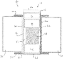
- FIG. 17 represents a sensor assembly 40 comprising the sensing device 10 of FIG. 11 assembled with the anchor 50 of FIG. 5 , and shows the sensor assembly 40 implanted in a wall 30 of an organ with the anchor 50 .
- the distal and proximal ends 24 and 26 of the sensing device 10 are located at or adjacent opposite ends of the through-hole 62 of the anchor 50 , which surrounds or circumscribes the housing 12 between its distal and proximal ends 24 and 26 .
- the internal antenna 18 located at the midsection of the housing 12 ) is not surrounded by either ring 58 and 60 of the anchor 50 , but instead is only surrounded or circumscribed by the longitudinal legs 66 that interconnect the rings 58 and 60 .
- FIG. 18 represents a sensor assembly 40 comprising the anchor 50 of FIG. 5 similar to FIG. 17 , but assembled with the sensing device 10 of FIG. 7 .
- the distal and proximal ends 24 and 26 of the sensing device 10 are again located at opposite ends of the through-hole 62 of the anchor 50 , and the internal antenna 18 (located near the proximal end 26 of the housing 12 ) is only surrounded or circumscribed by the longitudinal legs 66 and is not surrounded by either ring 58 or 60 .
- FIG. 19 represents a sensor assembly 40 in which the sensing device 10 of FIG. 7 assembled with a modified version of the anchor 50 of FIG. 5 , in which the longitudinal legs 66 axially extend and protrude beyond both rings 58 and 60 of the anchor 50 .
- the internal antenna 18 (located at the midsection of the housing 12 ) is predominantly (though not exclusively) surrounded or circumscribed by the longitudinal legs 66 that interconnect rings of the anchor 50 .
- the rings 58 and 60 may be metallic, the legs 66 are preferably formed of a nonmetallic material so as to not have a Faraday-cage effect on the antenna 18 .
- FIG. 20 represents a sensor assembly 40 comprising the sensing device 10 of FIG. 10 assembled with the anchor 50 of FIG. 2 , and shows the sensor assembly 40 implanted in a wall 30 of an organ with the anchor 50 .
- the distal and proximal ends 24 and 26 of the sensing device 10 are located outside of the through-hole 62 of the anchor 50 , which contacts and surrounds or circumscribes the region of the housing 12 formed by the additional housing portion 20 or otherwise in which the additional housing portion 20 is present and predominant.
- the external antenna 18 of the sensing device 10 is not surrounded or circumscribed by any portion of the anchor 50 .
- FIGS. 21 and 22 schematically represent additional embodiments of sensing devices 10 that comprise an additional housing portion 20 that is separately formed and directly attached to the distal end 24 of the sensing device housing 12 ( FIG. 21 ) or integrally formed as a discrete region at the distal end 24 of the housing 12 ( FIG. 22 ), but are otherwise similar in many respects to the sensing devices 10 discussed above.
- the housings 12 of the sensing devices 10 are sized and shaped to accommodate the transducer 14 , electronic circuitry 16 , and antenna 18 within its internal cavity (or cavities) 22 .
- the 21 and 22 include a housing portion 20 that is in addition to the internal cavity (or cavities) 22 that contain(s) the transducer 14 , electronic circuitry 16 , and antenna 18 .
- the aforementioned housing portions 20 are sized and shaped for direct attachment to an anchor 50 or to an anchor interface member 70 ( FIG. 23, 25 , or 27 ) through which an anchor 50 can be coupled to the sensing devices 10 ( FIGS. 24 and 26 ).
- the housing portions 20 of FIGS. 21 and 22 are not required to contain any component relating to the operation of the sensing device 10 or its transducer 14 , electronic circuitry 16 , or antenna 18 , and therefore a cavity is not required to be present in the additional housing portions 20 .
- the representations of the additional housing portions 20 in the drawings do not necessarily (though may) indicate a cavity, but instead more generally indicate a cavity-free solid.
- the housing portions 20 of FIGS. 21 and 22 are shown as extending from ( FIG. 21 ) or defining ( FIG. 22 ) the distal end 24 of their respective housings 12 and adjacent distal cavity regions 22 A within the cavities 22 that do not contain any component relating to the operation of the sensing device 10 or its transducer 14 , electronic circuitry 16 , or antenna 18 .
- the housing portions 20 may be viewed as further encompassing the portion of their corresponding housing 12 in which the distal cavity regions 22 A are located, though in the following discussion the housing portions 20 will be discussed as discrete portions of their respective sensing devices 10 .
- the housing portion 20 represented in FIG. 21 is a separately formed body that is then attached to the distal end 24 of the sensing device housing 12 by any suitable means, for example, an adhesive, fastener, metallurgical joint, mechanical clamping, thermal compression, etc., or combinations thereof.
- the housing portion 20 is configured to define an annular groove 72 surrounding a reduced portion 74 of the housing portion 20 .
- the groove 72 and reduced portion 74 separate the distal end 24 of the housing 12 form an enlarged knob 76 , which defines a proximal shoulder 78 facing the proximal end 26 of the housing 12 .
- the groove 72 , knob 76 , and/or shoulder 78 provide coupling means (physical features) by which an anchor 50 or anchor interface member 70 may be coupled to the sensing device 10 .
- the knob 76 may have various different shapes and cross-sectional shapes, including but not limited to spherical, disk, oval, rectangular, cubic, meander, wire, or combinations thereof.
- the diameter or lateral dimension of the knob 76 is shown as equal to that at the distal end 24 of the housing 12 , though other diameters or lateral dimensions may be acceptable, depending on the particular anchor 50 or anchor interface member 70 to be coupled.
- the housing portion 20 represented in FIG. 22 is integrally formed as a discrete region of the housing 12 at its distal end 24 .
- the housing portion 20 of FIG. 22 may (see phantom lines) but is not required to define an annular groove, and defines an enlarged knob 76 that defines a proximal shoulder 78 facing the proximal end 26 of the housing 12 .
- the diameter or lateral dimension of the knob 76 is shown as greater than that of the housing 12 at its distal end 24 , thereby providing coupling means (physical feature) by which an anchor 50 or anchor interface member 70 may be coupled to the sensing device 10 .
- the housing portions 20 represented in FIGS. 21 and 22 define knobs 76 and shoulders 78 and optional grooves 72 by which an anchor 50 or anchor interface member 70 may be coupled, though additional features are also foreseeable, for example, recesses, meander shapes or grooves, fastening features (e.g., threads), additional grooves, etc.
- the cross-sectional shapes of the housing portions 20 may be round, though other shapes are also foreseeable.
- FIGS. 23 through 27 represent the sensing device 10 of FIG. 21 coupled to various anchors 50 and anchor interface members 70 through its housing portion 20 . It should be understood that the sensing device 10 of FIG. 22 could be similarly coupled to the anchors 50 and interface members 70 through its housing portion 20 .
- the anchors 50 and interface members 70 may be formed or fabricated from a variety of materials, including but not limited to metals including stainless steels and shape-memory alloys (e.g., NiTi alloys), polymers including PEEK, or combinations thereof.
- the housing portion 20 of the device 10 is coupled to an interface member 70 , which in turn serves to couple an anchor 50 to the device 10 to yield a sensor assembly 40 .
- the interface member 70 comprises a head 80 having a cavity, recess, or groove 82 adapted to surround and grip the knob 76 of the housing portion 20 .
- the interface member 70 further comprises a stem or post 84 that extends away from the device housing 12 along the longitudinal axis 28 of the housing 12 .
- the post 84 is represented as having a continuous cross-sectional shape and size, and the anchor 50 is shown in FIG.
- FIGS. 25, 26, and 27 depict embodiments that differ from that of FIGS. 23 and 24 by the inclusion of a knob 86 on the end of the post 84 of the interface member 70 .
- the knob 86 has a larger cross-sectional shape than the post 84 to further facilitate the attachment of the anchor 50 and promote its retention on the sensing device 10 .
- the knobs 86 are depicted in FIGS.
- the anchor 50 or interface device 70 may be configured as a means for attaching and releasing the sensing device 10 with a delivery catheter.
- the anchor 50 may be, but is not limited to, anchors of types used as vascular closure devices, atrial septum defect occluder devices (ASD and PFO occluders), closure paravalvular leak devices, and other types of anchors.
- the housing portions 20 depicted in FIGS. 21 through 27 are particularly well suited for enabling a sensing device 10 to be secured with an anchor 50 such that the transducer 14 and antenna 18 of the sensing device 10 are sufficiently remote from the anchor 50 and anchor interface member 70 that any metallic portions thereof surround at least a portion of the housing portion 20 but do not surround the transducer 14 or antenna 18 and do not interfere with their operations.
- the anchor 50 is configured as a vascular closure device, atrial septum defect occluder device (ASD or PFO occluder), or closure paravalvular leak device
- the assembly 40 can be used as a closure or occluder device in addition to sensing a physiological parameter of a living being.
- a notable advantage of sensor assemblies 40 of the types described above include the capability of effective long-term monitoring of the cardiovascular system and organs.
- Data obtained with the sensing devices 10 can be used for multiple purposes, including but limited to management of cardiac diseases, such as congestive heart failure, arrhythmia, structural heart diseases, congenital heart diseases, patients with single functioning ventricle, hypotension, hypertension, etc., and long-term management of patients.
- Data from the sensing devices 10 may be sampled at home, at a doctor's office, in a surgery room, during post-op stay including ICU, and during hospital stay.
- Sensor assemblies 40 of the types represented in FIGS. 12 through 20, 24, and 26 can be implanted in various ways.
- one of the assemblies may be implanted in the wall 30 of the organ so that the proximal end 26 of the sensor housing 12 slightly protrudes into the organ, with the result that the sensor assembly 40 has little or no effect on blood flow through the organ.
- the entire sensor assembly 40 may be placed inside an organ, in which case an anchor 50 may be used to secure the sensing device 10 so that it is centrally located within the organ but is spaced apart from the walls 30 of the organ by legs or arms of the anchor 50 so as to have little if any effect on blood flow.
- the anchor 50 can be equipped with one or more loops, fingers, spirals, screws, etc., that secure the sensing device 10 to oppositely-disposed walls 30 of the organ.
- the anchor 50 may be stitched to the wall 30 of the organ, such as with an anchor 50 disclosed in U.S. Pat. No. 9,168,005
- sensing devices and sensing assemblies of the types described above can be accomplished by percutaneous delivery, catheter delivery (preferably through the femoral vein), minimally invasive approaches, surgical approaches, or combinations thereof.
- the delivery procedure may be a standalone procedure or performed as part of another procedure.
- the sensing devices 10 , anchors 50 , and sensor assemblies could differ in appearance and construction from the embodiments described herein and shown in the drawings, functions of certain components of the sensing devices 10 , anchors 50 , and sensor assemblies could be performed by components of different construction but capable of a similar (though not necessarily equivalent) function, and appropriate materials could be substituted for those noted.
- the invention encompasses additional or alternative embodiments in which one or more features or aspects of different disclosed embodiments may be combined. Accordingly, it should be understood that the invention is not necessarily limited to any embodiment described herein or illustrated in the drawings. It should also be understood that the phraseology and terminology employed above are for the purpose of describing the illustrated embodiments, and do not necessarily serve as limitations to the scope of the invention. Therefore, the scope of the invention is to be limited only by the following claims.
Landscapes
- Health & Medical Sciences (AREA)
- Life Sciences & Earth Sciences (AREA)
- Engineering & Computer Science (AREA)
- Surgery (AREA)
- General Health & Medical Sciences (AREA)
- Biophysics (AREA)
- Biomedical Technology (AREA)
- Heart & Thoracic Surgery (AREA)
- Medical Informatics (AREA)
- Molecular Biology (AREA)
- Physics & Mathematics (AREA)
- Animal Behavior & Ethology (AREA)
- Pathology (AREA)
- Public Health (AREA)
- Veterinary Medicine (AREA)
- Cardiology (AREA)
- Vascular Medicine (AREA)
- Physiology (AREA)
- Computer Networks & Wireless Communication (AREA)
- Measuring And Recording Apparatus For Diagnosis (AREA)
Abstract
Description
Claims (11)
Priority Applications (2)
| Application Number | Priority Date | Filing Date | Title |
|---|---|---|---|
| US15/805,969 US10687709B2 (en) | 2016-05-09 | 2017-11-07 | Implantable sensing devices and anchoring methods therefor |
| EP17210340.0A EP3479757B1 (en) | 2017-11-07 | 2017-12-22 | Implantable sensing devices and anchoring methods therefor |
Applications Claiming Priority (5)
| Application Number | Priority Date | Filing Date | Title |
|---|---|---|---|
| US201662391743P | 2016-05-09 | 2016-05-09 | |
| US201662391742P | 2016-05-09 | 2016-05-09 | |
| US15/591,087 US10478067B2 (en) | 2016-05-09 | 2017-05-09 | Implantable sensing devices and anchoring methods therefor |
| US201762604516P | 2017-07-10 | 2017-07-10 | |
| US15/805,969 US10687709B2 (en) | 2016-05-09 | 2017-11-07 | Implantable sensing devices and anchoring methods therefor |
Related Parent Applications (1)
| Application Number | Title | Priority Date | Filing Date |
|---|---|---|---|
| US15/591,087 Continuation-In-Part US10478067B2 (en) | 2016-05-09 | 2017-05-09 | Implantable sensing devices and anchoring methods therefor |
Publications (2)
| Publication Number | Publication Date |
|---|---|
| US20180116516A1 US20180116516A1 (en) | 2018-05-03 |
| US10687709B2 true US10687709B2 (en) | 2020-06-23 |
Family
ID=62020699
Family Applications (1)
| Application Number | Title | Priority Date | Filing Date |
|---|---|---|---|
| US15/805,969 Active 2037-11-30 US10687709B2 (en) | 2016-05-09 | 2017-11-07 | Implantable sensing devices and anchoring methods therefor |
Country Status (1)
| Country | Link |
|---|---|
| US (1) | US10687709B2 (en) |
Cited By (6)
| Publication number | Priority date | Publication date | Assignee | Title |
|---|---|---|---|---|
| US11461568B2 (en) | 2017-02-24 | 2022-10-04 | Endotronix, Inc. | Wireless sensor reader assembly |
| US11589773B2 (en) | 2011-06-30 | 2023-02-28 | Endotronix, Inc. | MEMS device for an implant assembly |
| US11615257B2 (en) | 2017-02-24 | 2023-03-28 | Endotronix, Inc. | Method for communicating with implant devices |
| US11622684B2 (en) | 2017-07-19 | 2023-04-11 | Endotronix, Inc. | Physiological monitoring system |
| US11707230B2 (en) | 2011-06-30 | 2023-07-25 | Endotronix, Inc. | Pressure sensing implant |
| US11896365B2 (en) | 2011-06-30 | 2024-02-13 | Endotronix, Inc. | MEMS device for an implant assembly |
Families Citing this family (4)
| Publication number | Priority date | Publication date | Assignee | Title |
|---|---|---|---|---|
| WO2021040726A1 (en) * | 2019-08-29 | 2021-03-04 | Integrated Sensing Systems, Incorporated | Anchors and anchoring methods for implantable devices |
| US11504003B2 (en) | 2019-08-29 | 2022-11-22 | Uim Pressure Implant Inc. | Anchors and anchoring methods for implantable devices |
| JP7711326B2 (en) * | 2021-08-27 | 2025-07-22 | ダブリュ.エル.ゴア アンド アソシエイツ,インコーポレイティド | Implantable medical devices and wireless sensor attachments |
| AU2022332190B2 (en) * | 2021-08-27 | 2025-06-26 | Uim Pressure Implant Inc. | Anchors and wireless sensor attachment |
Citations (7)
| Publication number | Priority date | Publication date | Assignee | Title |
|---|---|---|---|---|
| EP0989384A2 (en) | 1998-09-24 | 2000-03-29 | Biosense, Inc. | Miniaturized position sensor |
| US20020077555A1 (en) | 2000-12-18 | 2002-06-20 | Yitzhack Schwartz | Method for anchoring a medical device between tissue |
| US20020120200A1 (en) | 1997-10-14 | 2002-08-29 | Brian Brockway | Devices, systems and methods for endocardial pressure measurement |
| US20060187044A1 (en) | 2005-02-10 | 2006-08-24 | Carl E.Fabian | Surgical implement detector |
| US20090005656A1 (en) * | 2007-06-28 | 2009-01-01 | Integrated Sensing Systems, Inc. | Minimally-invasive procedure for monitoring a physiological parameter within an internal organ |
| US20130144379A1 (en) * | 2011-06-08 | 2013-06-06 | Integrated Sensing Systems, Inc. | Implantable wireless sensor systems |
| WO2016131020A1 (en) | 2015-02-12 | 2016-08-18 | Foundry Innovation & Research 1, Ltd. | Implantable devices and related methods for heart failure monitoring |
-
2017
- 2017-11-07 US US15/805,969 patent/US10687709B2/en active Active
Patent Citations (7)
| Publication number | Priority date | Publication date | Assignee | Title |
|---|---|---|---|---|
| US20020120200A1 (en) | 1997-10-14 | 2002-08-29 | Brian Brockway | Devices, systems and methods for endocardial pressure measurement |
| EP0989384A2 (en) | 1998-09-24 | 2000-03-29 | Biosense, Inc. | Miniaturized position sensor |
| US20020077555A1 (en) | 2000-12-18 | 2002-06-20 | Yitzhack Schwartz | Method for anchoring a medical device between tissue |
| US20060187044A1 (en) | 2005-02-10 | 2006-08-24 | Carl E.Fabian | Surgical implement detector |
| US20090005656A1 (en) * | 2007-06-28 | 2009-01-01 | Integrated Sensing Systems, Inc. | Minimally-invasive procedure for monitoring a physiological parameter within an internal organ |
| US20130144379A1 (en) * | 2011-06-08 | 2013-06-06 | Integrated Sensing Systems, Inc. | Implantable wireless sensor systems |
| WO2016131020A1 (en) | 2015-02-12 | 2016-08-18 | Foundry Innovation & Research 1, Ltd. | Implantable devices and related methods for heart failure monitoring |
Non-Patent Citations (1)
| Title |
|---|
| European Search Report for European Application No. 17210340.0, dated Jan. 21, 2019, 16 pages. |
Cited By (9)
| Publication number | Priority date | Publication date | Assignee | Title |
|---|---|---|---|---|
| US11589773B2 (en) | 2011-06-30 | 2023-02-28 | Endotronix, Inc. | MEMS device for an implant assembly |
| US11707230B2 (en) | 2011-06-30 | 2023-07-25 | Endotronix, Inc. | Pressure sensing implant |
| US11896365B2 (en) | 2011-06-30 | 2024-02-13 | Endotronix, Inc. | MEMS device for an implant assembly |
| US12201414B2 (en) | 2011-06-30 | 2025-01-21 | Endotronix, Inc. | Pressure sensing implant |
| US12507907B2 (en) | 2011-06-30 | 2025-12-30 | Endotronix, Inc. | MEMS device for an implant assembly |
| US11461568B2 (en) | 2017-02-24 | 2022-10-04 | Endotronix, Inc. | Wireless sensor reader assembly |
| US11615257B2 (en) | 2017-02-24 | 2023-03-28 | Endotronix, Inc. | Method for communicating with implant devices |
| US11622684B2 (en) | 2017-07-19 | 2023-04-11 | Endotronix, Inc. | Physiological monitoring system |
| US12213760B2 (en) | 2017-07-19 | 2025-02-04 | Endotronix, Inc. | Physiological monitoring system |
Also Published As
| Publication number | Publication date |
|---|---|
| US20180116516A1 (en) | 2018-05-03 |
Similar Documents
| Publication | Publication Date | Title |
|---|---|---|
| US10687709B2 (en) | Implantable sensing devices and anchoring methods therefor | |
| US10478067B2 (en) | Implantable sensing devices and anchoring methods therefor | |
| EP3843618B1 (en) | Anchors for implantable devices | |
| US11504003B2 (en) | Anchors and anchoring methods for implantable devices | |
| US20230218232A1 (en) | Cardiac implant devices with integrated pressure sensing | |
| US8322346B2 (en) | Minimally-invasive procedure for monitoring a physiological parameter within an internal organ | |
| US8267863B2 (en) | Procedure and system for monitoring a physiological parameter within an internal organ of a living body | |
| US9498130B2 (en) | Wireless device and system for monitoring physiologic parameters | |
| US10383575B2 (en) | Minimally-invasive procedures for monitoring physiological parameters within internal organs and anchors therefor | |
| US20130085350A1 (en) | Antenna structures for implantable medical devices | |
| US20150157268A1 (en) | Organ wall retention mechanism for implants | |
| WO2012090206A2 (en) | Method and systems for delivering and deploying a sensory implant in situ | |
| US20080312712A1 (en) | Implantable Devices and Methods for Stimulation of Cardiac or Other Tissues | |
| US20120296222A1 (en) | Implantable Medical Sensor and Anchoring System | |
| US20120291788A1 (en) | Implantable Medical Sensor and Anchoring System | |
| US10835133B2 (en) | Hydrostatic offset adjustment for measured cardiovascular pressure values | |
| US9241638B2 (en) | System and method for implanting a physiologic sensor assembly | |
| TW202304548A (en) | Implant-coupled sensors | |
| WO2018213548A1 (en) | Antenna for implantable medical devices | |
| EP3479757B1 (en) | Implantable sensing devices and anchoring methods therefor | |
| US20230172552A1 (en) | Cardiovascular monitoring system | |
| US20160183842A1 (en) | Minimally-invasive procedures for monitoring physiological parameters within internal organs and anchors therefor | |
| US20230277856A1 (en) | An intraluminal contraction augmentation system | |
| TW202304549A (en) | Sensor implant device anchoring |
Legal Events
| Date | Code | Title | Description |
|---|---|---|---|
| FEPP | Fee payment procedure |
Free format text: ENTITY STATUS SET TO UNDISCOUNTED (ORIGINAL EVENT CODE: BIG.); ENTITY STATUS OF PATENT OWNER: SMALL ENTITY |
|
| FEPP | Fee payment procedure |
Free format text: ENTITY STATUS SET TO SMALL (ORIGINAL EVENT CODE: SMAL); ENTITY STATUS OF PATENT OWNER: SMALL ENTITY |
|
| AS | Assignment |
Owner name: INTEGRATED SENSING SYSTEMS, INC., MICHIGAN Free format text: ASSIGNMENT OF ASSIGNORS INTEREST;ASSIGNOR:NAJAFI, NADER;REEL/FRAME:044641/0458 Effective date: 20171113 |
|
| STPP | Information on status: patent application and granting procedure in general |
Free format text: DOCKETED NEW CASE - READY FOR EXAMINATION |
|
| STPP | Information on status: patent application and granting procedure in general |
Free format text: NON FINAL ACTION MAILED |
|
| STPP | Information on status: patent application and granting procedure in general |
Free format text: RESPONSE TO NON-FINAL OFFICE ACTION ENTERED AND FORWARDED TO EXAMINER |
|
| STPP | Information on status: patent application and granting procedure in general |
Free format text: NOTICE OF ALLOWANCE MAILED -- APPLICATION RECEIVED IN OFFICE OF PUBLICATIONS |
|
| STPP | Information on status: patent application and granting procedure in general |
Free format text: PUBLICATIONS -- ISSUE FEE PAYMENT VERIFIED |
|
| STCF | Information on status: patent grant |
Free format text: PATENTED CASE |
|
| AS | Assignment |
Owner name: UIM PRESSURE IMPLANT INC., MICHIGAN Free format text: ASSIGNMENT OF ASSIGNORS INTEREST;ASSIGNOR:INTEGRATED SENSING SYSTEMS INCORPORATED;REEL/FRAME:061220/0908 Effective date: 20220818 |
|
| MAFP | Maintenance fee payment |
Free format text: PAYMENT OF MAINTENANCE FEE, 4TH YR, SMALL ENTITY (ORIGINAL EVENT CODE: M2551); ENTITY STATUS OF PATENT OWNER: SMALL ENTITY Year of fee payment: 4 |