US10682879B2 - Mirrored fluorescent security feature - Google Patents
Mirrored fluorescent security feature Download PDFInfo
- Publication number
- US10682879B2 US10682879B2 US15/766,537 US201615766537A US10682879B2 US 10682879 B2 US10682879 B2 US 10682879B2 US 201615766537 A US201615766537 A US 201615766537A US 10682879 B2 US10682879 B2 US 10682879B2
- Authority
- US
- United States
- Prior art keywords
- photo
- mirror element
- secure document
- transparent window
- luminescent feature
- Prior art date
- Legal status (The legal status is an assumption and is not a legal conclusion. Google has not performed a legal analysis and makes no representation as to the accuracy of the status listed.)
- Active
Links
Images


Classifications
-
- B—PERFORMING OPERATIONS; TRANSPORTING
- B42—BOOKBINDING; ALBUMS; FILES; SPECIAL PRINTED MATTER
- B42D—BOOKS; BOOK COVERS; LOOSE LEAVES; PRINTED MATTER CHARACTERISED BY IDENTIFICATION OR SECURITY FEATURES; PRINTED MATTER OF SPECIAL FORMAT OR STYLE NOT OTHERWISE PROVIDED FOR; DEVICES FOR USE THEREWITH AND NOT OTHERWISE PROVIDED FOR; MOVABLE-STRIP WRITING OR READING APPARATUS
- B42D25/00—Information-bearing cards or sheet-like structures characterised by identification or security features; Manufacture thereof
- B42D25/30—Identification or security features, e.g. for preventing forgery
- B42D25/351—Translucent or partly translucent parts, e.g. windows
-
- B—PERFORMING OPERATIONS; TRANSPORTING
- B41—PRINTING; LINING MACHINES; TYPEWRITERS; STAMPS
- B41M—PRINTING, DUPLICATING, MARKING, OR COPYING PROCESSES; COLOUR PRINTING
- B41M3/00—Printing processes to produce particular kinds of printed work, e.g. patterns
- B41M3/14—Security printing
- B41M3/144—Security printing using fluorescent, luminescent or iridescent effects
-
- B—PERFORMING OPERATIONS; TRANSPORTING
- B42—BOOKBINDING; ALBUMS; FILES; SPECIAL PRINTED MATTER
- B42D—BOOKS; BOOK COVERS; LOOSE LEAVES; PRINTED MATTER CHARACTERISED BY IDENTIFICATION OR SECURITY FEATURES; PRINTED MATTER OF SPECIAL FORMAT OR STYLE NOT OTHERWISE PROVIDED FOR; DEVICES FOR USE THEREWITH AND NOT OTHERWISE PROVIDED FOR; MOVABLE-STRIP WRITING OR READING APPARATUS
- B42D25/00—Information-bearing cards or sheet-like structures characterised by identification or security features; Manufacture thereof
- B42D25/30—Identification or security features, e.g. for preventing forgery
- B42D25/328—Diffraction gratings; Holograms
-
- B—PERFORMING OPERATIONS; TRANSPORTING
- B42—BOOKBINDING; ALBUMS; FILES; SPECIAL PRINTED MATTER
- B42D—BOOKS; BOOK COVERS; LOOSE LEAVES; PRINTED MATTER CHARACTERISED BY IDENTIFICATION OR SECURITY FEATURES; PRINTED MATTER OF SPECIAL FORMAT OR STYLE NOT OTHERWISE PROVIDED FOR; DEVICES FOR USE THEREWITH AND NOT OTHERWISE PROVIDED FOR; MOVABLE-STRIP WRITING OR READING APPARATUS
- B42D25/00—Information-bearing cards or sheet-like structures characterised by identification or security features; Manufacture thereof
- B42D25/30—Identification or security features, e.g. for preventing forgery
- B42D25/36—Identification or security features, e.g. for preventing forgery comprising special materials
- B42D25/373—Metallic materials
-
- B—PERFORMING OPERATIONS; TRANSPORTING
- B42—BOOKBINDING; ALBUMS; FILES; SPECIAL PRINTED MATTER
- B42D—BOOKS; BOOK COVERS; LOOSE LEAVES; PRINTED MATTER CHARACTERISED BY IDENTIFICATION OR SECURITY FEATURES; PRINTED MATTER OF SPECIAL FORMAT OR STYLE NOT OTHERWISE PROVIDED FOR; DEVICES FOR USE THEREWITH AND NOT OTHERWISE PROVIDED FOR; MOVABLE-STRIP WRITING OR READING APPARATUS
- B42D25/00—Information-bearing cards or sheet-like structures characterised by identification or security features; Manufacture thereof
- B42D25/30—Identification or security features, e.g. for preventing forgery
- B42D25/36—Identification or security features, e.g. for preventing forgery comprising special materials
- B42D25/378—Special inks
- B42D25/382—Special inks absorbing or reflecting infrared light
-
- B—PERFORMING OPERATIONS; TRANSPORTING
- B42—BOOKBINDING; ALBUMS; FILES; SPECIAL PRINTED MATTER
- B42D—BOOKS; BOOK COVERS; LOOSE LEAVES; PRINTED MATTER CHARACTERISED BY IDENTIFICATION OR SECURITY FEATURES; PRINTED MATTER OF SPECIAL FORMAT OR STYLE NOT OTHERWISE PROVIDED FOR; DEVICES FOR USE THEREWITH AND NOT OTHERWISE PROVIDED FOR; MOVABLE-STRIP WRITING OR READING APPARATUS
- B42D25/00—Information-bearing cards or sheet-like structures characterised by identification or security features; Manufacture thereof
- B42D25/30—Identification or security features, e.g. for preventing forgery
- B42D25/36—Identification or security features, e.g. for preventing forgery comprising special materials
- B42D25/378—Special inks
- B42D25/387—Special inks absorbing or reflecting ultraviolet light
Definitions
- the present disclosure is generally directed toward security features and methods of incorporating security features into documents, credentials, passports, and other substrates.
- Credentials are used on a daily basis for a number of different purposes. Credentials are most commonly used to prove identity, to verify age, to access an asset (e.g., secure area, financial account, computing resource, etc.), to evidence driving privileges, to cash a check, and so on. Airplane passengers are required to show a credential during check in, and sometimes at security screening and prior to boarding their flight. We also live in an ever-evolving cashless society where credentials are used to make payments, access an automated teller machine (ATM), debit an account, or make a payment, etc. Many industries require that their employees carry photo identification credentials on the job and to access various locations on a job site.
- ATM automated teller machine
- Prior art credentials 100 include a laminated structure 104 having a windowed security feature 112 whose boundaries/edges are defined by one or more opaque portions 108 included in the laminated structure 104 .
- Such known prior art credentials 100 include a photo-luminescent feature 116 within a viewing area of the windowed security feature 112 .
- prior art credentials 100 are known to include printed features 120 and other additional images 124 within the laminated structure 104 .
- the luminescence of the photo-luminescent feature 116 in the windowed security feature 112 is not optimal and the visibility of the photo-luminescent feature 116 when illuminated with light of a particular wavelength is not sufficient unless controlled lighting conditions exist (e.g., minimal surrounding/ambient light) for the person viewing the credential 100 . This makes the overall utility of the windowed security feature 112 less desirable and utilized.
- a credential or document having a windowed security feature that includes at least one photo-luminescent feature (e.g., Ultraviolet (UV) fluorescent ink or Infrared (IR) photo-luminescent ink) and at least one mirror element that are viewable through the viewing area of the windowed security feature.
- photo-luminescent feature e.g., Ultraviolet (UV) fluorescent ink or Infrared (IR) photo-luminescent ink
- IR Infrared
- one embodiment of such a credential comprises:
- a first photo-luminescent feature positioned relative to the transparent window and the mirror element such that the mirror element enhances a luminescence of the first photo-luminescent feature when viewed and illuminated through the transparent window.
- the first photo-luminescent material is positioned in a view area of the transparent window.
- the credential further includes a second photo-luminescent material that is different from the photo-luminescent material.
- the mirror element is situated between the first photo-luminescent material and the second photo-luminescent material.
- the first photo-luminescent material is visible through the transparent window when viewed from a first direction and the second photo-luminescent material is visible through the transparent window when viewed from a second direction that is different from the first direction.
- the mirror element comprises a printed mirror.
- the mirror element comprises at least one of metallic flakes or retro reflective beads.
- the mirror element comprises an antenna.
- the mirror element comprises a foil mirror.
- the mirror element comprises a diffractive element.
- the first photo-luminescent material comprises an ultraviolet visible ink.
- the transparent window corresponds to an opening in an opaque layer of the secure document and the opening in the opaque layer aligns with the first photo-luminescent material and the mirror element.
- the mirror element includes a predetermined shape that is visible through the transparent window when the first photo-luminescent material is illuminated with light of a predetermined wavelength.
- the mirror element is provided on a separate layer of the secure document than the first photo-luminescent material.
- FIG. 1 is a cross-sectional view of a prior art security credential
- FIG. 2 is a cross-sectional view of a security document or credential according to aspects of the present disclosure
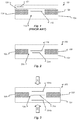
- FIG. 3 is a cross-sectional view of a second credential according to aspects of the present disclosure.
- FIG. 4A is an image of the credential of FIG. 3 , taken in the direction D 1 , showing the intensity of off-white UV ink for the photo-luminescent feature 304 a;
- FIG. 4B is an image of the credential of FIG. 3 , taken in the direction D 2 , showing the intensity of red UV ink for the photo-luminescent feature 304 b;
- FIG. 5 is an exploded view illustrating the layers of a credential made according to aspects of the present disclosure
- FIG. 6A is a first pair of images A 1 and A 2 of a credential according to aspects of the present disclosure where the credential includes a separation of 150 microns between the UV layer and the mirror element, as depicted in the exploded view of the credential below images A 1 and A 2 ;
- FIG. 6B is a second pair of images B 1 and B 2 of a credential according to aspects of the present disclosure where the credential includes a separation of 450 microns between the UV layer and the mirror element, as depicted in the exploded view of the credential below images B 1 and B 2 ;
- FIG. 7 is an image of a credential according to aspects of the present disclosure where the credential includes a separation of 500 microns between the mirror element and the outer surface of the credential.
- the credential 200 is shown to include a laminated structure 104 , which can include two or more layers of material that have been laminated together through one or more lamination processes.
- the laminated structure 104 includes one or more optically opaque portions 108 that are substantially opaque to light of a wavelength of interest of a band of wavelengths.
- the opaque portions 108 may be substantially non-transparent to visible light, UV light, IR light, and other forms of light around the visible light spectrum.
- a break or interruption in the opaque portions 108 creates a windowed feature 208 that enables a person or machine to view light of a wavelength of interest passing through the windowed security feature 208 .
- the improved windowed security feature 208 includes a mirror element 204 that is substantially proximal or adjacent to a photo-luminescent feature 116 .
- the mirror element 204 and photo-luminescent feature 116 are both contained within a viewing area or viewing window defined for the windowed security feature 208 .
- a person or machine may view the photo-luminescent feature 116 and/or the mirror element 204 through the window of the windowed security feature 208 .
- luminescence of the photo-luminescent feature 116 through the window 208 is improved/enhanced by the mirror element 204 .
- the luminescence of the photo-luminescent feature 116 is greatly improved/enhanced due to the mirror element 204 reflecting light passing through the window 208 back toward the photo-luminescent feature 116 .
- the photo-luminescent feature 116 is illuminated with light that directly impacts the photo-luminescent feature 116 as well as light that passes by or through the photo-luminescent feature 116 , and is reflected off the mirror element 208 .
- This extra illumination by virtue of reflecting light back onto the photo-luminescent feature 116 helps to make the photo-luminescent feature 116 much more visible to an inspecting person or machine.
- the mirror element 204 and photo-luminescent feature 116 may both be positioned within the boundaries of the window feature 208 and, in particular, may be positioned within the laminate structure 104 such that both the photo-luminescent feature 116 and mirror element 204 do not extend above or below the opaque portions 108 of the laminated structure 104 .
- FIG. 3 shows an embodiment of the present disclosure where there are two photo-luminescent features 304 a , 304 b provided in the laminated structure 104 and which are visible via the windowed security feature 208 .
- the credential 300 of FIG. 3 includes a first photo-luminescent feature 304 a and a second photo-luminescent feature 304 b with a mirror element 204 sandwiched between the two.
- the mirror element 204 is shown to be positioned entirely within the opening of the opaque portions 108 that creates the window feature 208 whereas the photo-luminescent features 304 a , 304 b are positioned vertically within the window feature 208 but horizontally out of plane of the opening of the opaque portions 108 .
- the photo-luminescent features 304 a , 304 b may be viewed from either a first viewing direction D 1 or a second viewing direction D 2 by a person or machine even though the photo-luminescent features 304 a , 304 b are not horizontally positioned within the opening of the opaque portions 108 .
- the viewing window of the windowed security feature 208 is created by one or more cutouts, absences, vias, or openings in the opaque portions 108 when the opaque portions are laminated with other layers to create the laminated structure 104 .
- the particular placement of the features 204 , 304 a , 304 b may vary without departing from the scope of the present disclosure.
- the area covered by the photo-luminescent features 304 a , 304 b may be greater than the area covered by the mirror element 204 (although the reverse situation may also be employed without departing from the scope of the present disclosure).
- one or both of the photo-luminescent features 304 a , 304 b may extend through the entirety of a layer in the laminated structure 104 .
- the photo-luminescent features 304 a , 304 b may extend just beyond the opening of the window security feature 208 .
- Using the credential 300 of FIG. 3 as compared to the credential 200 of FIG. 2 may provide some additional benefits.
- viewing the credential 300 from a first viewing direction D 1 may result in a first viewing experience whereas viewing the credential 300 from a second viewing direction D 2 may result in a second viewing experience different from the first viewing experience.
- the mirror element 204 when illuminated with light and when viewed from the first viewing direction D 1 , the mirror element 204 may substantially block light from impacting the second photo-luminescent feature 304 b , which means that the luminescence of the first photo-luminescent feature 304 a may be enhanced and be the primary visible feature.
- the mirror element 204 may substantially block light coming from the second viewing direction D 2 from impacting the first photo-luminescent feature 304 a . This may result in a viewing experience from the second viewing direction D 2 where the second photo-luminescent feature 304 b has its luminescence enhanced whereas the first photo-luminescent feature 304 a is not visible through the window 208 .
- the viewing experience for the credential 200 of FIG. 2 may be different from the viewing experience of the credential 300 .
- the viewing experience from the top of the credential 200 may result in an improved luminescence for the photo-luminescent feature 116 whereas the viewing experience from the bottom of the credential 200 (e.g., where illuminated light and a viewing party) will first see the mirror element 204 instead of the photo-luminescent feature 116 , which may actually block visibility of the photo-luminescent feature 116 .
- the photo-luminescent features 116 , 304 a , 304 b may correspond to photo-luminescent or photo-reactive inks that are printed on one or more layers of the laminated structure 104 .
- the inks may be UV fluorescent inks, IR fluorescent inks, or any other type of photo-reactive compound known in the art.
- the photo-luminescent features 304 a , 304 b may be the same as one another or different from one another.
- the first photo-luminescent feature 304 a may correspond to UV fluorescent ink of a first color (e.g., red UV ink) whereas the second photo-luminescent feature 304 b may correspond to a UV fluorescent ink of a second color (e.g., white UV ink).
- a first color e.g., red UV ink
- the second photo-luminescent feature 304 b may correspond to a UV fluorescent ink of a second color (e.g., white UV ink).
- the use of two different invisible UV-fluorescent inks for the features 304 a , 304 b , printed by offset lithography in different layers of the laminated structure 104 enables two different color emissions when the window is examined from the two different sides of the credential 300 (e.g., from the different viewing directions D 1 , D 2 ).
- This effect is made much stronger when a mirror element 204 is provided (e.g., printed, stamped, etc.) between the two fluorescent printings.
- This mirror element 204 acts in 2 ways: (1) to boost the fluorescence from the print on the side being observed and (2) to block the fluorescence from the print on the other side.
- viewing the window 208 from the different viewing directions D 1 , D 2 could give different fluorescent colors depending on which side of the window 208 was viewed and illuminated with a UV lamp (or IR light source).
- the mirror element 204 is a screen printed metallic or other reflective ink printed on one or more layers of the laminated structure 104 that separate the photo-luminescent features 304 a , 304 b .
- the area covered by the mirror element 204 may be at least as large as the area of the photo-luminescent features 304 a and/or 304 b and, in some embodiments, may be larger than the area covered by the photo-luminescent features 304 a and/or 304 b .
- the area covered by the mirror element 204 is smaller than the opening which defines the window 208 ; however, if the mirror element 204 is provided above or below the window 208 , then it may be possible to utilize a mirror element 204 that is larger in area than the opening which defines the window 208 .
- the mirror element 204 may manifest in a myriad of forms.
- the mirror element 204 may correspond to a reflective ink printed on one or more layers of the laminated structure 104 as discussed above.
- Other embodiments may utilize a printed mirror, for example metallic flakes or maybe retro-reflective beads.
- a foil mirror e.g., a vacuum deposited metal such as aluminum
- a diffractive element e.g., a holographic feature or device
- the mirror element 204 may include a reflective laser recordable media or plurality of media.
- the mirror element 204 can have a shape to give a specific visual effect (e.g., star, circle, square, etc.). Accordingly, when one side or the other of the credential 200 , 300 is illuminated, you will get different effects (because of the mirror being placed between the inks).
- the antenna of a smart card or contactless credential may be dual-purposed for use as the mirror element.
- the antenna acting at the mirror element may correspond to ink that has been screen-printed onto the appropriate layer of the document.
- the antenna may correspond to a wire antenna. It is anticipated, however, that an antenna formed from screen-printed ink may provide a better reflectivity of the light and create a better visual effect of the photo-luminescent material.
- FIG. 5 illustrates an example construction of layers that can be used to construct the laminated structure 104 of the credential 200 or 300 .
- the top layer 502 is a clear laserable PC overlay.
- the next layer 504 is a white PC core sheet with a window 208 formed therein.
- the next layer 506 is a clear laserable PC with a discrete area 304 a of UV ink.
- the next layer 508 is a clear laserable PC with an area 204 on one surface comprising a mirror element, for example a metallic ink, and an area 304 b on the opposite surface comprising a UV ink.
- the next layer 510 is a white PC core sheet with a window 208 formed therein.
- the final or bottom layer 512 is a clear laserable PC overlay.
- the laminated structure 104 is formed as a result of applying heat and/or pressure to the various layers depicted in FIG. 5 for a predetermined amount of time. After lamination, the resulting credential, whether it be in the form of credential 300 as shown, in the form of a credential 200 or in some other form as disclosed herein, is obtained with a window 208 formed therein.
- the photo-luminescent features 304 a , 304 b are provided on the outward-facing surfaces of the clear laserable PC layer 506 and the mirror element 204 can be provided on an inward-facing surface of one or both of the same layers having the features 304 a , 304 b printed thereon.
- mirror element 204 is on the inward surface of layer 508 , but it could also be on the inward surface of layer 506 .
- a single layer may have both photo-luminescent feature provided on one surface thereof (e.g., the outward-facing surface) and the mirror element 204 can be provided on an opposing surface thereof (e.g., the inward-facing surface).
- the mirror element 204 can be provided as a metallic “shiny” ink that is printed on a layer sandwiched between the two layers having the photo-luminescent features 304 a , 304 ) printed thereon.
- FIG. 5 is also useful to show that one or more layers in the laminated structure may comprise a cutout, hole, via, or gap in the opaque portion 108 (e.g., white PC-core sheet). This opening eventually becomes the window 208 through which a person or machine is able to view the security feature(s) described herein.
- the combination of layers included in the eventual laminated structure 104 can be around 900 microns before lamination. It may be possible to offset print on thinner material to keep the overall thickness of the finished credential 200 , 300 within ISO standards.
- FIG. 6A A first example is illustrated in FIG. 6A where four layers were combined to form a structure with a 150-micron separation between the UV element and the mirror element. Specifically, a top layer 602 is a clear laserable PC layer that is 40 microns thick. The next layer 604 is a clear laserable PC layer that is 150 microns thick, and has an area 606 comprising green UV ink on its upper surface.
- the next layer 608 is a clear laserable PC layer that is 75 microns thick, and has an area 610 comprising a KSW metallic antenna on its upper surface.
- the final or bottom layer 612 is a clear laserable PC layer that is 100 microns thick.
- Image A 1 in FIG. 6A illustrates fluorescent light reflectance when viewed from the front.
- Image A 2 in FIG. 6A illustrate fluorescent light reflectance when the structure is lighted from the back and viewed from the front.
- FIG. 6B A second example is illustrated in FIG. 6B where six layers were combined to from a structure with a 450-micron separation between the UV element and the mirror element.
- a top layer 614 is a clear laserable PC layer that is 40 microns thick.
- the next layer 616 is a clear laserable PC layer that is 150 microns thick, and has an area 618 comprising green UV ink on its upper surface.
- the next layer 620 is a clear laserable PC layer that is 150 microns thick.
- the next layer 622 is a clear laserable PC layer that is 150 microns thick.
- the next layer 624 is a clear laserable PC layer that is 75 microns thick, and has an area 626 comprising a KSW metallic antenna on its upper surface.
- the final or bottom layer 628 is a clear laserable PC layer that is 100 microns thick.
- Image B 1 in FIG. 6B illustrates fluorescent light reflectance when viewed from the front.
- Image B 2 in FIG. 6B illustrate fluorescent light reflectance when the structure is lighted from the back and viewed from the front.
- top layer 702 is a clear laserable PC layer that is 100 microns thick.
- the next layer 704 is a clear laserable PC layer that is 100 microns thick.
- the next layer 706 is a clear laserable PC layer that is 150 microns thick.
- the next layer 708 is a clear laserable PC layer that is 150 microns thick, and has an area 710 comprising green UV ink on its upper surface.
- the next layer 712 is a clear laserable PC layer that is 75 microns thick, and has an area 714 comprising a KSW metallic antenna on its upper surface.
- the final or bottom layer 716 is a clear laserable PC layer that is 100 microns thick.
- the fluorescent light reflectance was almost reduced by 50% when an extra separation of 300 microns of clear PC was added, however, the backlit performance was increased when the UV light was shown from the backside.
- the arrow 630 in image A 1 of FIG. 6A depicts an interesting effect that the adjacent UV ink has lit the edge of the mirror element 204 . In both cases, the UV lighting from the back helped to improve the brightness of the blue UV.
- the blue UV zone is above the horizontal line H shown in images A 1 and A 2 of FIG. 6 a , images B 1 and B 2 of FIG. 6B and image C of FIG. 7 .
- the zone below the horizontal line is a green UV.
- Image B 1 in FIG. 6B compares the difference in performance when the UV is 450 ⁇ away from the mirror and, as shown in FIG. 7 , when the UV is 500 ⁇ away from the surface.
- Image C in FIG. 7 appears to have the least amount of fluorescence reflecting back of all samples due to the 500 ⁇ layer of PC material in which the UV light must pass and reflect back. It should be appreciated that the photos of FIGS. 4, 6A, 6B and 7 are for exemplary reference only as exposures and lighting conditions may vary from each sample.
- three different inks were obtained from SICPA, emitting red, “white” and blue under 365 nm illumination. These inks were specified to be printable by wet offset onto polycarbonate, to be UV-curable and suitable for lamination.
- Simplified structures of the PRC structure were used to test the principles of UV-fluorescent windows.
- a card was assembled with UV fluorescence in the window, and found to exhibit much brighter fluorescence when positioned over a metallic antenna layer.
- the metal layer might acts as a mirror element, enhancing the intensity of the fluorescence, and also as an opaque layer, enabling different fluorescent colors to show when viewing different faces of the window.
Landscapes
- Credit Cards Or The Like (AREA)
- Printing Methods (AREA)
- Mirrors, Picture Frames, Photograph Stands, And Related Fastening Devices (AREA)
Abstract
Description
Claims (20)
Priority Applications (1)
| Application Number | Priority Date | Filing Date | Title |
|---|---|---|---|
| US15/766,537 US10682879B2 (en) | 2015-10-15 | 2016-10-17 | Mirrored fluorescent security feature |
Applications Claiming Priority (3)
| Application Number | Priority Date | Filing Date | Title |
|---|---|---|---|
| US201562242031P | 2015-10-15 | 2015-10-15 | |
| US15/766,537 US10682879B2 (en) | 2015-10-15 | 2016-10-17 | Mirrored fluorescent security feature |
| PCT/IB2016/002008 WO2017089901A2 (en) | 2015-10-15 | 2016-10-17 | Mirrored fluorescent security feature |
Related Parent Applications (1)
| Application Number | Title | Priority Date | Filing Date |
|---|---|---|---|
| PCT/IB2016/002008 A-371-Of-International WO2017089901A2 (en) | 2015-10-15 | 2016-10-17 | Mirrored fluorescent security feature |
Related Child Applications (1)
| Application Number | Title | Priority Date | Filing Date |
|---|---|---|---|
| US16/856,703 Continuation US10981409B2 (en) | 2015-10-15 | 2020-04-23 | Mirrored fluorescent security feature |
Publications (2)
| Publication Number | Publication Date |
|---|---|
| US20190061408A1 US20190061408A1 (en) | 2019-02-28 |
| US10682879B2 true US10682879B2 (en) | 2020-06-16 |
Family
ID=58387849
Family Applications (3)
| Application Number | Title | Priority Date | Filing Date |
|---|---|---|---|
| US15/766,537 Active US10682879B2 (en) | 2015-10-15 | 2016-10-17 | Mirrored fluorescent security feature |
| US16/856,703 Active US10981409B2 (en) | 2015-10-15 | 2020-04-23 | Mirrored fluorescent security feature |
| US17/203,165 Active US11400747B2 (en) | 2015-10-15 | 2021-03-16 | Mirrored fluorescent security feature |
Family Applications After (2)
| Application Number | Title | Priority Date | Filing Date |
|---|---|---|---|
| US16/856,703 Active US10981409B2 (en) | 2015-10-15 | 2020-04-23 | Mirrored fluorescent security feature |
| US17/203,165 Active US11400747B2 (en) | 2015-10-15 | 2021-03-16 | Mirrored fluorescent security feature |
Country Status (3)
| Country | Link |
|---|---|
| US (3) | US10682879B2 (en) |
| EP (1) | EP3362298B1 (en) |
| WO (1) | WO2017089901A2 (en) |
Cited By (2)
| Publication number | Priority date | Publication date | Assignee | Title |
|---|---|---|---|---|
| US20210260909A1 (en) * | 2018-08-10 | 2021-08-26 | De La Rue International Limited | Security devices and methods of authentication thereof |
| US11400747B2 (en) | 2015-10-15 | 2022-08-02 | Assa Abloy Ab | Mirrored fluorescent security feature |
Families Citing this family (4)
| Publication number | Priority date | Publication date | Assignee | Title |
|---|---|---|---|---|
| US10272712B2 (en) * | 2017-05-09 | 2019-04-30 | Abcorp Na Inc. | Plastic card with security feature |
| US10479128B2 (en) * | 2017-10-27 | 2019-11-19 | Assa Abloy Ab | Security feature |
| US11273662B2 (en) | 2019-04-04 | 2022-03-15 | Assa Abloy Ab | Secure multilayer structure with security element located on a window |
| JP7331494B2 (en) * | 2019-06-27 | 2023-08-23 | 凸版印刷株式会社 | card |
Citations (12)
| Publication number | Priority date | Publication date | Assignee | Title |
|---|---|---|---|---|
| US6089614A (en) * | 1996-06-14 | 2000-07-18 | De La Rue International Limited | Security device |
| US6616803B1 (en) * | 1998-12-29 | 2003-09-09 | De La Rue International Limited | Making paper |
| US20060249951A1 (en) | 2005-05-06 | 2006-11-09 | Canadian Bank Note Company, Limited | Security document with ultraviolet authentication security feature |
| EP2028017A2 (en) * | 2007-08-23 | 2009-02-25 | De La Rue International Limited | Security devices for security substrates |
| US20100047488A1 (en) * | 2006-12-18 | 2010-02-25 | Gemalto Oy | Data carrier with see-through window and method for producing it |
| US20110139024A1 (en) | 2008-08-08 | 2011-06-16 | Peter Schiffmann | Safety element having incident and transmitted light information |
| US20120075701A1 (en) | 1999-07-08 | 2012-03-29 | Phillips Roger W | Optically variable security devices |
| US20140319817A1 (en) * | 2011-12-02 | 2014-10-30 | Gemalto Sa | Security document and method of manufacturing security document |
| US20150129780A1 (en) * | 2011-11-14 | 2015-05-14 | Arjowiggins Security | Multilayer structure |
| US20160075164A1 (en) * | 2013-04-26 | 2016-03-17 | Arjowiggins Security | Security element comprising a volume hologram |
| US20160333526A1 (en) * | 2015-05-11 | 2016-11-17 | Nanotech Security Corp. | Security device |
| WO2017089901A2 (en) | 2015-10-15 | 2017-06-01 | Assa Abloy Ab | Mirrored fluorescent security feature |
Family Cites Families (3)
| Publication number | Priority date | Publication date | Assignee | Title |
|---|---|---|---|---|
| US6969549B1 (en) * | 1999-11-19 | 2005-11-29 | Hewlett-Packard Development Company, L.P. | Techniques to prevent leakage of fluorescing signals through print media or indicia tape |
| FR2877609B1 (en) * | 2004-11-08 | 2007-03-09 | Arjowiggins Security Soc Par A | SAFETY STRUCTURE AND ARTICLE INCORPORATING SUCH A STRUCTURE |
| US20150283847A1 (en) * | 2012-11-21 | 2015-10-08 | Pooi Nguon Lim | Information Medium And A Method Of Producing The Same |
-
2016
- 2016-10-17 US US15/766,537 patent/US10682879B2/en active Active
- 2016-10-17 EP EP16847619.0A patent/EP3362298B1/en active Active
- 2016-10-17 WO PCT/IB2016/002008 patent/WO2017089901A2/en not_active Ceased
-
2020
- 2020-04-23 US US16/856,703 patent/US10981409B2/en active Active
-
2021
- 2021-03-16 US US17/203,165 patent/US11400747B2/en active Active
Patent Citations (13)
| Publication number | Priority date | Publication date | Assignee | Title |
|---|---|---|---|---|
| US6089614A (en) * | 1996-06-14 | 2000-07-18 | De La Rue International Limited | Security device |
| US6616803B1 (en) * | 1998-12-29 | 2003-09-09 | De La Rue International Limited | Making paper |
| US20120075701A1 (en) | 1999-07-08 | 2012-03-29 | Phillips Roger W | Optically variable security devices |
| US20060249951A1 (en) | 2005-05-06 | 2006-11-09 | Canadian Bank Note Company, Limited | Security document with ultraviolet authentication security feature |
| US20100047488A1 (en) * | 2006-12-18 | 2010-02-25 | Gemalto Oy | Data carrier with see-through window and method for producing it |
| EP2028017A2 (en) * | 2007-08-23 | 2009-02-25 | De La Rue International Limited | Security devices for security substrates |
| US20110139024A1 (en) | 2008-08-08 | 2011-06-16 | Peter Schiffmann | Safety element having incident and transmitted light information |
| US20150129780A1 (en) * | 2011-11-14 | 2015-05-14 | Arjowiggins Security | Multilayer structure |
| US20140319817A1 (en) * | 2011-12-02 | 2014-10-30 | Gemalto Sa | Security document and method of manufacturing security document |
| US20160075164A1 (en) * | 2013-04-26 | 2016-03-17 | Arjowiggins Security | Security element comprising a volume hologram |
| US20160333526A1 (en) * | 2015-05-11 | 2016-11-17 | Nanotech Security Corp. | Security device |
| WO2017089901A2 (en) | 2015-10-15 | 2017-06-01 | Assa Abloy Ab | Mirrored fluorescent security feature |
| EP3362298A2 (en) | 2015-10-15 | 2018-08-22 | Assa Abloy AB | Mirrored fluorescent security feature |
Non-Patent Citations (4)
| Title |
|---|
| "European Application Serial No. 16847619.0, Response filed Dec. 7, 2018 to Communication pursuant to Rules 161(1) and 162 EPC dated Jun. 6, 2018", 6 pages. |
| International Preliminary Report on Patentability for International (PCT) Patent Application No. PCT/IB2016/002008, dated Apr. 26, 2018 7 pages. |
| International Search Report issued by the European Patent Office for International Patent Application No. PCT/IB2016/002008, dated Jun. 30, 2017, 5 pages. |
| Written Opinion issued by the European Patent Office for International Patent Application No. PCT/IB2016/002008, dated Jun. 30, 2017, 6 pages. |
Cited By (2)
| Publication number | Priority date | Publication date | Assignee | Title |
|---|---|---|---|---|
| US11400747B2 (en) | 2015-10-15 | 2022-08-02 | Assa Abloy Ab | Mirrored fluorescent security feature |
| US20210260909A1 (en) * | 2018-08-10 | 2021-08-26 | De La Rue International Limited | Security devices and methods of authentication thereof |
Also Published As
| Publication number | Publication date |
|---|---|
| EP3362298A2 (en) | 2018-08-22 |
| US11400747B2 (en) | 2022-08-02 |
| US20200247172A1 (en) | 2020-08-06 |
| WO2017089901A3 (en) | 2017-08-03 |
| US20210276357A1 (en) | 2021-09-09 |
| US10981409B2 (en) | 2021-04-20 |
| US20190061408A1 (en) | 2019-02-28 |
| EP3362298B1 (en) | 2020-01-15 |
| WO2017089901A2 (en) | 2017-06-01 |
Similar Documents
| Publication | Publication Date | Title |
|---|---|---|
| US11400747B2 (en) | Mirrored fluorescent security feature | |
| RU2535269C2 (en) | Security element with information visible in reflected light and information visible in transmitted light | |
| KR101592077B1 (en) | Method of producing a back-lit colour laser image, identity document implementing this method and back-lighting system | |
| KR102219805B1 (en) | Display body | |
| US10112434B2 (en) | Shadow image security feature | |
| CN106313934B (en) | Safety element used for counterfeiting prevention, manufacturing method for safety element and safety ticket | |
| US20150213666A1 (en) | Verification of Documents of Value Having a Window Displaying Diffractive Structures | |
| US10479128B2 (en) | Security feature | |
| CN104781088B (en) | For valuable document and/or the safety element of secure file | |
| CN107531080B (en) | Security element with two security markings next to each other | |
| US20210260909A1 (en) | Security devices and methods of authentication thereof | |
| US20200079134A1 (en) | Anti-counterfeiting sheet using visual characteristics according to viewing angle, direction, and distance, and manufacturing method and recognition method therefor | |
| CN110402200B (en) | Luminescent medium, anti-counterfeiting medium and authenticity judgment method thereof | |
| KR20200026425A (en) | Anti-counterfeiting sheet for preventing forgery and verifying authenticity and recognition method thereof | |
| US20150339873A1 (en) | Security Feature and Value Product and/or Security Product Containing the Security Feature | |
| JP2017144558A (en) | Latent image printed matter | |
| RU2700008C1 (en) | Protective element, which contains hidden information, and containing its valuable document | |
| RU2510943C2 (en) | Method and apparatus for express inspection of documents and bond paper with anti-counterfeit features | |
| AU2021397868A9 (en) | Security device and method of manufacture thereof | |
| JP7092751B2 (en) | Valuable document with safety elements and safety elements | |
| CN101765517B (en) | Data carrier comprising a printed security feature | |
| OA21531A (en) | Security document with UV-absorbing security element. | |
| CN104066589B (en) | Method of forming a color laser image and document so produced | |
| CN121398971A (en) | Security elements for valuable documents and other files. | |
| CN104066589A (en) | Method of forming a color laser image and resulting document |
Legal Events
| Date | Code | Title | Description |
|---|---|---|---|
| FEPP | Fee payment procedure |
Free format text: ENTITY STATUS SET TO UNDISCOUNTED (ORIGINAL EVENT CODE: BIG.); ENTITY STATUS OF PATENT OWNER: LARGE ENTITY |
|
| AS | Assignment |
Owner name: ASSA ABLOY AB, SWEDEN Free format text: ASSIGNMENT OF ASSIGNORS INTEREST;ASSIGNOR:ERICKSON, BRETT BARTON;REEL/FRAME:046261/0077 Effective date: 20180619 |
|
| STPP | Information on status: patent application and granting procedure in general |
Free format text: NON FINAL ACTION MAILED |
|
| STPP | Information on status: patent application and granting procedure in general |
Free format text: RESPONSE TO NON-FINAL OFFICE ACTION ENTERED AND FORWARDED TO EXAMINER |
|
| STPP | Information on status: patent application and granting procedure in general |
Free format text: FINAL REJECTION MAILED |
|
| STPP | Information on status: patent application and granting procedure in general |
Free format text: DOCKETED NEW CASE - READY FOR EXAMINATION |
|
| STPP | Information on status: patent application and granting procedure in general |
Free format text: NON FINAL ACTION MAILED |
|
| STPP | Information on status: patent application and granting procedure in general |
Free format text: RESPONSE TO NON-FINAL OFFICE ACTION ENTERED AND FORWARDED TO EXAMINER |
|
| STPP | Information on status: patent application and granting procedure in general |
Free format text: NOTICE OF ALLOWANCE MAILED -- APPLICATION RECEIVED IN OFFICE OF PUBLICATIONS |
|
| STCF | Information on status: patent grant |
Free format text: PATENTED CASE |
|
| MAFP | Maintenance fee payment |
Free format text: PAYMENT OF MAINTENANCE FEE, 4TH YEAR, LARGE ENTITY (ORIGINAL EVENT CODE: M1551); ENTITY STATUS OF PATENT OWNER: LARGE ENTITY Year of fee payment: 4 |
|
| AS | Assignment |
Owner name: HID GLOBAL CID SAS, FRANCE Free format text: ASSIGNMENT OF ASSIGNORS INTEREST;ASSIGNOR:ASSA ABLOY AB;REEL/FRAME:068529/0869 Effective date: 20240814 |
|
| AS | Assignment |
Owner name: TOPPAN SECURITY SAS, FRANCE Free format text: CHANGE OF NAME;ASSIGNOR:HID GLOBAL CID SAS;REEL/FRAME:073225/0558 Effective date: 20250630 |