US10680182B2 - Fluoranthene compound, and organic electronic device comprising same - Google Patents
Fluoranthene compound, and organic electronic device comprising same Download PDFInfo
- Publication number
- US10680182B2 US10680182B2 US14/429,258 US201314429258A US10680182B2 US 10680182 B2 US10680182 B2 US 10680182B2 US 201314429258 A US201314429258 A US 201314429258A US 10680182 B2 US10680182 B2 US 10680182B2
- Authority
- US
- United States
- Prior art keywords
- group
- substituted
- unsubstituted
- heteroring
- compound
- Prior art date
- Legal status (The legal status is an assumption and is not a legal conclusion. Google has not performed a legal analysis and makes no representation as to the accuracy of the status listed.)
- Active, expires
Links
- -1 Fluoranthene compound Chemical class 0.000 title claims abstract description 66
- GVEPBJHOBDJJJI-UHFFFAOYSA-N fluoranthrene Natural products C1=CC(C2=CC=CC=C22)=C3C2=CC=CC3=C1 GVEPBJHOBDJJJI-UHFFFAOYSA-N 0.000 title claims abstract description 49
- 150000001875 compounds Chemical class 0.000 claims abstract description 99
- 239000000126 substance Substances 0.000 claims abstract description 45
- 239000011368 organic material Substances 0.000 claims description 70
- 238000002347 injection Methods 0.000 claims description 61
- 239000007924 injection Substances 0.000 claims description 61
- 125000003118 aryl group Chemical group 0.000 claims description 60
- 125000001424 substituent group Chemical group 0.000 claims description 55
- 125000001931 aliphatic group Chemical group 0.000 claims description 29
- 229910052760 oxygen Inorganic materials 0.000 claims description 25
- 229910052717 sulfur Inorganic materials 0.000 claims description 24
- 230000027756 respiratory electron transport chain Effects 0.000 claims description 23
- 125000000217 alkyl group Chemical group 0.000 claims description 22
- 125000003983 fluorenyl group Chemical group C1(=CC=CC=2C3=CC=CC=C3CC12)* 0.000 claims description 19
- 125000004430 oxygen atom Chemical group O* 0.000 claims description 19
- 125000004437 phosphorous atom Chemical group 0.000 claims description 19
- 125000004434 sulfur atom Chemical group 0.000 claims description 19
- 125000004433 nitrogen atom Chemical group N* 0.000 claims description 17
- 125000003342 alkenyl group Chemical group 0.000 claims description 16
- 125000001997 phenyl group Chemical group [H]C1=C([H])C([H])=C(*)C([H])=C1[H] 0.000 claims description 16
- MPQXHAGKBWFSNV-UHFFFAOYSA-N oxidophosphanium Chemical group [PH3]=O MPQXHAGKBWFSNV-UHFFFAOYSA-N 0.000 claims description 15
- 150000003974 aralkylamines Chemical group 0.000 claims description 14
- 125000005264 aryl amine group Chemical group 0.000 claims description 14
- 229910052739 hydrogen Inorganic materials 0.000 claims description 14
- 239000001257 hydrogen Substances 0.000 claims description 14
- 125000003545 alkoxy group Chemical group 0.000 claims description 13
- 125000004104 aryloxy group Chemical group 0.000 claims description 13
- 125000000753 cycloalkyl group Chemical group 0.000 claims description 13
- ZOXJGFHDIHLPTG-UHFFFAOYSA-N Boron Chemical group [B] ZOXJGFHDIHLPTG-UHFFFAOYSA-N 0.000 claims description 12
- 125000003282 alkyl amino group Chemical group 0.000 claims description 12
- 125000005332 alkyl sulfoxy group Chemical group 0.000 claims description 12
- 125000005377 alkyl thioxy group Chemical group 0.000 claims description 12
- 125000003277 amino group Chemical group 0.000 claims description 12
- 125000005165 aryl thioxy group Chemical group 0.000 claims description 12
- 125000005843 halogen group Chemical group 0.000 claims description 12
- 125000003808 silyl group Chemical group [H][Si]([H])([H])[*] 0.000 claims description 12
- YZCKVEUIGOORGS-OUBTZVSYSA-N Deuterium Chemical group [2H] YZCKVEUIGOORGS-OUBTZVSYSA-N 0.000 claims description 11
- 125000000609 carbazolyl group Chemical group C1(=CC=CC=2C3=CC=CC=C3NC12)* 0.000 claims description 11
- 229910052805 deuterium Inorganic materials 0.000 claims description 11
- 125000005241 heteroarylamino group Chemical group 0.000 claims description 11
- 125000002887 hydroxy group Chemical group [H]O* 0.000 claims description 11
- 125000002560 nitrile group Chemical group 0.000 claims description 11
- 125000000449 nitro group Chemical group [O-][N+](*)=O 0.000 claims description 11
- 230000000903 blocking effect Effects 0.000 claims description 9
- 150000002431 hydrogen Chemical group 0.000 claims description 9
- 125000000732 arylene group Chemical group 0.000 claims description 8
- 125000005549 heteroarylene group Chemical group 0.000 claims description 8
- JUJWROOIHBZHMG-UHFFFAOYSA-N Pyridine Chemical group C1=CC=NC=C1 JUJWROOIHBZHMG-UHFFFAOYSA-N 0.000 claims description 7
- 125000005567 fluorenylene group Chemical group 0.000 claims description 7
- 125000004450 alkenylene group Chemical group 0.000 claims description 6
- 150000002430 hydrocarbons Chemical group 0.000 claims description 6
- 125000006267 biphenyl group Chemical group 0.000 claims description 5
- 125000005842 heteroatom Chemical group 0.000 claims description 5
- 125000001624 naphthyl group Chemical group 0.000 claims description 5
- 229910052757 nitrogen Inorganic materials 0.000 claims description 5
- 229910052698 phosphorus Inorganic materials 0.000 claims description 5
- 125000001495 ethyl group Chemical group [H]C([H])([H])C([H])([H])* 0.000 claims description 3
- 125000002496 methyl group Chemical group [H]C([H])([H])* 0.000 claims description 3
- 150000002894 organic compounds Chemical class 0.000 abstract description 2
- 239000010410 layer Substances 0.000 description 191
- 239000000463 material Substances 0.000 description 78
- WYURNTSHIVDZCO-UHFFFAOYSA-N Tetrahydrofuran Chemical compound C1CCOC1 WYURNTSHIVDZCO-UHFFFAOYSA-N 0.000 description 36
- LFQSCWFLJHTTHZ-UHFFFAOYSA-N Ethanol Chemical compound CCO LFQSCWFLJHTTHZ-UHFFFAOYSA-N 0.000 description 34
- 239000007787 solid Substances 0.000 description 25
- HEDRZPFGACZZDS-UHFFFAOYSA-N Chloroform Chemical compound ClC(Cl)Cl HEDRZPFGACZZDS-UHFFFAOYSA-N 0.000 description 24
- YLQBMQCUIZJEEH-UHFFFAOYSA-N Furan Chemical group C=1C=COC=1 YLQBMQCUIZJEEH-UHFFFAOYSA-N 0.000 description 20
- 238000000151 deposition Methods 0.000 description 19
- 238000000034 method Methods 0.000 description 19
- 238000002360 preparation method Methods 0.000 description 19
- 239000000758 substrate Substances 0.000 description 19
- 0 CC.CC.[1*]C1=C2C3=C4C(=CC=C3)/C=C\C=C/4C2=C([2*])C(C2=CC=CC=C2)=C1[3*] Chemical compound CC.CC.[1*]C1=C2C3=C4C(=CC=C3)/C=C\C=C/4C2=C([2*])C(C2=CC=CC=C2)=C1[3*] 0.000 description 18
- 239000000203 mixture Substances 0.000 description 18
- 238000010992 reflux Methods 0.000 description 17
- VZSRBBMJRBPUNF-UHFFFAOYSA-N 2-(2,3-dihydro-1H-inden-2-ylamino)-N-[3-oxo-3-(2,4,6,7-tetrahydrotriazolo[4,5-c]pyridin-5-yl)propyl]pyrimidine-5-carboxamide Chemical compound C1C(CC2=CC=CC=C12)NC1=NC=C(C=N1)C(=O)NCCC(N1CC2=C(CC1)NN=N2)=O VZSRBBMJRBPUNF-UHFFFAOYSA-N 0.000 description 14
- 239000000243 solution Substances 0.000 description 12
- 229910052782 aluminium Inorganic materials 0.000 description 11
- XAGFODPZIPBFFR-UHFFFAOYSA-N aluminium Chemical compound [Al] XAGFODPZIPBFFR-UHFFFAOYSA-N 0.000 description 11
- 125000004432 carbon atom Chemical group C* 0.000 description 11
- MYKQKWIPLZEVOW-UHFFFAOYSA-N 11h-benzo[a]carbazole Chemical group C1=CC2=CC=CC=C2C2=C1C1=CC=CC=C1N2 MYKQKWIPLZEVOW-UHFFFAOYSA-N 0.000 description 10
- 125000002950 monocyclic group Chemical group 0.000 description 10
- NFHFRUOZVGFOOS-UHFFFAOYSA-N Pd(PPh3)4 Substances [Pd].C1=CC=CC=C1P(C=1C=CC=CC=1)C1=CC=CC=C1.C1=CC=CC=C1P(C=1C=CC=CC=1)C1=CC=CC=C1.C1=CC=CC=C1P(C=1C=CC=CC=1)C1=CC=CC=C1.C1=CC=CC=C1P(C=1C=CC=CC=1)C1=CC=CC=C1 NFHFRUOZVGFOOS-UHFFFAOYSA-N 0.000 description 9
- 229940125782 compound 2 Drugs 0.000 description 9
- BWHMMNNQKKPAPP-UHFFFAOYSA-L potassium carbonate Chemical compound [K+].[K+].[O-]C([O-])=O BWHMMNNQKKPAPP-UHFFFAOYSA-L 0.000 description 9
- PQXKHYXIUOZZFA-UHFFFAOYSA-M lithium fluoride Chemical compound [Li+].[F-] PQXKHYXIUOZZFA-UHFFFAOYSA-M 0.000 description 8
- JYEUMXHLPRZUAT-UHFFFAOYSA-N 1,2,3-triazine Chemical group C1=CN=NN=C1 JYEUMXHLPRZUAT-UHFFFAOYSA-N 0.000 description 7
- CSCPPACGZOOCGX-UHFFFAOYSA-N Acetone Chemical class CC(C)=O CSCPPACGZOOCGX-UHFFFAOYSA-N 0.000 description 7
- 230000008021 deposition Effects 0.000 description 7
- 239000002019 doping agent Substances 0.000 description 7
- 125000002943 quinolinyl group Chemical group N1=C(C=CC2=CC=CC=C12)* 0.000 description 7
- XLYOFNOQVPJJNP-UHFFFAOYSA-N water Substances O XLYOFNOQVPJJNP-UHFFFAOYSA-N 0.000 description 7
- FCEHBMOGCRZNNI-UHFFFAOYSA-N 1-benzothiophene Chemical group C1=CC=C2SC=CC2=C1 FCEHBMOGCRZNNI-UHFFFAOYSA-N 0.000 description 6
- 125000004429 atom Chemical group 0.000 description 6
- 239000010406 cathode material Substances 0.000 description 6
- 230000000052 comparative effect Effects 0.000 description 6
- ZUOUZKKEUPVFJK-UHFFFAOYSA-N diphenyl Chemical compound C1=CC=CC=C1C1=CC=CC=C1 ZUOUZKKEUPVFJK-UHFFFAOYSA-N 0.000 description 6
- 230000000694 effects Effects 0.000 description 6
- 125000004435 hydrogen atom Chemical group [H]* 0.000 description 6
- 229910052751 metal Inorganic materials 0.000 description 6
- 239000002184 metal Substances 0.000 description 6
- UEXCJVNBTNXOEH-UHFFFAOYSA-N Ethynylbenzene Chemical compound C#CC1=CC=CC=C1 UEXCJVNBTNXOEH-UHFFFAOYSA-N 0.000 description 5
- 150000004982 aromatic amines Chemical class 0.000 description 5
- 150000001716 carbazoles Chemical group 0.000 description 5
- TXCDCPKCNAJMEE-UHFFFAOYSA-N dibenzofuran Chemical group C1=CC=C2C3=CC=CC=C3OC2=C1 TXCDCPKCNAJMEE-UHFFFAOYSA-N 0.000 description 5
- IYYZUPMFVPLQIF-ALWQSETLSA-N dibenzothiophene Chemical group C1=CC=CC=2[34S]C3=C(C=21)C=CC=C3 IYYZUPMFVPLQIF-ALWQSETLSA-N 0.000 description 5
- 239000012153 distilled water Substances 0.000 description 5
- 238000004770 highest occupied molecular orbital Methods 0.000 description 5
- 125000000714 pyrimidinyl group Chemical group 0.000 description 5
- IANQTJSKSUMEQM-UHFFFAOYSA-N 1-benzofuran Chemical group C1=CC=C2OC=CC2=C1 IANQTJSKSUMEQM-UHFFFAOYSA-N 0.000 description 4
- DMEVMYSQZPJFOK-UHFFFAOYSA-N 3,4,5,6,9,10-hexazatetracyclo[12.4.0.02,7.08,13]octadeca-1(18),2(7),3,5,8(13),9,11,14,16-nonaene Chemical group N1=NN=C2C3=CC=CC=C3C3=CC=NN=C3C2=N1 DMEVMYSQZPJFOK-UHFFFAOYSA-N 0.000 description 4
- DGEZNRSVGBDHLK-UHFFFAOYSA-N [1,10]phenanthroline Chemical group C1=CN=C2C3=NC=CC=C3C=CC2=C1 DGEZNRSVGBDHLK-UHFFFAOYSA-N 0.000 description 4
- AFPRJLBZLPBTPZ-UHFFFAOYSA-N acenaphthoquinone Chemical compound C1=CC(C(C2=O)=O)=C3C2=CC=CC3=C1 AFPRJLBZLPBTPZ-UHFFFAOYSA-N 0.000 description 4
- 125000003785 benzimidazolyl group Chemical group N1=C(NC2=C1C=CC=C2)* 0.000 description 4
- 238000000576 coating method Methods 0.000 description 4
- 229940127573 compound 38 Drugs 0.000 description 4
- 230000021615 conjugation Effects 0.000 description 4
- 150000002219 fluoranthenes Chemical class 0.000 description 4
- 125000001072 heteroaryl group Chemical group 0.000 description 4
- 150000002739 metals Chemical class 0.000 description 4
- PIDFDZJZLOTZTM-KHVQSSSXSA-N ombitasvir Chemical compound COC(=O)N[C@@H](C(C)C)C(=O)N1CCC[C@H]1C(=O)NC1=CC=C([C@H]2N([C@@H](CC2)C=2C=CC(NC(=O)[C@H]3N(CCC3)C(=O)[C@@H](NC(=O)OC)C(C)C)=CC=2)C=2C=CC(=CC=2)C(C)(C)C)C=C1 PIDFDZJZLOTZTM-KHVQSSSXSA-N 0.000 description 4
- SCVFZCLFOSHCOH-UHFFFAOYSA-M potassium acetate Chemical compound [K+].CC([O-])=O SCVFZCLFOSHCOH-UHFFFAOYSA-M 0.000 description 4
- 125000002294 quinazolinyl group Chemical group N1=C(N=CC2=CC=CC=C12)* 0.000 description 4
- QFLWZFQWSBQYPS-AWRAUJHKSA-N (3S)-3-[[(2S)-2-[[(2S)-2-[5-[(3aS,6aR)-2-oxo-1,3,3a,4,6,6a-hexahydrothieno[3,4-d]imidazol-4-yl]pentanoylamino]-3-methylbutanoyl]amino]-3-(4-hydroxyphenyl)propanoyl]amino]-4-[1-bis(4-chlorophenoxy)phosphorylbutylamino]-4-oxobutanoic acid Chemical compound CCCC(NC(=O)[C@H](CC(O)=O)NC(=O)[C@H](Cc1ccc(O)cc1)NC(=O)[C@@H](NC(=O)CCCCC1SC[C@@H]2NC(=O)N[C@H]12)C(C)C)P(=O)(Oc1ccc(Cl)cc1)Oc1ccc(Cl)cc1 QFLWZFQWSBQYPS-AWRAUJHKSA-N 0.000 description 3
- TVTJUIAKQFIXCE-HUKYDQBMSA-N 2-amino-9-[(2R,3S,4S,5R)-4-fluoro-3-hydroxy-5-(hydroxymethyl)oxolan-2-yl]-7-prop-2-ynyl-1H-purine-6,8-dione Chemical compound NC=1NC(C=2N(C(N(C=2N=1)[C@@H]1O[C@@H]([C@H]([C@H]1O)F)CO)=O)CC#C)=O TVTJUIAKQFIXCE-HUKYDQBMSA-N 0.000 description 3
- NPRYCHLHHVWLQZ-TURQNECASA-N 2-amino-9-[(2R,3S,4S,5R)-4-fluoro-3-hydroxy-5-(hydroxymethyl)oxolan-2-yl]-7-prop-2-ynylpurin-8-one Chemical compound NC1=NC=C2N(C(N(C2=N1)[C@@H]1O[C@@H]([C@H]([C@H]1O)F)CO)=O)CC#C NPRYCHLHHVWLQZ-TURQNECASA-N 0.000 description 3
- GVWLNUUJJBODHO-UHFFFAOYSA-N C1=CC=C(C2=C3C4=C5C(=CC=C4)/C=C\C=C/5C3=C(C3=CC=CC=C3)C(C3=CC=C(C4=C(C5=CC=CC=C5)C5=C(C=CC=C5)S4)C=C3)=C2)C=C1.O=P(C1=CC=CC=C1)(C1=CC=CC=C1)C1=CC=C(C2=CC=C(C3=CC(C4=CC=CC=C4)=C4C5=C6C(=CC=C5)/C=C\C=C/6C4=C3C3=CC=CC=C3)C=C2)C=C1 Chemical compound C1=CC=C(C2=C3C4=C5C(=CC=C4)/C=C\C=C/5C3=C(C3=CC=CC=C3)C(C3=CC=C(C4=C(C5=CC=CC=C5)C5=C(C=CC=C5)S4)C=C3)=C2)C=C1.O=P(C1=CC=CC=C1)(C1=CC=CC=C1)C1=CC=C(C2=CC=C(C3=CC(C4=CC=CC=C4)=C4C5=C6C(=CC=C5)/C=C\C=C/6C4=C3C3=CC=CC=C3)C=C2)C=C1 GVWLNUUJJBODHO-UHFFFAOYSA-N 0.000 description 3
- PJQAALWXUUBOSJ-UHFFFAOYSA-N C1=CC=C(C2=C3C4=C5C(=CC=C4)/C=C\C=C/5C3=C(C3=CC=CC=C3)C(C3=CC=C(C4=CC=C(C5=C(C6=CC=CC=C6)C6=C(C=CC=C6)S5)C=C4)C=C3)=C2)C=C1 Chemical compound C1=CC=C(C2=C3C4=C5C(=CC=C4)/C=C\C=C/5C3=C(C3=CC=CC=C3)C(C3=CC=C(C4=CC=C(C5=C(C6=CC=CC=C6)C6=C(C=CC=C6)S5)C=C4)C=C3)=C2)C=C1 PJQAALWXUUBOSJ-UHFFFAOYSA-N 0.000 description 3
- QZMZMZCYJZBXEG-UHFFFAOYSA-N C1=CC=C(C2=C3C4=C5C(=CC=C4)/C=C\C=C/5C3=C(C3=CC=CC=C3)C(C3=CC=C(C4=CC=C(C5=NC6=C(C=CC=C6)C6=NC7=C(C=CC=C7)N56)C=C4)C=C3)=C2)C=C1.C1=CC=C(C2=C3C4=C5C(=CC=C4)/C=C\C=C/5C3=C(C3=CC=CC=C3)C(C3=CC=C(C4=CC=CC(N5C6=C(C=CC=C6)C6=C5C=CC5=CC=CC=C56)=C4)C=C3)=C2)C=C1.C1=CC=C(C2=C3C4=C5C(=CC=C4)/C=C\C=C/5C3=C(C3=CC=CC=C3)C(C3=CC=C(C4=NC5=C(C=CC=C5)C5=NC6=C(C=CC=C6)N45)C=C3)=C2)C=C1 Chemical compound C1=CC=C(C2=C3C4=C5C(=CC=C4)/C=C\C=C/5C3=C(C3=CC=CC=C3)C(C3=CC=C(C4=CC=C(C5=NC6=C(C=CC=C6)C6=NC7=C(C=CC=C7)N56)C=C4)C=C3)=C2)C=C1.C1=CC=C(C2=C3C4=C5C(=CC=C4)/C=C\C=C/5C3=C(C3=CC=CC=C3)C(C3=CC=C(C4=CC=CC(N5C6=C(C=CC=C6)C6=C5C=CC5=CC=CC=C56)=C4)C=C3)=C2)C=C1.C1=CC=C(C2=C3C4=C5C(=CC=C4)/C=C\C=C/5C3=C(C3=CC=CC=C3)C(C3=CC=C(C4=NC5=C(C=CC=C5)C5=NC6=C(C=CC=C6)N45)C=C3)=C2)C=C1 QZMZMZCYJZBXEG-UHFFFAOYSA-N 0.000 description 3
- TXVPKOXBWCPNCW-UHFFFAOYSA-N C1=CC=C(C2=C3C4=C5C(=CC=C4)/C=C\C=C/5C3=C(C3=CC=CC=C3)C(C3=CC=C(C4=CC=CC(N5C6=C(C=CC=C6)C6=C5C5=CC=CC=C5C=C6)=C4)C=C3)=C2)C=C1.C1=CC=C(C2=C3C4=C5C(=CC=C4)/C=C\C=C/5C3=C(C3=CC=CC=C3)C(C3=CC=CC(N4C5=C(C=CC=C5)C5=C4C4=CC=CC=C4C=C5)=C3)=C2)C=C1.C1=CC=C(C2=C3C4=C5C(=CC=C4)/C=C\C=C/5C3=C(C3=CC=CC=C3)C(C3=CC=CC(N4C5=C(C=CC=C5)C5=C4C=CC4=CC=CC=C45)=C3)=C2)C=C1 Chemical compound C1=CC=C(C2=C3C4=C5C(=CC=C4)/C=C\C=C/5C3=C(C3=CC=CC=C3)C(C3=CC=C(C4=CC=CC(N5C6=C(C=CC=C6)C6=C5C5=CC=CC=C5C=C6)=C4)C=C3)=C2)C=C1.C1=CC=C(C2=C3C4=C5C(=CC=C4)/C=C\C=C/5C3=C(C3=CC=CC=C3)C(C3=CC=CC(N4C5=C(C=CC=C5)C5=C4C4=CC=CC=C4C=C5)=C3)=C2)C=C1.C1=CC=C(C2=C3C4=C5C(=CC=C4)/C=C\C=C/5C3=C(C3=CC=CC=C3)C(C3=CC=CC(N4C5=C(C=CC=C5)C5=C4C=CC4=CC=CC=C45)=C3)=C2)C=C1 TXVPKOXBWCPNCW-UHFFFAOYSA-N 0.000 description 3
- KFZMGEQAYNKOFK-UHFFFAOYSA-N Isopropanol Chemical compound CC(C)O KFZMGEQAYNKOFK-UHFFFAOYSA-N 0.000 description 3
- OKKJLVBELUTLKV-UHFFFAOYSA-N Methanol Chemical compound OC OKKJLVBELUTLKV-UHFFFAOYSA-N 0.000 description 3
- CTQNGGLPUBDAKN-UHFFFAOYSA-N O-Xylene Chemical compound CC1=CC=CC=C1C CTQNGGLPUBDAKN-UHFFFAOYSA-N 0.000 description 3
- BQCADISMDOOEFD-UHFFFAOYSA-N Silver Chemical compound [Ag] BQCADISMDOOEFD-UHFFFAOYSA-N 0.000 description 3
- YTPLMLYBLZKORZ-UHFFFAOYSA-N Thiophene Chemical group C=1C=CSC=1 YTPLMLYBLZKORZ-UHFFFAOYSA-N 0.000 description 3
- YXFVVABEGXRONW-UHFFFAOYSA-N Toluene Chemical compound CC1=CC=CC=C1 YXFVVABEGXRONW-UHFFFAOYSA-N 0.000 description 3
- 229910045601 alloy Inorganic materials 0.000 description 3
- 239000000956 alloy Substances 0.000 description 3
- 239000010405 anode material Substances 0.000 description 3
- 125000001769 aryl amino group Chemical group 0.000 description 3
- WZJYKHNJTSNBHV-UHFFFAOYSA-N benzo[h]quinoline Chemical group C1=CN=C2C3=CC=CC=C3C=CC2=C1 WZJYKHNJTSNBHV-UHFFFAOYSA-N 0.000 description 3
- 235000010290 biphenyl Nutrition 0.000 description 3
- 239000004305 biphenyl Substances 0.000 description 3
- 229940125851 compound 27 Drugs 0.000 description 3
- 229920001940 conductive polymer Polymers 0.000 description 3
- 125000005266 diarylamine group Chemical group 0.000 description 3
- 239000010408 film Substances 0.000 description 3
- 125000003914 fluoranthenyl group Chemical group C1(=CC=C2C=CC=C3C4=CC=CC=C4C1=C23)* 0.000 description 3
- RAXXELZNTBOGNW-UHFFFAOYSA-N imidazole Natural products C1=CNC=N1 RAXXELZNTBOGNW-UHFFFAOYSA-N 0.000 description 3
- IMKMFBIYHXBKRX-UHFFFAOYSA-M lithium;quinoline-2-carboxylate Chemical compound [Li+].C1=CC=CC2=NC(C(=O)[O-])=CC=C21 IMKMFBIYHXBKRX-UHFFFAOYSA-M 0.000 description 3
- 238000004519 manufacturing process Methods 0.000 description 3
- 125000002080 perylenyl group Chemical group C1(=CC=C2C=CC=C3C4=CC=CC5=CC=CC(C1=C23)=C45)* 0.000 description 3
- 229910052709 silver Inorganic materials 0.000 description 3
- 239000004332 silver Substances 0.000 description 3
- 239000010409 thin film Substances 0.000 description 3
- TVIVIEFSHFOWTE-UHFFFAOYSA-K tri(quinolin-8-yloxy)alumane Chemical compound [Al+3].C1=CN=C2C([O-])=CC=CC2=C1.C1=CN=C2C([O-])=CC=CC2=C1.C1=CN=C2C([O-])=CC=CC2=C1 TVIVIEFSHFOWTE-UHFFFAOYSA-K 0.000 description 3
- 238000001771 vacuum deposition Methods 0.000 description 3
- 239000008096 xylene Substances 0.000 description 3
- YJTKZCDBKVTVBY-UHFFFAOYSA-N 1,3-Diphenylbenzene Chemical group C1=CC=CC=C1C1=CC=CC(C=2C=CC=CC=2)=C1 YJTKZCDBKVTVBY-UHFFFAOYSA-N 0.000 description 2
- RYHBNJHYFVUHQT-UHFFFAOYSA-N 1,4-Dioxane Chemical compound C1COCCO1 RYHBNJHYFVUHQT-UHFFFAOYSA-N 0.000 description 2
- LTLVZQZDXQWLHU-UHFFFAOYSA-N 1-bromo-4-ethynylbenzene Chemical compound BrC1=CC=C(C#C)C=C1 LTLVZQZDXQWLHU-UHFFFAOYSA-N 0.000 description 2
- YSUIQYOGTINQIN-UZFYAQMZSA-N 2-amino-9-[(1S,6R,8R,9S,10R,15R,17R,18R)-8-(6-aminopurin-9-yl)-9,18-difluoro-3,12-dihydroxy-3,12-bis(sulfanylidene)-2,4,7,11,13,16-hexaoxa-3lambda5,12lambda5-diphosphatricyclo[13.2.1.06,10]octadecan-17-yl]-1H-purin-6-one Chemical compound NC1=NC2=C(N=CN2[C@@H]2O[C@@H]3COP(S)(=O)O[C@@H]4[C@@H](COP(S)(=O)O[C@@H]2[C@@H]3F)O[C@H]([C@H]4F)N2C=NC3=C2N=CN=C3N)C(=O)N1 YSUIQYOGTINQIN-UZFYAQMZSA-N 0.000 description 2
- DDGPPAMADXTGTN-UHFFFAOYSA-N 2-chloro-4,6-diphenyl-1,3,5-triazine Chemical compound N=1C(Cl)=NC(C=2C=CC=CC=2)=NC=1C1=CC=CC=C1 DDGPPAMADXTGTN-UHFFFAOYSA-N 0.000 description 2
- YLZOPXRUQYQQID-UHFFFAOYSA-N 3-(2,4,6,7-tetrahydrotriazolo[4,5-c]pyridin-5-yl)-1-[4-[2-[[3-(trifluoromethoxy)phenyl]methylamino]pyrimidin-5-yl]piperazin-1-yl]propan-1-one Chemical compound N1N=NC=2CN(CCC=21)CCC(=O)N1CCN(CC1)C=1C=NC(=NC=1)NCC1=CC(=CC=C1)OC(F)(F)F YLZOPXRUQYQQID-UHFFFAOYSA-N 0.000 description 2
- UJOBWOGCFQCDNV-UHFFFAOYSA-N 9H-carbazole Chemical compound C1=CC=C2C3=CC=CC=C3NC2=C1 UJOBWOGCFQCDNV-UHFFFAOYSA-N 0.000 description 2
- VQRUYEUACXRNDI-UHFFFAOYSA-N C1=CC=C(C2=C3C4=C5C(=CC=C4)/C=C\C=C/5C3=C(C3=CC=CC=C3)C(C3=CC=C(C4=CC5=C(C=C4)C4=C(C=CC=C4)C4NC6=C(C=CC=C6)N54)C=C3)=C2)C=C1.C1=CC=C(C2=C3C4=C5C(=CC=C4)/C=C\C=C/5C3=C(C3=CC=CC=C3)C(C3=CC=C(C4=NC(C5=CC=CC=C5)=C5C=CC=CC5=N4)C=C3)=C2)C=C1 Chemical compound C1=CC=C(C2=C3C4=C5C(=CC=C4)/C=C\C=C/5C3=C(C3=CC=CC=C3)C(C3=CC=C(C4=CC5=C(C=C4)C4=C(C=CC=C4)C4NC6=C(C=CC=C6)N54)C=C3)=C2)C=C1.C1=CC=C(C2=C3C4=C5C(=CC=C4)/C=C\C=C/5C3=C(C3=CC=CC=C3)C(C3=CC=C(C4=NC(C5=CC=CC=C5)=C5C=CC=CC5=N4)C=C3)=C2)C=C1 VQRUYEUACXRNDI-UHFFFAOYSA-N 0.000 description 2
- XTCFWFBNLDDPEY-UHFFFAOYSA-N C1=CC=C(C2=C3C4=C5C(=CC=C4)/C=C\C=C/5C3=C(C3=CC=CC=C3)C(C3=CC=C(C4=CC5=NC=C6C7=CC=CC=C7C=CC6=C5C=C4)C=C3)=C2)C=C1.C1=CC=C(C2=C3C4=C5C(=CC=C4)/C=C\C=C/5C3=C(C3=CC=CC=C3)C(C3=CC=C(C4=NC5=C6C=CC=CC6=CC=C5C=C4)C=C3)=C2)C=C1.CC1(C)C2=CC(C3=CC(C4=CC=CC=C4)=C4C5=C6C(=CC=C5)/C=C\C=C/6C4=C3C3=CC=CC=C3)=CC=C2C2=C1C=C(C1=NC3=C4C=CC=CC4=CC=C3C=C1)C=C2 Chemical compound C1=CC=C(C2=C3C4=C5C(=CC=C4)/C=C\C=C/5C3=C(C3=CC=CC=C3)C(C3=CC=C(C4=CC5=NC=C6C7=CC=CC=C7C=CC6=C5C=C4)C=C3)=C2)C=C1.C1=CC=C(C2=C3C4=C5C(=CC=C4)/C=C\C=C/5C3=C(C3=CC=CC=C3)C(C3=CC=C(C4=NC5=C6C=CC=CC6=CC=C5C=C4)C=C3)=C2)C=C1.CC1(C)C2=CC(C3=CC(C4=CC=CC=C4)=C4C5=C6C(=CC=C5)/C=C\C=C/6C4=C3C3=CC=CC=C3)=CC=C2C2=C1C=C(C1=NC3=C4C=CC=CC4=CC=C3C=C1)C=C2 XTCFWFBNLDDPEY-UHFFFAOYSA-N 0.000 description 2
- DNPLZTKOQPCQJZ-UHFFFAOYSA-N C1=CC=C(C2=C3C4=C5C(=CC=C4)/C=C\C=C/5C3=C(C3=CC=CC=C3)C(C3=CC=C(C4=CC=C(C5=CC=CC6=C5OC5=C6C=CC=C5)C=C4)C=C3)=C2)C=C1.C1=CC=C(C2=C3C4=C5C(=CC=C4)/C=C\C=C/5C3=C(C3=CC=CC=C3)C(C3=CC=C(C4=CC=CC5=C4OC4=C5C=CC=C4)C=C3)=C2)C=C1 Chemical compound C1=CC=C(C2=C3C4=C5C(=CC=C4)/C=C\C=C/5C3=C(C3=CC=CC=C3)C(C3=CC=C(C4=CC=C(C5=CC=CC6=C5OC5=C6C=CC=C5)C=C4)C=C3)=C2)C=C1.C1=CC=C(C2=C3C4=C5C(=CC=C4)/C=C\C=C/5C3=C(C3=CC=CC=C3)C(C3=CC=C(C4=CC=CC5=C4OC4=C5C=CC=C4)C=C3)=C2)C=C1 DNPLZTKOQPCQJZ-UHFFFAOYSA-N 0.000 description 2
- ZOPMOIFFSYBMPA-UHFFFAOYSA-N C1=CC=C(C2=C3C4=C5C(=CC=C4)/C=C\C=C/5C3=C(C3=CC=CC=C3)C(C3=CC=C(C4=CC=C(C5=CC=CC6=C5SC5=C6C=CC=C5)C=C4)C=C3)=C2)C=C1.C1=CC=C(C2=C3C4=C5C(=CC=C4)/C=C\C=C/5C3=C(C3=CC=CC=C3)C(C3=CC=C(C4=CC=C5OC6=C(C=CC=C6)C5=C4)C=C3)=C2)C=C1.C1=CC=C(C2=C3C4=C5C(=CC=C4)/C=C\C=C/5C3=C(C3=CC=CC=C3)C(C3=CC=C(C4=CC=C5SC6=C(C=CC=C6)C5=C4)C=C3)=C2)C=C1 Chemical compound C1=CC=C(C2=C3C4=C5C(=CC=C4)/C=C\C=C/5C3=C(C3=CC=CC=C3)C(C3=CC=C(C4=CC=C(C5=CC=CC6=C5SC5=C6C=CC=C5)C=C4)C=C3)=C2)C=C1.C1=CC=C(C2=C3C4=C5C(=CC=C4)/C=C\C=C/5C3=C(C3=CC=CC=C3)C(C3=CC=C(C4=CC=C5OC6=C(C=CC=C6)C5=C4)C=C3)=C2)C=C1.C1=CC=C(C2=C3C4=C5C(=CC=C4)/C=C\C=C/5C3=C(C3=CC=CC=C3)C(C3=CC=C(C4=CC=C5SC6=C(C=CC=C6)C5=C4)C=C3)=C2)C=C1 ZOPMOIFFSYBMPA-UHFFFAOYSA-N 0.000 description 2
- MTUSPPYTTXKNSL-UHFFFAOYSA-N C1=CC=C(C2=C3C4=C5C(=CC=C4)/C=C\C=C/5C3=C(C3=CC=CC=C3)C(C3=CC=C(C4=CC=CC5=C4SC4=C5C=CC=C4)C=C3)=C2)C=C1.C1=CC=C(C2=C3C4=C5C(=CC=C4)/C=C\C=C/5C3=C(C3=CC=CC=C3)C(C3=CC=C(N4C5=C(C=CC=C5)C5=C4C4=C(C=CC=C4)C=C5)C=C3)=C2)C=C1.C1=CC=C(C2=C3C4=C5C(=CC=C4)/C=C\C=C/5C3=C(C3=CC=CC=C3)C(C3=CC=C(N4C5=C(C=CC=C5)C5=C4C=CC4=C5C=CC=C4)C=C3)=C2)C=C1 Chemical compound C1=CC=C(C2=C3C4=C5C(=CC=C4)/C=C\C=C/5C3=C(C3=CC=CC=C3)C(C3=CC=C(C4=CC=CC5=C4SC4=C5C=CC=C4)C=C3)=C2)C=C1.C1=CC=C(C2=C3C4=C5C(=CC=C4)/C=C\C=C/5C3=C(C3=CC=CC=C3)C(C3=CC=C(N4C5=C(C=CC=C5)C5=C4C4=C(C=CC=C4)C=C5)C=C3)=C2)C=C1.C1=CC=C(C2=C3C4=C5C(=CC=C4)/C=C\C=C/5C3=C(C3=CC=CC=C3)C(C3=CC=C(N4C5=C(C=CC=C5)C5=C4C=CC4=C5C=CC=C4)C=C3)=C2)C=C1 MTUSPPYTTXKNSL-UHFFFAOYSA-N 0.000 description 2
- APFZEFJSWBZAAS-UHFFFAOYSA-N C1=CC=C(C2=CC(C3=CC=CC=C3)=C3C4=CC=C/C5=C/C=C\C(=C45)C3=C2C2=CC=CC=C2)C=C1 Chemical compound C1=CC=C(C2=CC(C3=CC=CC=C3)=C3C4=CC=C/C5=C/C=C\C(=C45)C3=C2C2=CC=CC=C2)C=C1 APFZEFJSWBZAAS-UHFFFAOYSA-N 0.000 description 2
- OYPRJOBELJOOCE-UHFFFAOYSA-N Calcium Chemical compound [Ca] OYPRJOBELJOOCE-UHFFFAOYSA-N 0.000 description 2
- 229920002284 Cellulose triacetate Polymers 0.000 description 2
- GYHNNYVSQQEPJS-UHFFFAOYSA-N Gallium Chemical compound [Ga] GYHNNYVSQQEPJS-UHFFFAOYSA-N 0.000 description 2
- WHXSMMKQMYFTQS-UHFFFAOYSA-N Lithium Chemical compound [Li] WHXSMMKQMYFTQS-UHFFFAOYSA-N 0.000 description 2
- MKYBYDHXWVHEJW-UHFFFAOYSA-N N-[1-oxo-1-(2,4,6,7-tetrahydrotriazolo[4,5-c]pyridin-5-yl)propan-2-yl]-2-[[3-(trifluoromethoxy)phenyl]methylamino]pyrimidine-5-carboxamide Chemical compound O=C(C(C)NC(=O)C=1C=NC(=NC=1)NCC1=CC(=CC=C1)OC(F)(F)F)N1CC2=C(CC1)NN=N2 MKYBYDHXWVHEJW-UHFFFAOYSA-N 0.000 description 2
- NIPNSKYNPDTRPC-UHFFFAOYSA-N N-[2-oxo-2-(2,4,6,7-tetrahydrotriazolo[4,5-c]pyridin-5-yl)ethyl]-2-[[3-(trifluoromethoxy)phenyl]methylamino]pyrimidine-5-carboxamide Chemical compound O=C(CNC(=O)C=1C=NC(=NC=1)NCC1=CC(=CC=C1)OC(F)(F)F)N1CC2=C(CC1)NN=N2 NIPNSKYNPDTRPC-UHFFFAOYSA-N 0.000 description 2
- AFCARXCZXQIEQB-UHFFFAOYSA-N N-[3-oxo-3-(2,4,6,7-tetrahydrotriazolo[4,5-c]pyridin-5-yl)propyl]-2-[[3-(trifluoromethoxy)phenyl]methylamino]pyrimidine-5-carboxamide Chemical compound O=C(CCNC(=O)C=1C=NC(=NC=1)NCC1=CC(=CC=C1)OC(F)(F)F)N1CC2=C(CC1)NN=N2 AFCARXCZXQIEQB-UHFFFAOYSA-N 0.000 description 2
- 229930040373 Paraformaldehyde Natural products 0.000 description 2
- 239000004642 Polyimide Substances 0.000 description 2
- 239000004743 Polypropylene Substances 0.000 description 2
- KWYUFKZDYYNOTN-UHFFFAOYSA-M Potassium hydroxide Chemical compound [OH-].[K+] KWYUFKZDYYNOTN-UHFFFAOYSA-M 0.000 description 2
- FZWLAAWBMGSTSO-UHFFFAOYSA-N Thiazole Chemical group C1=CSC=N1 FZWLAAWBMGSTSO-UHFFFAOYSA-N 0.000 description 2
- 239000007983 Tris buffer Substances 0.000 description 2
- 101000841210 Xenopus laevis Endothelin-3 receptor Proteins 0.000 description 2
- HCHKCACWOHOZIP-UHFFFAOYSA-N Zinc Chemical compound [Zn] HCHKCACWOHOZIP-UHFFFAOYSA-N 0.000 description 2
- NNLVGZFZQQXQNW-ADJNRHBOSA-N [(2r,3r,4s,5r,6s)-4,5-diacetyloxy-3-[(2s,3r,4s,5r,6r)-3,4,5-triacetyloxy-6-(acetyloxymethyl)oxan-2-yl]oxy-6-[(2r,3r,4s,5r,6s)-4,5,6-triacetyloxy-2-(acetyloxymethyl)oxan-3-yl]oxyoxan-2-yl]methyl acetate Chemical compound O([C@@H]1O[C@@H]([C@H]([C@H](OC(C)=O)[C@H]1OC(C)=O)O[C@H]1[C@@H]([C@@H](OC(C)=O)[C@H](OC(C)=O)[C@@H](COC(C)=O)O1)OC(C)=O)COC(=O)C)[C@@H]1[C@@H](COC(C)=O)O[C@@H](OC(C)=O)[C@H](OC(C)=O)[C@H]1OC(C)=O NNLVGZFZQQXQNW-ADJNRHBOSA-N 0.000 description 2
- 229920001893 acrylonitrile styrene Polymers 0.000 description 2
- MWPLVEDNUUSJAV-UHFFFAOYSA-N anthracene Chemical compound C1=CC=CC2=CC3=CC=CC=C3C=C21 MWPLVEDNUUSJAV-UHFFFAOYSA-N 0.000 description 2
- 125000002178 anthracenyl group Chemical group C1(=CC=CC2=CC3=CC=CC=C3C=C12)* 0.000 description 2
- XRWSZZJLZRKHHD-WVWIJVSJSA-N asunaprevir Chemical compound O=C([C@@H]1C[C@H](CN1C(=O)[C@@H](NC(=O)OC(C)(C)C)C(C)(C)C)OC1=NC=C(C2=CC=C(Cl)C=C21)OC)N[C@]1(C(=O)NS(=O)(=O)C2CC2)C[C@H]1C=C XRWSZZJLZRKHHD-WVWIJVSJSA-N 0.000 description 2
- OWUNMSGLMUPGEZ-UHFFFAOYSA-N benzo[k]phenanthridine Chemical group C1=CC=CC2=C3C4=CC=CC=C4C=CC3=CN=C21 OWUNMSGLMUPGEZ-UHFFFAOYSA-N 0.000 description 2
- IOJUPLGTWVMSFF-UHFFFAOYSA-N benzothiazole Chemical group C1=CC=C2SC=NC2=C1 IOJUPLGTWVMSFF-UHFFFAOYSA-N 0.000 description 2
- IPWKHHSGDUIRAH-UHFFFAOYSA-N bis(pinacolato)diboron Chemical compound O1C(C)(C)C(C)(C)OB1B1OC(C)(C)C(C)(C)O1 IPWKHHSGDUIRAH-UHFFFAOYSA-N 0.000 description 2
- 229910052791 calcium Inorganic materials 0.000 description 2
- 239000011575 calcium Substances 0.000 description 2
- 229940125961 compound 24 Drugs 0.000 description 2
- 150000004696 coordination complex Chemical class 0.000 description 2
- 229920001577 copolymer Polymers 0.000 description 2
- SNRCKKQHDUIRIY-UHFFFAOYSA-L cyclopenta-1,4-dien-1-yl(diphenyl)phosphane;dichloromethane;dichloropalladium;iron(2+) Chemical compound [Fe+2].ClCCl.Cl[Pd]Cl.C1=C[CH-]C(P(C=2C=CC=CC=2)C=2C=CC=CC=2)=C1.C1=C[CH-]C(P(C=2C=CC=CC=2)C=2C=CC=CC=2)=C1 SNRCKKQHDUIRIY-UHFFFAOYSA-L 0.000 description 2
- 239000003599 detergent Substances 0.000 description 2
- 238000010586 diagram Methods 0.000 description 2
- 239000000706 filtrate Substances 0.000 description 2
- 125000000524 functional group Chemical group 0.000 description 2
- 229910052733 gallium Inorganic materials 0.000 description 2
- 239000011521 glass Substances 0.000 description 2
- 125000002883 imidazolyl group Chemical group 0.000 description 2
- AMGQUBHHOARCQH-UHFFFAOYSA-N indium;oxotin Chemical class [In].[Sn]=O AMGQUBHHOARCQH-UHFFFAOYSA-N 0.000 description 2
- 238000009413 insulation Methods 0.000 description 2
- 229910052744 lithium Inorganic materials 0.000 description 2
- 229910044991 metal oxide Inorganic materials 0.000 description 2
- 150000004706 metal oxides Chemical class 0.000 description 2
- WCPAKWJPBJAGKN-UHFFFAOYSA-N oxadiazole Chemical group C1=CON=N1 WCPAKWJPBJAGKN-UHFFFAOYSA-N 0.000 description 2
- 125000002971 oxazolyl group Chemical group 0.000 description 2
- 125000001792 phenanthrenyl group Chemical group C1(=CC=CC=2C3=CC=CC=C3C=CC12)* 0.000 description 2
- 238000005240 physical vapour deposition Methods 0.000 description 2
- BASFCYQUMIYNBI-UHFFFAOYSA-N platinum Chemical compound [Pt] BASFCYQUMIYNBI-UHFFFAOYSA-N 0.000 description 2
- 229920000553 poly(phenylenevinylene) Polymers 0.000 description 2
- 229920001230 polyarylate Polymers 0.000 description 2
- 229920000139 polyethylene terephthalate Polymers 0.000 description 2
- 239000005020 polyethylene terephthalate Substances 0.000 description 2
- 229920001721 polyimide Polymers 0.000 description 2
- 229920006324 polyoxymethylene Polymers 0.000 description 2
- 229920001155 polypropylene Polymers 0.000 description 2
- 235000011056 potassium acetate Nutrition 0.000 description 2
- 230000008569 process Effects 0.000 description 2
- SCUZVMOVTVSBLE-UHFFFAOYSA-N prop-2-enenitrile;styrene Chemical compound C=CC#N.C=CC1=CC=CC=C1 SCUZVMOVTVSBLE-UHFFFAOYSA-N 0.000 description 2
- BBEAQIROQSPTKN-UHFFFAOYSA-N pyrene Chemical compound C1=CC=C2C=CC3=CC=CC4=CC=C1C2=C43 BBEAQIROQSPTKN-UHFFFAOYSA-N 0.000 description 2
- 125000001725 pyrenyl group Chemical group 0.000 description 2
- PBMFSQRYOILNGV-UHFFFAOYSA-N pyridazine Chemical group C1=CC=NN=C1 PBMFSQRYOILNGV-UHFFFAOYSA-N 0.000 description 2
- 125000004076 pyridyl group Chemical group 0.000 description 2
- 125000001935 tetracenyl group Chemical group C1(=CC=CC2=CC3=CC4=CC=CC=C4C=C3C=C12)* 0.000 description 2
- XOLBLPGZBRYERU-UHFFFAOYSA-N tin dioxide Chemical compound O=[Sn]=O XOLBLPGZBRYERU-UHFFFAOYSA-N 0.000 description 2
- 150000003852 triazoles Chemical class 0.000 description 2
- 238000004506 ultrasonic cleaning Methods 0.000 description 2
- 229910052725 zinc Inorganic materials 0.000 description 2
- 239000011701 zinc Substances 0.000 description 2
- 235000014692 zinc oxide Nutrition 0.000 description 2
- UWRZIZXBOLBCON-VOTSOKGWSA-N (e)-2-phenylethenamine Chemical compound N\C=C\C1=CC=CC=C1 UWRZIZXBOLBCON-VOTSOKGWSA-N 0.000 description 1
- YFKBXYGUSOXJGS-UHFFFAOYSA-N 1,3-Diphenyl-2-propanone Chemical compound C=1C=CC=CC=1CC(=O)CC1=CC=CC=C1 YFKBXYGUSOXJGS-UHFFFAOYSA-N 0.000 description 1
- BCMCBBGGLRIHSE-UHFFFAOYSA-N 1,3-benzoxazole Chemical compound C1=CC=C2OC=NC2=C1 BCMCBBGGLRIHSE-UHFFFAOYSA-N 0.000 description 1
- 125000000355 1,3-benzoxazolyl group Chemical group O1C(=NC2=C1C=CC=C2)* 0.000 description 1
- DQQKEYDDVSREIE-UHFFFAOYSA-N 1,3-bis(4-bromophenyl)propan-2-one Chemical compound C1=CC(Br)=CC=C1CC(=O)CC1=CC=C(Br)C=C1 DQQKEYDDVSREIE-UHFFFAOYSA-N 0.000 description 1
- PCYBTUUJXASDIX-UHFFFAOYSA-N 1-bromo-4-diphenylphosphorylbenzene Chemical compound C1=CC(Br)=CC=C1P(=O)(C=1C=CC=CC=1)C1=CC=CC=C1 PCYBTUUJXASDIX-UHFFFAOYSA-N 0.000 description 1
- HYZJCKYKOHLVJF-UHFFFAOYSA-N 1H-benzimidazole Chemical compound C1=CC=C2NC=NC2=C1 HYZJCKYKOHLVJF-UHFFFAOYSA-N 0.000 description 1
- FHCUXGCMUASJQQ-UHFFFAOYSA-N 2-[(2-chlorophenyl)methylsulfanyl]-5-propyl-1,3,4-oxadiazole Chemical group O1C(CCC)=NN=C1SCC1=CC=CC=C1Cl FHCUXGCMUASJQQ-UHFFFAOYSA-N 0.000 description 1
- ZRJUDAZGVGIDLP-UHFFFAOYSA-N 2-bromo-1,10-phenanthroline Chemical compound C1=CN=C2C3=NC(Br)=CC=C3C=CC2=C1 ZRJUDAZGVGIDLP-UHFFFAOYSA-N 0.000 description 1
- QNGVEVOZKYHNGL-UHFFFAOYSA-N 2-chloro-4,6-diphenylpyrimidine Chemical compound N=1C(Cl)=NC(C=2C=CC=CC=2)=CC=1C1=CC=CC=C1 QNGVEVOZKYHNGL-UHFFFAOYSA-N 0.000 description 1
- WONYVCKUEUULQN-UHFFFAOYSA-N 2-methyl-n-(2-methylphenyl)aniline Chemical group CC1=CC=CC=C1NC1=CC=CC=C1C WONYVCKUEUULQN-UHFFFAOYSA-N 0.000 description 1
- JTMODJXOTWYBOZ-UHFFFAOYSA-N 2-methyl-n-phenylaniline Chemical group CC1=CC=CC=C1NC1=CC=CC=C1 JTMODJXOTWYBOZ-UHFFFAOYSA-N 0.000 description 1
- NSMJMUQZRGZMQC-UHFFFAOYSA-N 2-naphthalen-1-yl-1H-imidazo[4,5-f][1,10]phenanthroline Chemical compound C12=CC=CN=C2C2=NC=CC=C2C2=C1NC(C=1C3=CC=CC=C3C=CC=1)=N2 NSMJMUQZRGZMQC-UHFFFAOYSA-N 0.000 description 1
- BOPPHKMZOYPASP-UHFFFAOYSA-N 4-(4-bromophenyl)-2,6-dipyridin-2-ylpyridine Chemical compound C1=CC(Br)=CC=C1C1=CC(C=2N=CC=CC=2)=NC(C=2N=CC=CC=2)=C1 BOPPHKMZOYPASP-UHFFFAOYSA-N 0.000 description 1
- DDTHMESPCBONDT-UHFFFAOYSA-N 4-(4-oxocyclohexa-2,5-dien-1-ylidene)cyclohexa-2,5-dien-1-one Chemical compound C1=CC(=O)C=CC1=C1C=CC(=O)C=C1 DDTHMESPCBONDT-UHFFFAOYSA-N 0.000 description 1
- MJDDVTZXYXHTRY-UHFFFAOYSA-N 4-chloro-2,6-diphenylpyrimidine Chemical compound N=1C(Cl)=CC(C=2C=CC=CC=2)=NC=1C1=CC=CC=C1 MJDDVTZXYXHTRY-UHFFFAOYSA-N 0.000 description 1
- ZCYVEMRRCGMTRW-UHFFFAOYSA-N 7553-56-2 Chemical compound [I] ZCYVEMRRCGMTRW-UHFFFAOYSA-N 0.000 description 1
- 239000005725 8-Hydroxyquinoline Substances 0.000 description 1
- QXDWMAODKPOTKK-UHFFFAOYSA-N 9-methylanthracen-1-amine Chemical group C1=CC(N)=C2C(C)=C(C=CC=C3)C3=CC2=C1 QXDWMAODKPOTKK-UHFFFAOYSA-N 0.000 description 1
- ZYASLTYCYTYKFC-UHFFFAOYSA-N 9-methylidenefluorene Chemical compound C1=CC=C2C(=C)C3=CC=CC=C3C2=C1 ZYASLTYCYTYKFC-UHFFFAOYSA-N 0.000 description 1
- ROFVEXUMMXZLPA-UHFFFAOYSA-N Bipyridyl Chemical group N1=CC=CC=C1C1=CC=CC=N1 ROFVEXUMMXZLPA-UHFFFAOYSA-N 0.000 description 1
- FTBBFTZSNJRYRU-UHFFFAOYSA-N BrC1=CC(C2=CC(C3=CC=CC=C3)=C3C4=C5C(=CC=C4)/C=C\C=C/5C3=C2C2=CC=CC=C2)=CC=C1.C#CC1=CC=CC(Br)=C1.O=C1C(C2=CC=CC=C2)=C2C3=C4C(=CC=C3)/C=C\C=C/4C2=C1C1=CC=CC=C1 Chemical compound BrC1=CC(C2=CC(C3=CC=CC=C3)=C3C4=C5C(=CC=C4)/C=C\C=C/5C3=C2C2=CC=CC=C2)=CC=C1.C#CC1=CC=CC(Br)=C1.O=C1C(C2=CC=CC=C2)=C2C3=C4C(=CC=C3)/C=C\C=C/4C2=C1C1=CC=CC=C1 FTBBFTZSNJRYRU-UHFFFAOYSA-N 0.000 description 1
- VNVWJHRSXXVKBL-UHFFFAOYSA-N BrC1=CC(C2=CC(C3=CC=CC=C3)=C3C4=C5C(=CC=C4)/C=C\C=C/5C3=C2C2=CC=CC=C2)=CC=C1.CC1(C)OB(C2=CC(C3=CC(C4=CC=CC=C4)=C4C5=C6C(=CC=C5)/C=C\C=C/6C4=C3C3=CC=CC=C3)=CC=C2)OC1(C)C Chemical compound BrC1=CC(C2=CC(C3=CC=CC=C3)=C3C4=C5C(=CC=C4)/C=C\C=C/5C3=C2C2=CC=CC=C2)=CC=C1.CC1(C)OB(C2=CC(C3=CC(C4=CC=CC=C4)=C4C5=C6C(=CC=C5)/C=C\C=C/6C4=C3C3=CC=CC=C3)=CC=C2)OC1(C)C VNVWJHRSXXVKBL-UHFFFAOYSA-N 0.000 description 1
- XEBBLXCLGNGWGA-UHFFFAOYSA-N BrC1=CC=C(C2=C3C4=C5C(=CC=C4)C=CC=C5C3=C(C3=CC=C(Br)C=C3)C(C3=CC=CC=C3)=C2)C=C1.C#CC1=CC=CC=C1.O=C1C(C2=CC=C(Br)C=C2)=C2C3=CC=CC4=CC=CC(=C43)C2=C1C1=CC=C(Br)C=C1 Chemical compound BrC1=CC=C(C2=C3C4=C5C(=CC=C4)C=CC=C5C3=C(C3=CC=C(Br)C=C3)C(C3=CC=CC=C3)=C2)C=C1.C#CC1=CC=CC=C1.O=C1C(C2=CC=C(Br)C=C2)=C2C3=CC=CC4=CC=CC(=C43)C2=C1C1=CC=C(Br)C=C1 XEBBLXCLGNGWGA-UHFFFAOYSA-N 0.000 description 1
- AHNLYHSIYVKXCV-UHFFFAOYSA-N BrC1=CC=C(C2=CC(C3=CC=CC=C3)=C3C4=C5C(=CC=C4)/C=C\C=C/5C3=C2C2=CC=CC=C2)C=C1.C1=CC=C(C2=C3C4=C5C(=CC=C4)/C=C\C=C/5C3=C(C3=CC=CC=C3)C(C3=CC=C(C4=CC=CC5=C4OC4=C5C=CC=C4)C=C3)=C2)C=C1.OB(O)C1=C2OC3=C(C=CC=C3)C2=CC=C1 Chemical compound BrC1=CC=C(C2=CC(C3=CC=CC=C3)=C3C4=C5C(=CC=C4)/C=C\C=C/5C3=C2C2=CC=CC=C2)C=C1.C1=CC=C(C2=C3C4=C5C(=CC=C4)/C=C\C=C/5C3=C(C3=CC=CC=C3)C(C3=CC=C(C4=CC=CC5=C4OC4=C5C=CC=C4)C=C3)=C2)C=C1.OB(O)C1=C2OC3=C(C=CC=C3)C2=CC=C1 AHNLYHSIYVKXCV-UHFFFAOYSA-N 0.000 description 1
- ROGUHRZJNGXFPG-UHFFFAOYSA-N BrC1=CC=C(C2=CC(C3=CC=CC=C3)=C3C4=C5C(=CC=C4)/C=C\C=C/5C3=C2C2=CC=CC=C2)C=C1.C1=CC=C(C2=C3C4=C5C(=CC=C4)/C=C\C=C/5C3=C(C3=CC=CC=C3)C(C3=CC=C(C4=CC=CC5=C4SC4=C5C=CC=C4)C=C3)=C2)C=C1.OB(O)C1=C2SC3=C(C=CC=C3)C2=CC=C1 Chemical compound BrC1=CC=C(C2=CC(C3=CC=CC=C3)=C3C4=C5C(=CC=C4)/C=C\C=C/5C3=C2C2=CC=CC=C2)C=C1.C1=CC=C(C2=C3C4=C5C(=CC=C4)/C=C\C=C/5C3=C(C3=CC=CC=C3)C(C3=CC=C(C4=CC=CC5=C4SC4=C5C=CC=C4)C=C3)=C2)C=C1.OB(O)C1=C2SC3=C(C=CC=C3)C2=CC=C1 ROGUHRZJNGXFPG-UHFFFAOYSA-N 0.000 description 1
- WLTHHRZKHUJRMT-UHFFFAOYSA-N BrC1=CC=C(C2=CC(C3=CC=CC=C3)=C3C4=C5C(=CC=C4)/C=C\C=C/5C3=C2C2=CC=CC=C2)C=C1.C1=CC=C(C2=C3C4=C5C(=CC=C4)/C=C\C=C/5C3=C(C3=CC=CC=C3)C(C3=CC=C(N4C5=C(C=CC=C5)C5=C4C4=CC=CC=C4C=C5)C=C3)=C2)C=C1.C1=CC=C2C(=C1)C=CC1=C2NC2=C1/C=C\C=C/2 Chemical compound BrC1=CC=C(C2=CC(C3=CC=CC=C3)=C3C4=C5C(=CC=C4)/C=C\C=C/5C3=C2C2=CC=CC=C2)C=C1.C1=CC=C(C2=C3C4=C5C(=CC=C4)/C=C\C=C/5C3=C(C3=CC=CC=C3)C(C3=CC=C(N4C5=C(C=CC=C5)C5=C4C4=CC=CC=C4C=C5)C=C3)=C2)C=C1.C1=CC=C2C(=C1)C=CC1=C2NC2=C1/C=C\C=C/2 WLTHHRZKHUJRMT-UHFFFAOYSA-N 0.000 description 1
- ZANWOLIQPZABEF-UHFFFAOYSA-N BrC1=CC=C(C2=CC(C3=CC=CC=C3)=C3C4=C5C(=CC=C4)/C=C\C=C/5C3=C2C2=CC=CC=C2)C=C1.CC1(C)OB(C2=CC=C(C3=CC(C4=CC=CC=C4)=C4C5=C6C(=CC=C5)/C=C\C=C/6C4=C3C3=CC=CC=C3)C=C2)OC1(C)C Chemical compound BrC1=CC=C(C2=CC(C3=CC=CC=C3)=C3C4=C5C(=CC=C4)/C=C\C=C/5C3=C2C2=CC=CC=C2)C=C1.CC1(C)OB(C2=CC=C(C3=CC(C4=CC=CC=C4)=C4C5=C6C(=CC=C5)/C=C\C=C/6C4=C3C3=CC=CC=C3)C=C2)OC1(C)C ZANWOLIQPZABEF-UHFFFAOYSA-N 0.000 description 1
- JQQRTIWIHQNILG-UHFFFAOYSA-N BrC1=CC=C(C2=CC(C3=CC=CC=C3)=C3C4=C5C(=CC=C4)C=CC=C5C3=C2C2=CC=CC=C2)C=C1.C#CC1=CC=C(Br)C=C1.O=C1C(C2=CC=CC=C2)=C2C3=CC=CC4=CC=CC(=C43)C2=C1C1=CC=CC=C1 Chemical compound BrC1=CC=C(C2=CC(C3=CC=CC=C3)=C3C4=C5C(=CC=C4)C=CC=C5C3=C2C2=CC=CC=C2)C=C1.C#CC1=CC=C(Br)C=C1.O=C1C(C2=CC=CC=C2)=C2C3=CC=CC4=CC=CC(=C43)C2=C1C1=CC=CC=C1 JQQRTIWIHQNILG-UHFFFAOYSA-N 0.000 description 1
- QCVANIAZJSUUFM-UHFFFAOYSA-N BrC1=CC=C(C2=CC(C3=NC=CC=C3)=NC(C3=CC=CC=N3)=C2)C=C1.C1=CC=C(C2=C3C4=C5C(=CC=C4)/C=C\C=C/5C3=C(C3=CC=CC=C3)C(C3=CC=C(C4=CC=C(C5=CC(C6=NC=CC=C6)=NC(C6=CC=CC=N6)=C5)C=C4)C=C3)=C2)C=C1.CC1(C)OB(C2=CC=C(C3=CC(C4=CC=CC=C4)=C4C5=C6C(=CC=C5)/C=C\C=C/6C4=C3C3=CC=CC=C3)C=C2)OC1(C)C Chemical compound BrC1=CC=C(C2=CC(C3=NC=CC=C3)=NC(C3=CC=CC=N3)=C2)C=C1.C1=CC=C(C2=C3C4=C5C(=CC=C4)/C=C\C=C/5C3=C(C3=CC=CC=C3)C(C3=CC=C(C4=CC=C(C5=CC(C6=NC=CC=C6)=NC(C6=CC=CC=N6)=C5)C=C4)C=C3)=C2)C=C1.CC1(C)OB(C2=CC=C(C3=CC(C4=CC=CC=C4)=C4C5=C6C(=CC=C5)/C=C\C=C/6C4=C3C3=CC=CC=C3)C=C2)OC1(C)C QCVANIAZJSUUFM-UHFFFAOYSA-N 0.000 description 1
- OJDXRLGGQWGRIR-UHFFFAOYSA-N BrC1=CC=C2C=CC3=CC=CN=C3C2=N1.C1=CC=C(C2=C3C4=C5C(=CC=C4)/C=C\C=C/5C3=C(C3=CC=CC=C3)C(C3=CC=C(C4=NC5=C6N=CC=CC6=CC=C5C=C4)C=C3)=C2)C=C1.CC1(C)OB(C2=CC=C(C3=CC(C4=CC=CC=C4)=C4C5=C6C(=CC=C5)/C=C\C=C/6C4=C3C3=CC=CC=C3)C=C2)OC1(C)C Chemical compound BrC1=CC=C2C=CC3=CC=CN=C3C2=N1.C1=CC=C(C2=C3C4=C5C(=CC=C4)/C=C\C=C/5C3=C(C3=CC=CC=C3)C(C3=CC=C(C4=NC5=C6N=CC=CC6=CC=C5C=C4)C=C3)=C2)C=C1.CC1(C)OB(C2=CC=C(C3=CC(C4=CC=CC=C4)=C4C5=C6C(=CC=C5)/C=C\C=C/6C4=C3C3=CC=CC=C3)C=C2)OC1(C)C OJDXRLGGQWGRIR-UHFFFAOYSA-N 0.000 description 1
- WKBOTKDWSSQWDR-UHFFFAOYSA-N Bromine atom Chemical compound [Br] WKBOTKDWSSQWDR-UHFFFAOYSA-N 0.000 description 1
- MDMZGZMKAVWRFX-UHFFFAOYSA-N C1=CC2=C(C=C1)C1(C3=C2C=CC=C3)C2=C(C=CC=C2)C2=C1/C=C\C=C/2.C1=CC2=C(C=C1)C1(CCCC1)C1=C2C=CC=C1 Chemical compound C1=CC2=C(C=C1)C1(C3=C2C=CC=C3)C2=C(C=CC=C2)C2=C1/C=C\C=C/2.C1=CC2=C(C=C1)C1(CCCC1)C1=C2C=CC=C1 MDMZGZMKAVWRFX-UHFFFAOYSA-N 0.000 description 1
- YSCKTCHURZWTID-UHFFFAOYSA-N C1=CC=C(C2(C3=CC=CC=C3)C3=C(C=CC=C3)C3=C2/C=C\C=C/3)C=C1.CC1(C)C2=C(C=CC=C2)C2=C1/C=C\C=C/2 Chemical compound C1=CC=C(C2(C3=CC=CC=C3)C3=C(C=CC=C3)C3=C2/C=C\C=C/3)C=C1.CC1(C)C2=C(C=CC=C2)C2=C1/C=C\C=C/2 YSCKTCHURZWTID-UHFFFAOYSA-N 0.000 description 1
- SWEZICMETJSACG-UHFFFAOYSA-N C1=CC=C(C2=C3C4=C5C(=CC=C4)/C=C\C=C/5C3=C(C3=CC=CC=C3)C(C3=CC=C(C4=C(C5=CC=CC=C5)C5=C(C=CC=C5)O4)C=C3)=C2)C=C1.C1=CC=C(C2=C3C4=C5C(=CC=C4)/C=C\C=C/5C3=C(C3=CC=CC=C3)C(C3=CC=C(C4=C(C5=CC=CC=C5)C5=C(C=CC=C5)S4)C=C3)=C2)C=C1.O=P(C1=CC=CC=C1)(C1=CC=CC=C1)C1=CC=C(C2=CC=C(C3=CC(C4=CC=CC=C4)=C4C5=C6C(=CC=C5)/C=C\C=C/6C4=C3C3=CC=CC=C3)C=C2)C=C1 Chemical compound C1=CC=C(C2=C3C4=C5C(=CC=C4)/C=C\C=C/5C3=C(C3=CC=CC=C3)C(C3=CC=C(C4=C(C5=CC=CC=C5)C5=C(C=CC=C5)O4)C=C3)=C2)C=C1.C1=CC=C(C2=C3C4=C5C(=CC=C4)/C=C\C=C/5C3=C(C3=CC=CC=C3)C(C3=CC=C(C4=C(C5=CC=CC=C5)C5=C(C=CC=C5)S4)C=C3)=C2)C=C1.O=P(C1=CC=CC=C1)(C1=CC=CC=C1)C1=CC=C(C2=CC=C(C3=CC(C4=CC=CC=C4)=C4C5=C6C(=CC=C5)/C=C\C=C/6C4=C3C3=CC=CC=C3)C=C2)C=C1 SWEZICMETJSACG-UHFFFAOYSA-N 0.000 description 1
- VVWATQHCUDKEFT-UHFFFAOYSA-N C1=CC=C(C2=C3C4=C5C(=CC=C4)/C=C\C=C/5C3=C(C3=CC=CC=C3)C(C3=CC=C(C4=CC(C5=CC=CC=N5)=NC(C5=NC=CC=C5)=C4)C=C3)=C2)C=C1.C1=CC=C(C2=C3C4=C5C(=CC=C4)/C=C\C=C/5C3=C(C3=CC=CC=C3)C(C3=CC=C(C4=CC=C(C5=CC(C6=CC=CC=N6)=NC(C6=NC=CC=C6)=C5)C=C4)C=C3)=C2)C=C1 Chemical compound C1=CC=C(C2=C3C4=C5C(=CC=C4)/C=C\C=C/5C3=C(C3=CC=CC=C3)C(C3=CC=C(C4=CC(C5=CC=CC=N5)=NC(C5=NC=CC=C5)=C4)C=C3)=C2)C=C1.C1=CC=C(C2=C3C4=C5C(=CC=C4)/C=C\C=C/5C3=C(C3=CC=CC=C3)C(C3=CC=C(C4=CC=C(C5=CC(C6=CC=CC=N6)=NC(C6=NC=CC=C6)=C5)C=C4)C=C3)=C2)C=C1 VVWATQHCUDKEFT-UHFFFAOYSA-N 0.000 description 1
- NUWPSNUYBNXNBA-UHFFFAOYSA-N C1=CC=C(C2=C3C4=C5C(=CC=C4)/C=C\C=C/5C3=C(C3=CC=CC=C3)C(C3=CC=C(C4=CC5=C(C=C4)C4=C(C=CC=C4)C4NC6=C(C=CC=C6)N54)C=C3)=C2)C=C1 Chemical compound C1=CC=C(C2=C3C4=C5C(=CC=C4)/C=C\C=C/5C3=C(C3=CC=CC=C3)C(C3=CC=C(C4=CC5=C(C=C4)C4=C(C=CC=C4)C4NC6=C(C=CC=C6)N54)C=C3)=C2)C=C1 NUWPSNUYBNXNBA-UHFFFAOYSA-N 0.000 description 1
- CYMUIZMKVPYKGD-UHFFFAOYSA-N C1=CC=C(C2=C3C4=C5C(=CC=C4)/C=C\C=C/5C3=C(C3=CC=CC=C3)C(C3=CC=C(C4=CC5=C(C=C4)C4=C(C=CC=C4)C4NC6=C(C=CC=C6)N54)C=C3)=C2)C=C1.C1=CC=C(C2=C3C4=C5C(=CC=C4)/C=C\C=C/5C3=C(C3=CC=CC=C3)C(C3=CC=C(C4=NC(C5=CC=CC=C5)=C5C=CC=CC5=N4)C=C3)=C2)C=C1.C1=CC=C(C2=C3C=C(C4=CC=C(C5=CC(C6=CC=CC=C6)=C6C7=C8C(=CC=C7)/C=C\C=C/8C6=C5C5=CC=CC=C5)C=C4)C=CC3=NC(C3=CC=CC=N3)=C2)C=C1 Chemical compound C1=CC=C(C2=C3C4=C5C(=CC=C4)/C=C\C=C/5C3=C(C3=CC=CC=C3)C(C3=CC=C(C4=CC5=C(C=C4)C4=C(C=CC=C4)C4NC6=C(C=CC=C6)N54)C=C3)=C2)C=C1.C1=CC=C(C2=C3C4=C5C(=CC=C4)/C=C\C=C/5C3=C(C3=CC=CC=C3)C(C3=CC=C(C4=NC(C5=CC=CC=C5)=C5C=CC=CC5=N4)C=C3)=C2)C=C1.C1=CC=C(C2=C3C=C(C4=CC=C(C5=CC(C6=CC=CC=C6)=C6C7=C8C(=CC=C7)/C=C\C=C/8C6=C5C5=CC=CC=C5)C=C4)C=CC3=NC(C3=CC=CC=N3)=C2)C=C1 CYMUIZMKVPYKGD-UHFFFAOYSA-N 0.000 description 1
- QOJNQJPGYFQOBN-UHFFFAOYSA-N C1=CC=C(C2=C3C4=C5C(=CC=C4)/C=C\C=C/5C3=C(C3=CC=CC=C3)C(C3=CC=C(C4=CC5=NC=C6C7=CC=CC=C7C=CC6=C5C=C4)C=C3)=C2)C=C1.C1=CC=C(C2=C3C4=C5C(=CC=C4)/C=C\C=C/5C3=C(C3=CC=CC=C3)C(C3=CC=C(C4=NC(C5=CC=CC6=CC=CC=C65)=NC(C5=C6C=CC=CC6=CC=C5)=N4)C=C3)=C2)C=C1.C1=CC=C(C2=CC=C(C3=NC(C4=CC=CC=C4)=NC(C4=CC=C(C5=CC(C6=CC=CC=C6)=C6C7=C8C(=CC=C7)C=CC=C8C6=C5C5=CC=CC=C5)C=C4)=C3)C=C2)C=C1 Chemical compound C1=CC=C(C2=C3C4=C5C(=CC=C4)/C=C\C=C/5C3=C(C3=CC=CC=C3)C(C3=CC=C(C4=CC5=NC=C6C7=CC=CC=C7C=CC6=C5C=C4)C=C3)=C2)C=C1.C1=CC=C(C2=C3C4=C5C(=CC=C4)/C=C\C=C/5C3=C(C3=CC=CC=C3)C(C3=CC=C(C4=NC(C5=CC=CC6=CC=CC=C65)=NC(C5=C6C=CC=CC6=CC=C5)=N4)C=C3)=C2)C=C1.C1=CC=C(C2=CC=C(C3=NC(C4=CC=CC=C4)=NC(C4=CC=C(C5=CC(C6=CC=CC=C6)=C6C7=C8C(=CC=C7)C=CC=C8C6=C5C5=CC=CC=C5)C=C4)=C3)C=C2)C=C1 QOJNQJPGYFQOBN-UHFFFAOYSA-N 0.000 description 1
- AVUWMLXXYAURAT-UHFFFAOYSA-N C1=CC=C(C2=C3C4=C5C(=CC=C4)/C=C\C=C/5C3=C(C3=CC=CC=C3)C(C3=CC=C(C4=CC5=NC=C6C7=CC=CC=C7C=CC6=C5C=C4)C=C3)=C2)C=C1.C1=CC=C(C2=C3C4=C5C(=CC=C4)/C=C\C=C/5C3=C(C3=CC=CC=C3)C(C3=CC=C(C4=NC5=C6C=CC=CC6=CC=C5C=C4)C=C3)=C2)C=C1 Chemical compound C1=CC=C(C2=C3C4=C5C(=CC=C4)/C=C\C=C/5C3=C(C3=CC=CC=C3)C(C3=CC=C(C4=CC5=NC=C6C7=CC=CC=C7C=CC6=C5C=C4)C=C3)=C2)C=C1.C1=CC=C(C2=C3C4=C5C(=CC=C4)/C=C\C=C/5C3=C(C3=CC=CC=C3)C(C3=CC=C(C4=NC5=C6C=CC=CC6=CC=C5C=C4)C=C3)=C2)C=C1 AVUWMLXXYAURAT-UHFFFAOYSA-N 0.000 description 1
- SCAXSHWTGXLXLH-UHFFFAOYSA-N C1=CC=C(C2=C3C4=C5C(=CC=C4)/C=C\C=C/5C3=C(C3=CC=CC=C3)C(C3=CC=C(C4=CC=C(C5=C(C6=CC=CC=C6)C6=C(C=CC=C6)O5)C=C4)C=C3)=C2)C=C1.C1=CC=C(C2=C3C4=C5C(=CC=C4)/C=C\C=C/5C3=C(C3=CC=CC=C3)C(C3=CC=C(C4=CC=C(C5=C(C6=CC=CC=C6)C6=C(C=CC=C6)S5)C=C4)C=C3)=C2)C=C1 Chemical compound C1=CC=C(C2=C3C4=C5C(=CC=C4)/C=C\C=C/5C3=C(C3=CC=CC=C3)C(C3=CC=C(C4=CC=C(C5=C(C6=CC=CC=C6)C6=C(C=CC=C6)O5)C=C4)C=C3)=C2)C=C1.C1=CC=C(C2=C3C4=C5C(=CC=C4)/C=C\C=C/5C3=C(C3=CC=CC=C3)C(C3=CC=C(C4=CC=C(C5=C(C6=CC=CC=C6)C6=C(C=CC=C6)S5)C=C4)C=C3)=C2)C=C1 SCAXSHWTGXLXLH-UHFFFAOYSA-N 0.000 description 1
- OQJFBUWLRBJMKQ-UHFFFAOYSA-N C1=CC=C(C2=C3C4=C5C(=CC=C4)/C=C\C=C/5C3=C(C3=CC=CC=C3)C(C3=CC=C(C4=CC=C(C5=CC=CC6=C5OC5=C6C=CC=C5)C=C4)C=C3)=C2)C=C1 Chemical compound C1=CC=C(C2=C3C4=C5C(=CC=C4)/C=C\C=C/5C3=C(C3=CC=CC=C3)C(C3=CC=C(C4=CC=C(C5=CC=CC6=C5OC5=C6C=CC=C5)C=C4)C=C3)=C2)C=C1 OQJFBUWLRBJMKQ-UHFFFAOYSA-N 0.000 description 1
- PAWWZEFHQPYSOC-UHFFFAOYSA-N C1=CC=C(C2=C3C4=C5C(=CC=C4)/C=C\C=C/5C3=C(C3=CC=CC=C3)C(C3=CC=C(C4=CC=C(C5=CC=CC6=C5OC5=C6C=CC=C5)C=C4)C=C3)=C2)C=C1.C1=CC=C(C2=C3C4=C5C(=CC=C4)/C=C\C=C/5C3=C(C3=CC=CC=C3)C(C3=CC=C(C4=CC=C(C5=CC=CC6=C5SC5=C6C=CC=C5)C=C4)C=C3)=C2)C=C1 Chemical compound C1=CC=C(C2=C3C4=C5C(=CC=C4)/C=C\C=C/5C3=C(C3=CC=CC=C3)C(C3=CC=C(C4=CC=C(C5=CC=CC6=C5OC5=C6C=CC=C5)C=C4)C=C3)=C2)C=C1.C1=CC=C(C2=C3C4=C5C(=CC=C4)/C=C\C=C/5C3=C(C3=CC=CC=C3)C(C3=CC=C(C4=CC=C(C5=CC=CC6=C5SC5=C6C=CC=C5)C=C4)C=C3)=C2)C=C1 PAWWZEFHQPYSOC-UHFFFAOYSA-N 0.000 description 1
- WFIABSHQJQMGFM-UHFFFAOYSA-N C1=CC=C(C2=C3C4=C5C(=CC=C4)/C=C\C=C/5C3=C(C3=CC=CC=C3)C(C3=CC=C(C4=CC=C(C5=CC=CC6=C5SC5=C6C=CC=C5)C=C4)C=C3)=C2)C=C1 Chemical compound C1=CC=C(C2=C3C4=C5C(=CC=C4)/C=C\C=C/5C3=C(C3=CC=CC=C3)C(C3=CC=C(C4=CC=C(C5=CC=CC6=C5SC5=C6C=CC=C5)C=C4)C=C3)=C2)C=C1 WFIABSHQJQMGFM-UHFFFAOYSA-N 0.000 description 1
- YANMFFMEZRZINP-UHFFFAOYSA-N C1=CC=C(C2=C3C4=C5C(=CC=C4)/C=C\C=C/5C3=C(C3=CC=CC=C3)C(C3=CC=C(C4=CC=C(C5=NC6=C(C=CC=C6)C6=NC7=C(C=CC=C7)N56)C=C4)C=C3)=C2)C=C1.C1=CC=C(C2=C3C4=C5C(=CC=C4)/C=C\C=C/5C3=C(C3=CC=CC=C3)C(C3=CC=C(C4=NC5=C(C=CC=C5)C5=NC6=C(C=CC=C6)N45)C=C3)=C2)C=C1 Chemical compound C1=CC=C(C2=C3C4=C5C(=CC=C4)/C=C\C=C/5C3=C(C3=CC=CC=C3)C(C3=CC=C(C4=CC=C(C5=NC6=C(C=CC=C6)C6=NC7=C(C=CC=C7)N56)C=C4)C=C3)=C2)C=C1.C1=CC=C(C2=C3C4=C5C(=CC=C4)/C=C\C=C/5C3=C(C3=CC=CC=C3)C(C3=CC=C(C4=NC5=C(C=CC=C5)C5=NC6=C(C=CC=C6)N45)C=C3)=C2)C=C1 YANMFFMEZRZINP-UHFFFAOYSA-N 0.000 description 1
- WUZZFHANUJOFLQ-UHFFFAOYSA-N C1=CC=C(C2=C3C4=C5C(=CC=C4)/C=C\C=C/5C3=C(C3=CC=CC=C3)C(C3=CC=C(C4=CC=C5OC6=C(C=CC=C6)C5=C4)C=C3)=C2)C=C1.C1=CC=C(C2=C3C4=C5C(=CC=C4)/C=C\C=C/5C3=C(C3=CC=CC=C3)C(C3=CC=C(C4=CC=C5SC6=C(C=CC=C6)C5=C4)C=C3)=C2)C=C1 Chemical compound C1=CC=C(C2=C3C4=C5C(=CC=C4)/C=C\C=C/5C3=C(C3=CC=CC=C3)C(C3=CC=C(C4=CC=C5OC6=C(C=CC=C6)C5=C4)C=C3)=C2)C=C1.C1=CC=C(C2=C3C4=C5C(=CC=C4)/C=C\C=C/5C3=C(C3=CC=CC=C3)C(C3=CC=C(C4=CC=C5SC6=C(C=CC=C6)C5=C4)C=C3)=C2)C=C1 WUZZFHANUJOFLQ-UHFFFAOYSA-N 0.000 description 1
- RNZGFGPGBDABBT-UHFFFAOYSA-N C1=CC=C(C2=C3C4=C5C(=CC=C4)/C=C\C=C/5C3=C(C3=CC=CC=C3)C(C3=CC=C(C4=CC=CC(N5C6=C(C=CC=C6)C6=C5C5=CC=CC=C5C=C6)=C4)C=C3)=C2)C=C1.C1=CC=C(C2=C3C4=C5C(=CC=C4)/C=C\C=C/5C3=C(C3=CC=CC=C3)C(C3=CC=C(C4=CC=CC(N5C6=C(C=CC=C6)C6=C5C=CC5=CC=CC=C56)=C4)C=C3)=C2)C=C1 Chemical compound C1=CC=C(C2=C3C4=C5C(=CC=C4)/C=C\C=C/5C3=C(C3=CC=CC=C3)C(C3=CC=C(C4=CC=CC(N5C6=C(C=CC=C6)C6=C5C5=CC=CC=C5C=C6)=C4)C=C3)=C2)C=C1.C1=CC=C(C2=C3C4=C5C(=CC=C4)/C=C\C=C/5C3=C(C3=CC=CC=C3)C(C3=CC=C(C4=CC=CC(N5C6=C(C=CC=C6)C6=C5C=CC5=CC=CC=C56)=C4)C=C3)=C2)C=C1 RNZGFGPGBDABBT-UHFFFAOYSA-N 0.000 description 1
- MUPKWZJXGRJAKX-UHFFFAOYSA-N C1=CC=C(C2=C3C4=C5C(=CC=C4)/C=C\C=C/5C3=C(C3=CC=CC=C3)C(C3=CC=C(C4=CC=CC5=C4OC4=C5C=CC=C4)C=C3)=C2)C=C1.C1=CC=C(C2=C3C4=C5C(=CC=C4)/C=C\C=C/5C3=C(C3=CC=CC=C3)C(C3=CC=C(C4=CC=CC5=C4SC4=C5C=CC=C4)C=C3)=C2)C=C1.C1=CC=C(C2=C3C4=C5C(=CC=C4)/C=C\C=C/5C3=C(C3=CC=CC=C3)C(C3=CC=C(N4C5=C(C=CC=C5)C5=C4C=CC4=C5C=CC=C4)C=C3)=C2)C=C1 Chemical compound C1=CC=C(C2=C3C4=C5C(=CC=C4)/C=C\C=C/5C3=C(C3=CC=CC=C3)C(C3=CC=C(C4=CC=CC5=C4OC4=C5C=CC=C4)C=C3)=C2)C=C1.C1=CC=C(C2=C3C4=C5C(=CC=C4)/C=C\C=C/5C3=C(C3=CC=CC=C3)C(C3=CC=C(C4=CC=CC5=C4SC4=C5C=CC=C4)C=C3)=C2)C=C1.C1=CC=C(C2=C3C4=C5C(=CC=C4)/C=C\C=C/5C3=C(C3=CC=CC=C3)C(C3=CC=C(N4C5=C(C=CC=C5)C5=C4C=CC4=C5C=CC=C4)C=C3)=C2)C=C1 MUPKWZJXGRJAKX-UHFFFAOYSA-N 0.000 description 1
- AQBKZLDKFZKVBW-UHFFFAOYSA-N C1=CC=C(C2=C3C4=C5C(=CC=C4)/C=C\C=C/5C3=C(C3=CC=CC=C3)C(C3=CC=C(N4C5=C(C=CC=C5)C5=C4C4=C(C=CC=C4)C=C5)C=C3)=C2)C=C1.C1=CC=C(C2=C3C4=C5C(=CC=C4)/C=C\C=C/5C3=C(C3=CC=CC=C3)C(C3=CC=C(N4C5=C(C=CC=C5)C5=C4C=CC4=C5C=CC=C4)C=C3)=C2)C=C1 Chemical compound C1=CC=C(C2=C3C4=C5C(=CC=C4)/C=C\C=C/5C3=C(C3=CC=CC=C3)C(C3=CC=C(N4C5=C(C=CC=C5)C5=C4C4=C(C=CC=C4)C=C5)C=C3)=C2)C=C1.C1=CC=C(C2=C3C4=C5C(=CC=C4)/C=C\C=C/5C3=C(C3=CC=CC=C3)C(C3=CC=C(N4C5=C(C=CC=C5)C5=C4C=CC4=C5C=CC=C4)C=C3)=C2)C=C1 AQBKZLDKFZKVBW-UHFFFAOYSA-N 0.000 description 1
- QDTPGROFOTUTLQ-UHFFFAOYSA-N C1=CC=C(C2=C3C4=C5C(=CC=C4)/C=C\C=C/5C3=C(C3=CC=CC=C3)C(C3=CC=C(N4C5=C(C=CC=C5)C5=C4C4=C(C=CC=C4)C=C5)C=C3)=C2)C=C1.C1=CC=C(C2=C3C4=C5C(=CC=C4)/C=C\C=C/5C3=C(C3=CC=CC=C3)C(C3=CC=CC(N4C5=C(C=CC=C5)C5=C4C4=CC=CC=C4C=C5)=C3)=C2)C=C1.C1=CC=C(C2=C3C4=C5C(=CC=C4)/C=C\C=C/5C3=C(C3=CC=CC=C3)C(C3=CC=CC(N4C5=C(C=CC=C5)C5=C4C=CC4=CC=CC=C45)=C3)=C2)C=C1 Chemical compound C1=CC=C(C2=C3C4=C5C(=CC=C4)/C=C\C=C/5C3=C(C3=CC=CC=C3)C(C3=CC=C(N4C5=C(C=CC=C5)C5=C4C4=C(C=CC=C4)C=C5)C=C3)=C2)C=C1.C1=CC=C(C2=C3C4=C5C(=CC=C4)/C=C\C=C/5C3=C(C3=CC=CC=C3)C(C3=CC=CC(N4C5=C(C=CC=C5)C5=C4C4=CC=CC=C4C=C5)=C3)=C2)C=C1.C1=CC=C(C2=C3C4=C5C(=CC=C4)/C=C\C=C/5C3=C(C3=CC=CC=C3)C(C3=CC=CC(N4C5=C(C=CC=C5)C5=C4C=CC4=CC=CC=C45)=C3)=C2)C=C1 QDTPGROFOTUTLQ-UHFFFAOYSA-N 0.000 description 1
- JUGZCALJRUCWPL-UHFFFAOYSA-N C1=CC=C(C2=C3C4=C5C(=CC=C4)C=CC=C5C3=C(C3=CC=CC=C3)C(C3=CC=C(C4=CC=C(C5=NC6=C7/N=C\C=C/C7=CC=C6C=C5)C=C4)C=C3)=C2)C=C1.C1=CC=C(C2=C3C4=C5C(=CC=C4)C=CC=C5C3=C(C3=CC=CC=C3)C(C3=CC=C(C4=NC5=C6/C=C\C=C/C6=CC=C5C=C4)C=C3)=C2)C=C1.C1=CC=C(C2=C3C4=C5C(=CC=C4)C=CC=C5C3=C(C3=CC=CC=C3)C(C3=CC=C(C4=NC5=C6/N=C\C=C/C6=CC=C5C=C4)C=C3)=C2)C=C1 Chemical compound C1=CC=C(C2=C3C4=C5C(=CC=C4)C=CC=C5C3=C(C3=CC=CC=C3)C(C3=CC=C(C4=CC=C(C5=NC6=C7/N=C\C=C/C7=CC=C6C=C5)C=C4)C=C3)=C2)C=C1.C1=CC=C(C2=C3C4=C5C(=CC=C4)C=CC=C5C3=C(C3=CC=CC=C3)C(C3=CC=C(C4=NC5=C6/C=C\C=C/C6=CC=C5C=C4)C=C3)=C2)C=C1.C1=CC=C(C2=C3C4=C5C(=CC=C4)C=CC=C5C3=C(C3=CC=CC=C3)C(C3=CC=C(C4=NC5=C6/N=C\C=C/C6=CC=C5C=C4)C=C3)=C2)C=C1 JUGZCALJRUCWPL-UHFFFAOYSA-N 0.000 description 1
- DYFPSNWTMYGBTI-UHFFFAOYSA-N C1=CC=C(C2=CC(C3=CC=C(C4=CC(C5=CC=CC=C5)=C5C6=C7C(=CC=C6)/C=C\C=C/7C5=C4C4=CC=CC=C4)C=C3)=NC(C3=CC=CC=C3)=N2)C=C1.CC1(C)OB(C2=CC=C(C3=CC(C4=CC=CC=C4)=C4C5=C6C(=CC=C5)/C=C\C=C/6C4=C3C3=CC=CC=C3)C=C2)OC1(C)C.ClC1=NC(C2=CC=CC=C2)=NC(C2=CC=CC=C2)=C1 Chemical compound C1=CC=C(C2=CC(C3=CC=C(C4=CC(C5=CC=CC=C5)=C5C6=C7C(=CC=C6)/C=C\C=C/7C5=C4C4=CC=CC=C4)C=C3)=NC(C3=CC=CC=C3)=N2)C=C1.CC1(C)OB(C2=CC=C(C3=CC(C4=CC=CC=C4)=C4C5=C6C(=CC=C5)/C=C\C=C/6C4=C3C3=CC=CC=C3)C=C2)OC1(C)C.ClC1=NC(C2=CC=CC=C2)=NC(C2=CC=CC=C2)=C1 DYFPSNWTMYGBTI-UHFFFAOYSA-N 0.000 description 1
- QPHPXVXSLIGIIE-UHFFFAOYSA-N C1=CC=C(C2=CC(C3=CC=C(C4=CC(C5=CC=CC=C5)=C5C6=C7C(=CC=C6)C=CC=C7C5=C4C4=CC=CC=C4)C=C3)=NC(C3=CC=CC=C3)=N2)C=C1.C1=CC=C(C2=CC(C3=CC=CC=C3)=NC(C3=CC=C(C4=CC(C5=CC=CC=C5)=C5C6=C7C(=CC=C6)C=CC=C7C5=C4C4=CC=CC=C4)C=C3)=N2)C=C1.C1=CC=C(C2=NC(C3=CC=CC=C3)=NC(C3=CC=C(C4=CC(C5=CC=CC=C5)=C5C6=C7C(=CC=C6)C=CC=C7C5=C4C4=CC=CC=C4)C=C3)=N2)C=C1 Chemical compound C1=CC=C(C2=CC(C3=CC=C(C4=CC(C5=CC=CC=C5)=C5C6=C7C(=CC=C6)C=CC=C7C5=C4C4=CC=CC=C4)C=C3)=NC(C3=CC=CC=C3)=N2)C=C1.C1=CC=C(C2=CC(C3=CC=CC=C3)=NC(C3=CC=C(C4=CC(C5=CC=CC=C5)=C5C6=C7C(=CC=C6)C=CC=C7C5=C4C4=CC=CC=C4)C=C3)=N2)C=C1.C1=CC=C(C2=NC(C3=CC=CC=C3)=NC(C3=CC=C(C4=CC(C5=CC=CC=C5)=C5C6=C7C(=CC=C6)C=CC=C7C5=C4C4=CC=CC=C4)C=C3)=N2)C=C1 QPHPXVXSLIGIIE-UHFFFAOYSA-N 0.000 description 1
- OQMPMQLFZFRBMA-UHFFFAOYSA-N C1=CC=C(C2=CC(C3=CC=CC=C3)=NC(C3=CC(C4=CC(C5=CC=CC=C5)=C5C6=C7C(=CC=C6)/C=C\C=C/7C5=C4C4=CC=CC=C4)=CC=C3)=N2)C=C1.C1=CC=C(C2=NC(C3=CC=CC=C3)=NC(C3=CC(C4=CC(C5=CC=CC=C5)=C5C6=C7C(=CC=C6)/C=C\C=C/7C5=C4C4=CC=CC=C4)=CC=C3)=C2)C=C1.C1=CC=C(C2=NC(C3=CC=CC=C3)=NC(C3=CC(C4=CC(C5=CC=CC=C5)=C5C6=C7C(=CC=C6)/C=C\C=C/7C5=C4C4=CC=CC=C4)=CC=C3)=N2)C=C1 Chemical compound C1=CC=C(C2=CC(C3=CC=CC=C3)=NC(C3=CC(C4=CC(C5=CC=CC=C5)=C5C6=C7C(=CC=C6)/C=C\C=C/7C5=C4C4=CC=CC=C4)=CC=C3)=N2)C=C1.C1=CC=C(C2=NC(C3=CC=CC=C3)=NC(C3=CC(C4=CC(C5=CC=CC=C5)=C5C6=C7C(=CC=C6)/C=C\C=C/7C5=C4C4=CC=CC=C4)=CC=C3)=C2)C=C1.C1=CC=C(C2=NC(C3=CC=CC=C3)=NC(C3=CC(C4=CC(C5=CC=CC=C5)=C5C6=C7C(=CC=C6)/C=C\C=C/7C5=C4C4=CC=CC=C4)=CC=C3)=N2)C=C1 OQMPMQLFZFRBMA-UHFFFAOYSA-N 0.000 description 1
- CALHRACHEGLHPN-UHFFFAOYSA-N C1=CC=C(C2=CC(C3=CC=CC=C3)=NC(C3=CC=C(C4=CC(C5=CC=CC=C5)=C5C6=C7C(=CC=C6)/C=C\C=C/7C5=C4C4=CC=CC=C4)C=C3)=N2)C=C1.CC1(C)OB(C2=CC=C(C3=CC(C4=CC=CC=C4)=C4C5=C6C(=CC=C5)/C=C\C=C/6C4=C3C3=CC=CC=C3)C=C2)OC1(C)C.ClC1=NC(C2=CC=CC=C2)=CC(C2=CC=CC=C2)=N1 Chemical compound C1=CC=C(C2=CC(C3=CC=CC=C3)=NC(C3=CC=C(C4=CC(C5=CC=CC=C5)=C5C6=C7C(=CC=C6)/C=C\C=C/7C5=C4C4=CC=CC=C4)C=C3)=N2)C=C1.CC1(C)OB(C2=CC=C(C3=CC(C4=CC=CC=C4)=C4C5=C6C(=CC=C5)/C=C\C=C/6C4=C3C3=CC=CC=C3)C=C2)OC1(C)C.ClC1=NC(C2=CC=CC=C2)=CC(C2=CC=CC=C2)=N1 CALHRACHEGLHPN-UHFFFAOYSA-N 0.000 description 1
- KLCXPVFFGDHGLJ-UHFFFAOYSA-N C1=CC=C(C2=CC=C(C3=CC=CC(C4=C5C=CC=CC5=C(C5=CC=C6C=CC=CC6=C5)C5=CC=CC=C54)=C3)S2)C=C1.C1=CC=C(N(C2=CC=CC=C2)C2=C3C/C=C4/C=CC(N(C5=CC=CC=C5)C5=CC=CC=C5)=C5C=CC(=C3C54)C=C2)C=C1 Chemical compound C1=CC=C(C2=CC=C(C3=CC=CC(C4=C5C=CC=CC5=C(C5=CC=C6C=CC=CC6=C5)C5=CC=CC=C54)=C3)S2)C=C1.C1=CC=C(N(C2=CC=CC=C2)C2=C3C/C=C4/C=CC(N(C5=CC=CC=C5)C5=CC=CC=C5)=C5C=CC(=C3C54)C=C2)C=C1 KLCXPVFFGDHGLJ-UHFFFAOYSA-N 0.000 description 1
- GBFCVLSUYDLTTI-UHFFFAOYSA-N C1=CC=C(C2=NC(C3=CC=CC=C3)=NC(C3=CC(C4=CC(C5=CC=CC=C5)=C5C6=C7C(=CC=C6)/C=C\C=C/7C5=C4C4=CC=CC=C4)=CC=C3)=N2)C=C1.CC1(C)OB(C2=CC(C3=CC(C4=CC=CC=C4)=C4C5=C6C(=CC=C5)/C=C\C=C/6C4=C3C3=CC=CC=C3)=CC=C2)OC1(C)C.ClC1=NC(C2=CC=CC=C2)=NC(C2=CC=CC=C2)=N1 Chemical compound C1=CC=C(C2=NC(C3=CC=CC=C3)=NC(C3=CC(C4=CC(C5=CC=CC=C5)=C5C6=C7C(=CC=C6)/C=C\C=C/7C5=C4C4=CC=CC=C4)=CC=C3)=N2)C=C1.CC1(C)OB(C2=CC(C3=CC(C4=CC=CC=C4)=C4C5=C6C(=CC=C5)/C=C\C=C/6C4=C3C3=CC=CC=C3)=CC=C2)OC1(C)C.ClC1=NC(C2=CC=CC=C2)=NC(C2=CC=CC=C2)=N1 GBFCVLSUYDLTTI-UHFFFAOYSA-N 0.000 description 1
- LIKYDQZTCAKTPV-UHFFFAOYSA-N C1=CC=C(C2=NC(C3=CC=CC=C3)=NC(C3=CC=C(C4=CC(C5=CC=CC=C5)=C5C6=C7C(=CC=C6)/C=C\C=C/7C5=C4C4=CC=CC=C4)C=C3)=N2)C=C1.CC1(C)OB(C2=CC=C(C3=CC(C4=CC=CC=C4)=C4C5=C6C(=CC=C5)/C=C\C=C/6C4=C3C3=CC=CC=C3)C=C2)OC1(C)C.ClC1=NC(C2=CC=CC=C2)=NC(C2=CC=CC=C2)=N1 Chemical compound C1=CC=C(C2=NC(C3=CC=CC=C3)=NC(C3=CC=C(C4=CC(C5=CC=CC=C5)=C5C6=C7C(=CC=C6)/C=C\C=C/7C5=C4C4=CC=CC=C4)C=C3)=N2)C=C1.CC1(C)OB(C2=CC=C(C3=CC(C4=CC=CC=C4)=C4C5=C6C(=CC=C5)/C=C\C=C/6C4=C3C3=CC=CC=C3)C=C2)OC1(C)C.ClC1=NC(C2=CC=CC=C2)=NC(C2=CC=CC=C2)=N1 LIKYDQZTCAKTPV-UHFFFAOYSA-N 0.000 description 1
- JEKXTFDFZUTXET-UHFFFAOYSA-N C1=CC=C2C(=C1)N=C1C3=C(C=CC(C4=CC(N5C6=C(C=CC=C6)C6=C5C=CC=C6)=CC(N5C6=C(C=CC=C6)C6=C5C=CC=C6)=C4)=C3)C3=C(C=CC=C3)N21.C1=CC=C2C(=C1)[Ir]N1=C2C=CC=C1 Chemical compound C1=CC=C2C(=C1)N=C1C3=C(C=CC(C4=CC(N5C6=C(C=CC=C6)C6=C5C=CC=C6)=CC(N5C6=C(C=CC=C6)C6=C5C=CC=C6)=C4)=C3)C3=C(C=CC=C3)N21.C1=CC=C2C(=C1)[Ir]N1=C2C=CC=C1 JEKXTFDFZUTXET-UHFFFAOYSA-N 0.000 description 1
- MHLNONOVFZNKCE-UHFFFAOYSA-N C1=CC=C2C(=C1)NC1=C2C2=C(C=CC=C2)C=C1.C1=CC=C2C(=C1)NC1=C2C=CC2=C1C=CC=C2 Chemical compound C1=CC=C2C(=C1)NC1=C2C2=C(C=CC=C2)C=C1.C1=CC=C2C(=C1)NC1=C2C=CC2=C1C=CC=C2 MHLNONOVFZNKCE-UHFFFAOYSA-N 0.000 description 1
- IYYZUPMFVPLQIF-UHFFFAOYSA-N C1=CC=C2C(=C1)SC1=C2C=CC=C1 Chemical compound C1=CC=C2C(=C1)SC1=C2C=CC=C1 IYYZUPMFVPLQIF-UHFFFAOYSA-N 0.000 description 1
- SULOMPVHFFBQRA-UHFFFAOYSA-N CC1(C)C2=CC(C3=CC(C4=CC=CC=C4)=C4C5=C6C(=CC=C5)/C=C\C=C/6C4=C3C3=CC=CC=C3)=CC=C2C2=C1C=C(C1=NC3=C4C=CC=CC4=CC=C3C=C1)C=C2.CC1(C)C2=CC(C3=CC(C4=CC=CC=C4)=C4C5=C6C(=CC=C5)/C=C\C=C/6C4=C3C3=CC=CC=C3)=CC=C2C2=C1C=C(C1=NC3=C4N=CC=CC4=CC=C3C=C1)C=C2 Chemical compound CC1(C)C2=CC(C3=CC(C4=CC=CC=C4)=C4C5=C6C(=CC=C5)/C=C\C=C/6C4=C3C3=CC=CC=C3)=CC=C2C2=C1C=C(C1=NC3=C4C=CC=CC4=CC=C3C=C1)C=C2.CC1(C)C2=CC(C3=CC(C4=CC=CC=C4)=C4C5=C6C(=CC=C5)/C=C\C=C/6C4=C3C3=CC=CC=C3)=CC=C2C2=C1C=C(C1=NC3=C4N=CC=CC4=CC=C3C=C1)C=C2 SULOMPVHFFBQRA-UHFFFAOYSA-N 0.000 description 1
- NHEYARICKSGMBV-UHFFFAOYSA-N CC1(C)OB(C2=CC=C(C3=CC(C4=CC=CC=C4)=C4C5=C6C(=CC=C5)/C=C\C=C/6C4=C3C3=CC=CC=C3)C=C2)OC1(C)C.O=P(C1=CC=CC=C1)(C1=CC=CC=C1)C1=CC=C(Br)C=C1.O=P(C1=CC=CC=C1)(C1=CC=CC=C1)C1=CC=C(C2=CC=C(C3=CC(C4=CC=CC=C4)=C4C5=C6C(=CC=C5)/C=C\C=C/6C4=C3C3=CC=CC=C3)C=C2)C=C1 Chemical compound CC1(C)OB(C2=CC=C(C3=CC(C4=CC=CC=C4)=C4C5=C6C(=CC=C5)/C=C\C=C/6C4=C3C3=CC=CC=C3)C=C2)OC1(C)C.O=P(C1=CC=CC=C1)(C1=CC=CC=C1)C1=CC=C(Br)C=C1.O=P(C1=CC=CC=C1)(C1=CC=CC=C1)C1=CC=C(C2=CC=C(C3=CC(C4=CC=CC=C4)=C4C5=C6C(=CC=C5)/C=C\C=C/6C4=C3C3=CC=CC=C3)C=C2)C=C1 NHEYARICKSGMBV-UHFFFAOYSA-N 0.000 description 1
- ZAMOUSCENKQFHK-UHFFFAOYSA-N Chlorine atom Chemical compound [Cl] ZAMOUSCENKQFHK-UHFFFAOYSA-N 0.000 description 1
- VYZAMTAEIAYCRO-UHFFFAOYSA-N Chromium Chemical compound [Cr] VYZAMTAEIAYCRO-UHFFFAOYSA-N 0.000 description 1
- RYGMFSIKBFXOCR-UHFFFAOYSA-N Copper Chemical compound [Cu] RYGMFSIKBFXOCR-UHFFFAOYSA-N 0.000 description 1
- QUSNBJAOOMFDIB-UHFFFAOYSA-N Ethylamine Chemical group CCN QUSNBJAOOMFDIB-UHFFFAOYSA-N 0.000 description 1
- PXGOKWXKJXAPGV-UHFFFAOYSA-N Fluorine Chemical compound FF PXGOKWXKJXAPGV-UHFFFAOYSA-N 0.000 description 1
- 229910052688 Gadolinium Inorganic materials 0.000 description 1
- UFHFLCQGNIYNRP-UHFFFAOYSA-N Hydrogen Chemical compound [H][H] UFHFLCQGNIYNRP-UHFFFAOYSA-N 0.000 description 1
- DGAQECJNVWCQMB-PUAWFVPOSA-M Ilexoside XXIX Chemical compound C[C@@H]1CC[C@@]2(CC[C@@]3(C(=CC[C@H]4[C@]3(CC[C@@H]5[C@@]4(CC[C@@H](C5(C)C)OS(=O)(=O)[O-])C)C)[C@@H]2[C@]1(C)O)C)C(=O)O[C@H]6[C@@H]([C@H]([C@@H]([C@H](O6)CO)O)O)O.[Na+] DGAQECJNVWCQMB-PUAWFVPOSA-M 0.000 description 1
- FYYHWMGAXLPEAU-UHFFFAOYSA-N Magnesium Chemical compound [Mg] FYYHWMGAXLPEAU-UHFFFAOYSA-N 0.000 description 1
- XQVWYOYUZDUNRW-UHFFFAOYSA-N N-Phenyl-1-naphthylamine Chemical group C=1C=CC2=CC=CC=C2C=1NC1=CC=CC=C1 XQVWYOYUZDUNRW-UHFFFAOYSA-N 0.000 description 1
- CBAXFINIPVIEIP-UHFFFAOYSA-N O=C(CC1=CC=C(Br)C=C1)CC1=CC=C(Br)C=C1.O=C1C(=O)/C2=C/C=C\C3=CC=CC1=C32.O=C1C(C2=CC=C(Br)C=C2)=C2C3=CC=CC4=CC=CC(=C43)C2=C1C1=CC=C(Br)C=C1 Chemical compound O=C(CC1=CC=C(Br)C=C1)CC1=CC=C(Br)C=C1.O=C1C(=O)/C2=C/C=C\C3=CC=CC1=C32.O=C1C(C2=CC=C(Br)C=C2)=C2C3=CC=CC4=CC=CC(=C43)C2=C1C1=CC=C(Br)C=C1 CBAXFINIPVIEIP-UHFFFAOYSA-N 0.000 description 1
- QMUKHBMTWBWULL-UHFFFAOYSA-N O=C(CC1=CC=CC=C1)CC1=CC=CC=C1.O=C1C(=O)/C2=C/C=C\C3=CC=CC1=C32.O=C1C(C2=CC=CC=C2)=C2C3=CC=CC4=CC=CC(=C43)C2=C1C1=CC=CC=C1 Chemical compound O=C(CC1=CC=CC=C1)CC1=CC=CC=C1.O=C1C(=O)/C2=C/C=C\C3=CC=CC1=C32.O=C1C(C2=CC=CC=C2)=C2C3=CC=CC4=CC=CC(=C43)C2=C1C1=CC=CC=C1 QMUKHBMTWBWULL-UHFFFAOYSA-N 0.000 description 1
- ZCQWOFVYLHDMMC-UHFFFAOYSA-N Oxazole Chemical compound C1=COC=N1 ZCQWOFVYLHDMMC-UHFFFAOYSA-N 0.000 description 1
- YXLXNENXOJSQEI-UHFFFAOYSA-L Oxine-copper Chemical compound [Cu+2].C1=CN=C2C([O-])=CC=CC2=C1.C1=CN=C2C([O-])=CC=CC2=C1 YXLXNENXOJSQEI-UHFFFAOYSA-L 0.000 description 1
- YNPNZTXNASCQKK-UHFFFAOYSA-N Phenanthrene Natural products C1=CC=C2C3=CC=CC=C3C=CC2=C1 YNPNZTXNASCQKK-UHFFFAOYSA-N 0.000 description 1
- 239000004793 Polystyrene Substances 0.000 description 1
- ZLMJMSJWJFRBEC-UHFFFAOYSA-N Potassium Chemical compound [K] ZLMJMSJWJFRBEC-UHFFFAOYSA-N 0.000 description 1
- NRCMAYZCPIVABH-UHFFFAOYSA-N Quinacridone Chemical compound N1C2=CC=CC=C2C(=O)C2=C1C=C1C(=O)C3=CC=CC=C3NC1=C2 NRCMAYZCPIVABH-UHFFFAOYSA-N 0.000 description 1
- 229910052772 Samarium Inorganic materials 0.000 description 1
- DPOPAJRDYZGTIR-UHFFFAOYSA-N Tetrazine Chemical group C1=CN=NN=N1 DPOPAJRDYZGTIR-UHFFFAOYSA-N 0.000 description 1
- ATJFFYVFTNAWJD-UHFFFAOYSA-N Tin Chemical compound [Sn] ATJFFYVFTNAWJD-UHFFFAOYSA-N 0.000 description 1
- RTAQQCXQSZGOHL-UHFFFAOYSA-N Titanium Chemical compound [Ti] RTAQQCXQSZGOHL-UHFFFAOYSA-N 0.000 description 1
- 229910052769 Ytterbium Inorganic materials 0.000 description 1
- QWEVCKUNTBKNAZ-UHFFFAOYSA-M [Li]C.[Li]OC1=CC=CC2=CC=CN=C21 Chemical compound [Li]C.[Li]OC1=CC=CC2=CC=CN=C21 QWEVCKUNTBKNAZ-UHFFFAOYSA-M 0.000 description 1
- 125000000641 acridinyl group Chemical group C1(=CC=CC2=NC3=CC=CC=C3C=C12)* 0.000 description 1
- 239000004676 acrylonitrile butadiene styrene Substances 0.000 description 1
- 125000002490 anilino group Chemical group [H]N(*)C1=C([H])C([H])=C([H])C([H])=C1[H] 0.000 description 1
- YUENFNPLGJCNRB-UHFFFAOYSA-N anthracen-1-amine Chemical group C1=CC=C2C=C3C(N)=CC=CC3=CC2=C1 YUENFNPLGJCNRB-UHFFFAOYSA-N 0.000 description 1
- 150000001454 anthracenes Chemical class 0.000 description 1
- PYKYMHQGRFAEBM-UHFFFAOYSA-N anthraquinone Natural products CCC(=O)c1c(O)c2C(=O)C3C(C=CC=C3O)C(=O)c2cc1CC(=O)OC PYKYMHQGRFAEBM-UHFFFAOYSA-N 0.000 description 1
- 150000004056 anthraquinones Chemical class 0.000 description 1
- RJGDLRCDCYRQOQ-UHFFFAOYSA-N anthrone Chemical compound C1=CC=C2C(=O)C3=CC=CC=C3CC2=C1 RJGDLRCDCYRQOQ-UHFFFAOYSA-N 0.000 description 1
- 125000005018 aryl alkenyl group Chemical group 0.000 description 1
- 125000003609 aryl vinyl group Chemical group 0.000 description 1
- QVGXLLKOCUKJST-UHFFFAOYSA-N atomic oxygen Chemical compound [O] QVGXLLKOCUKJST-UHFFFAOYSA-N 0.000 description 1
- 229910052788 barium Inorganic materials 0.000 description 1
- DSAJWYNOEDNPEQ-UHFFFAOYSA-N barium atom Chemical compound [Ba] DSAJWYNOEDNPEQ-UHFFFAOYSA-N 0.000 description 1
- 230000008901 benefit Effects 0.000 description 1
- 125000000499 benzofuranyl group Chemical group O1C(=CC2=C1C=CC=C2)* 0.000 description 1
- ZDZHCHYQNPQSGG-UHFFFAOYSA-N binaphthyl group Chemical group C1(=CC=CC2=CC=CC=C12)C1=CC=CC2=CC=CC=C12 ZDZHCHYQNPQSGG-UHFFFAOYSA-N 0.000 description 1
- 125000006616 biphenylamine group Chemical group 0.000 description 1
- UFVXQDWNSAGPHN-UHFFFAOYSA-K bis[(2-methylquinolin-8-yl)oxy]-(4-phenylphenoxy)alumane Chemical compound [Al+3].C1=CC=C([O-])C2=NC(C)=CC=C21.C1=CC=C([O-])C2=NC(C)=CC=C21.C1=CC([O-])=CC=C1C1=CC=CC=C1 UFVXQDWNSAGPHN-UHFFFAOYSA-K 0.000 description 1
- 229920001400 block copolymer Polymers 0.000 description 1
- 229910052796 boron Inorganic materials 0.000 description 1
- GDTBXPJZTBHREO-UHFFFAOYSA-N bromine Substances BrBr GDTBXPJZTBHREO-UHFFFAOYSA-N 0.000 description 1
- 229910052794 bromium Inorganic materials 0.000 description 1
- 125000000484 butyl group Chemical group [H]C([*])([H])C([H])([H])C([H])([H])C([H])([H])[H] 0.000 description 1
- UVGFFILYKZZDFJ-UHFFFAOYSA-N c(cc1)ccc1-c1c(-c(cc2)ccc2-c(cc2)ccc2-c(cc(c-2c3-c4cccc5cccc-2c45)-c2ccccc2)c3-c2ccccc2)[o]c2ccccc12 Chemical compound c(cc1)ccc1-c1c(-c(cc2)ccc2-c(cc2)ccc2-c(cc(c-2c3-c4cccc5cccc-2c45)-c2ccccc2)c3-c2ccccc2)[o]c2ccccc12 UVGFFILYKZZDFJ-UHFFFAOYSA-N 0.000 description 1
- DEQCYCNYWKVHDK-UHFFFAOYSA-N c1ccc2[o]c(C=C[I]=C3)c3c2c1 Chemical compound c1ccc2[o]c(C=C[I]=C3)c3c2c1 DEQCYCNYWKVHDK-UHFFFAOYSA-N 0.000 description 1
- 229910052792 caesium Inorganic materials 0.000 description 1
- TVFDJXOCXUVLDH-UHFFFAOYSA-N caesium atom Chemical compound [Cs] TVFDJXOCXUVLDH-UHFFFAOYSA-N 0.000 description 1
- 229910052799 carbon Inorganic materials 0.000 description 1
- 239000000460 chlorine Substances 0.000 description 1
- 229910052801 chlorine Inorganic materials 0.000 description 1
- XOYLJNJLGBYDTH-UHFFFAOYSA-M chlorogallium Chemical compound [Ga]Cl XOYLJNJLGBYDTH-UHFFFAOYSA-M 0.000 description 1
- 229910052804 chromium Inorganic materials 0.000 description 1
- 239000011651 chromium Substances 0.000 description 1
- 238000004140 cleaning Methods 0.000 description 1
- 239000011248 coating agent Substances 0.000 description 1
- 239000004020 conductor Substances 0.000 description 1
- 229910052802 copper Inorganic materials 0.000 description 1
- 239000010949 copper Substances 0.000 description 1
- 150000001907 coumarones Chemical class 0.000 description 1
- 125000004093 cyano group Chemical group *C#N 0.000 description 1
- 125000000113 cyclohexyl group Chemical group [H]C1([H])C([H])([H])C([H])([H])C([H])(*)C([H])([H])C1([H])[H] 0.000 description 1
- 125000001511 cyclopentyl group Chemical group [H]C1([H])C([H])([H])C([H])([H])C([H])(*)C1([H])[H] 0.000 description 1
- ZXHUJRZYLRVVNP-UHFFFAOYSA-N dibenzofuran-4-ylboronic acid Chemical compound C12=CC=CC=C2OC2=C1C=CC=C2B(O)O ZXHUJRZYLRVVNP-UHFFFAOYSA-N 0.000 description 1
- 150000004826 dibenzofurans Chemical class 0.000 description 1
- GOXNHPQCCUVWRO-UHFFFAOYSA-N dibenzothiophen-4-ylboronic acid Chemical compound C12=CC=CC=C2SC2=C1C=CC=C2B(O)O GOXNHPQCCUVWRO-UHFFFAOYSA-N 0.000 description 1
- 125000005509 dibenzothiophenyl group Chemical group 0.000 description 1
- 125000001664 diethylamino group Chemical group [H]C([H])([H])C([H])([H])N(*)C([H])([H])C([H])([H])[H] 0.000 description 1
- BKMIWBZIQAAZBD-UHFFFAOYSA-N diindenoperylene Chemical compound C12=C3C4=CC=C2C2=CC=CC=C2C1=CC=C3C1=CC=C2C3=CC=CC=C3C3=CC=C4C1=C32 BKMIWBZIQAAZBD-UHFFFAOYSA-N 0.000 description 1
- 125000002147 dimethylamino group Chemical group [H]C([H])([H])N(*)C([H])([H])[H] 0.000 description 1
- 238000003618 dip coating Methods 0.000 description 1
- DMBHHRLKUKUOEG-UHFFFAOYSA-N diphenylamine Chemical group C=1C=CC=CC=1NC1=CC=CC=C1 DMBHHRLKUKUOEG-UHFFFAOYSA-N 0.000 description 1
- 238000005516 engineering process Methods 0.000 description 1
- UEXCJVNBTNXOEH-OUBTZVSYSA-N ethynylbenzene Chemical class [13CH]#CC1=CC=CC=C1 UEXCJVNBTNXOEH-OUBTZVSYSA-N 0.000 description 1
- 238000001704 evaporation Methods 0.000 description 1
- 230000002349 favourable effect Effects 0.000 description 1
- YLQWCDOCJODRMT-UHFFFAOYSA-N fluoren-9-one Chemical compound C1=CC=C2C(=O)C3=CC=CC=C3C2=C1 YLQWCDOCJODRMT-UHFFFAOYSA-N 0.000 description 1
- 239000011737 fluorine Substances 0.000 description 1
- 229910052731 fluorine Inorganic materials 0.000 description 1
- UIWYJDYFSGRHKR-UHFFFAOYSA-N gadolinium atom Chemical compound [Gd] UIWYJDYFSGRHKR-UHFFFAOYSA-N 0.000 description 1
- 230000009477 glass transition Effects 0.000 description 1
- PCHJSUWPFVWCPO-UHFFFAOYSA-N gold Chemical compound [Au] PCHJSUWPFVWCPO-UHFFFAOYSA-N 0.000 description 1
- 229910052737 gold Inorganic materials 0.000 description 1
- 239000010931 gold Substances 0.000 description 1
- 230000005283 ground state Effects 0.000 description 1
- 125000003187 heptyl group Chemical group [H]C([*])([H])C([H])([H])C([H])([H])C([H])([H])C([H])([H])C([H])([H])C([H])([H])[H] 0.000 description 1
- 125000004051 hexyl group Chemical group [H]C([H])([H])C([H])([H])C([H])([H])C([H])([H])C([H])([H])C([H])([H])* 0.000 description 1
- 229910052738 indium Inorganic materials 0.000 description 1
- APFVFJFRJDLVQX-UHFFFAOYSA-N indium atom Chemical compound [In] APFVFJFRJDLVQX-UHFFFAOYSA-N 0.000 description 1
- 229910003437 indium oxide Inorganic materials 0.000 description 1
- PJXISJQVUVHSOJ-UHFFFAOYSA-N indium(iii) oxide Chemical class [O-2].[O-2].[O-2].[In+3].[In+3] PJXISJQVUVHSOJ-UHFFFAOYSA-N 0.000 description 1
- 125000001041 indolyl group Chemical group 0.000 description 1
- 238000007641 inkjet printing Methods 0.000 description 1
- 230000003993 interaction Effects 0.000 description 1
- 239000011630 iodine Substances 0.000 description 1
- 229910052740 iodine Inorganic materials 0.000 description 1
- 229910052741 iridium Inorganic materials 0.000 description 1
- GKOZUEZYRPOHIO-UHFFFAOYSA-N iridium atom Chemical compound [Ir] GKOZUEZYRPOHIO-UHFFFAOYSA-N 0.000 description 1
- 125000001449 isopropyl group Chemical group [H]C([H])([H])C([H])(*)C([H])([H])[H] 0.000 description 1
- 125000002183 isoquinolinyl group Chemical group C1(=NC=CC2=CC=CC=C12)* 0.000 description 1
- 238000010030 laminating Methods 0.000 description 1
- 239000011133 lead Substances 0.000 description 1
- 238000004768 lowest unoccupied molecular orbital Methods 0.000 description 1
- 239000011777 magnesium Substances 0.000 description 1
- 229910052749 magnesium Inorganic materials 0.000 description 1
- XNUVVHVFAAQPQY-UHFFFAOYSA-L manganese(2+) quinolin-8-olate Chemical compound N1=CC=CC2=CC=CC(=C12)[O-].[Mn+2].N1=CC=CC2=CC=CC(=C12)[O-] XNUVVHVFAAQPQY-UHFFFAOYSA-L 0.000 description 1
- 238000005259 measurement Methods 0.000 description 1
- 150000002736 metal compounds Chemical class 0.000 description 1
- 125000000250 methylamino group Chemical group [H]N(*)C([H])([H])[H] 0.000 description 1
- 150000002790 naphthalenes Chemical class 0.000 description 1
- 125000005184 naphthylamino group Chemical group C1(=CC=CC2=CC=CC=C12)N* 0.000 description 1
- QJGQUHMNIGDVPM-UHFFFAOYSA-N nitrogen group Chemical group [N] QJGQUHMNIGDVPM-UHFFFAOYSA-N 0.000 description 1
- 230000003287 optical effect Effects 0.000 description 1
- 150000004866 oxadiazoles Chemical class 0.000 description 1
- 239000001301 oxygen Substances 0.000 description 1
- 229960003540 oxyquinoline Drugs 0.000 description 1
- 150000002964 pentacenes Chemical class 0.000 description 1
- ALAGDBVXZZADSN-UHFFFAOYSA-N pentazine Chemical group C1=NN=NN=N1 ALAGDBVXZZADSN-UHFFFAOYSA-N 0.000 description 1
- 125000001147 pentyl group Chemical group C(CCCC)* 0.000 description 1
- FVDOBFPYBSDRKH-UHFFFAOYSA-N perylene-3,4,9,10-tetracarboxylic acid Chemical compound C=12C3=CC=C(C(O)=O)C2=C(C(O)=O)C=CC=1C1=CC=C(C(O)=O)C2=C1C3=CC=C2C(=O)O FVDOBFPYBSDRKH-UHFFFAOYSA-N 0.000 description 1
- CSHWQDPOILHKBI-UHFFFAOYSA-N peryrene Natural products C1=CC(C2=CC=CC=3C2=C2C=CC=3)=C3C2=CC=CC3=C1 CSHWQDPOILHKBI-UHFFFAOYSA-N 0.000 description 1
- 150000002987 phenanthrenes Chemical group 0.000 description 1
- RDOWQLZANAYVLL-UHFFFAOYSA-N phenanthridine Chemical group C1=CC=C2C3=CC=CC=C3C=NC2=C1 RDOWQLZANAYVLL-UHFFFAOYSA-N 0.000 description 1
- 125000000843 phenylene group Chemical group C1(=C(C=CC=C1)*)* 0.000 description 1
- IEQIEDJGQAUEQZ-UHFFFAOYSA-N phthalocyanine Chemical class N1C(N=C2C3=CC=CC=C3C(N=C3C4=CC=CC=C4C(=N4)N3)=N2)=C(C=CC=C2)C2=C1N=C1C2=CC=CC=C2C4=N1 IEQIEDJGQAUEQZ-UHFFFAOYSA-N 0.000 description 1
- 230000000704 physical effect Effects 0.000 description 1
- 239000004033 plastic Substances 0.000 description 1
- 229920003023 plastic Polymers 0.000 description 1
- 229910052697 platinum Inorganic materials 0.000 description 1
- 229920000767 polyaniline Polymers 0.000 description 1
- 239000004417 polycarbonate Substances 0.000 description 1
- 229920000515 polycarbonate Polymers 0.000 description 1
- 239000011112 polyethylene naphthalate Substances 0.000 description 1
- 229920002098 polyfluorene Polymers 0.000 description 1
- 229920000642 polymer Polymers 0.000 description 1
- 229920000128 polypyrrole Polymers 0.000 description 1
- 229920000123 polythiophene Polymers 0.000 description 1
- 150000004032 porphyrins Chemical class 0.000 description 1
- 229910052700 potassium Inorganic materials 0.000 description 1
- 239000011591 potassium Substances 0.000 description 1
- 239000000047 product Substances 0.000 description 1
- 125000001436 propyl group Chemical group [H]C([*])([H])C([H])([H])C([H])([H])[H] 0.000 description 1
- FQOBINBWTPHVEO-UHFFFAOYSA-N pyrazino[2,3-b]pyrazine Chemical group N1=CC=NC2=NC=CN=C21 FQOBINBWTPHVEO-UHFFFAOYSA-N 0.000 description 1
- CVSGFMWKZVZOJD-UHFFFAOYSA-N pyrazino[2,3-f]quinoxaline Chemical group C1=CN=C2C3=NC=CN=C3C=CC2=N1 CVSGFMWKZVZOJD-UHFFFAOYSA-N 0.000 description 1
- 125000003373 pyrazinyl group Chemical group 0.000 description 1
- 150000003220 pyrenes Chemical class 0.000 description 1
- YEYHFKBVNARCNE-UHFFFAOYSA-N pyrido[2,3-b]pyrazine Chemical group N1=CC=NC2=CC=CN=C21 YEYHFKBVNARCNE-UHFFFAOYSA-N 0.000 description 1
- 150000003230 pyrimidines Chemical class 0.000 description 1
- 125000000168 pyrrolyl group Chemical group 0.000 description 1
- 239000010453 quartz Substances 0.000 description 1
- MCJGNVYPOGVAJF-UHFFFAOYSA-N quinolin-8-ol Chemical compound C1=CN=C2C(O)=CC=CC2=C1 MCJGNVYPOGVAJF-UHFFFAOYSA-N 0.000 description 1
- 125000001567 quinoxalinyl group Chemical group N1=C(C=NC2=CC=CC=C12)* 0.000 description 1
- 230000006798 recombination Effects 0.000 description 1
- 238000005215 recombination Methods 0.000 description 1
- 230000004044 response Effects 0.000 description 1
- YYMBJDOZVAITBP-UHFFFAOYSA-N rubrene Chemical compound C1=CC=CC=C1C(C1=C(C=2C=CC=CC=2)C2=CC=CC=C2C(C=2C=CC=CC=2)=C11)=C(C=CC=C2)C2=C1C1=CC=CC=C1 YYMBJDOZVAITBP-UHFFFAOYSA-N 0.000 description 1
- KZUNJOHGWZRPMI-UHFFFAOYSA-N samarium atom Chemical compound [Sm] KZUNJOHGWZRPMI-UHFFFAOYSA-N 0.000 description 1
- 238000007650 screen-printing Methods 0.000 description 1
- 239000004065 semiconductor Substances 0.000 description 1
- VYPSYNLAJGMNEJ-UHFFFAOYSA-N silicon dioxide Inorganic materials O=[Si]=O VYPSYNLAJGMNEJ-UHFFFAOYSA-N 0.000 description 1
- 239000002356 single layer Substances 0.000 description 1
- 229910052708 sodium Inorganic materials 0.000 description 1
- 239000011734 sodium Substances 0.000 description 1
- MFRIHAYPQRLWNB-UHFFFAOYSA-N sodium tert-butoxide Chemical compound [Na+].CC(C)(C)[O-] MFRIHAYPQRLWNB-UHFFFAOYSA-N 0.000 description 1
- 239000002904 solvent Substances 0.000 description 1
- 238000004528 spin coating Methods 0.000 description 1
- 150000003413 spiro compounds Chemical class 0.000 description 1
- 230000002269 spontaneous effect Effects 0.000 description 1
- 239000007921 spray Substances 0.000 description 1
- 238000004544 sputter deposition Methods 0.000 description 1
- 125000003011 styrenyl group Chemical group [H]\C(*)=C(/[H])C1=C([H])C([H])=C([H])C([H])=C1[H] 0.000 description 1
- 125000005649 substituted arylene group Chemical group 0.000 description 1
- 238000006467 substitution reaction Methods 0.000 description 1
- 238000010345 tape casting Methods 0.000 description 1
- 125000000999 tert-butyl group Chemical group [H]C([H])([H])C(*)(C([H])([H])[H])C([H])([H])[H] 0.000 description 1
- HFRYYTUQIYTHCH-UHFFFAOYSA-N tetrasodium butan-1-olate Chemical compound [O-]CCCC.[O-]CCCC.[O-]CCCC.[O-]CCCC.[Na+].[Na+].[Na+].[Na+] HFRYYTUQIYTHCH-UHFFFAOYSA-N 0.000 description 1
- 125000001544 thienyl group Chemical group 0.000 description 1
- 229930192474 thiophene Natural products 0.000 description 1
- IBBLKSWSCDAPIF-UHFFFAOYSA-N thiopyran Chemical compound S1C=CC=C=C1 IBBLKSWSCDAPIF-UHFFFAOYSA-N 0.000 description 1
- 229910052718 tin Inorganic materials 0.000 description 1
- 239000011135 tin Substances 0.000 description 1
- 229910052719 titanium Inorganic materials 0.000 description 1
- 239000010936 titanium Substances 0.000 description 1
- KWQNQSDKCINQQP-UHFFFAOYSA-K tri(quinolin-8-yloxy)gallane Chemical compound C1=CN=C2C(O[Ga](OC=3C4=NC=CC=C4C=CC=3)OC=3C4=NC=CC=C4C=CC=3)=CC=CC2=C1 KWQNQSDKCINQQP-UHFFFAOYSA-K 0.000 description 1
- 125000001425 triazolyl group Chemical group 0.000 description 1
- 125000006617 triphenylamine group Chemical group 0.000 description 1
- 125000005580 triphenylene group Chemical group 0.000 description 1
- 229910052720 vanadium Inorganic materials 0.000 description 1
- GPPXJZIENCGNKB-UHFFFAOYSA-N vanadium Chemical compound [V]#[V] GPPXJZIENCGNKB-UHFFFAOYSA-N 0.000 description 1
- NAWDYIZEMPQZHO-UHFFFAOYSA-N ytterbium Chemical compound [Yb] NAWDYIZEMPQZHO-UHFFFAOYSA-N 0.000 description 1
- 229910052727 yttrium Inorganic materials 0.000 description 1
- VWQVUPCCIRVNHF-UHFFFAOYSA-N yttrium atom Chemical compound [Y] VWQVUPCCIRVNHF-UHFFFAOYSA-N 0.000 description 1
- YVTHLONGBIQYBO-UHFFFAOYSA-N zinc indium(3+) oxygen(2-) Chemical class [O--].[Zn++].[In+3] YVTHLONGBIQYBO-UHFFFAOYSA-N 0.000 description 1
- RNWHGQJWIACOKP-UHFFFAOYSA-N zinc;oxygen(2-) Chemical class [O-2].[Zn+2] RNWHGQJWIACOKP-UHFFFAOYSA-N 0.000 description 1
- HTPBWAPZAJWXKY-UHFFFAOYSA-L zinc;quinolin-8-olate Chemical compound [Zn+2].C1=CN=C2C([O-])=CC=CC2=C1.C1=CN=C2C([O-])=CC=CC2=C1 HTPBWAPZAJWXKY-UHFFFAOYSA-L 0.000 description 1
Images


Classifications
-
- H01L51/0072—
-
- C—CHEMISTRY; METALLURGY
- C07—ORGANIC CHEMISTRY
- C07C—ACYCLIC OR CARBOCYCLIC COMPOUNDS
- C07C255/00—Carboxylic acid nitriles
- C07C255/49—Carboxylic acid nitriles having cyano groups bound to carbon atoms of six-membered aromatic rings of a carbon skeleton
- C07C255/50—Carboxylic acid nitriles having cyano groups bound to carbon atoms of six-membered aromatic rings of a carbon skeleton to carbon atoms of non-condensed six-membered aromatic rings
-
- C—CHEMISTRY; METALLURGY
- C07—ORGANIC CHEMISTRY
- C07D—HETEROCYCLIC COMPOUNDS
- C07D209/00—Heterocyclic compounds containing five-membered rings, condensed with other rings, with one nitrogen atom as the only ring hetero atom
- C07D209/56—Ring systems containing three or more rings
- C07D209/80—[b, c]- or [b, d]-condensed
- C07D209/82—Carbazoles; Hydrogenated carbazoles
- C07D209/86—Carbazoles; Hydrogenated carbazoles with only hydrogen atoms, hydrocarbon or substituted hydrocarbon radicals, directly attached to carbon atoms of the ring system
-
- C—CHEMISTRY; METALLURGY
- C07—ORGANIC CHEMISTRY
- C07D—HETEROCYCLIC COMPOUNDS
- C07D221/00—Heterocyclic compounds containing six-membered rings having one nitrogen atom as the only ring hetero atom, not provided for by groups C07D211/00 - C07D219/00
- C07D221/02—Heterocyclic compounds containing six-membered rings having one nitrogen atom as the only ring hetero atom, not provided for by groups C07D211/00 - C07D219/00 condensed with carbocyclic rings or ring systems
- C07D221/04—Ortho- or peri-condensed ring systems
- C07D221/06—Ring systems of three rings
- C07D221/10—Aza-phenanthrenes
-
- C—CHEMISTRY; METALLURGY
- C07—ORGANIC CHEMISTRY
- C07D—HETEROCYCLIC COMPOUNDS
- C07D221/00—Heterocyclic compounds containing six-membered rings having one nitrogen atom as the only ring hetero atom, not provided for by groups C07D211/00 - C07D219/00
- C07D221/02—Heterocyclic compounds containing six-membered rings having one nitrogen atom as the only ring hetero atom, not provided for by groups C07D211/00 - C07D219/00 condensed with carbocyclic rings or ring systems
- C07D221/04—Ortho- or peri-condensed ring systems
- C07D221/18—Ring systems of four or more rings
-
- C—CHEMISTRY; METALLURGY
- C07—ORGANIC CHEMISTRY
- C07D—HETEROCYCLIC COMPOUNDS
- C07D239/00—Heterocyclic compounds containing 1,3-diazine or hydrogenated 1,3-diazine rings
- C07D239/02—Heterocyclic compounds containing 1,3-diazine or hydrogenated 1,3-diazine rings not condensed with other rings
- C07D239/24—Heterocyclic compounds containing 1,3-diazine or hydrogenated 1,3-diazine rings not condensed with other rings having three or more double bonds between ring members or between ring members and non-ring members
- C07D239/26—Heterocyclic compounds containing 1,3-diazine or hydrogenated 1,3-diazine rings not condensed with other rings having three or more double bonds between ring members or between ring members and non-ring members with only hydrogen atoms, hydrocarbon or substituted hydrocarbon radicals, directly attached to ring carbon atoms
-
- C—CHEMISTRY; METALLURGY
- C07—ORGANIC CHEMISTRY
- C07D—HETEROCYCLIC COMPOUNDS
- C07D239/00—Heterocyclic compounds containing 1,3-diazine or hydrogenated 1,3-diazine rings
- C07D239/70—Heterocyclic compounds containing 1,3-diazine or hydrogenated 1,3-diazine rings condensed with carbocyclic rings or ring systems
- C07D239/72—Quinazolines; Hydrogenated quinazolines
- C07D239/74—Quinazolines; Hydrogenated quinazolines with only hydrogen atoms, hydrocarbon or substituted hydrocarbon radicals, attached to ring carbon atoms of the hetero ring
-
- C—CHEMISTRY; METALLURGY
- C07—ORGANIC CHEMISTRY
- C07D—HETEROCYCLIC COMPOUNDS
- C07D251/00—Heterocyclic compounds containing 1,3,5-triazine rings
- C07D251/02—Heterocyclic compounds containing 1,3,5-triazine rings not condensed with other rings
- C07D251/12—Heterocyclic compounds containing 1,3,5-triazine rings not condensed with other rings having three double bonds between ring members or between ring members and non-ring members
- C07D251/14—Heterocyclic compounds containing 1,3,5-triazine rings not condensed with other rings having three double bonds between ring members or between ring members and non-ring members with hydrogen or carbon atoms directly attached to at least one ring carbon atom
- C07D251/24—Heterocyclic compounds containing 1,3,5-triazine rings not condensed with other rings having three double bonds between ring members or between ring members and non-ring members with hydrogen or carbon atoms directly attached to at least one ring carbon atom to three ring carbon atoms
-
- C—CHEMISTRY; METALLURGY
- C07—ORGANIC CHEMISTRY
- C07D—HETEROCYCLIC COMPOUNDS
- C07D307/00—Heterocyclic compounds containing five-membered rings having one oxygen atom as the only ring hetero atom
- C07D307/77—Heterocyclic compounds containing five-membered rings having one oxygen atom as the only ring hetero atom ortho- or peri-condensed with carbocyclic rings or ring systems
- C07D307/78—Benzo [b] furans; Hydrogenated benzo [b] furans
- C07D307/79—Benzo [b] furans; Hydrogenated benzo [b] furans with only hydrogen atoms, hydrocarbon or substituted hydrocarbon radicals, directly attached to carbon atoms of the hetero ring
-
- C—CHEMISTRY; METALLURGY
- C07—ORGANIC CHEMISTRY
- C07D—HETEROCYCLIC COMPOUNDS
- C07D307/00—Heterocyclic compounds containing five-membered rings having one oxygen atom as the only ring hetero atom
- C07D307/77—Heterocyclic compounds containing five-membered rings having one oxygen atom as the only ring hetero atom ortho- or peri-condensed with carbocyclic rings or ring systems
- C07D307/91—Dibenzofurans; Hydrogenated dibenzofurans
-
- C—CHEMISTRY; METALLURGY
- C07—ORGANIC CHEMISTRY
- C07D—HETEROCYCLIC COMPOUNDS
- C07D333/00—Heterocyclic compounds containing five-membered rings having one sulfur atom as the only ring hetero atom
- C07D333/50—Heterocyclic compounds containing five-membered rings having one sulfur atom as the only ring hetero atom condensed with carbocyclic rings or ring systems
- C07D333/52—Benzo[b]thiophenes; Hydrogenated benzo[b]thiophenes
- C07D333/54—Benzo[b]thiophenes; Hydrogenated benzo[b]thiophenes with only hydrogen atoms, hydrocarbon or substituted hydrocarbon radicals, directly attached to carbon atoms of the hetero ring
-
- C—CHEMISTRY; METALLURGY
- C07—ORGANIC CHEMISTRY
- C07D—HETEROCYCLIC COMPOUNDS
- C07D333/00—Heterocyclic compounds containing five-membered rings having one sulfur atom as the only ring hetero atom
- C07D333/50—Heterocyclic compounds containing five-membered rings having one sulfur atom as the only ring hetero atom condensed with carbocyclic rings or ring systems
- C07D333/76—Dibenzothiophenes
-
- C—CHEMISTRY; METALLURGY
- C07—ORGANIC CHEMISTRY
- C07D—HETEROCYCLIC COMPOUNDS
- C07D401/00—Heterocyclic compounds containing two or more hetero rings, having nitrogen atoms as the only ring hetero atoms, at least one ring being a six-membered ring with only one nitrogen atom
- C07D401/02—Heterocyclic compounds containing two or more hetero rings, having nitrogen atoms as the only ring hetero atoms, at least one ring being a six-membered ring with only one nitrogen atom containing two hetero rings
- C07D401/04—Heterocyclic compounds containing two or more hetero rings, having nitrogen atoms as the only ring hetero atoms, at least one ring being a six-membered ring with only one nitrogen atom containing two hetero rings directly linked by a ring-member-to-ring-member bond
-
- C—CHEMISTRY; METALLURGY
- C07—ORGANIC CHEMISTRY
- C07D—HETEROCYCLIC COMPOUNDS
- C07D471/00—Heterocyclic compounds containing nitrogen atoms as the only ring hetero atoms in the condensed system, at least one ring being a six-membered ring with one nitrogen atom, not provided for by groups C07D451/00 - C07D463/00
- C07D471/02—Heterocyclic compounds containing nitrogen atoms as the only ring hetero atoms in the condensed system, at least one ring being a six-membered ring with one nitrogen atom, not provided for by groups C07D451/00 - C07D463/00 in which the condensed system contains two hetero rings
- C07D471/04—Ortho-condensed systems
-
- C—CHEMISTRY; METALLURGY
- C07—ORGANIC CHEMISTRY
- C07D—HETEROCYCLIC COMPOUNDS
- C07D471/00—Heterocyclic compounds containing nitrogen atoms as the only ring hetero atoms in the condensed system, at least one ring being a six-membered ring with one nitrogen atom, not provided for by groups C07D451/00 - C07D463/00
- C07D471/12—Heterocyclic compounds containing nitrogen atoms as the only ring hetero atoms in the condensed system, at least one ring being a six-membered ring with one nitrogen atom, not provided for by groups C07D451/00 - C07D463/00 in which the condensed system contains three hetero rings
- C07D471/14—Ortho-condensed systems
-
- C—CHEMISTRY; METALLURGY
- C07—ORGANIC CHEMISTRY
- C07D—HETEROCYCLIC COMPOUNDS
- C07D487/00—Heterocyclic compounds containing nitrogen atoms as the only ring hetero atoms in the condensed system, not provided for by groups C07D451/00 - C07D477/00
- C07D487/02—Heterocyclic compounds containing nitrogen atoms as the only ring hetero atoms in the condensed system, not provided for by groups C07D451/00 - C07D477/00 in which the condensed system contains two hetero rings
- C07D487/04—Ortho-condensed systems
-
- C—CHEMISTRY; METALLURGY
- C07—ORGANIC CHEMISTRY
- C07F—ACYCLIC, CARBOCYCLIC OR HETEROCYCLIC COMPOUNDS CONTAINING ELEMENTS OTHER THAN CARBON, HYDROGEN, HALOGEN, OXYGEN, NITROGEN, SULFUR, SELENIUM OR TELLURIUM
- C07F9/00—Compounds containing elements of Groups 5 or 15 of the Periodic Table
- C07F9/02—Phosphorus compounds
- C07F9/28—Phosphorus compounds with one or more P—C bonds
- C07F9/535—Organo-phosphoranes
-
- C—CHEMISTRY; METALLURGY
- C09—DYES; PAINTS; POLISHES; NATURAL RESINS; ADHESIVES; COMPOSITIONS NOT OTHERWISE PROVIDED FOR; APPLICATIONS OF MATERIALS NOT OTHERWISE PROVIDED FOR
- C09K—MATERIALS FOR MISCELLANEOUS APPLICATIONS, NOT PROVIDED FOR ELSEWHERE
- C09K11/00—Luminescent, e.g. electroluminescent, chemiluminescent materials
- C09K11/06—Luminescent, e.g. electroluminescent, chemiluminescent materials containing organic luminescent materials
-
- H01L51/0054—
-
- H01L51/0058—
-
- H01L51/0067—
-
- H01L51/0073—
-
- H01L51/0074—
-
- H—ELECTRICITY
- H05—ELECTRIC TECHNIQUES NOT OTHERWISE PROVIDED FOR
- H05B—ELECTRIC HEATING; ELECTRIC LIGHT SOURCES NOT OTHERWISE PROVIDED FOR; CIRCUIT ARRANGEMENTS FOR ELECTRIC LIGHT SOURCES, IN GENERAL
- H05B33/00—Electroluminescent light sources
- H05B33/12—Light sources with substantially two-dimensional radiating surfaces
- H05B33/14—Light sources with substantially two-dimensional radiating surfaces characterised by the chemical or physical composition or the arrangement of the electroluminescent material, or by the simultaneous addition of the electroluminescent material in or onto the light source
-
- H—ELECTRICITY
- H10—SEMICONDUCTOR DEVICES; ELECTRIC SOLID-STATE DEVICES NOT OTHERWISE PROVIDED FOR
- H10K—ORGANIC ELECTRIC SOLID-STATE DEVICES
- H10K85/00—Organic materials used in the body or electrodes of devices covered by this subclass
- H10K85/60—Organic compounds having low molecular weight
- H10K85/615—Polycyclic condensed aromatic hydrocarbons, e.g. anthracene
- H10K85/622—Polycyclic condensed aromatic hydrocarbons, e.g. anthracene containing four rings, e.g. pyrene
-
- H—ELECTRICITY
- H10—SEMICONDUCTOR DEVICES; ELECTRIC SOLID-STATE DEVICES NOT OTHERWISE PROVIDED FOR
- H10K—ORGANIC ELECTRIC SOLID-STATE DEVICES
- H10K85/00—Organic materials used in the body or electrodes of devices covered by this subclass
- H10K85/60—Organic compounds having low molecular weight
- H10K85/615—Polycyclic condensed aromatic hydrocarbons, e.g. anthracene
- H10K85/626—Polycyclic condensed aromatic hydrocarbons, e.g. anthracene containing more than one polycyclic condensed aromatic rings, e.g. bis-anthracene
-
- H—ELECTRICITY
- H10—SEMICONDUCTOR DEVICES; ELECTRIC SOLID-STATE DEVICES NOT OTHERWISE PROVIDED FOR
- H10K—ORGANIC ELECTRIC SOLID-STATE DEVICES
- H10K85/00—Organic materials used in the body or electrodes of devices covered by this subclass
- H10K85/60—Organic compounds having low molecular weight
- H10K85/649—Aromatic compounds comprising a hetero atom
- H10K85/654—Aromatic compounds comprising a hetero atom comprising only nitrogen as heteroatom
-
- H—ELECTRICITY
- H10—SEMICONDUCTOR DEVICES; ELECTRIC SOLID-STATE DEVICES NOT OTHERWISE PROVIDED FOR
- H10K—ORGANIC ELECTRIC SOLID-STATE DEVICES
- H10K85/00—Organic materials used in the body or electrodes of devices covered by this subclass
- H10K85/60—Organic compounds having low molecular weight
- H10K85/649—Aromatic compounds comprising a hetero atom
- H10K85/657—Polycyclic condensed heteroaromatic hydrocarbons
- H10K85/6572—Polycyclic condensed heteroaromatic hydrocarbons comprising only nitrogen in the heteroaromatic polycondensed ring system, e.g. phenanthroline or carbazole
-
- H—ELECTRICITY
- H10—SEMICONDUCTOR DEVICES; ELECTRIC SOLID-STATE DEVICES NOT OTHERWISE PROVIDED FOR
- H10K—ORGANIC ELECTRIC SOLID-STATE DEVICES
- H10K85/00—Organic materials used in the body or electrodes of devices covered by this subclass
- H10K85/60—Organic compounds having low molecular weight
- H10K85/649—Aromatic compounds comprising a hetero atom
- H10K85/657—Polycyclic condensed heteroaromatic hydrocarbons
- H10K85/6574—Polycyclic condensed heteroaromatic hydrocarbons comprising only oxygen in the heteroaromatic polycondensed ring system, e.g. cumarine dyes
-
- H—ELECTRICITY
- H10—SEMICONDUCTOR DEVICES; ELECTRIC SOLID-STATE DEVICES NOT OTHERWISE PROVIDED FOR
- H10K—ORGANIC ELECTRIC SOLID-STATE DEVICES
- H10K85/00—Organic materials used in the body or electrodes of devices covered by this subclass
- H10K85/60—Organic compounds having low molecular weight
- H10K85/649—Aromatic compounds comprising a hetero atom
- H10K85/657—Polycyclic condensed heteroaromatic hydrocarbons
- H10K85/6576—Polycyclic condensed heteroaromatic hydrocarbons comprising only sulfur in the heteroaromatic polycondensed ring system, e.g. benzothiophene
-
- C—CHEMISTRY; METALLURGY
- C09—DYES; PAINTS; POLISHES; NATURAL RESINS; ADHESIVES; COMPOSITIONS NOT OTHERWISE PROVIDED FOR; APPLICATIONS OF MATERIALS NOT OTHERWISE PROVIDED FOR
- C09K—MATERIALS FOR MISCELLANEOUS APPLICATIONS, NOT PROVIDED FOR ELSEWHERE
- C09K2211/00—Chemical nature of organic luminescent or tenebrescent compounds
- C09K2211/10—Non-macromolecular compounds
- C09K2211/1003—Carbocyclic compounds
- C09K2211/1007—Non-condensed systems
-
- C—CHEMISTRY; METALLURGY
- C09—DYES; PAINTS; POLISHES; NATURAL RESINS; ADHESIVES; COMPOSITIONS NOT OTHERWISE PROVIDED FOR; APPLICATIONS OF MATERIALS NOT OTHERWISE PROVIDED FOR
- C09K—MATERIALS FOR MISCELLANEOUS APPLICATIONS, NOT PROVIDED FOR ELSEWHERE
- C09K2211/00—Chemical nature of organic luminescent or tenebrescent compounds
- C09K2211/10—Non-macromolecular compounds
- C09K2211/1003—Carbocyclic compounds
- C09K2211/1011—Condensed systems
-
- C—CHEMISTRY; METALLURGY
- C09—DYES; PAINTS; POLISHES; NATURAL RESINS; ADHESIVES; COMPOSITIONS NOT OTHERWISE PROVIDED FOR; APPLICATIONS OF MATERIALS NOT OTHERWISE PROVIDED FOR
- C09K—MATERIALS FOR MISCELLANEOUS APPLICATIONS, NOT PROVIDED FOR ELSEWHERE
- C09K2211/00—Chemical nature of organic luminescent or tenebrescent compounds
- C09K2211/10—Non-macromolecular compounds
- C09K2211/1003—Carbocyclic compounds
- C09K2211/1014—Carbocyclic compounds bridged by heteroatoms, e.g. N, P, Si or B
-
- C—CHEMISTRY; METALLURGY
- C09—DYES; PAINTS; POLISHES; NATURAL RESINS; ADHESIVES; COMPOSITIONS NOT OTHERWISE PROVIDED FOR; APPLICATIONS OF MATERIALS NOT OTHERWISE PROVIDED FOR
- C09K—MATERIALS FOR MISCELLANEOUS APPLICATIONS, NOT PROVIDED FOR ELSEWHERE
- C09K2211/00—Chemical nature of organic luminescent or tenebrescent compounds
- C09K2211/10—Non-macromolecular compounds
- C09K2211/1018—Heterocyclic compounds
- C09K2211/1025—Heterocyclic compounds characterised by ligands
- C09K2211/1029—Heterocyclic compounds characterised by ligands containing one nitrogen atom as the heteroatom
-
- C—CHEMISTRY; METALLURGY
- C09—DYES; PAINTS; POLISHES; NATURAL RESINS; ADHESIVES; COMPOSITIONS NOT OTHERWISE PROVIDED FOR; APPLICATIONS OF MATERIALS NOT OTHERWISE PROVIDED FOR
- C09K—MATERIALS FOR MISCELLANEOUS APPLICATIONS, NOT PROVIDED FOR ELSEWHERE
- C09K2211/00—Chemical nature of organic luminescent or tenebrescent compounds
- C09K2211/10—Non-macromolecular compounds
- C09K2211/1018—Heterocyclic compounds
- C09K2211/1025—Heterocyclic compounds characterised by ligands
- C09K2211/1044—Heterocyclic compounds characterised by ligands containing two nitrogen atoms as heteroatoms
-
- C—CHEMISTRY; METALLURGY
- C09—DYES; PAINTS; POLISHES; NATURAL RESINS; ADHESIVES; COMPOSITIONS NOT OTHERWISE PROVIDED FOR; APPLICATIONS OF MATERIALS NOT OTHERWISE PROVIDED FOR
- C09K—MATERIALS FOR MISCELLANEOUS APPLICATIONS, NOT PROVIDED FOR ELSEWHERE
- C09K2211/00—Chemical nature of organic luminescent or tenebrescent compounds
- C09K2211/10—Non-macromolecular compounds
- C09K2211/1018—Heterocyclic compounds
- C09K2211/1025—Heterocyclic compounds characterised by ligands
- C09K2211/1059—Heterocyclic compounds characterised by ligands containing three nitrogen atoms as heteroatoms
-
- C—CHEMISTRY; METALLURGY
- C09—DYES; PAINTS; POLISHES; NATURAL RESINS; ADHESIVES; COMPOSITIONS NOT OTHERWISE PROVIDED FOR; APPLICATIONS OF MATERIALS NOT OTHERWISE PROVIDED FOR
- C09K—MATERIALS FOR MISCELLANEOUS APPLICATIONS, NOT PROVIDED FOR ELSEWHERE
- C09K2211/00—Chemical nature of organic luminescent or tenebrescent compounds
- C09K2211/10—Non-macromolecular compounds
- C09K2211/1018—Heterocyclic compounds
- C09K2211/1025—Heterocyclic compounds characterised by ligands
- C09K2211/1088—Heterocyclic compounds characterised by ligands containing oxygen as the only heteroatom
-
- C—CHEMISTRY; METALLURGY
- C09—DYES; PAINTS; POLISHES; NATURAL RESINS; ADHESIVES; COMPOSITIONS NOT OTHERWISE PROVIDED FOR; APPLICATIONS OF MATERIALS NOT OTHERWISE PROVIDED FOR
- C09K—MATERIALS FOR MISCELLANEOUS APPLICATIONS, NOT PROVIDED FOR ELSEWHERE
- C09K2211/00—Chemical nature of organic luminescent or tenebrescent compounds
- C09K2211/10—Non-macromolecular compounds
- C09K2211/1018—Heterocyclic compounds
- C09K2211/1025—Heterocyclic compounds characterised by ligands
- C09K2211/1092—Heterocyclic compounds characterised by ligands containing sulfur as the only heteroatom
-
- C—CHEMISTRY; METALLURGY
- C09—DYES; PAINTS; POLISHES; NATURAL RESINS; ADHESIVES; COMPOSITIONS NOT OTHERWISE PROVIDED FOR; APPLICATIONS OF MATERIALS NOT OTHERWISE PROVIDED FOR
- C09K—MATERIALS FOR MISCELLANEOUS APPLICATIONS, NOT PROVIDED FOR ELSEWHERE
- C09K2211/00—Chemical nature of organic luminescent or tenebrescent compounds
- C09K2211/10—Non-macromolecular compounds
- C09K2211/1018—Heterocyclic compounds
- C09K2211/1025—Heterocyclic compounds characterised by ligands
- C09K2211/1096—Heterocyclic compounds characterised by ligands containing other heteroatoms
-
- H01L2251/301—
-
- H01L2251/308—
-
- H01L51/006—
-
- H01L51/0558—
-
- H01L51/441—
-
- H01L51/5012—
-
- H01L51/5056—
-
- H01L51/5072—
-
- H01L51/5088—
-
- H01L51/5092—
-
- H01L51/5096—
-
- H01L51/5206—
-
- H01L51/5221—
-
- H—ELECTRICITY
- H10—SEMICONDUCTOR DEVICES; ELECTRIC SOLID-STATE DEVICES NOT OTHERWISE PROVIDED FOR
- H10K—ORGANIC ELECTRIC SOLID-STATE DEVICES
- H10K10/00—Organic devices specially adapted for rectifying, amplifying, oscillating or switching; Organic capacitors or resistors having potential barriers
- H10K10/40—Organic transistors
- H10K10/46—Field-effect transistors, e.g. organic thin-film transistors [OTFT]
- H10K10/462—Insulated gate field-effect transistors [IGFETs]
- H10K10/484—Insulated gate field-effect transistors [IGFETs] characterised by the channel regions
-
- H—ELECTRICITY
- H10—SEMICONDUCTOR DEVICES; ELECTRIC SOLID-STATE DEVICES NOT OTHERWISE PROVIDED FOR
- H10K—ORGANIC ELECTRIC SOLID-STATE DEVICES
- H10K2102/00—Constructional details relating to the organic devices covered by this subclass
-
- H—ELECTRICITY
- H10—SEMICONDUCTOR DEVICES; ELECTRIC SOLID-STATE DEVICES NOT OTHERWISE PROVIDED FOR
- H10K—ORGANIC ELECTRIC SOLID-STATE DEVICES
- H10K2102/00—Constructional details relating to the organic devices covered by this subclass
- H10K2102/10—Transparent electrodes, e.g. using graphene
- H10K2102/101—Transparent electrodes, e.g. using graphene comprising transparent conductive oxides [TCO]
- H10K2102/103—Transparent electrodes, e.g. using graphene comprising transparent conductive oxides [TCO] comprising indium oxides, e.g. ITO
-
- H—ELECTRICITY
- H10—SEMICONDUCTOR DEVICES; ELECTRIC SOLID-STATE DEVICES NOT OTHERWISE PROVIDED FOR
- H10K—ORGANIC ELECTRIC SOLID-STATE DEVICES
- H10K30/00—Organic devices sensitive to infrared radiation, light, electromagnetic radiation of shorter wavelength or corpuscular radiation
- H10K30/80—Constructional details
- H10K30/81—Electrodes
-
- H—ELECTRICITY
- H10—SEMICONDUCTOR DEVICES; ELECTRIC SOLID-STATE DEVICES NOT OTHERWISE PROVIDED FOR
- H10K—ORGANIC ELECTRIC SOLID-STATE DEVICES
- H10K50/00—Organic light-emitting devices
- H10K50/10—OLEDs or polymer light-emitting diodes [PLED]
- H10K50/11—OLEDs or polymer light-emitting diodes [PLED] characterised by the electroluminescent [EL] layers
-
- H—ELECTRICITY
- H10—SEMICONDUCTOR DEVICES; ELECTRIC SOLID-STATE DEVICES NOT OTHERWISE PROVIDED FOR
- H10K—ORGANIC ELECTRIC SOLID-STATE DEVICES
- H10K50/00—Organic light-emitting devices
- H10K50/10—OLEDs or polymer light-emitting diodes [PLED]
- H10K50/14—Carrier transporting layers
- H10K50/15—Hole transporting layers
-
- H—ELECTRICITY
- H10—SEMICONDUCTOR DEVICES; ELECTRIC SOLID-STATE DEVICES NOT OTHERWISE PROVIDED FOR
- H10K—ORGANIC ELECTRIC SOLID-STATE DEVICES
- H10K50/00—Organic light-emitting devices
- H10K50/10—OLEDs or polymer light-emitting diodes [PLED]
- H10K50/14—Carrier transporting layers
- H10K50/16—Electron transporting layers
-
- H—ELECTRICITY
- H10—SEMICONDUCTOR DEVICES; ELECTRIC SOLID-STATE DEVICES NOT OTHERWISE PROVIDED FOR
- H10K—ORGANIC ELECTRIC SOLID-STATE DEVICES
- H10K50/00—Organic light-emitting devices
- H10K50/10—OLEDs or polymer light-emitting diodes [PLED]
- H10K50/17—Carrier injection layers
-
- H—ELECTRICITY
- H10—SEMICONDUCTOR DEVICES; ELECTRIC SOLID-STATE DEVICES NOT OTHERWISE PROVIDED FOR
- H10K—ORGANIC ELECTRIC SOLID-STATE DEVICES
- H10K50/00—Organic light-emitting devices
- H10K50/10—OLEDs or polymer light-emitting diodes [PLED]
- H10K50/17—Carrier injection layers
- H10K50/171—Electron injection layers
-
- H—ELECTRICITY
- H10—SEMICONDUCTOR DEVICES; ELECTRIC SOLID-STATE DEVICES NOT OTHERWISE PROVIDED FOR
- H10K—ORGANIC ELECTRIC SOLID-STATE DEVICES
- H10K50/00—Organic light-emitting devices
- H10K50/10—OLEDs or polymer light-emitting diodes [PLED]
- H10K50/18—Carrier blocking layers
-
- H—ELECTRICITY
- H10—SEMICONDUCTOR DEVICES; ELECTRIC SOLID-STATE DEVICES NOT OTHERWISE PROVIDED FOR
- H10K—ORGANIC ELECTRIC SOLID-STATE DEVICES
- H10K50/00—Organic light-emitting devices
- H10K50/80—Constructional details
- H10K50/805—Electrodes
- H10K50/81—Anodes
-
- H—ELECTRICITY
- H10—SEMICONDUCTOR DEVICES; ELECTRIC SOLID-STATE DEVICES NOT OTHERWISE PROVIDED FOR
- H10K—ORGANIC ELECTRIC SOLID-STATE DEVICES
- H10K50/00—Organic light-emitting devices
- H10K50/80—Constructional details
- H10K50/805—Electrodes
- H10K50/82—Cathodes
-
- H—ELECTRICITY
- H10—SEMICONDUCTOR DEVICES; ELECTRIC SOLID-STATE DEVICES NOT OTHERWISE PROVIDED FOR
- H10K—ORGANIC ELECTRIC SOLID-STATE DEVICES
- H10K85/00—Organic materials used in the body or electrodes of devices covered by this subclass
- H10K85/60—Organic compounds having low molecular weight
- H10K85/631—Amine compounds having at least two aryl rest on at least one amine-nitrogen atom, e.g. triphenylamine
- H10K85/633—Amine compounds having at least two aryl rest on at least one amine-nitrogen atom, e.g. triphenylamine comprising polycyclic condensed aromatic hydrocarbons as substituents on the nitrogen atom
-
- Y—GENERAL TAGGING OF NEW TECHNOLOGICAL DEVELOPMENTS; GENERAL TAGGING OF CROSS-SECTIONAL TECHNOLOGIES SPANNING OVER SEVERAL SECTIONS OF THE IPC; TECHNICAL SUBJECTS COVERED BY FORMER USPC CROSS-REFERENCE ART COLLECTIONS [XRACs] AND DIGESTS
- Y02—TECHNOLOGIES OR APPLICATIONS FOR MITIGATION OR ADAPTATION AGAINST CLIMATE CHANGE
- Y02E—REDUCTION OF GREENHOUSE GAS [GHG] EMISSIONS, RELATED TO ENERGY GENERATION, TRANSMISSION OR DISTRIBUTION
- Y02E10/00—Energy generation through renewable energy sources
- Y02E10/50—Photovoltaic [PV] energy
- Y02E10/549—Organic PV cells
Definitions
- the present specification relates to a fluoranthene compound and an organic electronic device including the same.
- An organic electronic device means a device that needs charge exchanges between an electrode and an organic material using holes and/or electrons.
- An organic electronic device can be categorized into two main groups depending on the operation principle. First is an electric device in which excitons form in an organic material layer by the photons brought into the device from an external source, these excitons are separated into electrons and holes, and these electrons and holes are used as a current source (voltage source) by being transferred to different electrodes. Second is an electronic device in which holes and/or electrons are injected to an organic material semiconductor that forms an interface with an electrode by applying voltage or current to two or more electrodes, and the device is operated by the injected electrons and holes.
- Examples of an organic electronic device include an organic light emitting device, an organic solar cell, an organic photo conductor (OPC), an organic transistor, and the like, and these all need a hole injection or transfer material, an electron injection or transfer material, or a light emitting material for the driving of the device.
- OPC organic photo conductor
- an organic light emitting device will be described in detail, however, in the organic electronic devices, a hole injection or transfer material, an electron injection or transfer material, or a light emitting material is used under similar principles.
- An organic light emission phenomenon generally refers to a phenomenon that converts electric energy to light energy using an organic material.
- An organic light emitting device using an organic light emission phenomenon typically has a structure that includes an anode, a cathode, and an organic material layer therebetween.
- the organic material layer is usually formed as a multilayer structure formed with different materials in order to improve the efficiency and the stability of an organic light emitting device, and for example, may be formed with a hole injection layer, a hole transfer layer, a light emitting layer, an electron transfer layer, an electron injection layer, and the like.
- Such an organic light emitting device In the structure of such an organic light emitting device, holes from an anode and electrons from a cathode flow into an organic material layer when voltage is applied between the two electrodes, excitons form when the electrons and the holes injected are combined, and light emits when these excitons fall back to the ground state.
- Such an organic light emitting device has been known to have characteristics such as spontaneous light emission, high brightness, high efficiency, low driving voltage, wide viewing angle, high contrast, and quick response.
- the material used as an organic material layer can be divided into a light emitting material and a charge transfer material, for example, a hole injection material, a hole transfer material, an electron transfer material, an electron injection material and the like, depending on the function.
- the light emitting material can be divided into, depending on the light emitting color, a blue, a green and a red light emitting material, and a yellow and an orange light emitting material to obtain better natural color.
- a host/dopant-based material may be used as the light emitting material in order to increase color purity and increase light emission efficiency through the energy transfer.
- an organic light emitting device In order for an organic light emitting device to exhibit excellent characteristics described above, materials that form an organic material layer, for example, a hole injection material, a hole transfer material, a light emitting material, an electron transfer material, an electron injection material, and the like, need to be supported by stable and efficient materials first, however, the development of stable and efficient materials of an organic material layer for an organic light emitting device has not been sufficient so far. Therefore, there have been continuous demands for the development of new materials, and the needs for the development of such materials also apply to other organic electronic devices described above.
- a hole injection material, a hole transfer material, a light emitting material, an electron transfer material, an electron injection material, and the like need to be supported by stable and efficient materials first, however, the development of stable and efficient materials of an organic material layer for an organic light emitting device has not been sufficient so far. Therefore, there have been continuous demands for the development of new materials, and the needs for the development of such materials also apply to other organic electronic devices described above.
- an objective of the present application is to provide a fluoranthene compound derivative having a chemical structure that can perform various roles required in an organic electronic device depending on substituents, and provide an organic electronic device including the fluoranthene compound derivative.
- the present specification provides a fluoranthene compound represented by the following Chemical Formula 1.
- R1 to R3 are groups represented by -(L)p-(Y)q,
- p is an integer of 0 to 10 and q is an integer of 1 to 10,
- o is an integer of 1 to 5
- r is an integer of 0 to 6
- L is a substituted or unsubstituted arylene group; a substituted or unsubstituted alkenylene group; a substituted or unsubstituted fluorenylene group; or a substituted or unsubstituted heteroarylene group having O, N, S or P as a heteroatom,
- Y is hydrogen; deuterium; a halogen group; a nitrile group; a nitro group; a hydroxy group; a substituted or unsubstituted alkyl group; a substituted or unsubstituted cycloalkyl group; a substituted or unsubstituted alkoxy group; a substituted or unsubstituted phosphine oxide group; a substituted or unsubstituted aryloxy group; a substituted or unsubstituted alkylthioxy group; a substituted or unsubstituted arylthioxy group; a substituted or unsubstituted alkylsulfoxy group; a substituted or unsubstituted arylsulfoxy group; a substituted or unsubstituted alkenyl group; a substituted or unsubstituted silyl group; a substituted or unsubstituted boron group; a substituted or un
- Ls or Ys are the same as or different from each other
- R1 and R3 may be bonded to each other to form an aliphatic ring, an aromatic ring, an aliphatic heteroring or an aromatic heteroring, or form a spiro bond,
- R4s are the same as or different from each other
- R4 is an aryl group substituted with a substituent selected from the group consisting of a substituted or unsubstituted heteroring group including a 5-membered ring or a 6-membered ring that includes one or more of O, S and P atoms, a substituted or unsubstituted monocyclic or multicyclic heteroring group including a 6-membered ring that includes one or more Ns, a substituted or unsubstituted benzocarbazole group, and a substituted or unsubstituted phosphine oxide group; a substituted or unsubstituted phosphine oxide group; a substituted or unsubstituted heteroring group including a 5-membered ring or a 6-membered ring that includes one or more of O, S and P atoms; a substituted or unsubstituted benzocarbazole group; or a substituted or unsubstituted monocyclic or multicyclic heteroring group including
- R5s are the same as or different from each other
- R5 is hydrogen; deuterium; a halogen group; a nitrile group; a nitro group; a hydroxy group; a substituted or unsubstituted alkyl group; a substituted or unsubstituted cycloalkyl group; a substituted or unsubstituted alkoxy group; a substituted or unsubstituted phosphine oxide group; a substituted or unsubstituted aryloxy group; a substituted or unsubstituted alkylthioxy group; a substituted or unsubstituted arylthioxy group; a substituted or unsubstituted alkylsulfoxy group; a substituted or unsubstituted arylsulfoxy group; a substituted or unsubstituted alkenyl group; a substituted or unsubstituted silyl group; a substituted or unsubstituted boron group; a substituted or un
- an organic electronic device that includes a first electrode, a second electrode, and one or more layers of organic material layers disposed between the first electrode and the second electrode, wherein one or more layers of the organic material layers include the fluoranthene compound of Chemical Formula 1.
- a fluoranthene derivative according to the present specification can be used as an organic material layer of an organic electronic device including an organic light emitting device, and the organic electronic device including the organic light emitting device using the fluoranthene derivative can have improved efficiency, low driving voltage and/or improved life span characteristics.
- FIG. 1 shows an example of an organic electronic device formed with a substrate ( 1 ), an anode ( 2 ), a light emitting layer ( 3 ) and a cathode ( 4 ) by a diagram.
- FIG. 2 shows an example of an organic electronic device formed with a substrate ( 1 ), an anode ( 2 ), a hole injection layer ( 5 ), a hole transfer layer ( 6 ), a light emitting layer ( 3 ), an electron transfer layer ( 7 ) and a cathode ( 4 ) by a diagram.
- the present specification provides a fluoranthene compound represented by Chemical Formula 1.
- each of n and m is an integer of 0 to 5
- R6s are the same as or different from each other
- R7s are the same as or different from each other
- R6 and R7 are the same as or different from each other, each independently hydrogen; deuterium; a halogen group; a nitrile group; a nitro group; a hydroxy group; a substituted or unsubstituted alkyl group; a substituted or unsubstituted cycloalkyl group; a substituted or unsubstituted alkoxy group; a substituted or unsubstituted phosphine oxide group; a substituted or unsubstituted aryloxy group; a substituted or unsubstituted alkylthioxy group; a substituted or unsubstituted arylthioxy group; a substituted or unsubstituted alkylsulfoxy group; a substituted or unsubstituted arylsulfoxy group; a substituted or unsubstituted alkenyl group; a substituted or unsubstituted silyl group; a substituted or unsubsti
- substituted or unsubstituted means being substituted with one or more substituents selected from the group consisting of deuterium; a halogen group; an alkyl group; an alkenyl group; an alkoxy group; a cycloalkyl group; a silyl group; an arylalkenyl group; an aryl group; an aryloxy group; an alkylthioxy group; an alkylsulfoxy group; an arylsulfoxy group; a boron group; an alkylamine group; an aralkylamine group; an arylamine group; a heteroaryl group; a carbazole group; an arylamine group; an aryl group; a fluorenyl group; a nitrile group; a nitro group; a hydroxy group; a cyano group, and a heteroring group including one or more of N, O, S and P atoms,
- an alkyl group may be linear or branched, and although not particularly limited, the number of carbon atoms is preferably 1 to 50. Specific examples thereof include a methyl group, an ethyl group, a propyl group, an isopropyl group, a butyl group, a t-butyl group, a pentyl group, a hexyl group, a heptyl group and the like, but are not limited thereto.
- the alkenyl group may be linear or branched, and although not particularly limited, the number of carbon atoms is preferably 2 to 50. Specific examples thereof preferably include an alkenyl group in which an aryl group such as a stilbenyl group or a styrenyl group is substituted, but are not limited thereto.
- the alkoxy group may be linear or branched, and although not particularly limited, the number of carbon atoms is preferably 1 to 50.
- the length of the alkyl group, the alkenyl group and the alkoxy group included in the compound does not have an influence on the conjugation length of the compound, and only concomitantly has an influence on the application method of the compound to an organic electronic device, for example, on the application of a vacuum deposition method or a solution coating method, therefore, the number of carbon atoms is not particularly limited.
- the cycloalkyl group is not particularly limited, however, the number of carbon atoms is preferably 3 to 60, and particularly, a cyclopentyl group or a cyclohexyl group is preferable.
- the aryl group may be monocyclic or multicyclic, and although not particularly limited, the number of carbon atoms is preferably 6 to 60.
- Specific examples of the aryl group include a monocyclic aromatic group such as a phenyl group, a biphenyl group, a triphenyl group, a terphenyl group or a stilbenyl group, and a multicyclic aromatic group such as a naphthyl group, a binaphthyl group, an anthracenyl group, a phenanthrenyl group, a pyrenyl group, a perylenyl group, a tetracenyl group, a crycenyl group, a fluorenyl group, an acenaphthacenyl group, a triphenylene group or a fluoranthene group, but are not limited thereto.
- the heteroring group is a heteroring group that includes O, N, S and P as a heteroatom, and although not particularly limited, the number of carbon atoms is preferably 2 to 60.
- the heteroring group include a thiophene group, a furan group, a pyrrole group, an imidazole group, a thiazole group, an oxazole group, an oxadiazole group, a triazole group, a pyridyl group, a bipyridyl group, a triazine group, an acridyl group, a pyridazine group, a qinolinyl group, an isoquinoline group, an indole group, a carbazole group, a benzoxazole group, a benzimidazole group, a benzothiazole group, a benzocarbazole group, a benzothiophene group, a dibenzothiophene
- examples of the monocyclic or multicyclic heteroring group including a 6-membered ring that includes one or more Ns include a pyridine group, a pyrimidine group, a pyridazine group, a pyrazine group, a triazine group, a tetrazine group, a pentazine group, a quinoline group, a cynoline group, a quinazoline group, a quinoxaline group, a pyridopyrazine group, a pyrazinopyrazine group, a pyrazinoquinoxaline group, an acridine group, a phenanthroline group or the like, but are not limited thereto.
- the monocyclic or multicyclic heteroring group including a 6-membered ring that includes one or more Ns is a heteroring group including at least one or more 6-membered rings that include one or more Ns, and also includes a heteroring group in which a 5-membered ring is fused to a 6-membered ring that includes one or more Ns.
- other 5-membered rings or 6-membered rings different from the specific examples described above may be additionally fused, and the fused 5-membered ring or 6-membered ring may be an aromatic ring, an aliphatic ring, an aliphatic heteroring and/or an aromatic heteroring.
- examples of the halogen group include fluorine, chlorine, bromine or iodine.
- the fluorenyl group has a structure in which two cyclic organic compounds are linked through one atom, and examples thereof include
- the fluorenyl group includes the structure of an open fluorenyl group, and herein, the open fluorenyl group has a structure in which the linkage of one ring compound is broken in the structure of two ring compounds linked through one atom, and examples thereof include
- the number of carbon atoms of the amine group is not particularly limited, but is preferably 1 to 50.
- Specific examples of the amine group include a methylamine group, a dimethylamine group, an ethylamine group, a diethylamine group, a phenylamine group, a naphthylamine group, a biphenylamine group, an anthracenylamine group, a 9-methyl-anthracenylamine group, a diphenylamine group, a phenylnaphthylamine group, a ditolylamine group, a phenyltolylamine group, a triphenylamine group or the like, but are not limited thereto.
- the number of carbon atoms of the arylamine group is not particularly limited, but is preferably 6 to 50.
- the arylamine group include a substituted or unsubstituted monocyclic diarylamine group, a substituted or unsubstituted multicyclic diarylamine group or a substituted or unsubstituted monocyclic and monocyclic diarylamine group.
- the number of carbon atoms of the aryloxy group, the arylthioxy group, the arylsulfoxy group and the aralkylamine group is not particularly limited, but is preferably 6 to 50.
- the aryl group in the aryloxy group, the arylthioxy group, the arylsulfoxy group and the aralkylamine group is the same as the examples of the aryl group described above.
- the alkyl group in the alkylthioxy group, the alkylsulfoxy group, the alkylamine group and the aralkylamine group is the same as the examples of the alkyl group described above.
- heteroaryl group in a heteroarylamine group may be selected from among the examples of the heteroring group described above.
- the arylene group, the alkenylene group, the fluorenylene group, and the heteroarylene group are divalent groups of the aryl group, the alkenyl group, the fluorenyl group, and the heteroaryl group, respectively.
- Descriptions for the aryl group, the alkenyl group, the fluorenyl group and the heteroaryl group may be applied to the arylene group, the alkenylene group, the fluorenylene group, and the heteroarylene group, except that these are divalent groups.
- the substituted arylene group means that a phenyl group, a biphenyl group, a naphthyl group, a fluorenyl group, a pyrenyl group, a phenanthrenyl group, a perylene group, a tetracenyl group, an anthracenyl group, or the like, is substituted with other substituents.
- the substituted heteroarylene group means that a pyridyl group, a thiophenyl group, a triazine group, a quinoline group, a phenanthroline group, an imidazole group, a thiazole group, an oxazole group, a carbazole group, and fused heteroring groups thereof such as a benzoquinoline group, a benzimidazole group, a benoxazole group, a benzothiazole group, a benzocarbazole group, a dibenzothiophenyl group, or the like, is substituted with other substituents.
- An adjacent group in the present specification means each neighboring substituent when there are two or more substituents.
- forming an aliphatic ring, an aromatic ring, an aliphatic heteroring or an aromatic heteroring with an adjacent group means that each of the adjacent substituents forms a bond to form a 5-membered to 7-membered multicyclic or monocyclic ring.
- a spiro bond means a structure in which two cyclic organic compounds are linked to one atom, and may include a structure in which the linkage of one ring compound is broken in the structure of two cyclic organic compounds linked through one atom.
- the present specification provides a novel fluoranthene compound represented by Chemical Formula 1.
- the compound may be used as an organic material layer in an organic electronic device due to its structural specificity.
- R1 to R3 are represented by -(L)p-(Y)q.
- p is an integer of 0 to 10.
- p is 1.
- p 0.
- q is an integer of 1 to 10.
- q is 1.
- L is a substituted or unsubstituted arylene group, a substituted or unsubstituted fluorenylene group, or a substituted or unsubstituted heteroarylene group.
- L is a substituted or unsubstituted arylene group.
- L is a substituted or unsubstituted phenylene group.
- Y is hydrogen
- R4 is a substituted or unsubstituted benzoquinoline group; a substituted or unsubstituted phenanthroline group; a substituted or unsubstituted pyrimidine group; a substituted or unsubstituted triazine group; a substituted or unsubstituted benzophenanthridine group; a substituted or unsubstituted quinoline group; a substituted or unsubstituted carbazole group; a substituted or unsubstituted benzocarbazole group; a substituted or unsubstituted dibenzothiophene group; a substituted or unsubstituted dibenzofuran group; a substituted or unsubstituted phosphine oxide group; a substituted or unsubstituted benzothiophene group; or a substituted or unsubstituted benzofuran group; or a substituted or unsubstituted or unsubstit
- R4 forms an aliphatic ring by being bonded to an adjacent group.
- R4 forms an aromatic ring by being bonded to an adjacent group.
- R4 is a phenyl group substituted with at least one of the following substituents; or is at least one of the following substituents, or a plurality of adjacent R4s form a hydrocarbon ring substituted with at least one of the following substituents with each other.
- the substituents may be unsubstituted or additionally substituted with substituents selected from the group consisting of a substituted or unsubstituted alkyl group; a substituted or unsubstituted aryl group; and a substituted or unsubstituted heteroring group including one or more of N, O, S and P atoms.
- the substituents are additionally substituted with hydrogen; a methyl group; an ethyl group; a phenyl group; a naphthyl group; a biphenyl group; or a pyridine group.
- the hydrocarbon ring may be an aromatic ring, an aliphatic ring, or a fused ring of an aliphatic ring and an aromatic ring, and may be monocyclic or multicyclic.
- “being substituted” means that a hydrogen atom bonded to the carbon atom of a compound is replaced with other atoms or functional groups, and “substituent” includes all of hydrogen, other atoms and functional groups.
- the substitution position in the present specification is not limited as long as it is a position at which a hydrogen atom is substituted, that is, a position that can be substituted with substituents, and when two or more are substituted, the two or more substituents may be the same as or different from each other.
- R4 is a substituted or unsubstituted benzoquinoline group.
- R4 is a substituted or unsubstituted phenanthroline group.
- R4 is a substituted or unsubstituted pyrimidine group.
- R4 is a pyrimidine group substituted with a phenyl group.
- R4 is a pyrimidine group substituted with a biphenyl group.
- R4 is a substituted or unsubstituted triazine group.
- R4 is a triazine group substituted with a phenyl group.
- R4 is a triazine group substituted with a naphthyl group.
- R4 is a substituted or unsubstituted benzophenanthridine group.
- R4 is a substituted or unsubstituted quinoline group.
- R4 is a quinoline group substituted with a phenyl group.
- R4 is a quinoline group substituted with a pyridine group.
- R4 is a substituent having a structure in which a phenanthridine group and a benzimidazole group are bonded.
- R4 is a substituent having a structure in which a quinoline group and a benzimidazole group are bonded.
- R4 is a substituted or unsubstituted benzocarbazole group.
- the benzocarbazole group is either
- R4 is a substituted or unsubstituted dibenzothiophene group.
- the dibenzothiophene group is linked to the fluoranthene core of the present compound at position 6 or position 2 of the following dibenzothiophene group structure.
- R4 is a substituted or unsubstituted dibenzofuran group.
- the dibenzofuran group is linked to the fluoranthene core of the present compound at position 6 or position 2 of the following dibenzofuran group structure.
- R4 is a substituted or unsubstituted phosphine oxide group.
- R4 is a phosphine oxide group substituted with a phenyl group.
- R4 is substituted or unsubstituted benzothiophene.
- R4 is benzothiophene substituted with a phenyl group.
- R4 is substituted or unsubstituted benzofuran.
- R4 is benzofuran substituted with a phenyl group.
- R4 is a substituted or unsubstituted quinazoline group.
- R4 is a quinazoline group substituted with a phenyl group.
- R4 is a substituted or unsubstituted phenanthrene group.
- R4 is a substituted or unsubstituted a pyridine group.
- R4 is a pyridine group substituted with a pyridine group.
- R4 is any one of the following structural formulae.
- R4 is any one of the following structural formulae.
- Chemical Formula 1 is represented by any one of the following Compounds 1 to 38.
- the compound of Chemical Formula 1 may have suitable characteristics for use as an organic material layer used in an organic electronic device by having fluoranthene as the core structure and introducing various substituents, as shown in Chemical Formula 1.
- the conjugation length of a compound and the energy band gap have a close relationship. Specifically, the longer the conjugation length is, the smaller the energy band gap is. As described above, the compound core of Chemical Formula 1 includes limited conjugation, therefore, the energy band gap is large.
- compounds having various energy band gap values may be synthesized by introducing various substituents at positions R1 to R7 and R′ of the core structure having a large energy band gap as above.
- adjusting an energy band gap by introducing substituents to a core structure having a large energy band gap is simple, however, when a core structure has a small energy band gap, largely adjusting the energy band gap is difficult by introducing substituents.
- the HOMO and LUMO energy level of the compound may be adjusted by introducing various substituents at positions R1 to R7 and R′ of the core structure having the structure as above.
- substituents to the core structure having the structure as above, compounds having unique characteristics of the introduced substituents may be synthesized.
- substituents normally used in a hole injection layer material, a hole transfer layer material, a light emitting layer material and an electron transfer layer material, which are used in the manufacture of an organic electronic device to the core structure, materials satisfying the conditions required for each organic material layer may be synthesized.
- the compound of Chemical Formula 1 includes fluoranthene in the core structure, thereby has an energy level suitable as a hole injection and/or a hole transfer material in an organic light emitting device.
- a device having low driving voltage and high light efficiency can be obtained by selecting compounds having suitable energy levels depending on the substituents among the compounds of Chemical Formula 1, and using the compound in an organic light emitting device.
- the energy band gap can be finely adjusted, and meanwhile, characteristics at the interface between organic materials are improved, and therefore, the materials can have various applications.
- the compound of Chemical Formula 1 has excellent thermal stability due to its high glass transition temperature (T g ). This thermal stability enhancement becomes an important factor that provides a driving stability to a device.
- the compound of Chemical Formula 1 may be prepared based on the preparation examples described later.
- a compound is synthesized by reacting acenaphthenequinone and substituted propanone.
- ethynyl benzene to which a substituent is attached is synthesized, and the compound of Chemical Formula 1 is provided.
- a compound is synthesized by reacting acenaphthenequinone and substituted propanone, a fluoranthene derivative is synthesized by reacting the compound with substituted ethynyl benzene, and then the compound of Chemical Formula 1 is provided by introducing various substituents to the fluoranthene derivative.
- the present specification also provides an organic electronic device that uses the fluoranthene compound.
- an organic electronic device includes a first electrode, a second electrode, and one or more layers of organic material layers provided between the first electrode and the second electrode, wherein one or more layers of the organic material layers include the fluoranthene compound.
- the organic electronic device may be selected from the group consisting of an organic light emitting device, an organic solar cell and an organic transistor.
- the organic material layer of the organic electronic device of the present specification may be formed as a monolayer structure, but may be formed as a multilayer structure in which two or more layers of the organic material layers are laminated.
- the organic light emitting device of the present specification may have a structure including a hole injection layer, a hole transfer layer, a light emitting layer, an electron transfer layer, an electron injection layer, and the like as the organic material layer.
- the structure of the organic light emitting device is not limited thereto, and may include less number of organic material layers.
- the organic electronic device may be a normal-type organic electronic device in which an anode, one or more layers of organic material layers, and a cathode are laminated on a substrate in consecutive order.
- the organic electronic device may be an inverted-type organic electronic device in which a cathode, one or more layers of organic material layers, and an anode are laminated on a substrate in consecutive order.
- the organic electronic device of the present specification may be prepared using materials and methods known in the related art except that the compound of the present specification, that is, the fluoranthene compound, is included in one or more layers of organic material layers.
- the organic electronic device of the present specification may be manufactured by laminating a first electrode, an organic material layer and a second electrode on a substrate in consecutive order.
- the organic electronic device may be manufactured by forming an anode through the deposition of a metal, a metal oxide having conductivity, or alloys thereof on a substrate using a physical vapor deposition (PVD) method such as a sputtering method or an e-beam evaporation method, forming an organic material layer that includes a hole injection layer, a hole transfer layer, a light emitting layer and an electron transfer layer thereon, and then depositing a material that can be used as a cathode thereon.
- PVD physical vapor deposition
- the organic electronic device may be manufactured by consecutively depositing a cathode material, an organic material layer and an anode material on a substrate.
- the fluoranthene compound when the organic electronic device is manufactured, may be formed as an organic material layer using a solution coating method as well as a vacuum deposition method.
- the solution coating method means spin coating, dip coating, doctor blading, ink jet printing, screen printing, a spray method, roll coating or the like, but is not limited thereto.
- the organic electronic device may be an organic light emitting device.
- an organic light emitting device includes a first electrode, a second electrode, and one or more layers of organic material layers including a light emitting layer provided between the first electrode and the second electrode, wherein one or more layers of the organic material layers include the fluoranthene compound.
- the organic material layer includes a hole injection layer, a hole transfer layer, or a layer that injects and transfers holes at the same time, and the hole injection layer, the hole transfer layer, or the layer that injects and transfers the holes at the same time includes the fluoranthene compound.
- the organic material layer includes an electron transfer layer, an electron injection layer, or a layer that transfers and injects electrons at the same time, and the electron transfer layer, the electron injection layer, or the layer that transfers and injects electrons at the same time includes the fluoranthene compound.
- the light emitting layer includes the fluoranthene compound.
- the light emitting layer includes the fluoranthene compound as the host of the light emitting layer.
- the light emitting layer includes the fluoranthene compound as the host of the light emitting layer, and a dopant may be selected from among dopant materials known in the industry by those skilled in the related art depending on the characteristics required in an organic light emitting device, but is not limited thereto.
- the organic light emitting device further includes one, two or more layers selected from the group consisting of a hole injection layer, a hole transfer layer, an electron transfer layer, an electron injection layer, an electron blocking layer and a hole blocking layer.
- the organic material layer of the organic light emitting device may include a hole injection layer or a hole transfer layer including a compound that includes an arylamino group, a carbazole group or a benzocarbazole group, in addition to an organic material layer that includes the fluoranthene compound represented by Chemical Formula 1.
- the organic light emitting device may be a top-emission type, a bottom-emission type or a dual-emission type depending on the materials used.
- the organic electronic device may have a structure shown in FIG. 1 and FIG. 2 , but the structure is not limited thereto.
- FIG. 1 illustrates the structure of an organic electronic device in which a substrate ( 1 ), an anode ( 2 ), a light emitting layer ( 3 ) and a cathode ( 4 ) are laminated in consecutive order.
- the fluoranthene compound may be included in the light emitting layer ( 3 ).
- FIG. 2 illustrates the structure of an organic electronic device in which a substrate ( 1 ), an anode ( 2 ), a hole injection layer ( 5 ), a hole transfer layer ( 6 ), a light emitting layer ( 3 ), an electron transfer layer ( 7 ) and a cathode ( 4 ) are laminated in consecutive order.
- the fluoranthene compound may be included in one or more layers of the hole injection layer ( 5 ), the hole transfer layer ( 6 ), the light emitting layer ( 3 ) and the electron transfer layer ( 7 ).
- the organic electronic device may be an organic solar cell.
- an organic solar cell provided includes a first electrode; a second electrode; and one or more layers of organic material layers including a photoactive layer provided between the first electrode and the second electrode, wherein one or more layers of the organic material layers include the fluoranthene compound.
- the organic material layer includes an electron transfer layer, an electron injection layer, or a layer that transfers and injects electrons at the same time, and the electron transfer layer, the electron injection layer, or the layer that transfers and injects electrons at the same time includes the fluoranthene compound.
- the photoactive layer may include the fluoranthene compound.
- the organic material layer includes an electron donor and an electron acceptor, and the electron donor or the electron acceptor includes the fluoranthene compound.
- the organic solar cell when the organic solar cell receives photons from an external light source, electrons and holes are generated between the electron donor and the electron acceptor. The generated holes are transferred to an anode through an electron donor layer.
- the organic solar cell may further include additional organic material layers.
- the organic solar cell may reduce the number of organic material layers by using organic materials simultaneously having a number of functions.
- the organic electronic device may be an organic transistor.
- an organic transistor provided includes a source, a drain, a gate and one or more layers of organic material layers, wherein one or more layers of the organic material layers include the fluoranthene compound.
- the organic transistor may include a charge generation layer, and the charge generation layer may include the fluoranthene compound.
- the organic transistor may include an insulation layer, and the insulation layer may be located on the substrate and the gate.
- the organic material layers may be formed with identical materials or different materials.
- the first electrode is a cathode
- the second electrode is an anode
- the first electrode is an anode
- the second electrode is a cathode
- the substrate may be selected considering optical properties and physical properties as necessary.
- the substrate is preferably transparent. Hard materials may be used as the substrate, however, the substrate may be formed with flexible materials such as plastic.
- Materials of the substrate include, in addition to glass and quartz, polyethyleneterephthalate (PET), polyethylene naphthalate (PEN), polypropylene (PP), polyimide (PI), polycarbonate (PC), polystyrene (PS), polyoxymethylene (POM), an acrylonitrile styrene (AS) copolymer, an acrylonitrile butadiene styrene (ABS) copolymer, triacetyl cellulose (TAC), polyarylate (PAR), and the like, but are not limited thereto.
- PET polyethyleneterephthalate
- PEN polyethylene naphthalate
- PP polypropylene
- PI polyimide
- PC polycarbonate
- PS polystyrene
- POM polyoxymethylene
- AS acrylonitrile styrene
- ABS acrylonitrile butadiene styrene
- TAC triacetyl cellulose
- PAR polyarylate
- the cathode material a material having small work function is normally preferable so that electron injection to the organic material layer is smooth.
- the cathode material include metals such as magnesium, calcium, sodium, potassium, titanium, indium, yttrium, lithium, gadolinium, aluminum, silver, tin and lead, or alloys thereof; multilayer structure materials such as LiF/Al or LiO 2 /Al, or the like, but are not limited thereto.
- anode material a material having large work function is normally preferable so that hole injection to the organic material layer is smooth.
- the anode material that can be used in the present specification include metals such as vanadium, chromium, copper, zinc or gold, or alloys thereof; metal oxides such as zinc oxides, indium oxides, indium tin oxides (ITO) or indium zinc oxides (IZO); and mixtures of metals and oxides such as ZnO:Al or SnO 2 :Sb; conductive polymers such as poly(3-methylthiophene), poly[3,4-(ethylene-1,2-dioxy)thiophene] (PEDOT), polypyrrole and polyaniline, or the like, but are not limited thereto.
- the hole transfer layer is a layer that receives holes from a hole injection layer and transfers the holes to a light emitting layer
- a hole transfer material is a material that can receive holes from an anode or a hole injection layer, move the holes to a light emitting layer, and a material having high mobility for holes is suitable.
- Specific examples thereof include an arylamine-based organic material, a conductive polymer, a block copolymer having conjugated parts and non-conjugated parts together, and the like, but are not limited thereto.
- the hole injection layer is a layer that injects holes from an electrode
- a hole injection material is preferably a compound that has an ability to transfer the holes thereby has a hole injection effect in an anode and has an excellent hole injection effect for a light emitting layer or a light emitting material, prevents the movement of excitons generated in the light emitting layer to an electron injection layer or an electron injection material, and in addition, has excellent thin film forming ability.
- the highest occupied molecular orbital (HOMO) of the hole injection material is preferably between the work function of an anode and the HOMO of surrounding organic material layers.
- the hole injection material examples include a metal porphyrin, oligothiophene, an arylamine-based organic material, a phthalocyanine derivative, a hexanitrile hexazatriphenylene-based organic material, a quinacridone-based organic material, a perylene-based organic material, anthraquinone, and a polyaniline- and polythiophene-based conductive polymer, and the like, but are not limited thereto.
- the light emitting material is a material that can emit light in a visible light region by receiving holes and electrons from a hole transfer layer and an electron transfer layer, respectively, and binding the holes and the electrons, and is preferably a material having favorable quantum efficiency for fluorescence or phosphorescence.
- Specific examples thereof include a 8-hydroxy-quinoline aluminum complex (Alq 3 ); a carbazole-based compound; a dimerized styryl compound; BAlq; a 10-hydroxybenzo quinoline-metal compound; a benzoxazole-, a benzthiazole- and a benzimidazole-based compound; a poly(p-phenylenevinylene) (PPV)-based polymer; a spiro compound; polyfluorene, rubrene or the like, but are not limited thereto.
- Alq 3 8-hydroxy-quinoline aluminum complex
- a carbazole-based compound a dimerized styryl compound
- BAlq a 10-hydroxybenzo quinoline-metal compound
- a benzoxazole-, a benzthiazole- and a benzimidazole-based compound a poly(p-phenylenevinylene) (PPV)-based polymer
- PPV poly(p-phen
- the light emitting layer may include a host material and a dopant material.
- the host material includes a fused aromatic ring derivative, a heteroring-containing compound, or the like.
- the fused aromatic ring derivative includes an anthracene derivative, a pyrene derivative, a naphthalene derivative, a pentacene derivative, a phenanthrene compound, a fluoranthene compound or the like
- the heteroring-containing compound includes a carbazole derivative, a dibenzofuran derivative, a ladder-type furan compound, a pyrimidine derivative or the like, but are not limited thereto.
- the dopant material includes organic compounds, metals or metal compounds.
- the dopant material includes an aromatic amine derivative, a styrylamine compound, a boron complex, a fluoranthene compound, a metal complex, or the like.
- the aromatic amine derivative includes arylamino-including pyrene, anthracene, crycene and periflanthene as the fused aromatic ring derivative having a substituted or unsubstituted arylamino group
- the styrylamine compound includes a compound in which substituted or unsubstituted arylamine is substituted with at least one arylvinyl group, and one, two or more substituents selected from the group consisting of an aryl group, a silyl group, an alkyl group, a cycloalkyl group and an arylamino group are substituted or unsubstituted.
- styrylamine styryldiamine, styryltriamine, styryltetramine or the like is included, but the styrylamine compound is not limited thereto.
- the metal complex includes an iridium complex, a platinum complex or the like, but is not limited thereto.
- the electron transfer layer is a layer that receives electrons from an electron injection layer and transfers the electrons to a light emitting layer
- an electron transfer material is a material that can receive electrons from a cathode, move the electrons to a light emitting layer, and a material having high mobility for electrons is suitable.
- Specific examples thereof include an Al complex of 8-hydroxyquinoline; a complex including Alq3; an organic radical compound; a hydroxyflavone-metal complex or the like, but are not limited thereto.
- the electron transfer layer can be used together with any desired cathode material as is used according to technologies in the related art.
- the suitable cathode material are common materials that have small work function, and followed by an aluminum layer or a silver layer.
- the cathode material includes cesium, barium, calcium, ytterbium and samarium, and in each case, an aluminum layer or a silver layer follows.
- the electron injection layer is a layer that injects electrons from an electrode
- an electron injection material is preferably a compound that has an ability to transfer the electrons, has an electron injection effect in a cathode and has an excellent electron injection effect for a light emitting layer or a light emitting material, prevents the movement of excitons generated in the light emitting layer to the electron injection layer, and in addition, has excellent thin film forming ability.
- fluorenone anthraquinodimethane, diphenoquinone, thiopyran dioxide, oxazole, oxadiazole, triazole, imidazole, perylene tetracarboxylic acid, fluorenylidene methane, anthrone or the like, and derivatives thereof, a metal complex compound, a nitrogen-containing 5-membered ring derivative, or the like, but are not limited thereto.
- the metal complex compound includes 8-hydroxyquinolinato lithium, bis(8-hydroxyquinolinato)zinc, bis(8-hydroxyquinolinato)copper, bis(8-hydroxyquinolinato)manganese, tris(8-hydroxyquinolinato)aluminum, tris(2-methyl-8-hydroxyquinolinato)aluminum, tris(8-hydroxyquinolinato)gallium, bis(10-hydroxybenzo[h]quinolinato)berylium, bis(10-hydroxybenzo[h]quinolinato)zinc, bis(2-methyl-8-quinolinato)chlorogallium, bis(2-methyl-8-quinolinato)(o-cresolato)gallium, bis(2-methyl-8-quinolinato)(1-naphtholato)aluminum, bis(2-methyl-8-quinolinato)(2-naphtholato)gallium or the like, but is not limited thereto.
- the hole blocking layer is a layer that blocks the arrival of holes in a cathode, and generally, may be formed under the same conditions as those of the hole injection layer. Specific examples thereof include an oxadiazole derivative, a triazole derivative, a phenanthroline derivative, BCP, an aluminum complex or the like, but are not limited thereto.
- the electron blocking layer is a layer that improves the probability of electron-hole recombination by receiving holes while blocking electrons, and a material having significantly low electron transfer ability while having hole transfer ability are suitable.
- the materials of the electron blocking layer described above may be used as necessary, but the material is not limited thereto, and known electron blocking layers may be used.
- the organic electronic device according to the present specification may be a top-emission type, a bottom-emission type or a dual-emission type depending on the materials used.
- a glass substrate on which indium tin oxide (ITO) was coated as a thin film to a thickness of 500 ⁇ was placed in distilled water in which a detergent is dissolved, and then was ultrasonic cleaned.
- a product of Fischer Corporation was used as the detergent, and as the distilled water, distilled water filtered twice with a filter manufactured by Millipore Corporation was used.
- ultrasonic cleaning was repeated twice for 10 minutes using distilled water.
- ultrasonic cleaning was performed using an isopropyl alcohol, acetone and methanol solvent, and the substrate was dried and transferred to a plasma washer. In addition, the substrate was washed for 5 minutes using oxygen plasma, and transferred to a vacuum deposition apparatus.
- a hole injection layer was formed to a thickness of 100 ⁇ by thermal vacuum depositing hexanitrile hexazatriphenylene (HAT) of the following chemical formula.
- HAT hexanitrile hexazatriphenylene
- a hole transfer layer was formed by vacuum depositing 4-4′-bis[N-(1-naphthyl)-N-phenylamino]biphenyl (NPB) (1,000 ⁇ ) of the chemical formula above.
- a light emitting layer was formed on the hole transfer layer to a film thickness of 230 ⁇ by vacuum depositing the following GH and GD in the weight ratio of 10:1.
- an electron injection and transfer layer was formed to a film thickness of 350 ⁇ by vacuum depositing [Compound 2].
- a cathode was formed on the electron injection and transfer layer by depositing lithium fluoride (LiF) to a thickness of 15 ⁇ and aluminum to a thickness of 2,000 ⁇ in consecutive order.
- LiF lithium fluoride
- the deposition rate of the organic material was maintained to be 0.4 to 0.7 ⁇ /sec, the deposition rate of the lithium fluoride of the cathode to be 0.3 ⁇ /sec, and the deposition rate of the aluminum to be 2 ⁇ /sec, and the degree of vacuum when being deposited was maintained to be 2 ⁇ 10 ⁇ 7 to 5 ⁇ 10 ⁇ 8 torr, and as a result, the organic light emitting device was manufactured.
- the organic light emitting device was manufactured using the same method as in Experimental Example 1-1 except that [Compound 8] was used instead of [Compound 2] in Experimental Example 1-1.
- the organic light emitting device was manufactured using the same method as in Experimental Example 1-1 except that [Compound 11] was used instead of [Compound 2] in Experimental Example 1-1.
- the organic light emitting device was manufactured using the same method as in Experimental Example 1-1 except that [Compound 32] was used instead of [Compound 2] in Experimental Example 1-1.
- the organic light emitting device was manufactured using the same method as in Experimental Example 1-1 except that [Compound 38] was used instead of [Compound 2] in Experimental Example 1-1.
- the organic light emitting device was manufactured using the same method as in Experimental Example 1-1 except that the compound of the following Chemical Formula ET-B was used instead of [Compound 2] in Experimental Example 1-1.
- a hole injection layer was formed to a thickness of 100 ⁇ by thermal vacuum depositing hexanitrile hexazatriphenylene (HAT) of the chemical formula above.
- HAT hexanitrile hexazatriphenylene
- a hole transfer layer was formed by vacuum depositing 4-4′-bis[N-(1-naphthyl)-N-phenylamino]biphenyl (NPB) (700 ⁇ ), hexanitrile hexazatriphenylene (HAT) (50 ⁇ ) and 4-4′-bis[N-(1-naphthyl)-N-phenylamino]biphenyl (NPB) (700 ⁇ ) of the chemical formula above in consecutive order.
- a light emitting layer was formed on the hole transfer layer to a film thickness of 200 ⁇ by vacuum depositing the following BH and BD in the weight ratio of 25:1.
- an electron injection and transfer layer was formed to a thickness of 300 ⁇ by vacuum depositing [Compound 7] and the lithium quinolate (LiQ) of the following chemical formula in the weight ratio of 1:1.
- a cathode was formed on the electron injection and transfer layer by depositing lithium fluoride (LiF) to a thickness of 15 ⁇ and aluminum to a thickness of 2,000 ⁇ in consecutive order.
- LiF lithium fluoride
- the deposition rate of the organic material was maintained to be 0.4 to 0.7 ⁇ /sec, the deposition rate of the lithium fluoride of the cathode to be 0.3 ⁇ /sec, and the deposition rate of the aluminum to be 2 A/sec, and the degree of vacuum when being deposited was maintained to be 2 ⁇ 10 ⁇ 7 to 5 ⁇ 10 ⁇ 8 torr, and as a result, the organic light emitting device was manufactured.
- the organic light emitting device was manufactured using the same method as in Experimental Example 2-1 except that [Compound 2] was used instead of [Compound 7] in Experimental Example 2-1.
- the organic light emitting device was manufactured using the same method as in Experimental Example 2-1 except that [Compound 27] was used instead of [Compound 7] in Experimental Example 2-1.
- the organic light emitting device was manufactured using the same method as in Experimental Example 2-1 except that [Compound 38] was used instead of [Compound 7] in Experimental Example 2-1.
- the organic light emitting device was manufactured using the same method as in Experimental Example 2-1 except that the compound of the following Chemical Formula ET-C was used instead of [Compound 7] in Experimental Example 2-1.
- the novel compound according to the present specification can be used as the material of an organic material layer of an organic electronic device including an organic light emitting device, and an organic electronic device including an organic light emitting device, which uses the novel compound, shows excellent characteristics in efficiency, driving voltage, stability, and the like.
- the novel compound according to the present specification has excellent thermal stability, deep HOMO level and hole stability thereby shows excellent characteristics.
- the novel compound can be used in an organic electronic device including an organic light emitting device either alone or by being mixed with an n-type dopant such as LiQ.
- the novel compound according to the present specification improves the efficiency, and improves the stability of a device due to the thermal stability of the compound.
Landscapes
- Chemical & Material Sciences (AREA)
- Organic Chemistry (AREA)
- Engineering & Computer Science (AREA)
- Materials Engineering (AREA)
- Physics & Mathematics (AREA)
- Spectroscopy & Molecular Physics (AREA)
- Biochemistry (AREA)
- Life Sciences & Earth Sciences (AREA)
- Health & Medical Sciences (AREA)
- General Health & Medical Sciences (AREA)
- Molecular Biology (AREA)
- Electroluminescent Light Sources (AREA)
- Thin Film Transistor (AREA)
- Photovoltaic Devices (AREA)
- Furan Compounds (AREA)
- Pyridine Compounds (AREA)
- Nitrogen Condensed Heterocyclic Rings (AREA)
- Indole Compounds (AREA)
- Organic Low-Molecular-Weight Compounds And Preparation Thereof (AREA)
Abstract
Description


or the like.

or the like.


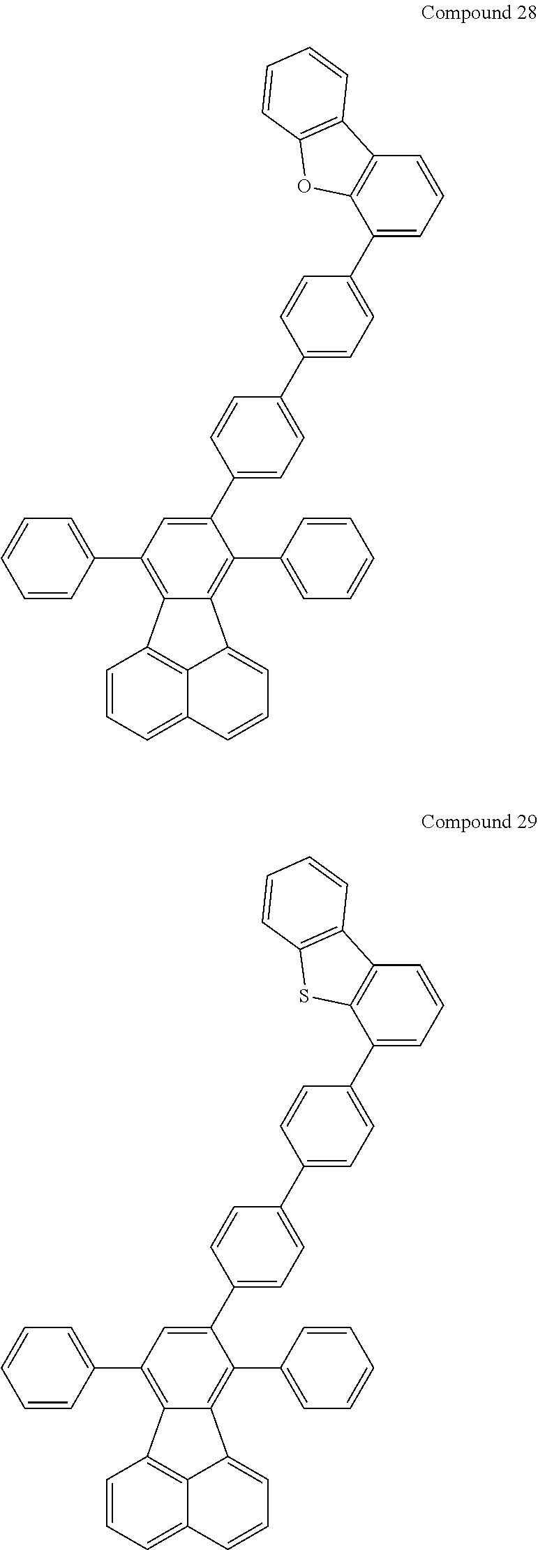


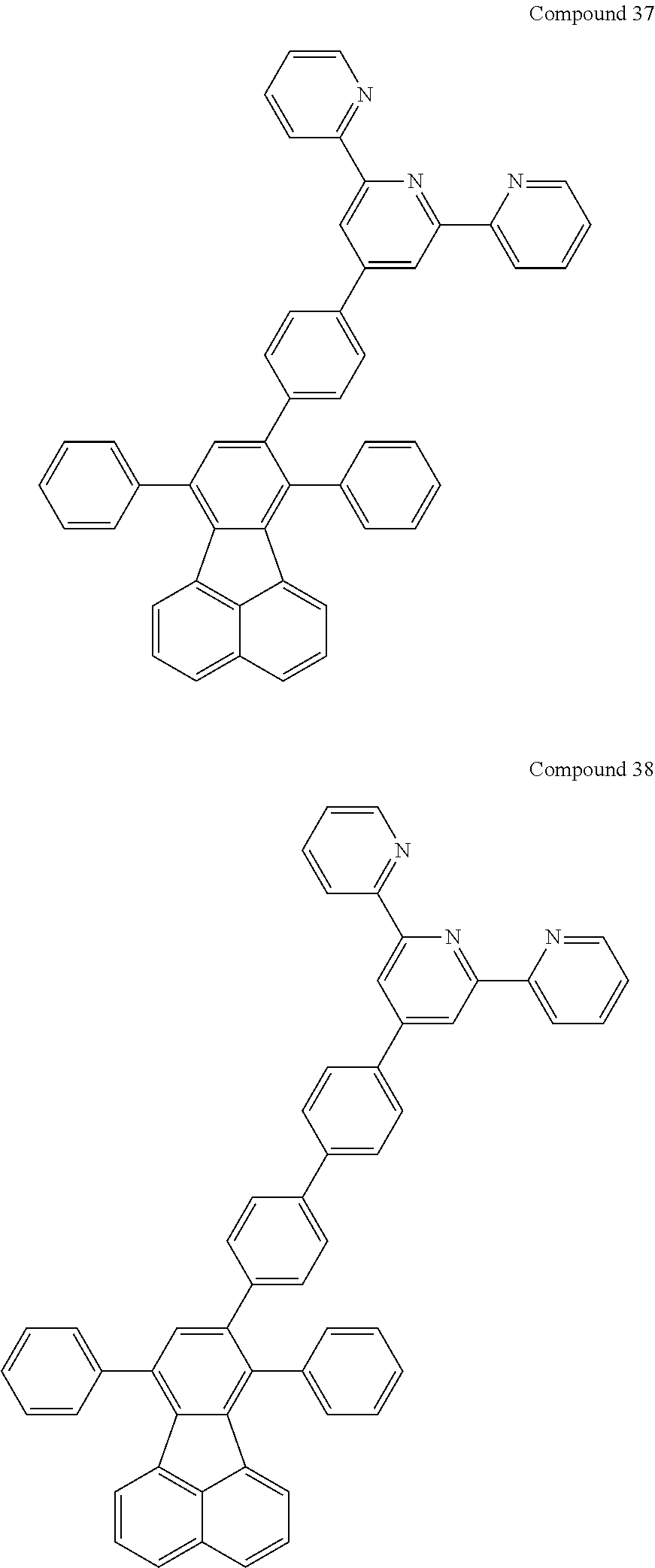


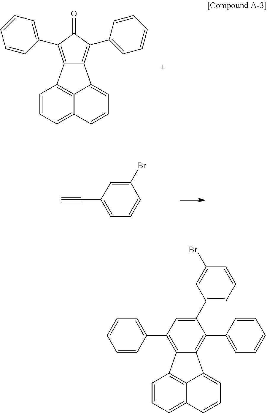

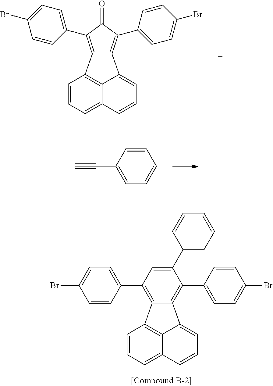


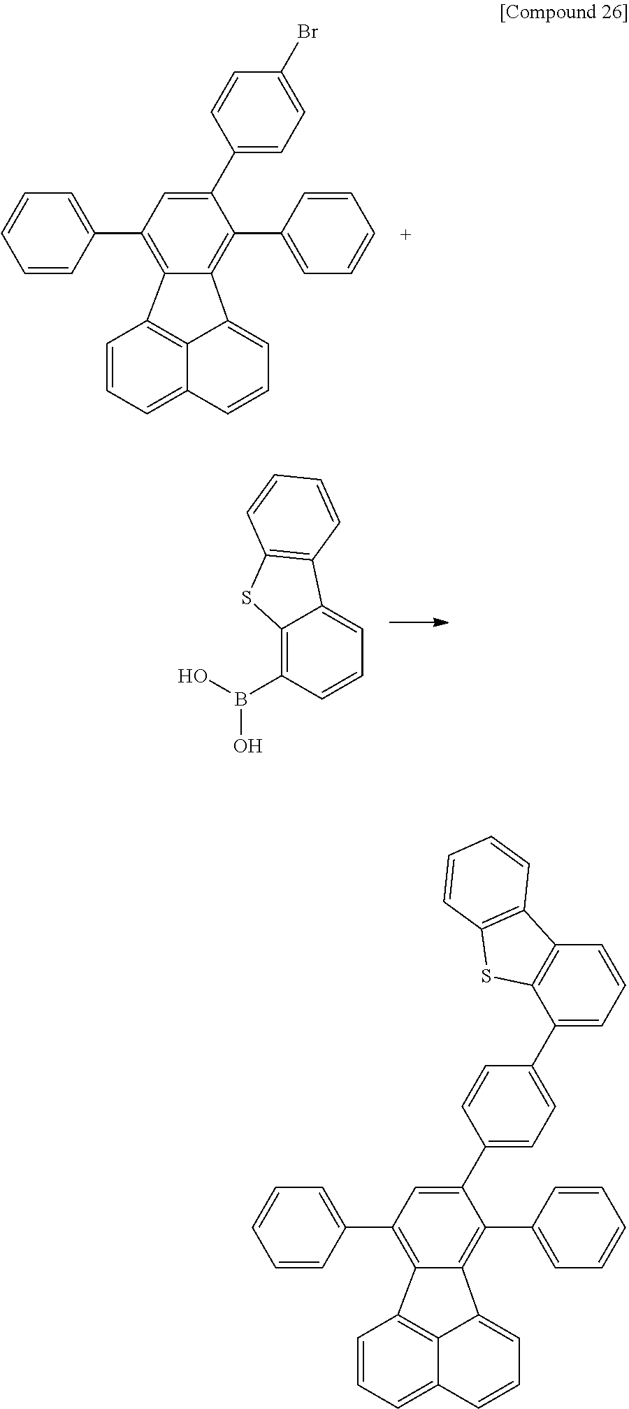


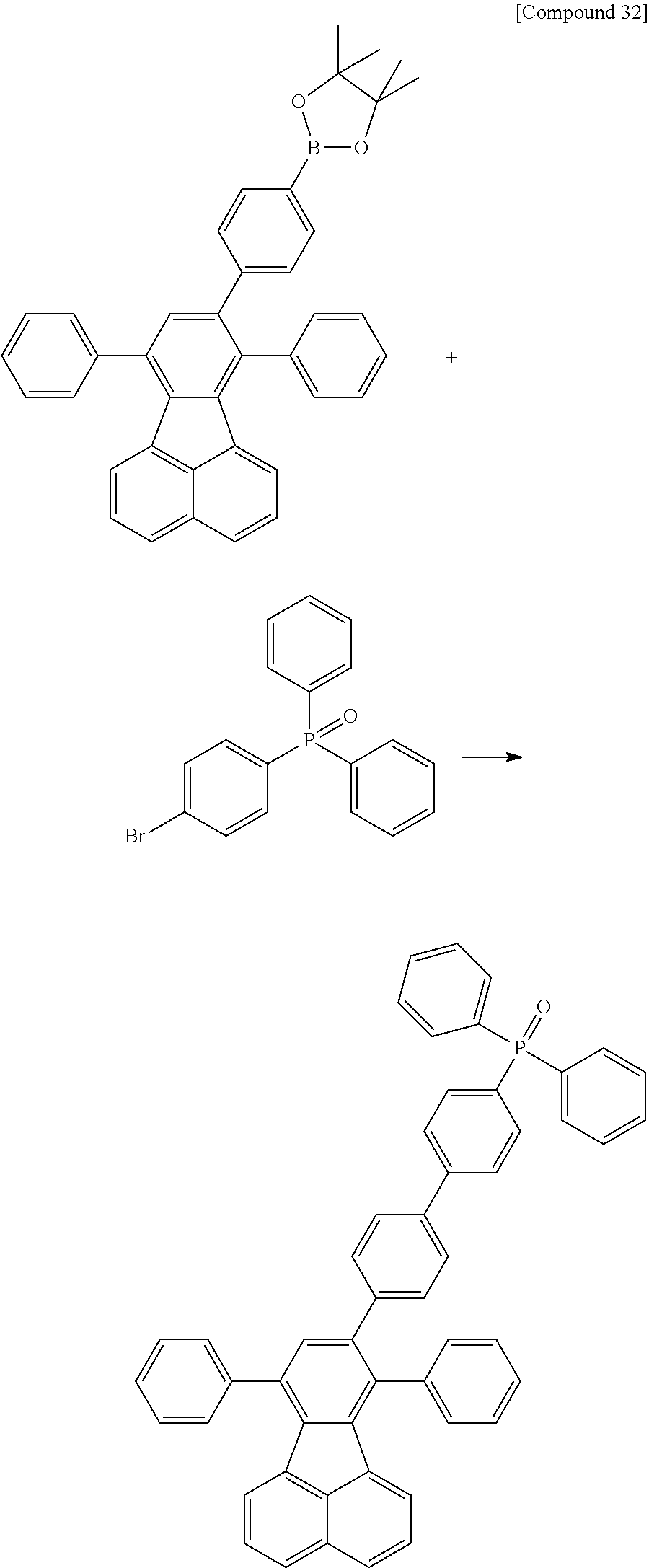


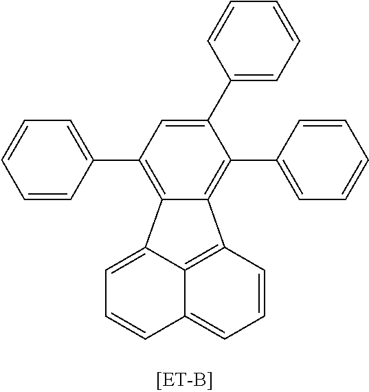
| TABLE 1 | |||||
| Color | |||||
| Voltage | Efficiency | Coordinates | |||
| Compound | (V) | (cd/A) | (x, y) | ||
| |
2 | 3.71 | 41.25 | (0.374, |
| Example 1-1 | 0.621) | |||
| Experimental | 8 | 4.15 | 39.11 | (0.374, |
| Example 1-2 | 0.621) | |||
| Experimental | 11 | 4.10 | 40.20 | (0.374, |
| Example 1-3 | 0.620) | |||
| Experimental | 32 | 4.50 | 37.25 | (0.373, |
| Example 1-4 | 0.618) | |||
| Experimental | 38 | 3.63 | 43.55 | (0.373, |
| Example 1-5 | 0.618) | |||
| Comparative | ET-B | 5.51 | 25.53 | (0.373, |
| Example 1 | 0.617) | |||


| TABLE 2 | |||||
| Color | |||||
| Voltage | Efficiency | Coordinates | |||
| Compound | (V) | (cd/A) | (x, y) | ||
| |
7 | 4.35 | 6.43 | (0.133, |
| Example 2-1 | 0.154) | |||
| |
2 | 4.10 | 6.33 | (0.133, |
| Example 2-2 | 0.153) | |||
| Experimental | 27 | 4.51 | 5.99 | (0.133, |
| Example 2-3 | 0.153) | |||
| Experimental | 38 | 4.22 | 6.25 | (0.134, |
| Example 2-4 | 0.154) | |||
| Comparative | ET-C | 5.21 | 5.51 | (0.134, |
| Example 2 | 0.153) | |||
-
- 1: Substrate
- 2: Anode
- 3: Light Emitting Layer
- 4: Cathode
- 5: Hole Injection Layer
- 6: Hole Transfer Layer
- 7: Electron Transfer Layer
Claims (16)

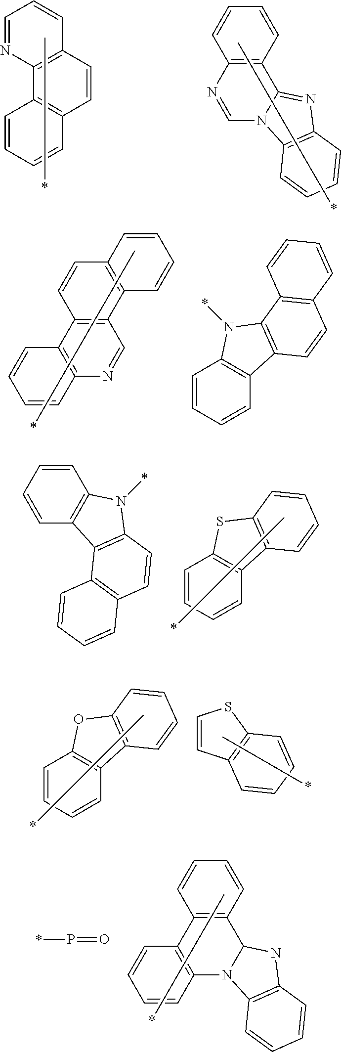


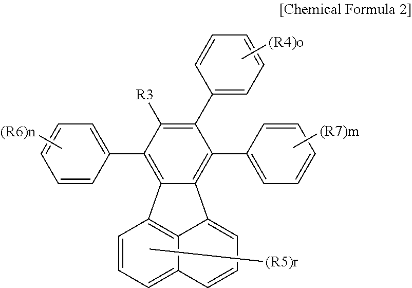

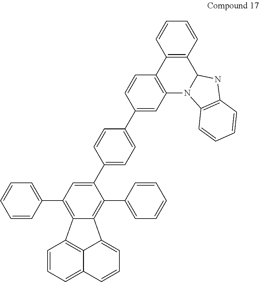


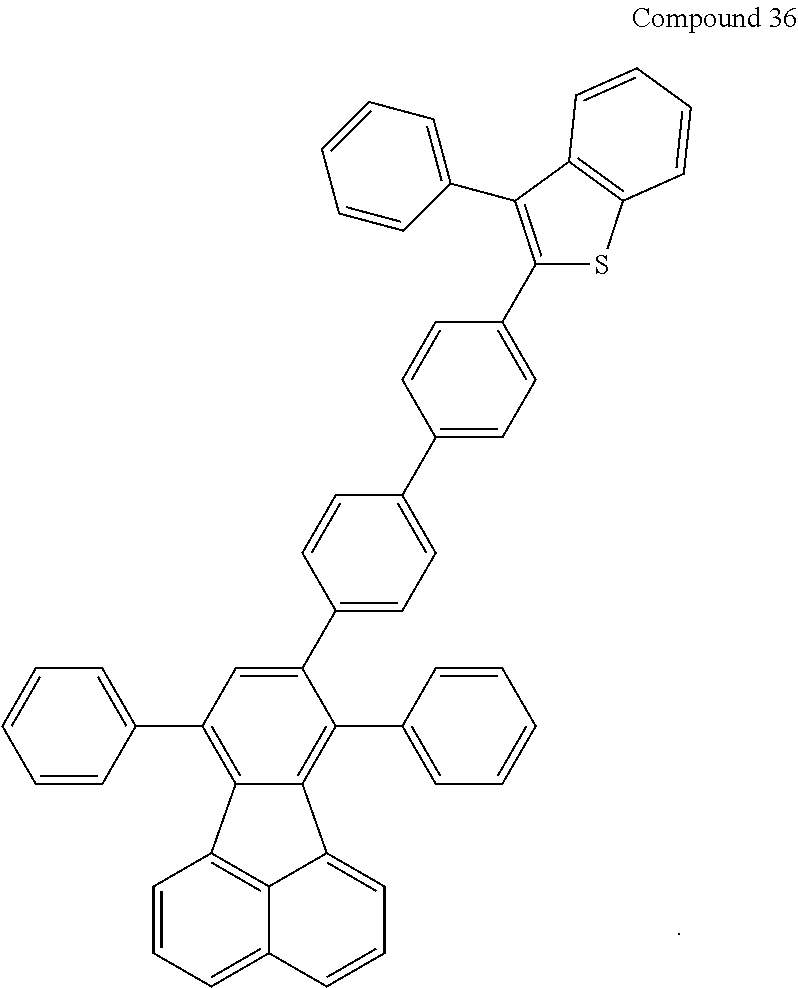


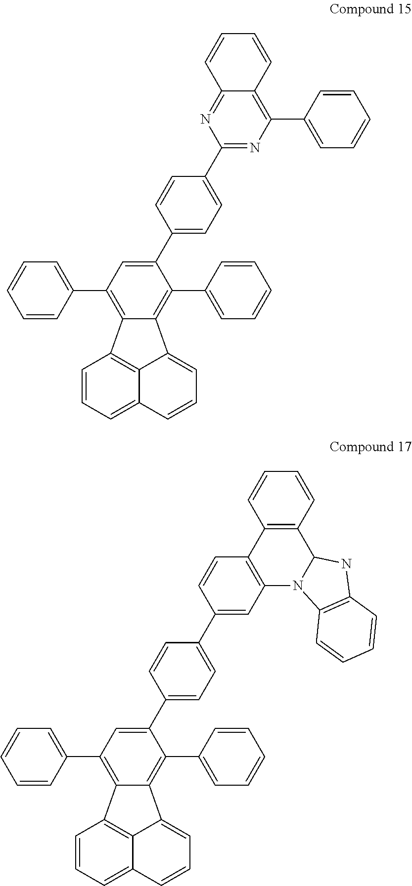

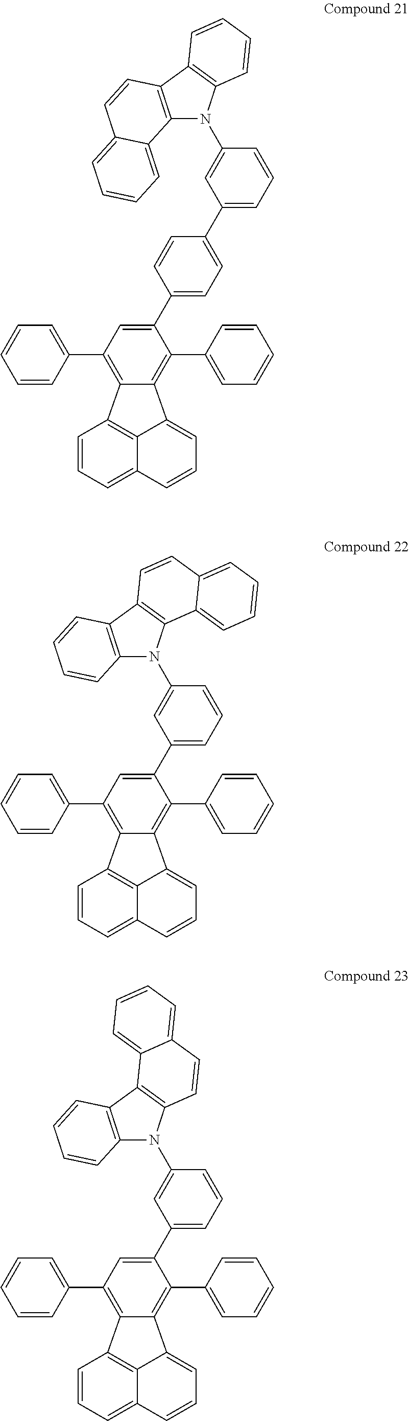


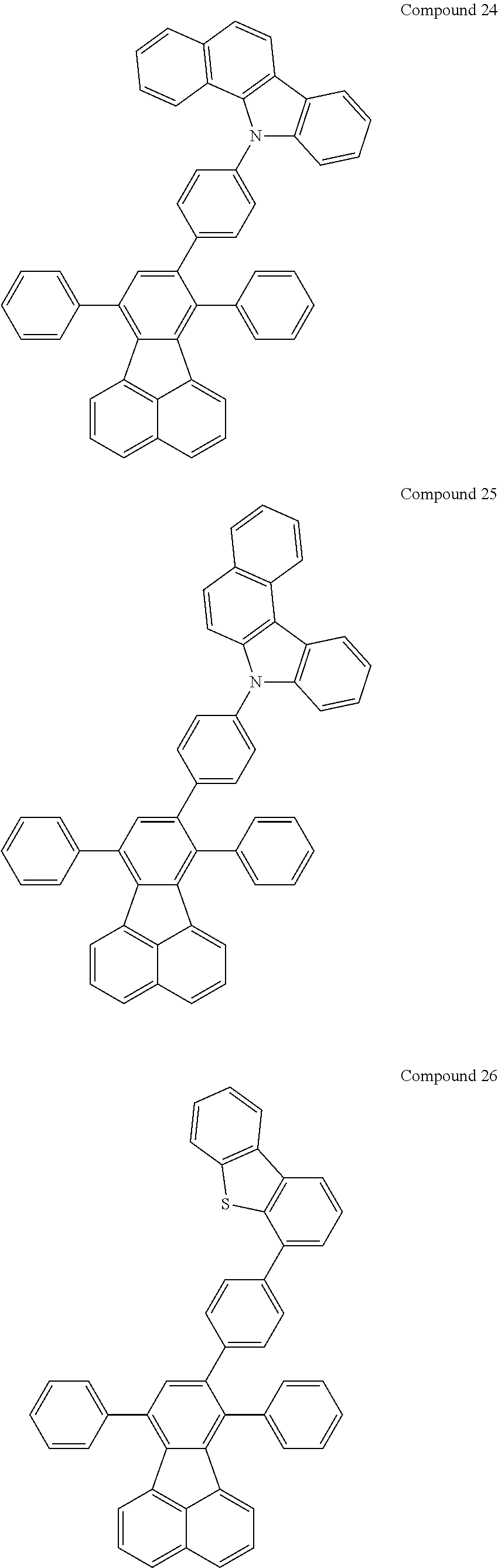


Applications Claiming Priority (3)
| Application Number | Priority Date | Filing Date | Title |
|---|---|---|---|
| KR10-2012-0132190 | 2012-11-21 | ||
| KR20120132190 | 2012-11-21 | ||
| PCT/KR2013/010491 WO2014081168A1 (en) | 2012-11-21 | 2013-11-19 | Fluoranthene compound, and organic electronic device comprising same |
Publications (2)
| Publication Number | Publication Date |
|---|---|
| US20150236273A1 US20150236273A1 (en) | 2015-08-20 |
| US10680182B2 true US10680182B2 (en) | 2020-06-09 |
Family
ID=50776292
Family Applications (1)
| Application Number | Title | Priority Date | Filing Date |
|---|---|---|---|
| US14/429,258 Active 2035-05-14 US10680182B2 (en) | 2012-11-21 | 2013-11-19 | Fluoranthene compound, and organic electronic device comprising same |
Country Status (7)
| Country | Link |
|---|---|
| US (1) | US10680182B2 (en) |
| EP (1) | EP2924020B1 (en) |
| JP (1) | JP6158937B2 (en) |
| KR (2) | KR101775188B1 (en) |
| CN (1) | CN104703969B (en) |
| TW (1) | TWI610920B (en) |
| WO (1) | WO2014081168A1 (en) |
Families Citing this family (35)
| Publication number | Priority date | Publication date | Assignee | Title |
|---|---|---|---|---|
| KR102050484B1 (en) | 2013-03-04 | 2019-12-02 | 삼성디스플레이 주식회사 | Anthracene derivatives and organic light emitting diodes comprising the derivatives |
| KR20160002675A (en) * | 2013-05-02 | 2016-01-08 | 이데미쓰 고산 가부시키가이샤 | Compound, material for organic electroluminescent elements, organic electroluminescent element, and electronic device |
| KR102107106B1 (en) | 2013-05-09 | 2020-05-07 | 삼성디스플레이 주식회사 | Styryl-based compound and organic light emitting diode comprising the same |
| KR102269131B1 (en) | 2013-07-01 | 2021-06-25 | 삼성디스플레이 주식회사 | Compound and organic light emitting device comprising same |
| CN104342126B (en) * | 2013-11-11 | 2017-02-15 | 北京阿格蕾雅科技发展有限公司 | Organic electroluminescent material and organic electroluminescent device |
| US10062850B2 (en) | 2013-12-12 | 2018-08-28 | Samsung Display Co., Ltd. | Amine-based compounds and organic light-emitting devices comprising the same |
| KR101537500B1 (en) | 2014-04-04 | 2015-07-20 | 주식회사 엘지화학 | Organic light emitting diode |
| KR20150115622A (en) * | 2014-04-04 | 2015-10-14 | 주식회사 엘지화학 | Hetero-cyclic compound and organic light emitting device comprising the same |
| KR101542714B1 (en) | 2014-04-04 | 2015-08-12 | 주식회사 엘지화학 | Hetero-cyclic compound and organic light emitting device comprising the same |
| KR20150132795A (en) | 2014-05-16 | 2015-11-26 | 삼성디스플레이 주식회사 | Organic light emitting device |
| EP3150579B1 (en) * | 2014-05-28 | 2021-02-24 | Toray Industries, Inc. | Fluoranthene derivative, electronic device containing same, light-emitting element, and photoelectric conversion element |
| KR102327086B1 (en) * | 2014-06-11 | 2021-11-17 | 삼성디스플레이 주식회사 | Organic light-emitting devices |
| KR101659292B1 (en) | 2014-11-28 | 2016-09-23 | (주)더블유에스 | Phosphoryl substituted Fluoranthene derivatives and organic electroluminescent device including the same |
| KR102611317B1 (en) * | 2014-12-24 | 2023-12-07 | 솔루스첨단소재 주식회사 | Organic compound and organic electro luminescence device comprising the same |
| KR102343145B1 (en) | 2015-01-12 | 2021-12-27 | 삼성디스플레이 주식회사 | Condensed compound and organic light-emitting device comprising the same |
| KR102261644B1 (en) * | 2015-03-11 | 2021-06-08 | 삼성디스플레이 주식회사 | An organic light emitting device |
| KR102364221B1 (en) | 2015-03-23 | 2022-02-18 | 삼성디스플레이 주식회사 | Condensed-cyclic compound and organic light emitting device comprising the same |
| JPWO2016175292A1 (en) * | 2015-04-28 | 2018-02-22 | 出光興産株式会社 | COMPOUND, MATERIAL FOR ORGANIC ELECTROLUMINESCENT ELEMENT, ORGANIC ELECTROLUMINESCENT ELEMENT, AND ELECTRONIC DEVICE |
| US20170229661A1 (en) * | 2015-06-16 | 2017-08-10 | Idemitsu Kosan Co., Ltd. | Compound, material for organic electroluminescence element, organic electroluminescence element, and electronic device |
| KR102458684B1 (en) * | 2015-10-08 | 2022-10-26 | 삼성디스플레이 주식회사 | Organic light emitting device |
| CN106542957B (en) * | 2015-12-09 | 2019-05-14 | 广东阿格蕾雅光电材料有限公司 | Organic Electron Transport Material |
| CN106356452B (en) * | 2015-12-09 | 2018-09-18 | 广东阿格蕾雅光电材料有限公司 | Only electronics organic semiconductor diodes device |
| CN107635966B (en) * | 2015-12-23 | 2021-04-09 | 株式会社Lg化学 | Compounds and organic electronic devices containing the same |
| KR102593530B1 (en) | 2016-01-25 | 2023-10-26 | 삼성디스플레이 주식회사 | An organic light emitting device |
| KR101879846B1 (en) * | 2016-07-29 | 2018-08-17 | 성균관대학교산학협력단 | Organic electroluminescent compounds, producing method of the same and organic electroluminescent device including the same |
| CN107778260A (en) * | 2016-08-24 | 2018-03-09 | 株式会社Lg化学 | Novel organic light-emitting material and organic light-emitting element containing it |
| KR20180022546A (en) * | 2016-08-24 | 2018-03-06 | 주식회사 엘지화학 | Novel organic light emitting material and organic light emitting device comprising the same |
| CN106397291A (en) * | 2016-09-08 | 2017-02-15 | 沈阳化工大学 | Initiator for high-temperature crosslinking and preparation method thereof |
| JP6971561B2 (en) * | 2016-11-11 | 2021-11-24 | キヤノン株式会社 | Photoelectric conversion element, image sensor and image sensor |
| TWI756292B (en) * | 2016-11-14 | 2022-03-01 | 德商麥克專利有限公司 | Compounds having an acceptor group and a donor group |
| CN107833974B (en) * | 2017-07-12 | 2018-11-09 | 北京鼎材科技有限公司 | A kind of novel electroluminescent device |
| CN108047087B (en) * | 2018-01-18 | 2020-06-05 | 河南省科学院化学研究所有限公司 | 3 '- (4-bromonaphthalene-1-yl) [1, 1' -biphenyl ] -4-nitrile and synthesis method thereof |
| KR20210075535A (en) * | 2019-12-13 | 2021-06-23 | 솔루스첨단소재 주식회사 | Organic compound and organic electroluminescent device comprising the same |
| KR102805679B1 (en) * | 2021-06-28 | 2025-05-15 | 엘티소재주식회사 | Heterocyclic compound, and organic light emitting device comprising same |
| WO2024172381A1 (en) * | 2023-02-14 | 2024-08-22 | 주식회사 엘지화학 | Compound and organic light-emitting device comprising same |
Citations (13)
| Publication number | Priority date | Publication date | Assignee | Title |
|---|---|---|---|---|
| JP2003105332A (en) | 2001-09-28 | 2003-04-09 | Canon Inc | Organic light emitting device |
| US20060172147A1 (en) * | 2003-07-11 | 2006-08-03 | Masahide Matsuura | White organic electroluminescence device |
| US20070243411A1 (en) * | 2006-02-28 | 2007-10-18 | Idemitsu Kosan Co., Ltd. | Organic electroluminescence device |
| US20110248257A1 (en) | 2008-12-24 | 2011-10-13 | Nam-Soo Kim | Compound for an organic photoelectric device, organic photoelectric device, and display device including the same |
| KR20110137897A (en) | 2010-06-18 | 2011-12-26 | 주식회사 알파켐 | Fluoranthene derivatives and organic light emitting devices using the same |
| WO2012030145A1 (en) * | 2010-08-31 | 2012-03-08 | Rohm And Haas Electronic Materials Korea Ltd. | Novel compounds for organic electronic material and organic electroluminescent device using the same |
| KR20120029258A (en) | 2010-09-16 | 2012-03-26 | 주식회사 알파켐 | Heteroaromatic cycle compound and organic light emitting diode using the same |
| US20120097924A1 (en) | 2010-10-26 | 2012-04-26 | Samsung Mobile Display Co., Ltd. | Organic light-emitting device |
| JP2012092099A (en) | 2010-10-26 | 2012-05-17 | Samsung Mobile Display Co Ltd | Organic light-emitting element |
| KR20130025087A (en) | 2011-09-01 | 2013-03-11 | 롬엔드하스전자재료코리아유한회사 | Novel organic electroluminescent compounds and organic electroluminescent device using the same |
| CN103319532A (en) | 2012-03-19 | 2013-09-25 | 海洋王照明科技股份有限公司 | Organic semiconductor material, preparation method and electroluminescent device |
| WO2013182046A1 (en) | 2012-06-06 | 2013-12-12 | 广东阿格蕾雅光电材料有限公司 | Organic electronic material and organic electroluminescent device |
| US20140114069A1 (en) * | 2011-03-25 | 2014-04-24 | Ronm and Haas Electronic Materials Korea Ltd. | Novel compounds for organic electronic material and organic electroluminescent device using the same |
Family Cites Families (5)
| Publication number | Priority date | Publication date | Assignee | Title |
|---|---|---|---|---|
| JP4505146B2 (en) | 1999-02-04 | 2010-07-21 | ダウ グローバル テクノロジーズ インコーポレイティド | Fluorene copolymers and devices made therefrom |
| FI121334B (en) | 2004-03-09 | 2010-10-15 | Canatu Oy | Method and apparatus for making carbon nanotubes |
| CN104428916B (en) * | 2012-07-05 | 2016-10-26 | 东丽株式会社 | Light emitting element material and light-emitting component |
| JPWO2014057873A1 (en) * | 2012-10-10 | 2016-09-05 | 東レ株式会社 | Phosphine oxide derivative and light emitting device having the same |
| KR20160002675A (en) * | 2013-05-02 | 2016-01-08 | 이데미쓰 고산 가부시키가이샤 | Compound, material for organic electroluminescent elements, organic electroluminescent element, and electronic device |
-
2013
- 2013-11-19 KR KR1020130140418A patent/KR101775188B1/en active Active
- 2013-11-19 CN CN201380052727.8A patent/CN104703969B/en active Active
- 2013-11-19 EP EP13838080.3A patent/EP2924020B1/en active Active
- 2013-11-19 KR KR1020130140542A patent/KR101739612B1/en active Active
- 2013-11-19 JP JP2015538037A patent/JP6158937B2/en active Active
- 2013-11-19 US US14/429,258 patent/US10680182B2/en active Active
- 2013-11-19 WO PCT/KR2013/010491 patent/WO2014081168A1/en not_active Ceased
- 2013-11-21 TW TW102142400A patent/TWI610920B/en active
Patent Citations (18)
| Publication number | Priority date | Publication date | Assignee | Title |
|---|---|---|---|---|
| JP2003105332A (en) | 2001-09-28 | 2003-04-09 | Canon Inc | Organic light emitting device |
| US20060172147A1 (en) * | 2003-07-11 | 2006-08-03 | Masahide Matsuura | White organic electroluminescence device |
| US20070243411A1 (en) * | 2006-02-28 | 2007-10-18 | Idemitsu Kosan Co., Ltd. | Organic electroluminescence device |
| US20110248257A1 (en) | 2008-12-24 | 2011-10-13 | Nam-Soo Kim | Compound for an organic photoelectric device, organic photoelectric device, and display device including the same |
| JP2012513987A (en) | 2008-12-24 | 2012-06-21 | チェイル インダストリーズ インコーポレイテッド | Novel compound for organic photoelectric device and organic photoelectric device including the same |
| KR20110137897A (en) | 2010-06-18 | 2011-12-26 | 주식회사 알파켐 | Fluoranthene derivatives and organic light emitting devices using the same |
| WO2012030145A1 (en) * | 2010-08-31 | 2012-03-08 | Rohm And Haas Electronic Materials Korea Ltd. | Novel compounds for organic electronic material and organic electroluminescent device using the same |
| KR20120029258A (en) | 2010-09-16 | 2012-03-26 | 주식회사 알파켐 | Heteroaromatic cycle compound and organic light emitting diode using the same |
| JP2012092099A (en) | 2010-10-26 | 2012-05-17 | Samsung Mobile Display Co Ltd | Organic light-emitting element |
| US20120097924A1 (en) | 2010-10-26 | 2012-04-26 | Samsung Mobile Display Co., Ltd. | Organic light-emitting device |
| US20140114069A1 (en) * | 2011-03-25 | 2014-04-24 | Ronm and Haas Electronic Materials Korea Ltd. | Novel compounds for organic electronic material and organic electroluminescent device using the same |
| KR20130025087A (en) | 2011-09-01 | 2013-03-11 | 롬엔드하스전자재료코리아유한회사 | Novel organic electroluminescent compounds and organic electroluminescent device using the same |
| JP2014531419A (en) | 2011-09-01 | 2014-11-27 | ローム・アンド・ハース・エレクトロニック・マテリアルズ・コリア・リミテッド | NOVEL ORGANIC ELECTROLUMINESCENT COMPOUND AND ORGANIC ELECTROLUMINESCENT DEVICE USING THE SAME |
| CN103319532A (en) | 2012-03-19 | 2013-09-25 | 海洋王照明科技股份有限公司 | Organic semiconductor material, preparation method and electroluminescent device |
| WO2013182046A1 (en) | 2012-06-06 | 2013-12-12 | 广东阿格蕾雅光电材料有限公司 | Organic electronic material and organic electroluminescent device |
| CN103468243A (en) | 2012-06-06 | 2013-12-25 | 广东阿格蕾雅光电材料有限公司 | Organic electronic materials and organic electroluminescent device |
| TW201404862A (en) | 2012-06-06 | 2014-02-01 | Guangdong Aglaia Optoectronic Materials Co Ltd | Organic electronic material and organic electroluminescent device |
| US20150108449A1 (en) * | 2012-06-06 | 2015-04-23 | Guangdong Aglaia Optoelectronic Material Co., Ltd | Organic electronic material and organic electroluminescent device |
Non-Patent Citations (4)
| Title |
|---|
| Boonjae Jang, U.S. Appl. No. 14/429,258, filed Mar. 18, 2015, Fluoranthene Compound, and Organic Electronic Device Comprising Same. |
| Chinese Office Action with English translation dated Nov. 18, 2015 in Chinese Patent Application No. 2013800527278 (14 pages). |
| Kim, et al.: "Substituent Effect of Fluoranthene Derivatives in Electroluminescence", Molecular Crystals and Liquid Crystals, Taylor & Francis Group LLC, vol. 498, 2009, pp. 140-150. |
| Tong, Qing-Xiao et al., High-efficiency nondoped green organic light-emitting devices, Chemical Physics Letters, 2008, pp. 79-82, vol. 455. |
Also Published As
| Publication number | Publication date |
|---|---|
| KR20140065342A (en) | 2014-05-29 |
| US20150236273A1 (en) | 2015-08-20 |
| EP2924020A4 (en) | 2016-06-15 |
| JP6158937B2 (en) | 2017-07-05 |
| EP2924020B1 (en) | 2019-01-16 |
| EP2924020A1 (en) | 2015-09-30 |
| TWI610920B (en) | 2018-01-11 |
| KR101739612B1 (en) | 2017-05-24 |
| KR101775188B1 (en) | 2017-09-05 |
| KR20140065345A (en) | 2014-05-29 |
| TW201434818A (en) | 2014-09-16 |
| JP2016505507A (en) | 2016-02-25 |
| WO2014081168A1 (en) | 2014-05-30 |
| CN104703969B (en) | 2017-09-05 |
| CN104703969A (en) | 2015-06-10 |
Similar Documents
| Publication | Publication Date | Title |
|---|---|---|
| US10680182B2 (en) | Fluoranthene compound, and organic electronic device comprising same | |
| US11618754B2 (en) | Nitrogen-containing compound, electronic component and electronic device including same | |
| US12534464B2 (en) | Heterocyclic compound and organic light emitting element comprising same | |
| US9391281B2 (en) | Heterocyclic compound and organic electronic element containing same | |
| US9882145B2 (en) | Hetero ring compound and organic light emitting diode comprising same | |
| US11673875B2 (en) | Organic compound, organic optoelectric diode, and display device | |
| CN103608429B (en) | Compound and organic electronic device using said compound | |
| CN105593336B (en) | Organic light emitting diode | |
| CN105198882B (en) | New compound and organic light-emitting device using the compound | |
| US9203033B2 (en) | Nitrogen-containing heterocyclic compounds and organic electronic device comprising the same | |
| US10995098B2 (en) | Heterocyclic compound and organic light emitting device comprising the same | |
| US10790453B2 (en) | Compounds and organic electronic device using the same | |
| US20230320205A1 (en) | Nitrogen-containing compound, organic electroluminescent device, and electronic apparatus | |
| US20210257552A1 (en) | Organic light-emitting device | |
| US12048240B2 (en) | Organic compound, electronic component and electronic apparatus comprising the same | |
| KR102054397B1 (en) | Hetero-cyclic compound and organic light emitting device comprising the same | |
| US11133477B2 (en) | Heterocyclic compound and organic light emitting element using same | |
| US20210104684A1 (en) | Compound for organic optoelectronic device, organic optoelectronic device and display device | |
| US9960357B2 (en) | Spiro-type compound and organic light emitting element comprising same | |
| CN111212829A (en) | Spiro compound and organic light-emitting device comprising the same | |
| US11678574B2 (en) | Compound and organic light emitting diode comprising same | |
| US11038119B2 (en) | Organic compound, organic optoelectronic device and display apparatus | |
| KR101682766B1 (en) | Amine-based compound and organic light emitting device comprising the same |
Legal Events
| Date | Code | Title | Description |
|---|---|---|---|
| AS | Assignment |
Owner name: LG CHEM, LTD., KOREA, REPUBLIC OF Free format text: ASSIGNMENT OF ASSIGNORS INTEREST;ASSIGNORS:JANG, BOONJAE;LEE, DONG HOON;KIM, KONGKYEOM;AND OTHERS;REEL/FRAME:035223/0650 Effective date: 20150212 |
|
| AS | Assignment |
Owner name: LG CHEM, LTD., KOREA, REPUBLIC OF Free format text: CORRECTIVE ASSIGNMENT TO CORRECT TO ADD LAST ASSIGNORS NAME PREVIOUSLY RECORDED AT REEL: 035223 FRAME: 0650. ASSIGNOR(S) HEREBY CONFIRMS THE ASSIGNMENT;ASSIGNORS:JANG, BOONJAE;LEE, DONG HOON;KIM, KONGKYEOM;AND OTHERS;REEL/FRAME:035549/0570 Effective date: 20150212 |
|
| STPP | Information on status: patent application and granting procedure in general |
Free format text: DOCKETED NEW CASE - READY FOR EXAMINATION |
|
| STPP | Information on status: patent application and granting procedure in general |
Free format text: NON FINAL ACTION MAILED |
|
| STPP | Information on status: patent application and granting procedure in general |
Free format text: RESPONSE TO NON-FINAL OFFICE ACTION ENTERED AND FORWARDED TO EXAMINER |
|
| STPP | Information on status: patent application and granting procedure in general |
Free format text: FINAL REJECTION MAILED |
|
| STPP | Information on status: patent application and granting procedure in general |
Free format text: RESPONSE AFTER FINAL ACTION FORWARDED TO EXAMINER |
|
| STPP | Information on status: patent application and granting procedure in general |
Free format text: DOCKETED NEW CASE - READY FOR EXAMINATION |
|
| STPP | Information on status: patent application and granting procedure in general |
Free format text: NOTICE OF ALLOWANCE MAILED -- APPLICATION RECEIVED IN OFFICE OF PUBLICATIONS |
|
| STCF | Information on status: patent grant |
Free format text: PATENTED CASE |
|
| CC | Certificate of correction | ||
| MAFP | Maintenance fee payment |
Free format text: PAYMENT OF MAINTENANCE FEE, 4TH YEAR, LARGE ENTITY (ORIGINAL EVENT CODE: M1551); ENTITY STATUS OF PATENT OWNER: LARGE ENTITY Year of fee payment: 4 |