US10627266B2 - Flowmeter with discontinuous helicoid turbine - Google Patents
Flowmeter with discontinuous helicoid turbine Download PDFInfo
- Publication number
- US10627266B2 US10627266B2 US15/717,632 US201715717632A US10627266B2 US 10627266 B2 US10627266 B2 US 10627266B2 US 201715717632 A US201715717632 A US 201715717632A US 10627266 B2 US10627266 B2 US 10627266B2
- Authority
- US
- United States
- Prior art keywords
- segments
- spinner member
- downhole device
- spinner
- fluid
- Prior art date
- Legal status (The legal status is an assumption and is not a legal conclusion. Google has not performed a legal analysis and makes no representation as to the accuracy of the status listed.)
- Expired - Fee Related, expires
Links
Images


Classifications
-
- G—PHYSICS
- G01—MEASURING; TESTING
- G01F—MEASURING VOLUME, VOLUME FLOW, MASS FLOW OR LIQUID LEVEL; METERING BY VOLUME
- G01F1/00—Measuring the volume flow or mass flow of fluid or fluent solid material wherein the fluid passes through a meter in a continuous flow
- G01F1/05—Measuring the volume flow or mass flow of fluid or fluent solid material wherein the fluid passes through a meter in a continuous flow by using mechanical effects
- G01F1/10—Measuring the volume flow or mass flow of fluid or fluent solid material wherein the fluid passes through a meter in a continuous flow by using mechanical effects using rotating vanes with axial admission
-
- E—FIXED CONSTRUCTIONS
- E21—EARTH OR ROCK DRILLING; MINING
- E21B—EARTH OR ROCK DRILLING; OBTAINING OIL, GAS, WATER, SOLUBLE OR MELTABLE MATERIALS OR A SLURRY OF MINERALS FROM WELLS
- E21B47/00—Survey of boreholes or wells
- E21B47/10—Locating fluid leaks, intrusions or movements
-
- F—MECHANICAL ENGINEERING; LIGHTING; HEATING; WEAPONS; BLASTING
- F01—MACHINES OR ENGINES IN GENERAL; ENGINE PLANTS IN GENERAL; STEAM ENGINES
- F01D—NON-POSITIVE DISPLACEMENT MACHINES OR ENGINES, e.g. STEAM TURBINES
- F01D5/00—Blades; Blade-carrying members; Heating, heat-insulating, cooling or antivibration means on the blades or the members
- F01D5/12—Blades
- F01D5/14—Form or construction
- F01D5/141—Shape, i.e. outer, aerodynamic form
- F01D5/146—Shape, i.e. outer, aerodynamic form of blades with tandem configuration, split blades or slotted blades
-
- F—MECHANICAL ENGINEERING; LIGHTING; HEATING; WEAPONS; BLASTING
- F05—INDEXING SCHEMES RELATING TO ENGINES OR PUMPS IN VARIOUS SUBCLASSES OF CLASSES F01-F04
- F05D—INDEXING SCHEME FOR ASPECTS RELATING TO NON-POSITIVE-DISPLACEMENT MACHINES OR ENGINES, GAS-TURBINES OR JET-PROPULSION PLANTS
- F05D2240/00—Components
- F05D2240/20—Rotors
- F05D2240/30—Characteristics of rotor blades, i.e. of any element transforming dynamic fluid energy to or from rotational energy and being attached to a rotor
-
- F—MECHANICAL ENGINEERING; LIGHTING; HEATING; WEAPONS; BLASTING
- F05—INDEXING SCHEMES RELATING TO ENGINES OR PUMPS IN VARIOUS SUBCLASSES OF CLASSES F01-F04
- F05D—INDEXING SCHEME FOR ASPECTS RELATING TO NON-POSITIVE-DISPLACEMENT MACHINES OR ENGINES, GAS-TURBINES OR JET-PROPULSION PLANTS
- F05D2250/00—Geometry
- F05D2250/20—Three-dimensional
- F05D2250/25—Three-dimensional helical
Definitions
- the present disclosure relates in general to a system for use in monitoring flow in a wellbore. More specifically, the present disclosure relates to a flow meter that employs a helicoid shaped turbine that is discontinuous along its length.
- Flowmeters are typically included with fluid flow lines, where there is a desire or a need to have an estimate of the fluid flow rate in the flow line. Such a need or desire often occurs in facilities such as refineries, chemical processing plants, terminals for loading and offloading fluids, transmission pipelines, and the like.
- Some flowmeters are disposed external to a flow line, but most flowmeters have components within the flow line that interact with the fluid to obtain a measure of the flowrate.
- Some flowmeters include rotating elements, such as spinners, that rotate in response to the fluid flowing past the flow meter. These flow meters monitor the rotational velocity of the rotating element and correlate it to the fluid velocity.
- Other types of flow meters introduce a temporary restriction in the cross sectional area of the fluid stream and monitor a pressure differential created by flowing the fluid across the restriction.
- Spinner type flowmeters generally include a propeller like member having blades that are oriented transverse to a direction of the flow.
- the propeller like member is usually mounted on a rotatable shaft, so that when the flowing fluid causes the propeller to rotate, monitoring shaft rotation yields an indication of fluid flow rate.
- Another type of spinner is formed by twisting a planar element into a helicoid, which also rotates when disposed in a flow of fluid.
- the helicoid is typically oriented in the flow stream so that an axis of the helicoid is parallel with a direction of the fluid flow.
- Helicoids which are often referred to as helical spinners, are usually equipped with magnets along their lateral edges.
- Helical spinner rotational rate is estimated by using sensors that are spaced lateral to the helical spinners, and that sense the location and speed of the magnets.
- sensor location in the flowmeters is often dictated by sensor design or space limitations in the flowmeters. Meeting the constraints introduced by sensor location or spacing affects the helicoid profile, which can result in less than optimal helical spinner designs.
- a downhole device for use in a wellbore, and which includes a housing, a connector on the housing that selectively connects to a conveyance member, and a flowmeter coupled with the housing.
- the flowmeter is equipped with a helicoid shaped spinner member that selectively rotates in response to being disposed in a flow of fluid, the spinner member having a discontinuous surface that defines segments with opposing axial ends that are angularly offset from one another.
- the flowmeter further has features on the spinner member that orbit along a circular path with rotation of the spinner member, and sensors that selectively sense a position of the features.
- adjacent segments are joined to one another by a coupling, and wherein the adjacent segments are spaced axially apart from one another.
- the coupling is optionally a planar member or a helicoid shaped member.
- adjacent segments have different values of pitch.
- adjacent segments have different lengths.
- the features optionally are made of magnets.
- the segments have a forward segment, and wherein a leading edge of the forward segment extends along a path that is generally oblique with an axis of the spinner member.
- a downhole device for use in a wellbore, and which includes a flowmeter with helicoid shaped segments that are coupled together end to end to define a spinner member that is selectively disposed in a flow of fluid, and discontinuities on an outer surface of the spinner member that are formed by separations between the segments.
- a sensor is included with the flowmeter that selectively senses a rotational rate of the spinner member.
- the segments are angularly offset.
- the segments alternatively have different value of pitch, and can have different lengths.
- Connectors are optionally provided between adjacent segments that couple the segments together.
- Also disclosed herein is an example of a method of operating a downhole device in a wellbore, the steps being sensing a rotational rate of a spinner member disposed in the downhole device, and which includes segments coupled end to end and discontinuities along interfaces where the segments are coupled to one another, and estimating a rate of a flow of fluid in the wellbore based on the sensed rotational rate.
- the discontinuity is an angular offset between a trailing edge of a segment and a leading edge of an adjacent segment.
- a magnet is optionally disposed on a lateral edge of the spinner member, and wherein sensing a rotational rate of the spinner member involves sensing the presence of the magnet at a location in a point in time.
- the shapes of the segments are configured to maximize a sensitivity of the spinner member in response to the flow of fluid.
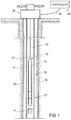
- FIG. 1 is a side partial sectional view of an example of a downhole device disposed in a wellbore and which has a flowmeter for measuring a flow of fluid in the wellbore.
- FIG. 2 is a schematic example of a spinner assembly for use with the flowmeter of FIG. 1 .
- FIG. 3 is a perspective view of an example embodiment of a spinner member for use with the spinner assembly of FIG. 2 .
- FIG. 3A is a schematic of a helicoid with an example of a spinner member superimposed thereon.
- FIG. 4 is a perspective view of an example of a spinner assembly having the spinner member of FIG. 3 .
- FIG. 5 is an axial view of an example of the spinner member of FIG. 3 and taken along lines 5 - 5 .
- FIG. 1 Shown in a partial side sectional view in FIG. 1 is one example of a downhole device 10 which has an elongate housing 12 and is disposed in a length of production tubing 14 .
- Tubing 14 is installed in a wellbore 16 that is shown intersecting a formation 18 .
- Casing 20 lines the wellbore 16 and provides selective isolation of wellbore 16 from formation 18 .
- Perforations may be selectively formed through the casing 20 to allow fluid within formation 18 to make its way into wellbore 16 and into production tubing 14 .
- a flow of fluid F produced from within formation 18 is shown within tubing 14 and making its way towards housing 12 . Examples exist wherein the flow of fluid F includes liquid, gas, vapor, condensate, and combinations thereof.
- An example of a flow meter 22 is included with housing 12 and which is equipped for monitoring flowrate information about the flow of fluid F.
- Downhole device 10 is shown deployed within wellbore 16 on a conveyance means 24 , that can be a wireline, coiled tubing or slick line.
- Conveyance means 24 depends into the wellbore 16 from a wellhead assembly 26 shown on surface and mounted at an opening of the wellbore 16 .
- conveyance means 24 connects to a surface truck (not shown) on the surface and disposed outside of wellbore 16 .
- conveyance means 24 mounts to a spool mounted on an operations or drilling rig, such as when wellbore 16 is subsea.
- a controller 28 which in an example is included within surface truck, is shown coupled to a communication means 30 , so that controller 28 is in selective communication with downhole device 10 via conveyance means 30 .
- Examples of controller 28 are any type of information handling unit, including a processor for processing data received from downhole device 10 , transmitting instructions from controller 28 to downhole device 10 , and which includes hardware for storing electronic information.
- spinner assembly 32 which is included with flow meter 22 .
- spinner assembly 32 includes one embodiment of a spinner member 34 illustrated rotatably coupled to a pair of elongated shafts 36 , 38 , that mount respectively onto supports 40 , 42 .
- Spinner member 34 and shafts 36 , 38 as shown are generally coaxial with one another, and substantially transverse to supports 40 , 42 .
- Supports 40 , 42 project radially outward from housing 12 and in the portion of tool 10 having flow meter 22 .
- Spinner member 34 of FIG. 2 includes a number of segments 44 1-n that are axially oriented to make up the length of the spinner member 34 .
- Magnets 46 1-n , 48 1-n are shown mounted on opposing lateral edges of each segment 44 1-n , and which can be made of permanent magnets that continuously generate a magnetic field, or electro-magnets that selectively generate a detectable magnetic field.
- Spinner member 34 rotates, as illustrated in the example of arrow A R , in response to the flow of fluid F.
- Shafts 36 , 38 are optionally rotated with, or with respect to, spinner member 34 .
- a series of sensors 50 1-n are shown coupled onto housing 12 and which are generally axially located to correspond to magnets 46 1-n , 48 1-n .
- the rotational rate of spinner member 34 can be estimated based on a time stamp of the action of sensing a particular one of the magnets 46 1-n , 48 1-n .
- the direction of rotation of spinner member 34 can be determined by analysis of data signals collected by sensors 50 1-n .
- Leading edges 52 1-n are shown defined on an axial edge of each of the segments 44 1-n that is proximate the origin of the flow of fluid F.
- following edges 54 1-n are defined along an axial ledge of each segment 44 1-n and distal from the direction of the flow of fluid F; and thus on an opposite axial edge of each segment 44 1-n .
- embodiments exist wherein the direction of the flow of fluid F is reversed so that the fluid would reach the following edges 54 1-n before reaching the corresponding leading edges 52 1-n .
- gaps or spaces are provided between the following edges 54 1-n and each adjacent leading edge 52 1-n .
- FIG. 2 is in schematic form where the segments 44 1-n are each represented as planar members and generally coplanar with the other segments 44 1-n .
- alternate examples exist where the segments 44 1-n are shaped so that the adjacent leading and following edges 52 1-n , 54 1-n are not axially aligned or parallel, but angularly offset from one another about axis A X .
- the angular offsets of the individual segments 44 1-n provides for a spinner member 34 that is more sensitive to a wide range of flows; and yet provides for the placement of magnets 46 1-n , 48 1-n on the lateral sides 56 1-n , 58 1-n of the segments 44 1-n so they are axially aligned with the sensors 50 1-n provided on tool 10 .
- each of segments 44 A 1 - 44 A 3 are generally planar members and shaped into a helicoid configuration and about an axis A X .
- a recess 60 A is shown formed on an axial terminal end of segment 44 A 1 and configured so that shaft 36 A (shown in dashed outline) can be received within recess 60 A.
- a corresponding recess 62 A is formed on an axial terminal edge of segment 44 A 3 and on a side of the spinner member 34 A opposite from recess 60 A.
- shaft 38 A mounts into segment 44 A 3 via recess 62 A.
- Receptacles 64 A, 66 A respectively in the segments 44 A 1 , 44 A 3 receive the ends of shafts 36 A, 38 A therein.
- the outer surfaces of segments 44 A 1 , 44 A 3 project radially outward to accommodate the presence of receptacles 64 A, 66 A.
- Pockets 68 A 1-3 are shown formed along lateral edges 56 A 1-3 and provide a place for magnets (not shown) to be inserted therein.
- pockets 70 A 1-3 are formed on lateral edges 58 A 1-3 and for receiving magnets (not shown) therein.
- a generally planar web 72 A is shown with one axial end coupled with following edge 54 A 1 of segment 44 A 1 , and an opposing axial end coupled with leading edge 52 A 2 of segment 44 A 2 , thereby coupling segments 44 A 1 , 44 A 2 to one another.
- a polar coordinate system is illustrated having axes X, Y, Z and radius r. Angles theta ⁇ , phi ⁇ , and gamma ⁇ represent angular offsets between radius r and axes Z, Y, and X respectively. In this example, axis Z is substantially aligned with axis A X .
- segments 44 A 2 and 44 A 3 are coupled to one another by a generally helicoid shaped connector 74 A, with opposing axial ends that connect to edges 54 A 2 , 52 A 3 .
- a generally helicoid shaped connector 74 A to affix adjacent segments 44 A 1-3 introduces a design flexibility so that as depicted adjacent leading and following edges 52 A 1-3 , 54 A 1-3 of the segments 44 A 1-3 are not parallel but angularly offset from one another, such as by angle phi ⁇ .
- angular offsets above axis Z or axis AX, and that are represented by angle phi ⁇ are optionally referred to as azimuthal offsets or azimuthal differences.
- Angularly offsetting leading and following edges 52 A 1-3 , 54 A 1-3 positions the lateral edges 56 A 1-3 , 58 A 1-3 of the segments 44 A 1-3 so that they extend along paths that each resemble a discontinuous helix.
- the lateral edges 56 A 1-3 , 58 A 1-3 of the illustrated embodiment do not extend along smooth helical paths that are continuously generally oblique with axis A X , but instead have portions extending along paths that are angled to be more parallel to axis A X .
- the transverse portions are proximate interfaces between adjacent leading and following edges 52 A 1-3 , 54 A 1-3 .
- the transverse portions so that the angles of the paths with respect to the axis A X are abruptly changed over a relatively short distance.
- FIG. 3A Shown in a side perspective view in FIG. 3A is an example of a helicoid member 75 B with lateral edges that extend along paths that approximate continuous helixes.
- superimposed onto the helicoid member 75 B is spinner member 34 B whose segments 44 B 1-3 have adjacent leading and following edges 52 B 1-3 , 54 B 1-3 that are axially and angularly offset from one another about axis A X .
- the comparative illustration provided in FIG. 3A provides an example of how the lateral edges 56 B 1-3 , 58 B 1-3 of helicoid member spinner member 34 B define discontinuous helixes, and which are different from that of the lateral edges of a helicoid.
- path P 1 as shown runs substantially parallel with a lateral edge of helicoid member 75 B, and while an angular orientation of path P 1 changes with respect to different axial locations along helicoid member 75 B, an angle between path P 1 and axis A X is substantially the same along the length of helicoid member 75 B.
- line L 1 which extends from a radial end of trailing edge 54 B 1 to the closest radial end of leading edge 54 B 2 , is oriented along a path that is more parallel to axis A X than path P 1 .
- segment 44 B 2 is oriented so that leading edge 52 B 2 is offset from trailing edge 54 B 1 in a clockwise direction (when viewed axially from segment 44 B 1 ).
- segment 44 B 2 is oriented so that leading edge 52 B 2 is offset from trailing edge in a counterclockwise direction, so that L 1 would be oriented more transverse to axis A X than path P 1 .
- line L 2 is shown which extends from a radial end of trailing edge 54 B 2 to the closest radial end of leading edge 54 B 3 , is also oriented along a path that is more parallel to axis A X than path P 1 .
- An advantage of the segments 44 A 1-3 that are angularly offset from one another is that the pockets 68 A 1-3 , 70 A 1-3 can be set at axial locations along spinner member 34 A and to accommodate design or manufacturing constraints of associated sensors (not shown). Moreover, the shape and contour of spinner member 34 A is formed to have maximum sensitivity to the flow of fluid F ( FIG. 2 ) so that rotational rates of the spinner member 34 A can provide precise and meaningful results that represent a flow rate of the flow of fluid running adjacent tool 10 .
- FIG. 4 shows in a side perspective view an example of the flow meter 12 A of tool 10 A and illustrates spinner member 34 A mounted on shafts 36 A, 38 A.
- the supports 40 A, 42 A each have a cylindrical portion 76 A, 78 A with an opening that receives ends of shafts 36 A, 38 A that is distal from spinner member 32 A.
- Ports 40 A, 42 A further include brackets 80 A, 82 A which extend from a surface of the cylindrical portions 76 A, 78 A and engage housing 12 A of tool 10 A.
- Brackets 80 A, 82 A are generally elongate members that have a rectangular cross-section along a line perpendicular to axis A X , and which increases in size with distance away from the cylindrical portions 76 A, 78 A. Further illustrated in the example of FIG. 4 are magnets 48 A 1-3 disposed in pockets 70 A 1-3 , where the pockets 70 A 1-3 are disposed on lateral edges of the spinner member 34 A.
- FIG. 5 shows in an axial end view one example of spinner member 34 A of FIG. 3 and taken along lines 5 - 5 .
- an angular offset is illustrated between following edge 54 A 1 and leading edge 52 A 2 , and which is represented by angle phi ⁇ 1 .
- an angularoffset between following edge 54 A 2 and leading edge 52 A 3 is shown, and which is represented by angle phi ⁇ 2 . Further shown in FIG.
- the segments 44 A 1-3 cover substantially 360° around the axis A X , thereby maximizing the surface area in contact with fluid hitting spinner member 34 A and thus maximizing sensitivity and preciseness of readings for data recorded with the flow meter 22 ( FIG. 1 ).
Landscapes
- Engineering & Computer Science (AREA)
- Physics & Mathematics (AREA)
- Fluid Mechanics (AREA)
- Geology (AREA)
- Life Sciences & Earth Sciences (AREA)
- Mining & Mineral Resources (AREA)
- Geophysics (AREA)
- Environmental & Geological Engineering (AREA)
- General Life Sciences & Earth Sciences (AREA)
- Geochemistry & Mineralogy (AREA)
- Mechanical Engineering (AREA)
- General Engineering & Computer Science (AREA)
- General Physics & Mathematics (AREA)
- Measuring Volume Flow (AREA)
Abstract
Description
Claims (16)
Priority Applications (2)
| Application Number | Priority Date | Filing Date | Title |
|---|---|---|---|
| US15/717,632 US10627266B2 (en) | 2017-09-27 | 2017-09-27 | Flowmeter with discontinuous helicoid turbine |
| PCT/US2018/050947 WO2019067228A1 (en) | 2017-09-27 | 2018-09-13 | Flowmeter with discontinuous helicoid turbine |
Applications Claiming Priority (1)
| Application Number | Priority Date | Filing Date | Title |
|---|---|---|---|
| US15/717,632 US10627266B2 (en) | 2017-09-27 | 2017-09-27 | Flowmeter with discontinuous helicoid turbine |
Publications (2)
| Publication Number | Publication Date |
|---|---|
| US20190094052A1 US20190094052A1 (en) | 2019-03-28 |
| US10627266B2 true US10627266B2 (en) | 2020-04-21 |
Family
ID=65808692
Family Applications (1)
| Application Number | Title | Priority Date | Filing Date |
|---|---|---|---|
| US15/717,632 Expired - Fee Related US10627266B2 (en) | 2017-09-27 | 2017-09-27 | Flowmeter with discontinuous helicoid turbine |
Country Status (2)
| Country | Link |
|---|---|
| US (1) | US10627266B2 (en) |
| WO (1) | WO2019067228A1 (en) |
Families Citing this family (1)
| Publication number | Priority date | Publication date | Assignee | Title |
|---|---|---|---|---|
| FR3082224B1 (en) * | 2018-06-07 | 2020-05-22 | Openfield | MINI-TURBINE FLOWMETER AND DOWNHOLE TOOL COMPRISING A MINI-TURBINE FLOWMETER ARRAY FOR OPERATING IN A HYDROCARBON WELL. |
Citations (42)
| Publication number | Priority date | Publication date | Assignee | Title |
|---|---|---|---|---|
| US1893233A (en) * | 1931-02-16 | 1933-01-03 | Nathaniel D Hull | Liquid flow indicator |
| US2552651A (en) * | 1947-09-10 | 1951-05-15 | John F Skold | Fan wheel with arcuate blade forming strips |
| US2741916A (en) | 1953-04-06 | 1956-04-17 | Phillips Petroleum Co | Flowmeter |
| US3036460A (en) * | 1959-04-10 | 1962-05-29 | Jersey Prod Res Co | Fluid meter |
| US3145566A (en) | 1958-04-01 | 1964-08-25 | Rockwell Mfg Co | Meter for measuring the rate of flow by weight of a fluid |
| US3244002A (en) * | 1963-05-10 | 1966-04-05 | North American Aviation Inc | Segmented ball valve and flowmeter |
| US3427879A (en) | 1965-06-25 | 1969-02-18 | Gilbert C Davis | Flow meter |
| US3504990A (en) * | 1967-05-09 | 1970-04-07 | David B Sugden | Undulating flow promoting rotor and assemblies embodying same |
| US3512904A (en) * | 1968-05-24 | 1970-05-19 | Clifford H Allen | Progressing cavity helical pump |
| US3604265A (en) * | 1969-03-19 | 1971-09-14 | Neptune Meter Co | Fluid-driven mass flowmeter |
| US3863806A (en) * | 1973-10-09 | 1975-02-04 | Jr Ross Eugene Risser | Turbine meter |
| US4178127A (en) | 1975-08-27 | 1979-12-11 | Zahorecz Zoltan P | Variable pitch impeller |
| EP0031629A1 (en) | 1979-12-21 | 1981-07-08 | Nevamo Inc. | Flow rate meter |
| US4345480A (en) | 1978-02-21 | 1982-08-24 | Basham Edward R | Rotary flow meter |
| US4482305A (en) | 1977-12-28 | 1984-11-13 | Orszagos Koolaj Es Gazipari Troszt | Axial flow apparatus with rotating helical chamber and spindle members |
| US4500259A (en) * | 1981-08-18 | 1985-02-19 | Schumacher Berthold W | Fluid flow energy converter |
| US4718824A (en) * | 1983-09-12 | 1988-01-12 | Institut Francais Du Petrole | Usable device, in particular for the pumping of an extremely viscous fluid and/or containing a sizeable proportion of gas, particularly for petrol production |
| US4852401A (en) | 1988-06-20 | 1989-08-01 | Halliburton Logging Services Inc. | Well fluid flow velocity measuring apparatus including a spinner cartridge assembly |
| US5433118A (en) * | 1993-12-10 | 1995-07-18 | Contadores De Agua De Zaragoza | Magnetic turbine rotor for low flow fluid meter |
| US5439359A (en) * | 1991-10-23 | 1995-08-08 | Leroy; Andre | Rotary positive displacement machine with helicoid surfaces of particular shapes |
| US5890875A (en) * | 1997-01-27 | 1999-04-06 | Silvano; David | Blade apparatus |
| JPH11325985A (en) | 1998-05-07 | 1999-11-26 | Mitsubishi Heavy Ind Ltd | Turbine flowmeter |
| JP2001165741A (en) | 1999-12-06 | 2001-06-22 | Japan National Oil Corp | Multi-phase fluid flow meter and multi-phase fluid flow calculation method |
| US6601461B2 (en) * | 2001-07-16 | 2003-08-05 | Baker Hughes Incorporated | Multi-phase compensated spinner flow meter |
| US20050039546A1 (en) * | 2002-08-26 | 2005-02-24 | Payne Edward A. | Increased sensitivity for liquid meter |
| US6948910B2 (en) * | 2002-07-12 | 2005-09-27 | Polacsek Ronald R | Spiral-based axial flow devices |
| US20080105040A1 (en) | 2006-11-03 | 2008-05-08 | Halliburton Energy Services, Inc. | Turbine viscometer |
| US20080282809A1 (en) * | 2007-05-15 | 2008-11-20 | Piusi S.P.A | Liquid flow-rate digital measurement device |
| US20100122584A1 (en) * | 2008-11-19 | 2010-05-20 | Faure Herman | Turbine for measuring petroleum products which are charged with a viscosity reduction agent |
| US8251662B2 (en) * | 2007-01-22 | 2012-08-28 | Parker Daniel B | Wind turbine blade assembly and apparatus |
| US8610304B2 (en) * | 2007-05-01 | 2013-12-17 | Pliant Energy Systems Llc | Mechanisms for creating undulating motion, such as for propulsion, and for harnessing the energy of moving fluid |
| US8800384B2 (en) | 2010-12-21 | 2014-08-12 | Sondex Wireline Limited | Canted helix collapsible flowmeter and method of measuring a fluid flow |
| US20150041122A1 (en) * | 2012-03-22 | 2015-02-12 | Exxon Mobil Upstream Research Company | Multi-Phase Flow Meter and Methods for Use Thereof |
| US8985947B2 (en) * | 2011-11-14 | 2015-03-24 | Siemens Aktiengesellschaft | Power producing spinner for a wind turbine |
| US20150241254A1 (en) * | 2010-12-06 | 2015-08-27 | Dynamic Medical Strategies, Llc | Fluid Flow Indicator and Method |
| US20160047229A1 (en) | 2014-08-15 | 2016-02-18 | Baker Hughes Incorporated | Wellbore Flowmeter |
| US20160116312A1 (en) * | 2014-10-28 | 2016-04-28 | Kem Küppers Elektromechanik Gmbh | Spindle flow meter |
| US20160130935A1 (en) | 2014-11-12 | 2016-05-12 | Baker Hughes Incorporated | Production Logging Tool with Multi-Sensor Array |
| US20160230542A1 (en) * | 2013-03-12 | 2016-08-11 | Halliburton Energy Services, Inc. | Flow Sensing Fiber Optic Cable and System |
| US20170227388A1 (en) | 2016-02-04 | 2017-08-10 | Schlumberger Technnology Corporation | Downhole Fluid Property Measurement |
| US9739651B1 (en) * | 2016-05-23 | 2017-08-22 | Saudi Arabian Oil Company | Variable cone flow meter |
| US9926058B2 (en) * | 2012-12-10 | 2018-03-27 | Sharrow Engineering Llc | Propeller |
-
2017
- 2017-09-27 US US15/717,632 patent/US10627266B2/en not_active Expired - Fee Related
-
2018
- 2018-09-13 WO PCT/US2018/050947 patent/WO2019067228A1/en not_active Ceased
Patent Citations (44)
| Publication number | Priority date | Publication date | Assignee | Title |
|---|---|---|---|---|
| US1893233A (en) * | 1931-02-16 | 1933-01-03 | Nathaniel D Hull | Liquid flow indicator |
| US2552651A (en) * | 1947-09-10 | 1951-05-15 | John F Skold | Fan wheel with arcuate blade forming strips |
| US2741916A (en) | 1953-04-06 | 1956-04-17 | Phillips Petroleum Co | Flowmeter |
| US3145566A (en) | 1958-04-01 | 1964-08-25 | Rockwell Mfg Co | Meter for measuring the rate of flow by weight of a fluid |
| US3036460A (en) * | 1959-04-10 | 1962-05-29 | Jersey Prod Res Co | Fluid meter |
| US3244002A (en) * | 1963-05-10 | 1966-04-05 | North American Aviation Inc | Segmented ball valve and flowmeter |
| US3427879A (en) | 1965-06-25 | 1969-02-18 | Gilbert C Davis | Flow meter |
| US3504990A (en) * | 1967-05-09 | 1970-04-07 | David B Sugden | Undulating flow promoting rotor and assemblies embodying same |
| US3512904A (en) * | 1968-05-24 | 1970-05-19 | Clifford H Allen | Progressing cavity helical pump |
| US3604265A (en) * | 1969-03-19 | 1971-09-14 | Neptune Meter Co | Fluid-driven mass flowmeter |
| US3863806A (en) * | 1973-10-09 | 1975-02-04 | Jr Ross Eugene Risser | Turbine meter |
| US4178127A (en) | 1975-08-27 | 1979-12-11 | Zahorecz Zoltan P | Variable pitch impeller |
| US4482305A (en) | 1977-12-28 | 1984-11-13 | Orszagos Koolaj Es Gazipari Troszt | Axial flow apparatus with rotating helical chamber and spindle members |
| US4345480A (en) | 1978-02-21 | 1982-08-24 | Basham Edward R | Rotary flow meter |
| EP0031629A1 (en) | 1979-12-21 | 1981-07-08 | Nevamo Inc. | Flow rate meter |
| US4395919A (en) * | 1979-12-21 | 1983-08-02 | Nevamo Inc. | Flow rate meter |
| US4500259A (en) * | 1981-08-18 | 1985-02-19 | Schumacher Berthold W | Fluid flow energy converter |
| US4718824A (en) * | 1983-09-12 | 1988-01-12 | Institut Francais Du Petrole | Usable device, in particular for the pumping of an extremely viscous fluid and/or containing a sizeable proportion of gas, particularly for petrol production |
| US4852401A (en) | 1988-06-20 | 1989-08-01 | Halliburton Logging Services Inc. | Well fluid flow velocity measuring apparatus including a spinner cartridge assembly |
| US5439359A (en) * | 1991-10-23 | 1995-08-08 | Leroy; Andre | Rotary positive displacement machine with helicoid surfaces of particular shapes |
| US5433118A (en) * | 1993-12-10 | 1995-07-18 | Contadores De Agua De Zaragoza | Magnetic turbine rotor for low flow fluid meter |
| US5890875A (en) * | 1997-01-27 | 1999-04-06 | Silvano; David | Blade apparatus |
| JPH11325985A (en) | 1998-05-07 | 1999-11-26 | Mitsubishi Heavy Ind Ltd | Turbine flowmeter |
| JP2001165741A (en) | 1999-12-06 | 2001-06-22 | Japan National Oil Corp | Multi-phase fluid flow meter and multi-phase fluid flow calculation method |
| US6601461B2 (en) * | 2001-07-16 | 2003-08-05 | Baker Hughes Incorporated | Multi-phase compensated spinner flow meter |
| US6948910B2 (en) * | 2002-07-12 | 2005-09-27 | Polacsek Ronald R | Spiral-based axial flow devices |
| US20050039546A1 (en) * | 2002-08-26 | 2005-02-24 | Payne Edward A. | Increased sensitivity for liquid meter |
| US20080105040A1 (en) | 2006-11-03 | 2008-05-08 | Halliburton Energy Services, Inc. | Turbine viscometer |
| US8251662B2 (en) * | 2007-01-22 | 2012-08-28 | Parker Daniel B | Wind turbine blade assembly and apparatus |
| US8610304B2 (en) * | 2007-05-01 | 2013-12-17 | Pliant Energy Systems Llc | Mechanisms for creating undulating motion, such as for propulsion, and for harnessing the energy of moving fluid |
| US20080282809A1 (en) * | 2007-05-15 | 2008-11-20 | Piusi S.P.A | Liquid flow-rate digital measurement device |
| US20100122584A1 (en) * | 2008-11-19 | 2010-05-20 | Faure Herman | Turbine for measuring petroleum products which are charged with a viscosity reduction agent |
| US20150241254A1 (en) * | 2010-12-06 | 2015-08-27 | Dynamic Medical Strategies, Llc | Fluid Flow Indicator and Method |
| US8800384B2 (en) | 2010-12-21 | 2014-08-12 | Sondex Wireline Limited | Canted helix collapsible flowmeter and method of measuring a fluid flow |
| US8985947B2 (en) * | 2011-11-14 | 2015-03-24 | Siemens Aktiengesellschaft | Power producing spinner for a wind turbine |
| US20150041122A1 (en) * | 2012-03-22 | 2015-02-12 | Exxon Mobil Upstream Research Company | Multi-Phase Flow Meter and Methods for Use Thereof |
| US9926058B2 (en) * | 2012-12-10 | 2018-03-27 | Sharrow Engineering Llc | Propeller |
| US20160230542A1 (en) * | 2013-03-12 | 2016-08-11 | Halliburton Energy Services, Inc. | Flow Sensing Fiber Optic Cable and System |
| US20160047229A1 (en) | 2014-08-15 | 2016-02-18 | Baker Hughes Incorporated | Wellbore Flowmeter |
| US20160116312A1 (en) * | 2014-10-28 | 2016-04-28 | Kem Küppers Elektromechanik Gmbh | Spindle flow meter |
| US20160130935A1 (en) | 2014-11-12 | 2016-05-12 | Baker Hughes Incorporated | Production Logging Tool with Multi-Sensor Array |
| US9915144B2 (en) * | 2014-11-12 | 2018-03-13 | Baker Hughes, A Ge Company, Llc | Production logging tool with multi-sensor array |
| US20170227388A1 (en) | 2016-02-04 | 2017-08-10 | Schlumberger Technnology Corporation | Downhole Fluid Property Measurement |
| US9739651B1 (en) * | 2016-05-23 | 2017-08-22 | Saudi Arabian Oil Company | Variable cone flow meter |
Non-Patent Citations (4)
| Title |
|---|
| B.K. Kirke, Limitations of Fixed Pitch Darrieus Hydrokinetic Turbines and the Challenge of Variable Pitch, Renewable Energy, vol. 36, Issue 3, Mar. 2011, pp. 893-897, found at www.sciencedirect.com/science/article/pii/S0960148110003988. |
| DMW Corporaton, web page, Model VPF, Vertical Mixed Flow Pump, Variable Pitch Blade Pump, found at www.dmw.co.jp/english/products/pumps/vpf/variable_pitch.html. |
| Faure Herman web page for Helical Turbine Flowmeters, found at www.faureherman.com/our-technologies/helical-turbine-flowmeters/. |
| International Search Report and Written Opinion for PCT/US2018/050947 dated Jan. 7, 2019. |
Also Published As
| Publication number | Publication date |
|---|---|
| US20190094052A1 (en) | 2019-03-28 |
| WO2019067228A1 (en) | 2019-04-04 |
Similar Documents
| Publication | Publication Date | Title |
|---|---|---|
| US8800384B2 (en) | Canted helix collapsible flowmeter and method of measuring a fluid flow | |
| US9915144B2 (en) | Production logging tool with multi-sensor array | |
| EP2156221B1 (en) | Gravity azimuth measurement at a non-rotating housing | |
| EP1442320B1 (en) | Relative drill bit direction measurement | |
| US9702241B2 (en) | Azimuthal orientation determination | |
| CN103415985B (en) | Measure the rotating speed of down-hole motor | |
| US20090188327A1 (en) | Flangeless magnetic flowmeter with integrated retention collar, valve seat and liner protector | |
| US8156801B2 (en) | Flow metering device | |
| US8646327B2 (en) | Fluid flow sensor | |
| US20130081459A1 (en) | Production logging in horizontal wells | |
| WO2012036927A2 (en) | Downhole sensor assembly and method of using same | |
| US10627266B2 (en) | Flowmeter with discontinuous helicoid turbine | |
| CA3019279A1 (en) | Systems and methods for directional drilling | |
| US7568380B2 (en) | Turbine viscometer | |
| RU2150092C1 (en) | Gear to carry equipment through pipe-line and method of its employment | |
| US10620022B2 (en) | Flow meter and method for measuring fluid flow | |
| US11066918B2 (en) | Methods and systems for use with a positive displacement motor | |
| Samuel et al. | Casing Twist Insight Through Fiber Cable | |
| KR101368245B1 (en) | The turbine liquid flow meter adopting a radius direction uncontactable bearing | |
| US20120303279A1 (en) | Inclinometer to Determine Orientation of Gauge Installed Off Center Axis of a Tubing String |
Legal Events
| Date | Code | Title | Description |
|---|---|---|---|
| FEPP | Fee payment procedure |
Free format text: ENTITY STATUS SET TO UNDISCOUNTED (ORIGINAL EVENT CODE: BIG.); ENTITY STATUS OF PATENT OWNER: LARGE ENTITY |
|
| AS | Assignment |
Owner name: BAKER HUGHES, A GE COMPANY, LLC, TEXAS Free format text: ASSIGNMENT OF ASSIGNORS INTEREST;ASSIGNOR:NEELY, JEFFREY C.;REEL/FRAME:043921/0167 Effective date: 20170926 |
|
| STPP | Information on status: patent application and granting procedure in general |
Free format text: DOCKETED NEW CASE - READY FOR EXAMINATION |
|
| STPP | Information on status: patent application and granting procedure in general |
Free format text: NON FINAL ACTION MAILED |
|
| STPP | Information on status: patent application and granting procedure in general |
Free format text: NOTICE OF ALLOWANCE MAILED -- APPLICATION RECEIVED IN OFFICE OF PUBLICATIONS |
|
| STCF | Information on status: patent grant |
Free format text: PATENTED CASE |
|
| FEPP | Fee payment procedure |
Free format text: MAINTENANCE FEE REMINDER MAILED (ORIGINAL EVENT CODE: REM.); ENTITY STATUS OF PATENT OWNER: LARGE ENTITY |
|
| LAPS | Lapse for failure to pay maintenance fees |
Free format text: PATENT EXPIRED FOR FAILURE TO PAY MAINTENANCE FEES (ORIGINAL EVENT CODE: EXP.); ENTITY STATUS OF PATENT OWNER: LARGE ENTITY |
|
| STCH | Information on status: patent discontinuation |
Free format text: PATENT EXPIRED DUE TO NONPAYMENT OF MAINTENANCE FEES UNDER 37 CFR 1.362 |
|
| STCH | Information on status: patent discontinuation |
Free format text: PATENT EXPIRED DUE TO NONPAYMENT OF MAINTENANCE FEES UNDER 37 CFR 1.362 |
|
| FP | Lapsed due to failure to pay maintenance fee |
Effective date: 20240421 |