US10617354B2 - Biometric electrode system and method of manufacture - Google Patents
Biometric electrode system and method of manufacture Download PDFInfo
- Publication number
- US10617354B2 US10617354B2 US14/699,730 US201514699730A US10617354B2 US 10617354 B2 US10617354 B2 US 10617354B2 US 201514699730 A US201514699730 A US 201514699730A US 10617354 B2 US10617354 B2 US 10617354B2
- Authority
- US
- United States
- Prior art keywords
- biosensing
- conductive
- bonding layer
- substrate
- contacts
- Prior art date
- Legal status (The legal status is an assumption and is not a legal conclusion. Google has not performed a legal analysis and makes no representation as to the accuracy of the status listed.)
- Expired - Fee Related, expires
Links
- 238000000034 method Methods 0.000 title abstract description 91
- 238000004519 manufacturing process Methods 0.000 title abstract description 18
- 239000000758 substrate Substances 0.000 claims abstract description 158
- 238000004891 communication Methods 0.000 claims abstract description 56
- 239000012811 non-conductive material Substances 0.000 claims description 41
- 229920001940 conductive polymer Polymers 0.000 claims description 36
- 239000012530 fluid Substances 0.000 claims description 17
- 230000004888 barrier function Effects 0.000 claims description 12
- 239000011148 porous material Substances 0.000 claims description 5
- 230000000717 retained effect Effects 0.000 claims description 3
- 238000010168 coupling process Methods 0.000 abstract description 76
- 230000008878 coupling Effects 0.000 abstract description 75
- 238000005859 coupling reaction Methods 0.000 abstract description 75
- 239000004744 fabric Substances 0.000 abstract description 67
- 210000000746 body region Anatomy 0.000 abstract description 16
- 239000000463 material Substances 0.000 description 58
- 238000012546 transfer Methods 0.000 description 36
- 230000008569 process Effects 0.000 description 31
- 230000006870 function Effects 0.000 description 28
- 210000003205 muscle Anatomy 0.000 description 21
- 230000033001 locomotion Effects 0.000 description 20
- 229920001296 polysiloxane Polymers 0.000 description 19
- 238000005259 measurement Methods 0.000 description 16
- 239000000853 adhesive Substances 0.000 description 13
- 230000001070 adhesive effect Effects 0.000 description 13
- 230000003068 static effect Effects 0.000 description 13
- 230000037081 physical activity Effects 0.000 description 12
- 239000002861 polymer material Substances 0.000 description 12
- 238000012545 processing Methods 0.000 description 12
- 230000000694 effects Effects 0.000 description 11
- 230000002209 hydrophobic effect Effects 0.000 description 8
- 238000012544 monitoring process Methods 0.000 description 8
- 238000000465 moulding Methods 0.000 description 8
- 229920006264 polyurethane film Polymers 0.000 description 8
- 238000007789 sealing Methods 0.000 description 8
- RYGMFSIKBFXOCR-UHFFFAOYSA-N Copper Chemical compound [Cu] RYGMFSIKBFXOCR-UHFFFAOYSA-N 0.000 description 7
- 229910052802 copper Inorganic materials 0.000 description 7
- 239000010949 copper Substances 0.000 description 7
- 238000001514 detection method Methods 0.000 description 6
- 230000002093 peripheral effect Effects 0.000 description 6
- 238000007639 printing Methods 0.000 description 6
- 210000004243 sweat Anatomy 0.000 description 6
- 238000012423 maintenance Methods 0.000 description 5
- 230000008054 signal transmission Effects 0.000 description 5
- 238000004026 adhesive bonding Methods 0.000 description 4
- 238000005520 cutting process Methods 0.000 description 4
- 230000007613 environmental effect Effects 0.000 description 4
- 230000000877 morphologic effect Effects 0.000 description 4
- 238000007650 screen-printing Methods 0.000 description 4
- 238000013459 approach Methods 0.000 description 3
- 230000006399 behavior Effects 0.000 description 3
- 238000005266 casting Methods 0.000 description 3
- 239000002131 composite material Substances 0.000 description 3
- 238000010586 diagram Methods 0.000 description 3
- 238000001746 injection moulding Methods 0.000 description 3
- 210000003314 quadriceps muscle Anatomy 0.000 description 3
- 229920002334 Spandex Polymers 0.000 description 2
- 230000015572 biosynthetic process Effects 0.000 description 2
- 239000004020 conductor Substances 0.000 description 2
- 238000000151 deposition Methods 0.000 description 2
- 238000011143 downstream manufacturing Methods 0.000 description 2
- 238000002565 electrocardiography Methods 0.000 description 2
- 239000006260 foam Substances 0.000 description 2
- 239000000017 hydrogel Substances 0.000 description 2
- 238000007641 inkjet printing Methods 0.000 description 2
- 230000010354 integration Effects 0.000 description 2
- 239000007788 liquid Substances 0.000 description 2
- 239000007769 metal material Substances 0.000 description 2
- 238000012986 modification Methods 0.000 description 2
- 230000004048 modification Effects 0.000 description 2
- 230000003287 optical effect Effects 0.000 description 2
- 230000037361 pathway Effects 0.000 description 2
- 230000035515 penetration Effects 0.000 description 2
- 230000001737 promoting effect Effects 0.000 description 2
- 230000009467 reduction Effects 0.000 description 2
- 238000011160 research Methods 0.000 description 2
- 230000029058 respiratory gaseous exchange Effects 0.000 description 2
- 230000002441 reversible effect Effects 0.000 description 2
- 210000002027 skeletal muscle Anatomy 0.000 description 2
- 231100000430 skin reaction Toxicity 0.000 description 2
- 239000004759 spandex Substances 0.000 description 2
- 238000010146 3D printing Methods 0.000 description 1
- 239000004593 Epoxy Substances 0.000 description 1
- LFQSCWFLJHTTHZ-UHFFFAOYSA-N Ethanol Chemical compound CCO LFQSCWFLJHTTHZ-UHFFFAOYSA-N 0.000 description 1
- 241000489861 Maximus Species 0.000 description 1
- 239000004677 Nylon Substances 0.000 description 1
- 244000137852 Petrea volubilis Species 0.000 description 1
- 239000004696 Poly ether ether ketone Substances 0.000 description 1
- 239000004952 Polyamide Substances 0.000 description 1
- FAPWRFPIFSIZLT-UHFFFAOYSA-M Sodium chloride Chemical compound [Na+].[Cl-] FAPWRFPIFSIZLT-UHFFFAOYSA-M 0.000 description 1
- 210000003489 abdominal muscle Anatomy 0.000 description 1
- WYTGDNHDOZPMIW-RCBQFDQVSA-N alstonine Natural products C1=CC2=C3C=CC=CC3=NC2=C2N1C[C@H]1[C@H](C)OC=C(C(=O)OC)[C@H]1C2 WYTGDNHDOZPMIW-RCBQFDQVSA-N 0.000 description 1
- 238000005452 bending Methods 0.000 description 1
- 230000009286 beneficial effect Effects 0.000 description 1
- 230000008901 benefit Effects 0.000 description 1
- 229910010293 ceramic material Inorganic materials 0.000 description 1
- 239000011248 coating agent Substances 0.000 description 1
- 238000000576 coating method Methods 0.000 description 1
- 238000000748 compression moulding Methods 0.000 description 1
- 238000004590 computer program Methods 0.000 description 1
- 238000002788 crimping Methods 0.000 description 1
- 230000007812 deficiency Effects 0.000 description 1
- 210000000852 deltoid muscle Anatomy 0.000 description 1
- 238000013461 design Methods 0.000 description 1
- 229920001971 elastomer Polymers 0.000 description 1
- 239000000806 elastomer Substances 0.000 description 1
- 238000002567 electromyography Methods 0.000 description 1
- 230000002708 enhancing effect Effects 0.000 description 1
- 230000036541 health Effects 0.000 description 1
- 238000010438 heat treatment Methods 0.000 description 1
- 239000011810 insulating material Substances 0.000 description 1
- 238000002955 isolation Methods 0.000 description 1
- 210000003127 knee Anatomy 0.000 description 1
- 238000003698 laser cutting Methods 0.000 description 1
- 210000002414 leg Anatomy 0.000 description 1
- 230000000116 mitigating effect Effects 0.000 description 1
- 238000012806 monitoring device Methods 0.000 description 1
- 229920001778 nylon Polymers 0.000 description 1
- 229920002647 polyamide Polymers 0.000 description 1
- 229920000728 polyester Polymers 0.000 description 1
- 229920002530 polyetherether ketone Polymers 0.000 description 1
- 239000012196 polytetrafluoroethylene based material Substances 0.000 description 1
- 239000004814 polyurethane Substances 0.000 description 1
- 229920002635 polyurethane Polymers 0.000 description 1
- 238000003825 pressing Methods 0.000 description 1
- 238000004080 punching Methods 0.000 description 1
- 230000002787 reinforcement Effects 0.000 description 1
- 230000004044 response Effects 0.000 description 1
- 239000004065 semiconductor Substances 0.000 description 1
- 230000035945 sensitivity Effects 0.000 description 1
- 229910052710 silicon Inorganic materials 0.000 description 1
- 239000010703 silicon Substances 0.000 description 1
- 239000011780 sodium chloride Substances 0.000 description 1
- 238000005476 soldering Methods 0.000 description 1
- 239000000126 substance Substances 0.000 description 1
- 229920002994 synthetic fiber Polymers 0.000 description 1
- 239000012209 synthetic fiber Substances 0.000 description 1
- 230000008685 targeting Effects 0.000 description 1
- XLYOFNOQVPJJNP-UHFFFAOYSA-N water Substances O XLYOFNOQVPJJNP-UHFFFAOYSA-N 0.000 description 1
- 238000009736 wetting Methods 0.000 description 1
Images


Classifications
-
- A—HUMAN NECESSITIES
- A61—MEDICAL OR VETERINARY SCIENCE; HYGIENE
- A61B—DIAGNOSIS; SURGERY; IDENTIFICATION
- A61B5/00—Measuring for diagnostic purposes; Identification of persons
- A61B5/68—Arrangements of detecting, measuring or recording means, e.g. sensors, in relation to patient
- A61B5/6801—Arrangements of detecting, measuring or recording means, e.g. sensors, in relation to patient specially adapted to be attached to or worn on the body surface
- A61B5/6802—Sensor mounted on worn items
- A61B5/6804—Garments; Clothes
-
- A61B5/04—
-
- A—HUMAN NECESSITIES
- A61—MEDICAL OR VETERINARY SCIENCE; HYGIENE
- A61B—DIAGNOSIS; SURGERY; IDENTIFICATION
- A61B5/00—Measuring for diagnostic purposes; Identification of persons
- A61B5/24—Detecting, measuring or recording bioelectric or biomagnetic signals of the body or parts thereof
-
- A—HUMAN NECESSITIES
- A61—MEDICAL OR VETERINARY SCIENCE; HYGIENE
- A61B—DIAGNOSIS; SURGERY; IDENTIFICATION
- A61B5/00—Measuring for diagnostic purposes; Identification of persons
- A61B5/72—Signal processing specially adapted for physiological signals or for diagnostic purposes
- A61B5/7203—Signal processing specially adapted for physiological signals or for diagnostic purposes for noise prevention, reduction or removal
- A61B5/7207—Signal processing specially adapted for physiological signals or for diagnostic purposes for noise prevention, reduction or removal of noise induced by motion artifacts
-
- A—HUMAN NECESSITIES
- A61—MEDICAL OR VETERINARY SCIENCE; HYGIENE
- A61B—DIAGNOSIS; SURGERY; IDENTIFICATION
- A61B2562/00—Details of sensors; Constructional details of sensor housings or probes; Accessories for sensors
- A61B2562/12—Manufacturing methods specially adapted for producing sensors for in-vivo measurements
- A61B2562/125—Manufacturing methods specially adapted for producing sensors for in-vivo measurements characterised by the manufacture of electrodes
Definitions
- This invention relates generally to the biometric device field, and more specifically to a new and useful system and method for monitoring biometric signals.
- Tracking biometric parameters resulting from periods of physical activity can provide profound insights into improving one's performance and overall health.
- users have tracked their exercise behavior by manually maintaining records of aspects of their physical activity, including time points, durations, and/or other metrics (e.g., weight lifted, distance traveled, repetitions, sets, etc.) of their exercise behavior.
- Exercise tracking systems and software have been recently developed to provide some amount of assistance to a user interested in tracking his/her exercise behavior; however, such systems and methods still suffer from a number of drawbacks.
- biometric monitoring devices include one or more of: involvement of single-use electrodes, involvement of electrodes that have limited reusability, involvement of a single electrode targeting a single body location, use of adhesives for electrode placement, electrode configurations that result in user discomfort (e.g., strap-based systems), electrode configurations that are unsuited to motion-intensive activities of the user, and other deficiencies.
- FIGS. 1A and 1B depict embodiments of an electrode system
- FIGS. 2A and 2B depict a variation of a portion of an electrode system
- FIGS. 3A and 3B depict a variation of a portion of an electrode system
- FIG. 4 depicts a variation of a portion of an electrode system
- FIG. 5 depicts a variation of a portion of an electrode system
- FIG. 6 depicts a variation of a portion of an electrode system
- FIGS. 7A-7D depict variations of a portion of an electrode system, comprising a set of conductive leads
- FIGS. 8A-8B depict variations of a portion of an electrode system, comprising a surface feature
- FIG. 9 depicts a variation of a portion of an electrode system, comprising a barrier
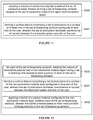
- FIG. 10 depicts an embodiment of a method for manufacturing an electrode system
- FIGS. 11 and 12 depict variations of a portion of a method for manufacturing an electrode system
- FIG. 13 depicts a variation of a method for manufacturing an electrode system
- FIGS. 14A-14C depict specific examples of a method for manufacturing an electrode system
- FIG. 15 depicts an alternative variation of a method for manufacturing an electrode system.
- an embodiment of a system 100 for sensing biometric signals from a body region of a user comprises: a substrate no comprising a reference conductive region 120 and a signal communication region 130 coupled to the reference conductive region, the signal communication region 130 including a set of conductive leads 135 ; a set of biosensing contacts 140 coupled to the set of conductive leads 135 of the signal communication region 130 ; a non-conductive region 150 ensheathing each of the set of biosensing contacts; a first bonding layer 160 that couples the substrate to fabric of a garment; and a second bonding layer 170 coupled to the first bonding layer 160 , wherein the substrate 110 is sealed (e.g., sealed from liquid penetration) between the first bonding layer 160 and the second bonding layer 170 .
- the substrate 110 is sealed (e.g., sealed from liquid penetration) between the first bonding layer 160 and the second bonding layer 170 .
- the system 100 functions to detect one or more biometric signals from one or more body regions of a user who is performing a type of physical activity, wherein processing of the detected biometric signals is used to provide information to the user in substantially near real time, such that the user can gain insights into how to maintain or improve performance of the physical activity in a beneficial manner.
- the biometric electrode system 100 is configured to detect bioelectrical signals generated at a region of the body of a user who is exercising (e.g., performing aerobic exercise, performing anaerobic exercise), wherein a plurality of units of the system 100 can be positioned at multiple body regions of the user, in order to generate a holistic representation of one or more biometric parameters relevant to activity of the user.
- bioelectrical signals detectable, processable, and/or analyzable by the system 100 can include any one or more of: electromyograph (EMG) signals, electrocardiography (ECG) signals, electroencephalograph (EEG) signals, galvanic skin response (GSR), bioelectrical impedance (BIA), and any other suitable bioelectrical signal of the user.
- EMG electromyograph
- ECG electrocardiography
- EEG electroencephalograph
- GSR galvanic skin response
- BIOA bioelectrical impedance
- the system 100 can, however, be configured to detect, process, and/or analyze any other suitable biosignal data of the user, including one or more of: muscle activity data, heart rate data, movement data, respiration data, location data, environmental data (e.g., temperature data, light data, etc.), and any other suitable data.
- the electrode system 100 is configured to be integrated with a garment worn by a user during a period of physical activity, as described in U.S. application Ser. No. 14/541,446, entitled “System and Method for Monitoring Biometric Signals” and filed on 14 Nov. 2014, U.S. application Ser. No. 14/079,629, entitled “Wearable Architecture and Methods for Performance Monitoring, Analysis, and Feedback” and filed on 13 Nov. 2013, and U.S. application Ser. No. 14/079,621, entitled “Wearable Performance Monitoring, Analysis, and Feedback Systems and Methods” and filed on 30 Jan. 2014, each of which is incorporated herein in its entirety by this reference.
- the system 100 is preferably configured to provide a liquid-tight interface (e.g., by way of a seal) in relation to skin of the user, upon coupling of the electrode system 100 to the user, such that sweat or water cannot penetrate the system 100 and interfere with sensitive portions (e.g., conductive leads) of the system 100 during use.
- a liquid-tight interface e.g., by way of a seal
- sensitive portions e.g., conductive leads
- the electrode system 100 is preferably configured to be washable (i.e., hand-washable, machine washable, etc.), to omit any requirement for adhesive coupling to a user using hydrogel coupling media, to be low-maintenance without any need for wetting (e.g., with saline), to provide good surface tack in relation to an interface with skin of the user while the user is in motion, and to be shielded from and reduce any interference generated from the body of the user (e.g., interference due to generation of static, interference in the form of common noise, etc.).
- washable i.e., hand-washable, machine washable, etc.
- the system 100 is preferably configured to be used by a user who is away from a research or clinical setting, such that the user is interfacing with a portion of the system 100 while he or she undergoes periods of physical activity in a natural setting (e.g., at a gym, outdoors, etc.).
- the system 100 can additionally or alternatively be configured to be operated by a user who is in a research setting, a clinical setting, or any other suitable setting.
- Embodiments, variations, and/or examples of the system 100 can be manufactured according to embodiments, variations, and/or examples of the method 200 described in Section 2 below; however, the system 100 can additionally or alternatively be fabricated using any other suitable method.
- the electrode system 100 can be integrated with a wearable garment 102 , including an information transfer inlay 104 configured to facilitate signal transmission from the electrode system 100 , and a portable control module 106 configured to couple to the garment by way of a mount in communication with the information transfer inlay, in order to receive signals from the information transfer inlay 104 .
- the garment 102 is preferably composed of a form-fitting and washable material that is configured to be worn on at least a portion of a user's body. As such, the garment can bias an electrode system 100 , coupled to the garment, against skin of the user, when the garment 102 is worn by the user.
- the garment 102 can thus include a stretchable and/or compressive fabric comprising natural and/or synthetic fibers (e.g., nylon, lycra, polyester, spandex, etc.) to promote coupling (i.e., electrical coupling, mechanical coupling) and/or reduce motion artifacts that could otherwise result from relative motion between the skin of the user and the electrode system 100 .
- the garment 102 can include any one or more of: a top (e.g., shirt, jacket, tank top, etc.), bottom (e.g., shorts, pants, etc.), elbow pad, knee pad, arm sleeve, leg sleeve, socks, undergarment, neck wrap, glove, and any other suitable wearable garment.
- the wearable garment 102 can include one or more slots, pouches, ports, bases, pathways, channels, cradles, or other features by which an information transfer inlay 104 , portable control module 106 , and/or electrode system 100 (described in more detail below) can permanently or removably couple to the wearable garment 102 .
- the garment 102 functions to position one or more units of the electrode system 100 proximal one or more body regions of the user, in order to enable detection of biometric signals from specific body regions of the user as the user is performing a form of physical exercise.
- the garment 102 can thus allow elements to be reliably positioned relative to the body of the user, without involving straps or any other coupling elements typically used to retain an electrode in position at a body region of a user.
- alternative variations of the system 100 can be configured to cooperate with straps and/or any other suitable elements to bias the electrode system 100 against the body of the user reliably.
- the garment 102 can be configured to position the electrode system(s) 100 proximal one or more of: the pectoralisis muscles, the abdominal muscles, the oblique muscles, the trapezius muscles, the rhomboid muscles, the teres major muscles, the latissimus dorsi muscles, the deltoid muscles, the biceps muscles, and the triceps muscles when the garment 102 is worn by the user.
- the pectoralisis muscles the abdominal muscles, the oblique muscles, the trapezius muscles, the rhomboid muscles, the teres major muscles, the latissimus dorsi muscles, the deltoid muscles, the biceps muscles, and the triceps muscles when the garment 102 is worn by the user.
- the garment 102 can be configured to position the electrode system(s) 100 proximal one or more of: the gluteus maximus muscles, the gluteus medius muscles, the vastus lateralis muscles, the gracilis muscles, the semimembranosus muscles, the semitendinosis muscles, the biceps femoris, the quadriceps muscles, the soleus muscles, the gastrocnemius muscles, the rectus femoris muscles, the sartorius muscles, the peroneus longus muscles, and the adductor longus muscles when the garment 102 is worn by the user.
- Variations of the garment 102 can, however, be configured to position units of the electrode system 100 at the body of the user in any other suitable manner.
- the information transfer inlay 104 can include one or more of: conductive, optical, or audible routing between various components.
- the information transfer inlay 104 can electrically, optically or audibly couple one or more components coupled to the garment 102 , in order to facilitate signal transmission between the components.
- the information transfer inlay 104 in relation to the electrode system 100 , can electrically, optically or audibly couple one or more units of the electrode system 100 , and couple the electrode system(s) 100 to the portable control module 106 .
- the information transfer inlay 104 can be integrated with (e.g., bonded into) the fabric of the garment 102 . Additionally or alternatively, the information transfer inlay 104 can be manufactured individually and coupled to the garment 102 after the garment 102 is made. Further, the information transfer inlay 104 can be bonded to any type of garment 102 and need not be specific to a particular apparel type or design. In some variations, a user can customize the location of the information transfer inlay 104 based on the desired locations of one or more electrode systems 100 or one or more portable control modules 106 . In relation to the information transmitted using the information transfer inlay 104 , information can include any one or more of: data, signals, or other information that is transferred via the information transfer inlay 104 . In specific examples, the information can include data, signals, or other information associated with movement, heart rate, respiration, or muscle activity obtained using one or more instances of the electrode system 100 described below; however, the information can additionally or alternatively comprise any other suitable information.
- the garment 102 can be configured to couple to and/or communicate with one or more portable control modules 106 .
- the portable control module(s) 106 can include circuitry for processing signals, storing data, and/or transmitting data, derived from signals generated using the electrode system 100 , to a computing device external to the garment 102 .
- the portable control module 106 can include an attachment interface (e.g., mounting module) by which the portable control module 106 physically couples to the wearable garment 102 and/or by which the portable control module 106 electrically couples to the information transfer inlay 104 .
- the portable control module 106 can permanently or removably couple to the garment 102 when forming an electrical connection with the information transfer inlay 104 .
- coupling the portable control module 106 to the garment 102 may include depositing the portable control module 106 in a mounting pocket of the garment 102 and/or otherwise electrically coupling the portable control module 106 via an interface to the information transfer inlay 104 .
- the mounting pocket includes both physical coupling elements and electrical coupling elements that establish an electrical coupling to the information transfer inlay 104 upon the user physically coupling the portable control module 106 to the mounting pocket.
- a portion of the information transfer inlay 104 can terminate with one or more conductive leads within the mounting pocket of the garment 102 .
- the portable control module 106 can include embodiments, variations, and examples of the control module described in U.S. application Ser. No. 14/541,446, entitled “System and Method for Monitoring Biometric Signals” and filed on 14 Nov. 2014; however, the portable control module 106 can additionally or alternatively include any other suitable control module.
- the electrode system 100 described below can thus be configured to interface with an embodiment of the garment 102 , information transfer inlay 104 , and/or control module 106 described in one or more of: U.S. application Ser. No. 14/541,446, entitled “System and Method for Monitoring Biometric Signals” and filed on 14 Nov. 2014, U.S. application Ser. No. 14/079,629, entitled “Wearable Architecture and Methods for Performance Monitoring, Analysis, and Feedback” and filed on 13 Nov. 2013, and U.S. application Ser. No. 14/079,621, entitled “Wearable Performance Monitoring, Analysis, and Feedback Systems and Methods” and filed on 30 Jan. 2014.
- the electrode system 100 can additionally or alternatively be configured to interface with any other suitable element(s).
- the electrode system 100 includes: a substrate 110 comprising a reference conductive region 120 and a signal communication region 130 coupled to the reference conductive region, the signal communication region 130 including a set of conductive leads 135 ; a set of biosensing contacts 140 coupled to the set of conductive leads 135 of the signal communication region 130 ; a non-conductive region 150 ensheathing each of the set of biosensing contacts; a first bonding layer 160 that couples the substrate to a fabric base; and a second bonding layer 170 coupled to the first bonding layer 160 , wherein the substrate 110 is sealed between the first bonding layer 160 and the second bonding layer 170 .
- one or more portions of the electrode system 100 can be integrated with the information transfer inlay 104 .
- the substrate 110 can be integrated with the information transfer inlay 104 , such that the set of conductive leads 135 is coupled to the first bonding layer 106 , and exposed for coupling to the set of biosensing contacts 140 .
- the second bonding layer 170 can thus provide a set of openings that provide access to the set of conductive leads 135 that are integrated with the information transfer inlay 104 , wherein the set of openings enable coupling of the set of conductive leads 135 to the set of biosensing contacts 140 .
- Alternative variations of integration between the information transfer inlay 106 , the garment 102 , and the electrode system 100 can, however, be configured in any other suitable manner.
- portions of the electrode system 100 can be pre-constructed, in a modular manner, prior to coupling of the electrode system 100 to a garment.
- the set of biosensing contacts 140 and the non-conductive region 150 can be pre-constructed prior to coupling of the set of biosensing contacts 140 to the set of conductive leads 135 , in order to facilitate fabrication of the garment-based biosignal detection system in an efficient manner.
- a non-conductive region 150 coupled to a fabric base 60 , with openings (e.g., laser-cut openings) corresponding to the set of biosensing contacts 140 can be applied to fabric of the garment 102 (e.g., with a polyurethane bonding layer) over a set of conductive leads 135 of a substrate 110 , and the material of the set of biosensing contacts 140 can be applied within the openings (e.g., laser-cut openings), as shown in FIGS. 14A-14C .
- Alternative variations of modularity in the electrode system 100 can, however, be implemented according to requirements of specific applications involving the electrode system 100 .
- the substrate 110 can comprise a reference conductive region 120 and a signal communication region 130 coupled to the reference conductive region, wherein the signal communication region 130 includes a set of conductive leads 135 .
- the substrate functions to facilitate coupling between the set of conductive leads 135 and the set of biosensing contact 140 (described in more detail below), and to enable transmission of signals from the set of conductive leads for downstream processing.
- the substrate is preferably flexible, but can alternatively be rigid or exhibit both flexibility and rigidity (e.g., by using a combination of rigid and flexible materials).
- the substrate no can be composed of a polymer material (e.g., polyamide, polyether ether ketone, etc.).
- the substrate 110 can be composed of one or more of: a rigid polymer material (e.g., a polytetrafluoroethylene based material), a rigid ceramic material (e.g., FR-4, etc.), a rigid metallic material, or a rigid semiconductor material (e.g., silicon with oxidized regions to define conductive and insulating portions of the substrate).
- a rigid polymer material e.g., a polytetrafluoroethylene based material
- a rigid ceramic material e.g., FR-4, etc.
- a rigid metallic material e.g., silicon with oxidized regions to define conductive and insulating portions of the substrate.
- a rigid semiconductor material e.g., silicon with oxidized regions to define conductive and insulating portions of the substrate.
- composite variations of the substrate can include a combination of materials, isolated to specific regions of the substrate no, that provide regions of flexibility and regions of rigidity. Additionally or alternatively, materials used in the substrate 110 can be configured to provide
- the reference region 120 of the substrate 110 functions to serve as a reference “plane”, by which noise and/or any static charge, resulting from motion of the user during performance of a physical activity, can be dissipated.
- the reference region 120 thus functions to facilitate sensing of low amplitude biopotential signals, which can be lost or difficult to pars from environmental noise and/or noise produced by the body of the user.
- the reference region 120 is preferably a layer of the substrate no, wherein the layer can be configured to completely cover the areas directly over the portion of the electrode system 100 where biometrical signals of the user are measured through the set of biosensing contacts 140 .
- the reference region 120 can alternatively not be configured as a layer, and/or can be configured relative to other elements of the electrode system 100 in any other suitable manner.
- the reference region 120 is coupled to the garment 102 , in order to reduce an amount of static due to motion of the garment 102 relative to the set of biosensing contacts 140 of the electrode system 100 ; however, the reference region 120 can alternatively be configured relative to other portions of the system 100 in any other suitable manner.
- signal noise/interference can result from any one or more of: motion of the electrode system 100 relative to the garment 102 , the body of the user (e.g., skin of the user), motion of the electrode system 100 and/or garment relative to additional pieces of clothing worn by the user, and any other suitable source.
- the reference region 120 can thus provide a region (e.g., surface area) across which any static can dissipate before the static develops an interference signal that reduces signal quality downstream, during signal processing.
- the reference region 120 can provide a region of material configured between the set of biosensing contacts 140 and the garment 102 , in order to shield sensitive contact points of the set of biosensing contact 140 from friction, static, and other noise sources that the garment 102 produces relative to other surfaces.
- the reference region 120 can provide an electrostatic barrier between the set of biosensing contacts 140 and the garment 102 .
- additional static and/or noise can be produced due to the garment 102 and additional clothing rubbing together.
- the reference region 120 can dissipate some or all of the resulting static preventing static transfer to other portions of the electrode system 100 .
- At least a portion of the reference region 120 can be connected to the user at a superficial portion of the electrode system 100 (e.g. at a portion of the electrode system 100 away from the biosensing contacts that contact the skin of the user).
- the reference region 120 can additionally or alternatively serve to enable detection and removal of a common-mode component of noise (e.g., 60 Hz noise) from the body of the user, in order to enhance signal processing of biopotential signals received at the set of biosensing contacts 140 .
- the reference region 120 can couple to a reference contact 145 , configured to interface with the body of the user when the garment 102 is worn by the user, wherein the reference contact enables detection of the common-mode component of noise (e.g., 60 Hz noise, noise due to motion of the electrode on the skin of the user).
- the reference contact 145 can be configured between a pair of biosensing contacts, as shown in FIGS.
- the reference contact 145 is equidistant from each biosensing contact in the pair of biosensing contacts.
- the reference contact 145 can enable detection of a component of 60 Hz noise or noise due to motion of the electrode system 100 relative to the user's skin, in order to facilitate downstream signal processing.
- noise present in any detected signals from each of the set of biosensing contacts 140 can be substantially similar to the noise detected within a reference signal by the reference contact 145 .
- the signals received from each of the set of biosensing contacts 140 can be equally related to the reference signal from the reference contact 145 .
- the reference signal that the reference contact 145 detects can be used to filter, subtract, or otherwise eliminate the noise found in the signals from the set of biosensing contacts 140 . Therefore, the reference signal can provide, when used in combination with signals from the set of biosensing contacts 140 , a more accurate reading of any measurement derived from the electrode system 100 .
- the electrode system 100 can cooperate with a reference contact 145 separate from the electrode system 100 , wherein the reference contact 145 is configured to detect a component of 60 Hz noise from a body region of the user (e.g., a body region away from the body region with which the electrode system interfaces) wherein the component of 60 Hz noise is used during signal processing to cancel noise associated with a biosensing contact.
- variations of the substrate 100 can alternatively omit the reference region 120 and/or a reference contact 145 , for instance, due to inclusion of a shared reference region 120 /reference contact 145 for multiple units of the electrode system 100 . Additional variations of the configurations of the reference contact 145 relative to biosensing contacts are shown in FIGS. 3A, 3B, 4, and 5 , and described further below in relation to the set of biosensing contacts 140 .
- the signal communication region 130 is coupled to the reference region 120 of the substrate 110 , and functions to couple the set of biosensing contacts 140 to a set of conductive leads 135 , for signal transmission to other elements in communication with the electrode system 100 .
- the signal communication region 130 is preferably a layer of the substrate 110 , wherein the layer is configured between the layer comprising the reference region 120 and the region defined by the set of biosensing contacts.
- the signal communication region 130 can alternatively not be configured as a layer, and/or can be configured relative to other elements of the electrode system 100 in any other suitable manner.
- the signal communication region 130 includes a set of conductive leads 135 configured to couple to the set of biosensing contacts 140 (described in further detail below), and configured to enable signal transmission from the set of biosensing contacts 140 , through the information transfer inlay 104 , and to a portable control module 106 .
- the set of conductive leads 135 functions to provide signal routing pathways from the set of biosensing contacts 140 , to a portable control module 106 .
- the set of conductive leads 135 is preferably defined at a broad surface of the substrate 110 configured to face skin of the user, when the garment 102 is worn by the user.
- each conductive lead in the set of conductive leads 135 is preferably composed of a metallic material that is electrically conductive; however, the set of conductive leads 135 can additionally or alternatively include any other suitable conductive material (e.g., conductive polymer, etc.).
- the set of conductive leads 135 In coupling the set of conductive leads 135 to the signal communication region 130 of the substrate no, one or more of: an embroidery method, a conductive epoxy, a crimping method, a soldering method, a laser direct structuring approach, a two-shot molding approach, screen printing approach and any other suitable method can be used to couple the set of conductive leads 135 to the signal communication region 130 .
- the set of conductive leads 135 comprises copper leads coupled to the substrate 110 at the signal communication region 130 .
- the set of conductive leads 135 can comprise conductive thread embroidered into a surface of the signal communication region 130 , wherein the conductive thread is initially exposed to enable coupling of the set of biosensing contacts 140 to the conductive thread.
- the conductive thread can have a defined stitching pattern that increases surface area contact of the conductive thread with a biosensing contact of the set of biosensing contacts 140 .
- the stitching pattern can be one or more of: serpentine, zig-zagged, linear, curved, and crossed.
- the conductive thread can additionally or alternatively comprise any other suitable stitching pattern and/or be coupled to the signal communication region 130 of the substrate no in any other suitable manner.
- the substrate 110 can include one or more features that enhance coupling of the set of biosensing contacts 140 to the signal communication region 130 , proximal the set of conductive leads 135 .
- the substrate no includes a plurality of openings 136 , proximal the set of conductive leads 135 , configured to provide additional surface area to increase the peel strength between the set of biosensing contacts 140 and the signal communication region 130 of the substrate no.
- the plurality of openings 136 in the substrate no can provide bonding points between the substrate no and the garment 102 , as described in relation to the bonding layers 160 , 170 of Section 6.2.4 below.
- material of a bonding layer 160 , 170 can flow through the plurality of openings 136 in the substrate no and strengthen a bond between the substrate 110 and the garment 102 .
- the plurality of openings 136 can increase flexibility of the substrate 110 in response to bending and/or torsional stresses experienced during use.
- the substrate 110 can comprise a set of recesses in order to provide additional surface area to increase the peel strength between the set of biosensing contacts 140 and the signal communication region 130 of the substrate 110 .
- the substrate no can comprise an abraded surface in order to provide additional surface area to increase the peel strength between the set of biosensing contacts 140 and the signal communication region 130 of the substrate 110 .
- an adhesive primer can be applied to a surface of the substrate 110 prior to coupling of the set of biosensing contacts 140 to the signal communication region 130 of the substrate.
- the regions of the substrate no proximal the signal communication region 130 can, however, be configured in any other suitable manner to facilitate coupling between the signal communication region 130 and the set of biosensing contacts 140 .
- the set of biosensing contacts 140 functions to detect signals from a body region of the user, when the garment 102 is worn by the user.
- the set of biosensing contacts 140 is configured to be coupled to the set of conductive leads 135 of the signal communication region 130 , and configured to interface with skin of the user when the garment 102 is worn by the user, such that signals from the body of the user can be transmitted through the set of conductive leads 135 for downstream processing, by way of the portable control module 106 .
- the set of biosensing contacts 140 is preferably composed of a conductive polymer material, which can be delivered to the signal communication region 130 of the substrate no in a flow state, and transitioned to a set state (e.g., after curing). Variations of methods for forming the set of biosensing contacts 140 at the substrate no are described further in Section 2 below.
- the set of biosensing contacts 140 is composed of a conductive silicone material, which readily bonds to non-conductive silicone used to form the non-conducting region 150 , as described in further detail below; however, alternative variations of the set of biosensing contacts 140 can alternatively be composed of any other suitable material that readily couples to other related portions of the electrode system 100 .
- the set of biosensing contacts 140 comprises biosensing contacts configured to generate a differential biopotential measurement, to generate a differential biopotential measurement relative to a reference contact, to generate a differential biopotential measurement in cooperation with a reference shield (i.e., for static dissipation), or to generate any suitable number of single ended measurements (e.g., with two non-paired biosensing contacts, with three non-grouped biosensing contacts, etc.).
- Each biosensing contact in the set of biosensing contacts 140 can be identical in morphology to the other biosensing contacts, or alternatively, the set of biosensing contacts 140 can comprise contacts having different morphologies.
- a biosensing contact can be one or more of: circular, ellipsoidal, polygonal, and amorphous in footprint, and can protrude from a surface of the electrode system 100 with a suitable height that allows the biosensing contact to interface with skin of the user during use.
- one or more of the set of biosensing contacts 140 and/or reference contact 145 can be substantially flush with a surface of the non-conductive region 150 (described below), in a manner that still allows for contact with skin of the user during use.
- the set of biosensing contacts 140 can be uniformly spaced across a broad surface of the signal communication region 130 of the substrate no, can be arranged in an array (e.g., rectangular array, circular array, ellipsoidal array, etc.) at the broad surface of the substrate 110 , or can alternatively be arranged in any other suitable configuration.
- each biosensing contact 140 in the set of biosensing contacts 140 has an ellipsoidal footprint, and the set of biosensing contacts 140 is arranged as a uniformly spaced linear array.
- the set of biosensing contacts 140 can include paired biosensing contacts that can enable differential measurement of a biosignal from the body of the user.
- the electrode system 100 can include a pair of biosensing contacts including a first biosensing contact 140 a and a second biosensing contact 140 b .
- the first biosensing contact 140 a can detect a first biopotential signal and the second biosensing contact 140 b can detect a second biopotential signal.
- the electrode system 100 can then provide the first biopotential signal and the second biopotential signal to the portable control module 106 , by way of the information transfer inlay 104 .
- the portable control module 106 and/or other computing device can then use the first biopotential signal and the second biopotential signal to determine a composite signal associated with a differential biopotential measurement (e.g., electrocardiogram or electromyography signal).
- a differential biopotential measurement e.g., electrocardiogram or electromyography signal.
- the set of biosensing contacts 140 ′ can include paired biosensing contacts that can enable differential measurement of a biosignal from the body of the user. Similar to the first set of variations, the electrode system 100 of the second set of variations can include a pair of biosensing contacts including a first biosensing contact 140 a and a second biosensing contact 140 b .
- the first biosensing contact 140 a and the second biosensing contact 140 b can surround (i.e., be adjacent to, oppose each other on different sides of) a reference contact 145 , coupled to the reference region 120 .
- the reference contact 145 can be centered between the first biosensing contact 140 a and the second biosensing contact 140 b and be in communication with the reference region 120 , while the first and the second biosensing contacts 140 a , 140 b communicate with the signal communication region 140 by way of the set of conductive leads 135 .
- the electrode system 100 can then provide the first biopotential signal and the second biopotential signal, as well as a reference signal from the reference contact 145 to the portable control module 106 , by way of the information transfer inlay 104 , to facilitate performance of downstream signal processing.
- the portable control module 106 can sample a signal from the reference contact 145 to facilitate analysis of biopotential signals from the system 100 .
- the set of biosensing contacts 140 can include paired biosensing contacts that can enable differential measurement of a biosignal from the body of the user.
- the electrode system 100 of the second set of variations can include a first biosensing contact 140 a and a second biosensing contact 140 b .
- the first biosensing contact 140 a and the second biosensing contact 140 b can be configured relative to an electrode contact in communication with a reference contact 145 configured to interface with the body of the user, wherein the reference contact 145 may or may not be directly coupled to the substrate no.
- the electrode contact in communication with the reference contact 145 can be configured relative to the first biosensing contact 140 a and the second biosensing contact 140 b in any suitable manner.
- the reference contact 145 can be in communication with multiple units of the electrode system 100 , in facilitating removal of common-mode noise from the body of the user.
- the electrode system 100 can then provide the first biopotential signal and the second biopotential signal, as well as a reference signal from a common reference contact 145 to the portable control module 106 , by way of the information transfer inlay 104 , to facilitate performance of downstream signal processing.
- the portable control module 106 can sample a signal from the reference contact 145 to facilitate analysis of biopotential signals from the system 100 .
- the set of biosensing contacts 140 can include paired biosensing contacts that can enable differential measurement of a biosignal from the body of the user.
- the electrode system 100 of the second set of variations can include a first biosensing contact 140 a and a second biosensing contact 140 b .
- the first biosensing contact 140 a and the second biosensing contact 140 b can be configured relative to a reference contact 145 that interfaces with a reference shield of the substrate no, wherein the reference shield facilitates mitigation of static interference.
- the electrode contact in communication with the reference contact 145 can be configured relative to the first biosensing contact 140 a and the second biosensing contact 140 b in any suitable manner.
- the electrode system 100 can provide the first biopotential signal and the second biopotential signal, to the portable control module 106 , by way of the information transfer inlay 104 , to facilitate performance of downstream signal processing.
- the set of biosensing contacts 140 ′′′′ can include two biosensing contacts, as shown in FIG. 5 , wherein each of the set of biosensing contacts 140 ′′′′ enables generation of a single-ended measurement (e.g., a non-paired measurement).
- the set of biosensing contacts 140 ′′′′ can include three biosensing contacts, as shown in FIG. 6 , wherein each of the set of biosensing contacts 140 ′′′′ enables generation of a single-ended measurement (e.g., a non-paired measurement).
- the electrode system 100 can provide each of the single ended measurements from the biosensing contacts, to the portable control module 106 , by way of the information transfer inlay 104 , to facilitate performance of downstream signal processing.
- the electrode system 100 can have different configurations of the set of biosensing contacts 140 for detecting different types of biopotential signals.
- a subset of the set of biosensing contacts 140 can be configured to capture a particular type of biometric or movement data (e.g., muscle activity, heart activity).
- one or more of the set of biosensing contacts 140 can include different surface areas and/or levels of sensitivity (e.g., based upon conductivity of the material used in the contact) according to features of a particular type of biometric signal.
- the electrode system 100 can include one or more different types of contacts for detecting different types of biometric signals.
- Variations of the set of biosensing contacts 140 can, however, include any suitable combination of any of the above described variations.
- the set of biosensing contacts 140 can be configured relative to a reference contact 145 in any other suitable manner.
- the non-conductive region 150 is configured to ensheath each of the set of biosensing contacts 140 and, if present, a reference contact 145 .
- the non-conductive region 150 thus functions to isolate each of the set of biosensing contacts 140 and/or reference contact 145 , in order to prevent any undesired effects due to bridging of contacts 140 , 145 .
- the non-conductive region 150 can additionally or alternatively function to promote maintenance of coupling between the set of biosensing contacts 140 and the body of the user. Even further, the non-conductive region 150 can function to provide additional mechanical reinforcement, in preventing flexing of the substrate 110 (in variations wherein the substrate 110 is flexible).
- the non-conductive region 150 is preferably configured as a layer of non-conductive material that is directly coupled to at least one of: the signal communication region 130 of the substrate 110 and a fabric patch 60 (in relation to the bonding layers 160 , 170 below), wherein the signal communication region 130 and/or the fabric patch 60 are configured to couple to the garment 102 by way of at least one of the first bonding layer 160 and the second bonding layer 170 .
- openings within the non-conductive region 150 enable coupling of the set of biosensing contacts 140 to the set of conductive leads 135 of the signal communication region 130 .
- the non-conductive region 150 can thus include a set of openings 152 that expose at least a portion of each of the set of biosensing contacts 140 and/or a reference contact 145 , for interfacing with the body region of the user. Additionally or alternatively, in relation to promoting coupling between contacts 140 , 145 and the body the user, the non-conductive region 150 can include a surface feature 157 configured to enhance coupling of the set of biosensing contacts to skin of the user, upon coupling of the electrode system 100 to the user.
- the non-conductive region 150 is preferably composed of a non-conductive polymer material (e.g., silicone) that readily bonds or otherwise couples to the material of the set of biosensing contacts 140 .
- the non-conductive region 150 can be composed of any other suitable insulating material that is processable to isolate each of the set of contacts 140 , 145 , as described in the method 200 of Section 2 below.
- the non-conductive region 150 can be overmolded onto the substrate 110 or directly coupled to another portion of the system 100 (e.g., a fabric base 60 ), and the set of biosensing contacts 140 can be formed (e.g., stenciled) into a corresponding set of openings 152 of the non-conductive region 150 in a multi-step process.
- the set of biosensing contacts 140 can be coupled to the substrate 110
- the non-conductive region 150 can be coupled to the substrate 110 around the set of biosensing contacts 140 in a multi-step process.
- the biosensing contacts 140 and the non-conductive region 150 can, however, be coupled to their respective regions of the substrate no/fabric patch 60 in any other suitable manner.
- the number of openings in the set of openings 152 preferably matches the number, morphology, and configuration of signal conducting contacts 140 , 145 .
- the set of openings 152 of the non-conductive region 150 can include three openings, as shown in FIG. 2B .
- each of the three openings can have an associated reference contact 145 or a biosensing contact of the set of biosensing contacts 140 .
- a first biosensing contact 140 can be coupled within a first opening 152 a of the non-conductive region 150 , a second biosensing contact can fit within a second opening 152 b of the non-conductive region 150 , and a reference contact 145 can fit within a third opening 152 c (e.g., an opening positioned between the first opening 152 a and the second opening 152 b ).
- the openings 152 a , 152 b corresponding to the set of biosensing contacts 140 can provide access to the set of conductive leads 135 of the signal communication region 130 of the substrate no, while the opening 152 c corresponding to a reference contact 145 can provide access to the reference region 120 of the substrate no.
- a first biosensing contact 140 can be coupled within a first opening 152 a of the non-conductive region 150 , a second biosensing contact can fit within a second opening 152 b of the non-conductive region 150 , and a third biosensing contact can fit within a third opening 152 c of the non-conductive regions 150 .
- the set of biosensing contacts 140 includes two biosensing contacts (and the electrode system 100 does not include a reference contact)
- a first biosensing contact 140 can be coupled within a first opening 152 a of the non-conductive region 150
- a second biosensing contact can fit within a second opening 152 b of the non-conductive region 150 .
- the openings 152 a , 152 b corresponding to the set of biosensing contacts 140 can provide access to the set of conductive leads 135 of the signal communication region 130 of the substrate no.
- the non-conductive region 150 can include a surface configured to enhance coupling of the set of biosensing contacts to skin of the user, upon coupling of the electrode system 100 to the user.
- the surface can increase surface tack and/or friction with skin of a user, such that the set of biosensing contacts 140 is substantially retained in position at a desired body region of the user.
- a surface of the non-conductive region 150 that faces the body of the user during use can be composed of a material having high surface tack that limits motion of the signal conducting contacts 140 , 145 during use.
- the non-conductive region 150 can include a non-conductive silicone material that maintains substantially constant contact with a surface of the skin and has a high surface tack, such that the non-conductive region 150 does not slide along a surface of the skin while the user performs an activity.
- the signal conducting contacts 140 , 145 can have a surface feature 157 similar to that of the non-conductive region 150 configured to increase surface tack and/or friction with skin of a user, thereby further promoting coupling of the set of biosensing contacts to skin of the user in a reversible manner, without any adhesive (e.g., hydrogel adhesive material).
- one or more of: the non-conductive region 150 , the reference contact 145 , and each of the set of biosensing contacts 140 can include a surface feature 157 that contacts the skin of the user.
- the surface feature 157 can additionally function to provide more reliable electrical contact between the signal conducting contacts 140 , 145 and skin of the user through hair, sweat, and/or other obstructions that may interfere with maintaining a reliable connection between the electrode system 100 and skin of a user.
- the surface feature 157 can include one or more morphological features and/or textures that engage the user's skin.
- the surface feature 157 can include one or more of: protrusions, bumps, grooves, non-planar surfaces compliant to a body region of the user, and any other suitable surface feature that engage the user's skin and promote maintenance of contact with the user's skin.
- a surface feature 157 at a surface of the non-conductive region 150 can include a movement reduction pattern configured at a peripheral region of the non-conductive region 150 , surrounding the set of biosensing contacts 140 .
- the movement reduction pattern can include at least one morphological feature (e.g., protrusion) that is able to move relative to the non-conductive region 150 as the fabric of the garment 102 is strained and stressed as a result of motion of the user.
- morphological feature e.g., protrusion
- the surface feature 157 can include a plurality of non-conductive dot protrusions arranged in an array about the set of biosensing contacts 140 , which are able to move relative to each other in relation to stretching of the fabric base of the garment 102 .
- the dot protrusion features can function to reduce motion or movement of the electrode system 100 relative to the user during use.
- any other suitable surface feature 157 can be positioned about the signal conducting contacts 140 , 145 .
- the surface feature(s) 157 can include one or more patterns (e.g., linear patterns) of non-conductive material, or other shaped extensions from the fabric that interact with the skin of the user to prevent movement of the area of the garment corresponding to the biometric electrode.
- patterns e.g., linear patterns
- the reference contact 145 and each of the set of biosensing contacts 140 can include a plurality of protrusions 157 ′ at a surface of the contact that comes into contact with the skin.
- the non-conductive region 150 can include or be coupled to a feature that either functions as a barrier against bridging of contacts 140 , 145 (e.g., by sweat generated during an activity of the user), or that functions to divert any present fluid in a controlled manner, to prevent bridging of contacts.
- the non-conductive region 150 can be coupled to a barrier 158 of a porous material (e.g., porous foam) configured between the reference contact 145 and each of the set of biosensing contacts 140 , wherein the barrier 158 prevents sweat or other moisture from bridging the contacts 140 , 145 and causing a low resistance path between the contacts 140 , 145 .
- a porous material e.g., porous foam
- the porous material of the barrier 158 can readily absorb excess moisture that could otherwise create a secondary conductive path between the contacts 140 , 145 in an undesired manner.
- the barrier 158 can additionally or alternatively function to divert any fluid in proximity to the contacts 140 , 145 , away from the contacts 140 , 145 by providing a low resistance fluid path away from the contacts 140 , 145 .
- the first bonding layer 160 is configured to couple the substrate 110 (e.g., integrated with the information transfer inlay 104 ) to fabric of a garment 102 , and functions to form a first portion of a bonding assembly that seals sensitive portions of the substrate 110 (e.g., integrated with the information transfer inlay 104 ) from damage or shorting that could otherwise result from fluid reaching the substrate 110 .
- the first bonding layer 160 can facilitate isolation of one or more of: the reference region 120 of the substrate 110 , the signal communication region 130 of the substrate 110 , and the set of conductive leads 135 from fluid (e.g., sweat) associated with a period of physical activity performed by the user.
- the first bonding layer 160 can couple a flexible variation of the substrate no to fabric of the garment 102 , thus forming a first portion of an assembly that seals the substrate 110 from moisture.
- the first bonding layer 160 is preferably composed of a hydrophobic material that is impermeable to fluids; however, the material of the first bonding layer 160 can alternatively be non-hydrophobic while still being impermeable to fluids.
- the first bonding layer 160 comprises a polyurethane film that can be thermally bonded to the second bonding layer 170 and/or other elements of the system 100 ; however, variations of the first bonding layer 160 can be composed of any other suitable material (e.g., polymeric material) that is bondable to other elements of the system 100 in any other suitable manner (e.g., by adhesive bonding, etc.).
- the first and the second bonding layers 160 , 170 are preferably composed of identical materials; however, in alternative variations, the first and the second bonding layers 160 , 170 can alternatively be composed of different materials.
- the second bonding layer 170 is configured to couple to at least a portion of the first bonding layer 160 , such that the substrate 110 is sealed between the first bonding layer 160 and the second bonding layer 170 .
- the second bonding layer 170 can be coupled to the first bonding layer 160 at a peripheral region of the first bonding layer, to seal the substrate 110 within the bonding layers 160 , 170 .
- a first surface of the second bonding layer 170 is configured to couple to the substrate 110 and the first bonding layer 160
- a second surface of the second bonding layer 170 that opposes the first surface is configured to couple to a fabric patch 60 , to which the non-conductive region 150 is coupled.
- openings in the fabric patch 60 and the second bonding layer 170 can provide access to the set of conductive leads 135 of the substrate 110 , when the material of the signal conducting contacts 140 , 145 is transmitted toward the set of conductive leads 135 .
- the second bonding layer 170 , the fabric patch 60 , and the non-conductive region 150 can thus comprise an initial assembly that is coupled to the first bonding layer 160 at the garment. Then, the signal conducting contacts 140 , 145 can be coupled to the set of conductive leads 135 by way of the set of openings 152 of the non-conductive region 150 that pass through the fabric patch 60 and the second bonding layer 170 .
- fabric that does not interfere with signal conduction by the signal conducting contacts 140 , 145 can be provided in any suitable manner, thus providing material that increases comfort when the electrode system 100 interfaces with the user.
- similar variations may omit fabric, such that no fabric layer covers the second bonding layer 170 .
- the second bonding layer 170 is preferably composed of a hydrophobic material that is impermeable to fluids; however, the material of the second bonding layer 170 can alternatively be non-hydrophobic while still being impermeable to fluids.
- the second bonding layer 170 comprises a polyurethane film that can be thermally bonded to the first bonding layer 160 and/or other elements of the system 100 ; however, variations of the second bonding layer 170 can be composed of any other suitable material (e.g., polymeric material) that is bondable to other elements of the system 100 in any other suitable manner (e.g., by adhesive bonding, etc.).
- the first and the second bonding layers 160 , 170 are preferably composed of identical materials; however, in alternative variations, the first and the second bonding layers 160 , 170 can alternatively be composed of different materials.
- the substrate 110 is bonded to the fabric base 60 of the garment 102 using a first bonding layer 160 comprising polyurethane film.
- the first bonding layer 160 is applied to the substrate 110 to heat press the substrate 110 against the fabric of the garment 102 , and a second bonding layer 170 composed of polyurethane film is coupled over the substrate 110 to further seal the substrate 110 between two bonding layers 160 , 170 in relation to the garment 102 .
- the second bonding layer 170 in the specific example includes cutouts corresponding to the signal conducting contacts 140 , 145 , such that the reference contact and biosensing contact surfaces are exposed through the second bonding layer 170 , thus enabling contact between the contacts 140 , 145 and the skin of a user.
- the first and the second bonding layers 160 , 170 in the specific example encase the non-conductive region 150 and other components of the electrode system 100 (i.e., the substrate 110 ) while permitting the reference contact 145 and the set of biosensing contacts 140 to be exposed through the second bonding layer 170 and to interface with the skin of a user.
- the system 100 can include any other suitable elements configured to enhance coupling of electrode elements to a body region of a user, to dissipate static, to enable removal of common-mode noise from the body of a user, to prevent moisture damage to elements of the system 100 , and/or to facilitate manufacturing of the system 100 .
- any other suitable elements configured to enhance coupling of electrode elements to a body region of a user, to dissipate static, to enable removal of common-mode noise from the body of a user, to prevent moisture damage to elements of the system 100 , and/or to facilitate manufacturing of the system 100 .
- an embodiment of a method 200 for manufacturing an electrode system comprises: providing a substrate comprising a reference layer and a signal communication layer coupled (e.g., mechanically coupled, electrically coupled) to the reference layer, the signal communication layer including a set of conductive leads S 210 ; coupling a volume of conductive polymer to each of the set of conductive leads, thereby forming a set of biosensing contacts coupled to the set of conductive leads of the signal communication region S 220 ; for each of the set of biosensing contacts, isolating the volume of conductive polymer with a non-conductive material layer having a set of openings that expose at least a portion of each of the set of biosensing contacts S 230 ; coupling a first bonding layer between the substrate and fabric of a garment S 240 ; and coupling a second bonding layer to the first bonding layer at a peripheral region of the first bonding layer, thereby sealing the substrate between the first bonding layer and the second bonding
- the method 200 functions to produce an electrode system that is coupleable to a garment intended to be worn by a user while the user performs a physical activity.
- the method 200 functions to produce an electrode system that is resistant to damage by fluid associated with an activity performed by an individual, and that maintains contact with the user as the user performs the activity.
- the method 200 can provide an electrode system configured to detect one or more of: electromyograph (EMG) signals, electrocardiography (ECG) signals, electroencephalograph (EEG) signals, galvanic skin response (GSR) signals, bioelectric impedance (BIA) and any other suitable biopotential signal of the user.
- EMG electromyograph
- ECG electrocardiography
- EEG electroencephalograph
- GSR galvanic skin response
- BIOA bioelectric impedance
- the method 200 is preferably implemented at least in part at an embodiment of the system 100 described in Section 6 above; however, the method 200 can alternatively be implemented at any other suitable system for detection and processing of biometric signals from a user who is performing a
- the method 200 can produce an embodiment, variation, or example of the electrode system 100 described in Section 6 above; however, in other embodiments, sub-portions of the method 200 can be adapted to manufacturing portions of any other suitable electrode system
- Blocks of the method 200 can be performed in any suitable order, variations of which are described below.
- Block S 210 recites: providing a substrate comprising a reference layer and a signal communication layer coupled (e.g., mechanically coupled, electrically coupled) to the reference layer, the signal communication layer including a set of conductive leads, which functions to provide a first portion of the electrode system that provides coupling regions for a set of biosensing contacts.
- the substrate is preferably the substrate described in Section 6.2.1 above, which in some variations can omit the reference layer; however, in other variations, the substrate can comprise any other suitable substrate having conductive leads intended to interface with a set of biosensing contacts.
- Block S 220 recites: coupling a volume of conductive polymer to each of the set of conductive leads, thereby forming a set of biosensing contacts coupled to the set of conductive leads of the signal communication region of the substrate.
- Block S 220 can further include forming at least one reference contact configured to couple to the reference region of the substrate, in variations wherein the electrode system includes a reference contact.
- the volume of conductive polymer comprises a conductive silicone material that is compliant to some degree, impermeable to fluid, electrically conductive, and readily bondable to other elements of the electrode system; however, the volume of conductive polymer can alternatively comprise any other suitable material (e.g., polymeric material, composite material, conductive material, etc.).
- Block S 220 can comprise injection molding volumes of the conductive polymer in a flow state onto the signal communication region of the substrate, proximal the set of conductive leads, and transitioning the conductive polymer to a set state that maintains the morphological configurations of the set of biosensing contacts.
- Block S 220 can comprise printing (e.g., with a stencil) volumes of the conductive polymer in a flow state onto the signal communication region of the substrate, proximal the set of conductive leads, and transitioning the conductive polymer to a set state that maintains the morphological configurations of the set of biosensing contacts.
- Block S 220 can include one or more of: screen printing processes, stenciling processes, ink-jet printing processes to couple the set of biosensing contacts to the set of conductive leads of the substrate.
- Block S 110 can include providing a substrate with one or more of: a set of openings, a set of recesses, an abraded surface, and an adhesive primer, to enhance coupling of the conductive polymer to the desired region(s) of the substrate in Block S 220 .
- Block S 220 can include coupling a cured piece of the conductive polymer to at least one of the set of conductive leads, for instance, using a conductive adhesive material for coupling.
- volumes of the conductive polymer can be printed or otherwise applied onto transfer paper to form a set of conductive geometries (e.g., set conductive polymer), after which the conductive geometries are positioned at suitable locations of the substrate and coupled to the substrate (e.g., using a thermal bonding process). Finally, the transfer paper can be removed.
- the transfer paper surface can have a texture that provides a surface texture at each of the set of contacts.
- Block S 220 can further include forming a surface feature comprising a set of protrusions at a surface of at least one of the set of biosensing contacts configured to face skin of the user, wherein the set of protrusions facilitates maintenance of contact between the electrode system and skin of the user S 221 .
- the set of protrusions can be formed using one or more of: a molding process, a casting process, a printing process, and any other suitable process.
- Block S 220 can, however, include any other steps associated with formation of features described in Section 6.2.2 above.
- variations of the method 200 can comprise coupling the volumes of the conductive polymer to the set of conductive leads prior to and/or after coupling of the non-conductive region to a fabric patch or fabric of the garment in Block S 230 , which is described further in Section 2.1 below.
- Block S 230 recites: for each of the set of biosensing contacts, isolating the volume of conductive polymer with a non-conductive material layer having a set of openings that expose at least a portion of each of the set of biosensing contacts.
- Block S 230 functions to form a barrier between each contact of the electrode system, in order to prevent bridging of contacts in an undesired manner.
- Block S 230 can comprise coupling the non-conductive material of the material layer directly to a fabric patch, wherein the fabric patch is backed with a bonding layer configured to interface with a first bonding layer coupled to a backside of the substrate.
- the first bonding layer can couple the substrate to a garment, and the bonding layer coupled to the fabric patch can seal the substrate between two bonding layers, as described above.
- the first bonding layer can couple the substrate to a garment and a second bonding layer in a manner that encapsulates the substrate, while enabling coupling of the second bonding layer to a fabric layer (e.g., for user comfort).
- a set of openings in the second bonding layer is configured to provide access to the signal conducting region of the substrate for coupling of the set of biosensing contacts to the set of conductive leads of the signal conducting region.
- the substrate 110 is entirely sealed (e.g., from liquid penetration).
- Block S 230 can comprise coupling (e.g., heat pressing, using an adhesive, using a chemical bond, etc.) the non-conductive material layer to a fabric patch which is backed with a bonding layer (e.g., polyurethane film), and cutting openings through the non-conductive material layer, the fabric patch, and the bonding layer in a configuration that corresponds to the set of biosensing contacts of Block S 220 .
- a bonding layer e.g., polyurethane film
- the conductive polymer of the contacts of Block S 220 can be applied within the openings of the non-conductive region, to ultimately couple to the set of conductive leads of the substrate.
- Block S 230 can comprise coupling the non-conductive material layer directly to the substrate (e.g., using an adhesive primer, etc.) or any other suitable portion of the electrode system, that allows sensitive portions of the substrate to be sealed between bonding layers.
- the conductive polymer material of Block S 220 can be coupled to the set of conductive leads of the substrate in a controlled manner, and the non-conductive material layer can be coupled (e.g., over-molded, applied in a cured state, etc.) to regions of the substrate around each of the volumes of conductive polymer, to isolate each of the set of contacts.
- Variations of Block S 230 can, however, be implemented in any other suitable manner.
- the non-conductive material layer is preferably composed of a material that readily couples with the polymer material of the set of biosensing contacts of Block S 220 .
- the non-conductive material layer is composed of a non-conductive silicone material.
- the non-conductive material layer can alternatively be composed of any other suitable material having low conductivity (e.g., insulating properties), that is otherwise configured to couple to the conductive polymer of Block S 220 in any other suitable manner.
- Block S 230 can comprise over-molding a volume of the non-conductive material layer in a flow state onto at least one of the fabric patch and the substrate, and transitioning the non-conductive material to a set state.
- Block S 230 can comprise printing (e.g., 3D printing) the non-conductive material layer in a flow state onto at least one of the fabric patch and the substrate, and transitioning the non-conductive material to a set state.
- Block S 230 can include one or more of: screen printing processes, stenciling processes, ink-jet printing processes, and any other suitable processes to couple the non-conductive material to at least one of the fabric patch and the substrate.
- Block S 110 can include providing a substrate with one or more of: a set of openings, a set of recesses, an abraded surface, and an adhesive primer, to enhance coupling of the non-conductive material to the desired region(s) of the substrate in Block S 230 .
- Block S 230 can include coupling a cured piece of the non-conductive material layer to at least one of the fabric patch and the substrate (e.g., with an adhesive).
- Block S 230 can further include: forming a surface feature comprising a set of protrusions at a surface of the non-conductive material layer configured to face skin of the user, wherein the set of protrusions facilitates maintenance of contact between the electrode system and skin of the user S 231 .
- the set of protrusions can be formed using one or more of: a molding process, a casting process, a printing process, and any other suitable process.
- Block S 230 can include: applying a barrier of a porous material (e.g., porous foam) configured at the non-conductive material layer, between each of the set of biosensing contacts, wherein the barrier prevents sweat or other moisture from bridging contacts of the set of biosensing contacts S 232 .
- the barrier can be formed using one or more of: a molding process, a casting process, a printing process, an adhesive application process, and any other suitable process.
- Block S 230 can, however, include any other steps associated with formation of features described in Section 6.2.3 above.
- variations of the method 200 can comprise coupling of the non-conductive region to a fabric patch or fabric of the garment in Block S 230 , after which volumes of the conductive polymer, associated with Block S 220 , are applied within a set of openings of the non-conductive region, which is described further in Section 2.1 below.
- Blocks S 220 and S 230 can be performed in any suitable order.
- Block S 240 recites: coupling a first bonding layer between the substrate and fabric of a garment, which functions to couple the substrate to fabric of the garment. Block S 240 further functions to form a first portion of a bonding region that seals sensitive portions of the substrate and protects the substrate from moisture.
- the first bonding layer is preferably composed of a hydrophobic material that is impermeable to fluids; however, the material of the first bonding layer used in Block S 240 can alternatively be non-hydrophobic while still being impermeable to fluids.
- Block S 240 comprises thermally bonding polyurethane film between the substrate and fabric of the garment, wherein the polyurethane film can be thermally bonded to the second bonding layer of Block S 250 and/or other elements of the system; however, variations of Block S 240 can comprise coupling a first bonding layer composed of any other suitable material (e.g., polymeric material) that is bondable to other elements of the system in any other suitable manner (e.g., by adhesive bonding, etc.).
- suitable material e.g., polymeric material
- the first and the second bonding layers are preferably composed of identical materials; however, in alternative variations, the first and the second bonding layers can alternatively be composed of different materials.
- Block S 240 can be performed simultaneously with one or more of: Blocks S 210 , S 220 , S 230 , and S 250 , for instance, in relation to coupling processes involving thermal bonding.
- Block S 240 can be performed prior to or after any of the blocks of the method 200 , as appropriate for any other suitable method of coupling the first bonding layer between the substrate and fabric of the garment.
- Block S 250 recites: coupling a second bonding layer to the first bonding layer at a peripheral region of the first bonding layer, thereby sealing the substrate between the first bonding layer and the second bonding layer, while maintaining exposure of the portion of each of the set of biosensing contacts.
- Block S 250 functions to form a second portion of a bonding region that seals sensitive portions of the substrate and protects the substrate from moisture.
- the second bonding layer is preferably composed of a hydrophobic material that is impermeable to fluids; however, the material of the second bonding layer used in Block S 250 can alternatively be non-hydrophobic while still being impermeable to fluids.
- the first and the second bonding layers are preferably composed of identical materials; however, in alternative variations, the first and the second bonding layers can alternatively be composed of different materials.
- Block S 250 comprises thermally bonding polyurethane film to a first broad surface of a fabric patch, wherein the non-conductive material layer is coupled to a second broad surface of the fabric patch.
- Block S 250 further comprises cutting a set of openings (i.e., corresponding to the set of biosensing contacts) through the non-conductive material layer, the fabric patch, and the second bonding layer, and coupling the second bonding layer to the first bonding layer using a thermal bonding process, thereby sealing the substrate between the bonding layers.
- the assembly comprising non-conductive material layer, the fabric patch, and the second bonding layer can be applied over the substrate, with the set of conductive leads exposed through the openings, and the conductive polymer material can be coupled within the set of openings to the set of conductive leads in Block S 220 .
- the second bonding layer can be coupled to the first bonding layer at a peripheral region of the first bonding layer, in a manner that seals at least a portion of the substrate between the bonding layers.
- variations of Block S 250 can comprise coupling a second bonding layer composed of any other suitable material (e.g., polymeric material) to the first bonding layer and/or any other suitable elements of the system in any other suitable manner (e.g., by adhesive bonding, etc.).
- the second bonding layer can comprise or otherwise be coupled a fabric layer configured to interface with skin of the user, thereby enhancing comfort of the system 100 while the system 100 interfaces with the body of the user.
- the fabric layer-second bonding layer assembly can include a set of openings, as described in relation to the system 100 above and variations of manufacture below, wherein the set of openings provide access to a set of conductive leads for coupling to a set of biosensing contacts.
- the method 200 ′ can include: providing a substrate comprising a set of conductive leads S 210 ′; coupling the substrate to fabric of a garment with a first bonding layer S 240 ′; forming an assembly comprising a non-conductive material layer coupled to a first broad surface of a fabric patch and a second bonding layer coupled to the second broad surface of the fabric patch S 250 ′, wherein Block S 250 ′ includes cutting a set of openings through the assembly; sealing the substrate within the first bonding layer and the second bonding layer S 252 ′, with at least a portion of the set of conductive leads exposed through the set of openings; and coupling a volume of conductive polymer to each of the set of conductive leads, thereby forming a set of biosensing contacts coupled to the set of conductive leads and to the non-conductive material layer S 220 ′.
- a substrate comprising a set of conductive copper leads can be coupled to fabric of a garment with a first bonding layer.
- an assembly comprising a polyurethane-backed fabric patch (i.e., a fabric patch with a second bonding layer), coupled to a non-conductive silicone layer and having a set of openings through the assembly can be coupled to the first bonding layer, thereby sealing the substrate, while leaving the set of conductive copper leads exposed through the set of openings of the assembly.
- conductive silicone material can be stenciled into the set of openings, thereby coupling the conductive polymer to the set of conductive leads and to the non-conductive silicone layer, to form the set of biosensing contacts.
- a substrate comprising a set of conductive copper leads can be coupled to fabric of a garment with a first bonding layer.
- an assembly comprising a polyurethane-backed fabric patch (i.e., a fabric patch with a second bonding layer), coupled to a non-conductive silicone layer and having a set of openings through the assembly can be formed, wherein the non-conductive silicone layer is abraded (e.g., with sand paper) and wiped clean to remove debris (e.g., with alcohol).
- the assembly is then coupled to the first bonding layer, thereby sealing the substrate, while leaving the set of conductive copper leads exposed through the set of openings of the assembly.
- a primer can be applied to the abraded non-conductive silicone layer and edges of the set of openings.
- conductive silicone material can be stenciled into the set of openings and pressed with heat, thereby coupling the conductive polymer to the set of conductive leads and to the non-conductive silicone layer, to form the set of biosensing contacts.
- a substrate comprising a set of conductive copper leads can be coupled to fabric of a garment with a first bonding layer. Then, an assembly comprising a polyurethane-backed fabric patch (i.e., a fabric patch with a second bonding layer) and having a set of openings through the assembly can be formed. In this specific application, the assembly is then coupled to the first bonding layer, thereby sealing the substrate, while leaving the set of conductive copper leads exposed through the set of openings of the assembly. Next, a primer can be applied to the edges of the set of openings. Finally, conductive silicone material can be stenciled into the set of openings and pressed with heat, thereby coupling the conductive polymer to the set of conductive leads and to the non-conductive silicone layer, to form the set of biosensing contacts.
- a polyurethane-backed fabric patch i.e., a fabric patch with a second bonding layer
- an alternative variation of the method 200 ′′ can comprise: providing a substrate comprising a set of conductive leads S 210 ′′; injection molding a volume of conductive polymer at each of the set of conductive leads, thereby forming a set of biosensing contacts coupled to the set of conductive leads S 220 ′′; for each of the set of biosensing contacts, isolating the volume of conductive polymer with a non-conductive material layer having a set of openings that expose at least a portion of each of the set of biosensing contacts, using an over-molding process S 230 ′′; coupling a first bonding layer between the substrate and fabric of a garment S 240 ′′; and coupling a second bonding layer to the first bonding layer at a peripheral region of the first bonding layer, thereby sealing the substrate between the first bonding layer and the second bonding layer, while maintaining exposure of the portion of each of the set of biosensing contacts S 250 ′′.
- a non-conductive region can be formed, for subsequent coupling to material of the set of biosensing contacts.
- the non-conductive region can comprise one or more of: a fabric material, a non-conductive material (e.g., polymer material), and any other suitable material that couples to the material of the set of biosensing contacts.
- the non-conductive region comprises a fabric layer with a coating of non-conductive silicone coupled to the fabric layer, wherein the non-conductive region is configured to provide a high friction (e.g., non-slip) surface upon interfacing with skin of the user.
- the non-conductive region can maintain positioning of the set of biosensing contacts at the skin of the user, and prevent noise from being generated due to motion of the system 100 relative to skin of the user.
- a set of openings can be formed in the non-conductive region, wherein the set of openings corresponds to a desired configuration of the set of biosensing contacts, in correspondence with the set of conductive leads, to which the set of biosensing contacts is coupled.
- forming the set of openings can comprise a cutting method (e.g., laser cutting, punching, etc.); however any other suitable method of forming openings can be used.
- variations of the alternative method can involve mass production of non-conductive regions for multiple electrode systems, wherein the non-conductive regions can be separated from each other at subsequent processing stages, thereby increasing efficiency in handling during manufacture of the electrode system.
- the non-conductive region can then be positioned (e.g., with positioning/alignment features) into an injection molding apparatus, after which conductive polymer material (e.g., conductive silicone, conductive elastomer, etc.) of the set of biosensing contacts is injected into the set of openings of the non-conductive region.
- conductive polymer material e.g., conductive silicone, conductive elastomer, etc.
- the conductive polymer material can then be cured (e.g., by heating, etc.) to increase durability.
- one or more primers can be used to coupling the conductive polymer material to the non-conductive material.
- any other suitable method of depositing the conductive polymer material e.g., compression molding, screen printing, mask printing, etc.
- a recessed region at a “backside” of each of the set of biosensing contacts can be formed (e.g., based upon a feature of the mold used in the molding process), in order to facilitate subsequent bonding of the set of biosensing contacts to the set of conductive leads.
- a first bonding layer having a set of openings corresponding to the set of biosensing contacts can be coupled to the non-conductive region (e.g., based upon a thermal bonding process, based upon a spraying-application process, based upon any other suitable process).
- a conductive adhesive material can be applied to each of the set of biosensing contacts, for coupling of the set of biosensing contacts to the set of conductive leads.
- a volume of uncured conductive silicone can be applied into a recess at the “backside” of each biosensing contact, and/or to each conductive lead, and the set of biosensing contacts can thus be coupled to the set of conductive leads (e.g., using a thermal bonding process, using pressure, etc.)
- Embodiments, variations, and examples of the method 200 can thus generate an electrode system that is thinner, lighter, and resource efficient, using a process that is less labor-intensive.
- Variations of the system 100 and method 200 include any combination or permutation of the described components and processes.
- various processes of the preferred method can be embodied and/or implemented at least in part as a machine configured to receive a computer-readable medium storing computer-readable instructions.
- the instructions are preferably executed by computer-executable components preferably integrated with a system and one or more portions of the control module 155 and/or a processor.
- the computer-readable medium can be stored on any suitable computer readable media such as RAMs, ROMs, flash memory, EEPROMs, optical devices (CD or DVD), hard drives, floppy drives, or any suitable device.
- the computer-executable component is preferably a general or application specific processor, but any suitable dedicated hardware device or hardware/firmware combination device can additionally or alternatively execute the instructions.
- each block in the flowchart or block diagrams may represent a module, segment, step, or portion of code, which comprises one or more executable instructions for implementing the specified logical function(s).
- the functions noted in the block can occur out of the order noted in the FIGURES. For example, two blocks shown in succession may, in fact, be executed substantially concurrently, or the blocks may sometimes be executed in the reverse order, depending upon the functionality involved.
Landscapes
- Health & Medical Sciences (AREA)
- Life Sciences & Earth Sciences (AREA)
- Engineering & Computer Science (AREA)
- Surgery (AREA)
- Animal Behavior & Ethology (AREA)
- Veterinary Medicine (AREA)
- Public Health (AREA)
- Physics & Mathematics (AREA)
- General Health & Medical Sciences (AREA)
- Biophysics (AREA)
- Pathology (AREA)
- Biomedical Technology (AREA)
- Heart & Thoracic Surgery (AREA)
- Medical Informatics (AREA)
- Molecular Biology (AREA)
- Signal Processing (AREA)
- Computer Vision & Pattern Recognition (AREA)
- Artificial Intelligence (AREA)
- Psychiatry (AREA)
- Physiology (AREA)
- Measurement And Recording Of Electrical Phenomena And Electrical Characteristics Of The Living Body (AREA)
Abstract
Description
Claims (18)
Priority Applications (2)
| Application Number | Priority Date | Filing Date | Title |
|---|---|---|---|
| US14/699,730 US10617354B2 (en) | 2014-04-29 | 2015-04-29 | Biometric electrode system and method of manufacture |
| US16/809,439 US20200397372A1 (en) | 2014-04-29 | 2020-03-04 | Biometric Electrode System and Method of Manufacture |
Applications Claiming Priority (3)
| Application Number | Priority Date | Filing Date | Title |
|---|---|---|---|
| US201461985874P | 2014-04-29 | 2014-04-29 | |
| US201462044683P | 2014-09-02 | 2014-09-02 | |
| US14/699,730 US10617354B2 (en) | 2014-04-29 | 2015-04-29 | Biometric electrode system and method of manufacture |
Related Child Applications (1)
| Application Number | Title | Priority Date | Filing Date |
|---|---|---|---|
| US16/809,439 Continuation US20200397372A1 (en) | 2014-04-29 | 2020-03-04 | Biometric Electrode System and Method of Manufacture |
Publications (2)
| Publication Number | Publication Date |
|---|---|
| US20150305677A1 US20150305677A1 (en) | 2015-10-29 |
| US10617354B2 true US10617354B2 (en) | 2020-04-14 |
Family
ID=54333641
Family Applications (2)
| Application Number | Title | Priority Date | Filing Date |
|---|---|---|---|
| US14/699,730 Expired - Fee Related US10617354B2 (en) | 2014-04-29 | 2015-04-29 | Biometric electrode system and method of manufacture |
| US16/809,439 Abandoned US20200397372A1 (en) | 2014-04-29 | 2020-03-04 | Biometric Electrode System and Method of Manufacture |
Family Applications After (1)
| Application Number | Title | Priority Date | Filing Date |
|---|---|---|---|
| US16/809,439 Abandoned US20200397372A1 (en) | 2014-04-29 | 2020-03-04 | Biometric Electrode System and Method of Manufacture |
Country Status (1)
| Country | Link |
|---|---|
| US (2) | US10617354B2 (en) |
Cited By (8)
| Publication number | Priority date | Publication date | Assignee | Title |
|---|---|---|---|---|
| US20220175292A1 (en) * | 2017-03-01 | 2022-06-09 | CB Innovations, LLC | Screen Printed Electrodes For An Electrocardiogram Article |
| US12178580B2 (en) | 2019-12-23 | 2024-12-31 | Alimetry Limited | Electrode patch and connection system |
| US12295746B2 (en) | 2020-10-16 | 2025-05-13 | Whoop, Inc. | Adjustable strap for wearable monitor |
| US12318314B2 (en) | 2022-06-03 | 2025-06-03 | JSG IP Ventures, LLC | System and methods for residual limbs of amputees |
| US12324754B1 (en) | 2024-08-20 | 2025-06-10 | JSG IP Ventures, LLC | System for residual limbs of amputees |
| US12329969B1 (en) | 2024-08-20 | 2025-06-17 | JSG IP Ventures, LLC | System and methods for residual limbs of amputees |
| US12337177B1 (en) | 2024-08-20 | 2025-06-24 | JSG IP Ventures, LLC | Method for residual limbs of amputees |
| US12521069B2 (en) | 2021-12-23 | 2026-01-13 | Marani Health, Inc. | System for acquisition and analysis of maternal and/or fetal physiological signals |
Families Citing this family (14)
| Publication number | Priority date | Publication date | Assignee | Title |
|---|---|---|---|---|
| US11071498B2 (en) | 2013-09-17 | 2021-07-27 | Medibotics Llc | Smart clothing with inertial, strain, and electromyographic sensors for human motion capture |
| US11892286B2 (en) | 2013-09-17 | 2024-02-06 | Medibotics Llc | Motion recognition clothing [TM] with an electroconductive mesh |
| US11304628B2 (en) | 2013-09-17 | 2022-04-19 | Medibotics Llc | Smart clothing with dual inertial sensors and dual stretch sensors for human motion capture |
| US12527521B2 (en) | 2013-09-17 | 2026-01-20 | Medibotics Llc | Motion recognition clothing™ with inertial sensors and electrical or optical strain sensors |
| CN107111683B (en) * | 2014-11-19 | 2021-07-23 | 耐克创新有限合伙公司 | Sports belt with removable modules |
| US20160278702A1 (en) * | 2015-03-23 | 2016-09-29 | Zentan Technology Co., Ltd. | Physiological signal monitoring belt |
| US10842205B2 (en) * | 2016-10-20 | 2020-11-24 | Nike, Inc. | Apparel thermo-regulatory system |
| WO2018082362A1 (en) * | 2016-11-03 | 2018-05-11 | 成都柔电云科科技有限公司 | Method for fabricating epidermal electrode |
| CN110678120B (en) | 2017-05-29 | 2022-09-30 | 东洋纺株式会社 | Clothing for measuring physiological information |
| US12329217B2 (en) * | 2017-06-20 | 2025-06-17 | Innovation Ventures IP at UKHS, LLC. | Stress test garment and method of use |
| WO2019176839A1 (en) * | 2018-03-16 | 2019-09-19 | 日東電工株式会社 | Biosensor laminate and biosensor |
| JP7161963B2 (en) * | 2018-03-16 | 2022-10-27 | 日東電工株式会社 | Laminate for biosensor and biosensor |
| GB2592694B (en) * | 2020-06-18 | 2022-04-06 | Prevayl Innovations Ltd | Electronics module |
| NO347342B1 (en) * | 2021-09-16 | 2023-09-25 | Luzmon Medical As | An electrode pad for electro-stimulation and method of manufacturing same |
Citations (67)
| Publication number | Priority date | Publication date | Assignee | Title |
|---|---|---|---|---|
| US3534727A (en) | 1967-03-24 | 1970-10-20 | Nasa | Biomedical electrode arrangement |
| US3973099A (en) | 1974-11-11 | 1976-08-03 | American Micro-Systems, Inc. | Push button switch for electronic watch |
| US4400341A (en) | 1980-10-14 | 1983-08-23 | Universal Commerce And Finance N.V. | Injection molding of thermoplastics in sandwich mold employing desynchronized opening, extended and closing periods |
| US4729377A (en) | 1983-06-01 | 1988-03-08 | Bio-Stimu Trend Corporation | Garment apparatus for delivering or receiving electric impulses |
| US6002957A (en) | 1997-04-15 | 1999-12-14 | Paraspinal Diagnostic Corporation | EMG electrode array support belt |
| US6350129B1 (en) | 2000-10-11 | 2002-02-26 | The Aerospace Corporation | Wearable electronics conductive garment strap and system |
| US6381482B1 (en) | 1998-05-13 | 2002-04-30 | Georgia Tech Research Corp. | Fabric or garment with integrated flexible information infrastructure |
| US20040187184A1 (en) | 2003-03-27 | 2004-09-30 | Rubin Aaron Cole | Apparel articles including flexible personal device and information displays |
| US20040254624A1 (en) | 2003-06-06 | 2004-12-16 | Prizm Medical, Inc. | Electrical stimulator and garment electrode connection system |
| US20050177059A1 (en) | 2003-12-22 | 2005-08-11 | Mega Elektronikka Oy And Suunto Oy | Method for measuring exercise |
| US6970731B1 (en) | 1998-09-21 | 2005-11-29 | Georgia Tech Research Corp. | Fabric-based sensor for monitoring vital signs |
| US6978684B2 (en) | 2003-11-10 | 2005-12-27 | Nike, Inc. | Apparel that dynamically, consciously, and/or reflexively affects subject performance |
| US20060246730A1 (en) | 2005-04-29 | 2006-11-02 | Myung-Ok Kim | Method for fabricating transistor of semiconductor device |
| WO2006119345A2 (en) | 2005-05-03 | 2006-11-09 | Aware Technologies, Inc. | Method and system for wearable vital signs and physiology, activity, and environmental monitoring |
| US7146221B2 (en) * | 2001-11-16 | 2006-12-05 | The Regents Of The University Of California | Flexible electrode array for artifical vision |
| US7173437B2 (en) | 2004-06-10 | 2007-02-06 | Quantum Applied Science And Research, Inc. | Garment incorporating embedded physiological sensors |
| US20070038057A1 (en) | 2005-08-12 | 2007-02-15 | Nam Seung H | Garment for measuring physiological signal |
| US20070073131A1 (en) * | 2005-09-23 | 2007-03-29 | Ryu Chang Y | Garment for measuring physiological signal |
| US20080096726A1 (en) | 2006-09-07 | 2008-04-24 | Nike, Inc. | Athletic Performance Sensing and/or Tracking Systems and Methods |
| US20080092341A1 (en) | 2006-10-20 | 2008-04-24 | Biometric Lingerie, Inc. | Biometric garment and method of operation |
| US7474910B2 (en) | 2005-03-16 | 2009-01-06 | Textronics Inc. | Textile-based electrode |
| US20090012408A1 (en) | 2004-03-24 | 2009-01-08 | Dainippon Sumitomo Pharma Co., Ltd. | Garment for bioinformation measurement having electrode, bioinformtion measurement system and bioinformation measurement device, and device control method |
| US20090024017A1 (en) | 2006-07-19 | 2009-01-22 | Starlab Barcelona, Sl | Electrophysiological sensor, weak electrical signal conditioning circuit and method for controlling said circuit |
| US7559902B2 (en) | 2003-08-22 | 2009-07-14 | Foster-Miller, Inc. | Physiological monitoring garment |
| US7602301B1 (en) | 2006-01-09 | 2009-10-13 | Applied Technology Holdings, Inc. | Apparatus, systems, and methods for gathering and processing biometric and biomechanical data |
| US20100130847A1 (en) * | 2008-11-21 | 2010-05-27 | Tyco Healthcare Group Lp | Electrode Garment |
| US20100185398A1 (en) | 2009-01-22 | 2010-07-22 | Under Armour, Inc. | System and Method for Monitoring Athletic Performance |
| US20100234715A1 (en) | 2007-08-03 | 2010-09-16 | Electronics And Telecommunications Research Institute | Garment for measuring physiological signals and method of fabricating the same |
| US20100251454A1 (en) | 2009-04-03 | 2010-10-07 | Pamela Kiernan | Garments for providing access for sensors to contact skin |
| US20100324405A1 (en) | 2007-07-26 | 2010-12-23 | Koninklijke Philips Electronics N.V. | Electrode for acquiring physiological signals of a recipient |
| US8006633B2 (en) | 2003-05-31 | 2011-08-30 | Koninklijke Philips Electronics N.V. | Embroidered electrode |
| US8032199B2 (en) | 2004-06-23 | 2011-10-04 | Ditf Deutsche Institute Fur Textil-Und Faserforschung | Garment with integrated sensor system |
| US20110257546A1 (en) | 2010-04-19 | 2011-10-20 | Upek, Inc. | Biometric Sensor And Heart Function Monitoring Apparatus |
| US20110288605A1 (en) | 2010-05-18 | 2011-11-24 | Zoll Medical Corporation | Wearable ambulatory medical device with multiple sensing electrodes |
| US20120068759A1 (en) | 2009-03-06 | 2012-03-22 | Clark Andrew C | Contact sensors and methods for making same |
| US8146171B2 (en) | 2008-02-26 | 2012-04-03 | Korea Institute Of Industrial Technology | Digital garment using digital band and fabricating method thereof |
| US20120165645A1 (en) | 2010-12-23 | 2012-06-28 | Zephyr Technology Corporation | System method and device for monitoring physiological parameters of a person |
| US8214007B2 (en) | 2006-11-01 | 2012-07-03 | Welch Allyn, Inc. | Body worn physiological sensor device having a disposable electrode module |
| US20120208156A1 (en) | 2011-02-14 | 2012-08-16 | Adam Rocklin | Exercise Encouragement Device |
| US8267701B2 (en) | 2010-05-19 | 2012-09-18 | International Business Machines Corporation | Alignment structure having a frame structure and bridging connections to couple and align segments of a socket housing |
| US8280503B2 (en) | 2008-10-27 | 2012-10-02 | Michael Linderman | EMG measured during controlled hand movement for biometric analysis, medical diagnosis and related analysis |
| US20120330126A1 (en) | 2009-12-23 | 2012-12-27 | Delta, Dansk Elektronik, Lys Og Akustik | Monitoring device for attachment to a surface of a subject |
| US20130077263A1 (en) | 2011-09-27 | 2013-03-28 | Under Armour, Inc. | Electronic Housing and Sensor Connection Arrangement |
| US20130137943A1 (en) | 2010-07-08 | 2013-05-30 | Fiorima, S.A. | Sock for integrated biometric monitoring |
| US20130137956A1 (en) | 2011-11-08 | 2013-05-30 | Seiko Instruments Inc. | Biological information detection device |
| US8475371B2 (en) | 2009-09-01 | 2013-07-02 | Adidas Ag | Physiological monitoring garment |
| US20130172722A1 (en) | 2010-07-13 | 2013-07-04 | Christian Ninane | Textile Electrode |
| US20130192071A1 (en) | 2012-01-30 | 2013-08-01 | Heapsylon LLC | Sensors, interfaces and sensor systems for data collection and integrated remote monitoring of conditions at or near body surfaces |
| US8560044B2 (en) | 2007-05-16 | 2013-10-15 | Medicomp, Inc. | Garment accessory with electrocardiogram sensors |
| US20130324368A1 (en) | 2012-06-04 | 2013-12-05 | Nike, Inc. | Fitness Training System With Energy Expenditure Calculation That Uses Multiple Sensor Inputs |
| US20130338472A1 (en) * | 2010-11-17 | 2013-12-19 | Smart Solutions Technologies, S.L. | Sensors |
| US20140070949A1 (en) | 2012-09-11 | 2014-03-13 | Paul Chen | Muscle activity training facility for lower body of user |
| US20140097944A1 (en) | 2012-10-09 | 2014-04-10 | Mc10, Inc. | Conformal electronics integrated with apparel |
| US20140135593A1 (en) | 2012-11-14 | 2014-05-15 | MAD Apparel, Inc. | Wearable architecture and methods for performance monitoring, analysis, and feedback |
| US8750959B2 (en) | 2006-06-08 | 2014-06-10 | Suunto Oy | Wearing apparel with a sensor for measuring a physiological signal |
| US20140172134A1 (en) | 2012-12-13 | 2014-06-19 | Nike, Inc. | Apparel Having Sensor System |
| US20140180023A1 (en) | 2002-08-22 | 2014-06-26 | Bodymedia, Inc. | Adhesively mounted apparatus for determining physiological and contextual status |
| US20140189928A1 (en) | 2011-09-27 | 2014-07-10 | Under Armour, Inc. | Garment with Receptacle and Electronic Module |
| US8798708B2 (en) | 2007-09-28 | 2014-08-05 | Covidien Lp | Physiological sensor placement and signal transmission device |
| US8818478B2 (en) | 2011-03-31 | 2014-08-26 | Adidas Ag | Sensor garment |
| US20140275888A1 (en) | 2013-03-15 | 2014-09-18 | Venture Gain LLC | Wearable Wireless Multisensor Health Monitor with Head Photoplethysmograph |
| US20140296651A1 (en) | 2013-04-01 | 2014-10-02 | Robert T. Stone | System and Method for Monitoring Physiological Characteristics |
| US20140352023A1 (en) | 2013-05-28 | 2014-12-04 | Globe Holding Company Llc | Wearable Sensor Retaining Device |
| US8909318B2 (en) | 2011-03-18 | 2014-12-09 | Nike Inc. | Apparel for physiological telemetry during athletics |
| US20150047091A1 (en) | 2012-03-16 | 2015-02-19 | Carre Technologies Inc. | Washable intelligent garment and components thereof |
| US20150148619A1 (en) | 2013-11-23 | 2015-05-28 | Athos Works, Inc. | System and Method for Monitoring Biometric Signals |
| US20150181692A1 (en) | 2013-12-20 | 2015-06-25 | Christopher Jezewski | Electronic fabric with incorporated chip and interconnect |
-
2015
- 2015-04-29 US US14/699,730 patent/US10617354B2/en not_active Expired - Fee Related
-
2020
- 2020-03-04 US US16/809,439 patent/US20200397372A1/en not_active Abandoned
Patent Citations (77)
| Publication number | Priority date | Publication date | Assignee | Title |
|---|---|---|---|---|
| US3534727A (en) | 1967-03-24 | 1970-10-20 | Nasa | Biomedical electrode arrangement |
| US3973099A (en) | 1974-11-11 | 1976-08-03 | American Micro-Systems, Inc. | Push button switch for electronic watch |
| US4400341A (en) | 1980-10-14 | 1983-08-23 | Universal Commerce And Finance N.V. | Injection molding of thermoplastics in sandwich mold employing desynchronized opening, extended and closing periods |
| US4729377A (en) | 1983-06-01 | 1988-03-08 | Bio-Stimu Trend Corporation | Garment apparatus for delivering or receiving electric impulses |
| US6002957A (en) | 1997-04-15 | 1999-12-14 | Paraspinal Diagnostic Corporation | EMG electrode array support belt |
| US6381482B1 (en) | 1998-05-13 | 2002-04-30 | Georgia Tech Research Corp. | Fabric or garment with integrated flexible information infrastructure |
| US6970731B1 (en) | 1998-09-21 | 2005-11-29 | Georgia Tech Research Corp. | Fabric-based sensor for monitoring vital signs |
| US6350129B1 (en) | 2000-10-11 | 2002-02-26 | The Aerospace Corporation | Wearable electronics conductive garment strap and system |
| US7146221B2 (en) * | 2001-11-16 | 2006-12-05 | The Regents Of The University Of California | Flexible electrode array for artifical vision |
| US20140180023A1 (en) | 2002-08-22 | 2014-06-26 | Bodymedia, Inc. | Adhesively mounted apparatus for determining physiological and contextual status |
| US20040187184A1 (en) | 2003-03-27 | 2004-09-30 | Rubin Aaron Cole | Apparel articles including flexible personal device and information displays |
| US8006633B2 (en) | 2003-05-31 | 2011-08-30 | Koninklijke Philips Electronics N.V. | Embroidered electrode |
| US20040254624A1 (en) | 2003-06-06 | 2004-12-16 | Prizm Medical, Inc. | Electrical stimulator and garment electrode connection system |
| US20100041974A1 (en) | 2003-08-22 | 2010-02-18 | Joseph Ting | Physiological monitoring garment |
| US7559902B2 (en) | 2003-08-22 | 2009-07-14 | Foster-Miller, Inc. | Physiological monitoring garment |
| US6978684B2 (en) | 2003-11-10 | 2005-12-27 | Nike, Inc. | Apparel that dynamically, consciously, and/or reflexively affects subject performance |
| US20050177059A1 (en) | 2003-12-22 | 2005-08-11 | Mega Elektronikka Oy And Suunto Oy | Method for measuring exercise |
| US20090012408A1 (en) | 2004-03-24 | 2009-01-08 | Dainippon Sumitomo Pharma Co., Ltd. | Garment for bioinformation measurement having electrode, bioinformtion measurement system and bioinformation measurement device, and device control method |
| US7173437B2 (en) | 2004-06-10 | 2007-02-06 | Quantum Applied Science And Research, Inc. | Garment incorporating embedded physiological sensors |
| US8032199B2 (en) | 2004-06-23 | 2011-10-04 | Ditf Deutsche Institute Fur Textil-Und Faserforschung | Garment with integrated sensor system |
| US7474910B2 (en) | 2005-03-16 | 2009-01-06 | Textronics Inc. | Textile-based electrode |
| US20060246730A1 (en) | 2005-04-29 | 2006-11-02 | Myung-Ok Kim | Method for fabricating transistor of semiconductor device |
| WO2006119345A2 (en) | 2005-05-03 | 2006-11-09 | Aware Technologies, Inc. | Method and system for wearable vital signs and physiology, activity, and environmental monitoring |
| US20070038057A1 (en) | 2005-08-12 | 2007-02-15 | Nam Seung H | Garment for measuring physiological signal |
| US20070073131A1 (en) * | 2005-09-23 | 2007-03-29 | Ryu Chang Y | Garment for measuring physiological signal |
| US7783334B2 (en) | 2005-12-08 | 2010-08-24 | Electronics And Telecommunications Research Institute | Garment for measuring physiological signal |
| US7602301B1 (en) | 2006-01-09 | 2009-10-13 | Applied Technology Holdings, Inc. | Apparatus, systems, and methods for gathering and processing biometric and biomechanical data |
| US20100117837A1 (en) | 2006-01-09 | 2010-05-13 | Applied Technology Holdings, Inc. | Apparatus, systems, and methods for gathering and processing biometric and biomechanical data |
| US8821305B2 (en) | 2006-01-09 | 2014-09-02 | Applied Technology Holdings, Inc. | Apparatus, systems, and methods for gathering and processing biometric and biomechanical data |
| US20100204616A1 (en) | 2006-01-09 | 2010-08-12 | Applied Technology Holdings, Inc. | Apparatus, systems, and methods for gathering and processing biometric and biomechanical data |
| US7978081B2 (en) | 2006-01-09 | 2011-07-12 | Applied Technology Holdings, Inc. | Apparatus, systems, and methods for communicating biometric and biomechanical information |
| US7821407B2 (en) | 2006-01-09 | 2010-10-26 | Applied Technology Holdings, Inc. | Apparatus, systems, and methods for gathering and processing biometric and biomechanical data |
| US7825815B2 (en) | 2006-01-09 | 2010-11-02 | Applied Technology Holdings, Inc. | Apparatus, systems, and methods for gathering and processing biometric and biomechanical data |
| US8750959B2 (en) | 2006-06-08 | 2014-06-10 | Suunto Oy | Wearing apparel with a sensor for measuring a physiological signal |
| US20090024017A1 (en) | 2006-07-19 | 2009-01-22 | Starlab Barcelona, Sl | Electrophysiological sensor, weak electrical signal conditioning circuit and method for controlling said circuit |
| US20080096726A1 (en) | 2006-09-07 | 2008-04-24 | Nike, Inc. | Athletic Performance Sensing and/or Tracking Systems and Methods |
| US20080092341A1 (en) | 2006-10-20 | 2008-04-24 | Biometric Lingerie, Inc. | Biometric garment and method of operation |
| US8214007B2 (en) | 2006-11-01 | 2012-07-03 | Welch Allyn, Inc. | Body worn physiological sensor device having a disposable electrode module |
| US8560044B2 (en) | 2007-05-16 | 2013-10-15 | Medicomp, Inc. | Garment accessory with electrocardiogram sensors |
| US20100324405A1 (en) | 2007-07-26 | 2010-12-23 | Koninklijke Philips Electronics N.V. | Electrode for acquiring physiological signals of a recipient |
| US20100234715A1 (en) | 2007-08-03 | 2010-09-16 | Electronics And Telecommunications Research Institute | Garment for measuring physiological signals and method of fabricating the same |
| US8798708B2 (en) | 2007-09-28 | 2014-08-05 | Covidien Lp | Physiological sensor placement and signal transmission device |
| US8146171B2 (en) | 2008-02-26 | 2012-04-03 | Korea Institute Of Industrial Technology | Digital garment using digital band and fabricating method thereof |
| US8280503B2 (en) | 2008-10-27 | 2012-10-02 | Michael Linderman | EMG measured during controlled hand movement for biometric analysis, medical diagnosis and related analysis |
| US20100130847A1 (en) * | 2008-11-21 | 2010-05-27 | Tyco Healthcare Group Lp | Electrode Garment |
| US20100185398A1 (en) | 2009-01-22 | 2010-07-22 | Under Armour, Inc. | System and Method for Monitoring Athletic Performance |
| US20120068759A1 (en) | 2009-03-06 | 2012-03-22 | Clark Andrew C | Contact sensors and methods for making same |
| US20100251454A1 (en) | 2009-04-03 | 2010-10-07 | Pamela Kiernan | Garments for providing access for sensors to contact skin |
| US8475371B2 (en) | 2009-09-01 | 2013-07-02 | Adidas Ag | Physiological monitoring garment |
| US20120330126A1 (en) | 2009-12-23 | 2012-12-27 | Delta, Dansk Elektronik, Lys Og Akustik | Monitoring device for attachment to a surface of a subject |
| US20110257546A1 (en) | 2010-04-19 | 2011-10-20 | Upek, Inc. | Biometric Sensor And Heart Function Monitoring Apparatus |
| US20110288605A1 (en) | 2010-05-18 | 2011-11-24 | Zoll Medical Corporation | Wearable ambulatory medical device with multiple sensing electrodes |
| US8267701B2 (en) | 2010-05-19 | 2012-09-18 | International Business Machines Corporation | Alignment structure having a frame structure and bridging connections to couple and align segments of a socket housing |
| US20130137943A1 (en) | 2010-07-08 | 2013-05-30 | Fiorima, S.A. | Sock for integrated biometric monitoring |
| US20130172722A1 (en) | 2010-07-13 | 2013-07-04 | Christian Ninane | Textile Electrode |
| US20130338472A1 (en) * | 2010-11-17 | 2013-12-19 | Smart Solutions Technologies, S.L. | Sensors |
| US20120165645A1 (en) | 2010-12-23 | 2012-06-28 | Zephyr Technology Corporation | System method and device for monitoring physiological parameters of a person |
| US20120208156A1 (en) | 2011-02-14 | 2012-08-16 | Adam Rocklin | Exercise Encouragement Device |
| US8909318B2 (en) | 2011-03-18 | 2014-12-09 | Nike Inc. | Apparel for physiological telemetry during athletics |
| US8818478B2 (en) | 2011-03-31 | 2014-08-26 | Adidas Ag | Sensor garment |
| US20140189928A1 (en) | 2011-09-27 | 2014-07-10 | Under Armour, Inc. | Garment with Receptacle and Electronic Module |
| US9119594B2 (en) * | 2011-09-27 | 2015-09-01 | Under Armour, Inc. | Electronic housing and sensor connection arrangement |
| US20130077263A1 (en) | 2011-09-27 | 2013-03-28 | Under Armour, Inc. | Electronic Housing and Sensor Connection Arrangement |
| US20130137956A1 (en) | 2011-11-08 | 2013-05-30 | Seiko Instruments Inc. | Biological information detection device |
| US20130192071A1 (en) | 2012-01-30 | 2013-08-01 | Heapsylon LLC | Sensors, interfaces and sensor systems for data collection and integrated remote monitoring of conditions at or near body surfaces |
| US20150047091A1 (en) | 2012-03-16 | 2015-02-19 | Carre Technologies Inc. | Washable intelligent garment and components thereof |
| US20130324368A1 (en) | 2012-06-04 | 2013-12-05 | Nike, Inc. | Fitness Training System With Energy Expenditure Calculation That Uses Multiple Sensor Inputs |
| US20140070949A1 (en) | 2012-09-11 | 2014-03-13 | Paul Chen | Muscle activity training facility for lower body of user |
| US20140097944A1 (en) | 2012-10-09 | 2014-04-10 | Mc10, Inc. | Conformal electronics integrated with apparel |
| US20140142459A1 (en) | 2012-11-14 | 2014-05-22 | MAD Apparel, Inc. | Wearable performance monitoring, analysis, and feedback systems and methods |
| US20140135593A1 (en) | 2012-11-14 | 2014-05-15 | MAD Apparel, Inc. | Wearable architecture and methods for performance monitoring, analysis, and feedback |
| US20140172134A1 (en) | 2012-12-13 | 2014-06-19 | Nike, Inc. | Apparel Having Sensor System |
| US20140275888A1 (en) | 2013-03-15 | 2014-09-18 | Venture Gain LLC | Wearable Wireless Multisensor Health Monitor with Head Photoplethysmograph |
| US20140296651A1 (en) | 2013-04-01 | 2014-10-02 | Robert T. Stone | System and Method for Monitoring Physiological Characteristics |
| US20140352023A1 (en) | 2013-05-28 | 2014-12-04 | Globe Holding Company Llc | Wearable Sensor Retaining Device |
| US20150148619A1 (en) | 2013-11-23 | 2015-05-28 | Athos Works, Inc. | System and Method for Monitoring Biometric Signals |
| US20150181692A1 (en) | 2013-12-20 | 2015-06-25 | Christopher Jezewski | Electronic fabric with incorporated chip and interconnect |
Cited By (10)
| Publication number | Priority date | Publication date | Assignee | Title |
|---|---|---|---|---|
| US20220175292A1 (en) * | 2017-03-01 | 2022-06-09 | CB Innovations, LLC | Screen Printed Electrodes For An Electrocardiogram Article |
| US12178580B2 (en) | 2019-12-23 | 2024-12-31 | Alimetry Limited | Electrode patch and connection system |
| US12245862B2 (en) | 2019-12-23 | 2025-03-11 | Alimetry Limited | Electrode patch and connection system |
| US12295746B2 (en) | 2020-10-16 | 2025-05-13 | Whoop, Inc. | Adjustable strap for wearable monitor |
| US12484850B2 (en) | 2020-10-16 | 2025-12-02 | Whoop, Inc. | Wireless battery for physiological monitoring system |
| US12521069B2 (en) | 2021-12-23 | 2026-01-13 | Marani Health, Inc. | System for acquisition and analysis of maternal and/or fetal physiological signals |
| US12318314B2 (en) | 2022-06-03 | 2025-06-03 | JSG IP Ventures, LLC | System and methods for residual limbs of amputees |
| US12324754B1 (en) | 2024-08-20 | 2025-06-10 | JSG IP Ventures, LLC | System for residual limbs of amputees |
| US12329969B1 (en) | 2024-08-20 | 2025-06-17 | JSG IP Ventures, LLC | System and methods for residual limbs of amputees |
| US12337177B1 (en) | 2024-08-20 | 2025-06-24 | JSG IP Ventures, LLC | Method for residual limbs of amputees |
Also Published As
| Publication number | Publication date |
|---|---|
| US20200397372A1 (en) | 2020-12-24 |
| US20150305677A1 (en) | 2015-10-29 |
Similar Documents
| Publication | Publication Date | Title |
|---|---|---|
| US20200397372A1 (en) | Biometric Electrode System and Method of Manufacture | |
| US11234642B2 (en) | Garment integrated electrical interface system and method of manufacture | |
| US11219396B2 (en) | System and method for monitoring biometric signals | |
| US20150359485A1 (en) | Biometric signal conduction system and method of manufacture | |
| US10321832B2 (en) | System and method for monitoring biometric signals | |
| US10105098B2 (en) | Garment integrated sensing system and method | |
| US10292652B2 (en) | System and method for monitoring biometric signals | |
| US8750959B2 (en) | Wearing apparel with a sensor for measuring a physiological signal | |
| US11060926B2 (en) | Sensor assemblies; sensor-enabled garments and objects; devices and systems for data collection | |
| US10925540B2 (en) | Garment with conductive thread exposed on both sides | |
| US9782124B2 (en) | Apparel for physiological telemetry during athletics | |
| EP3200635A1 (en) | Garment integrated electrical interface system and method of manufacture | |
| US20150119677A1 (en) | Combination of article of clothing and ecg electrodes | |
| KR20150027288A (en) | Electronic textile assembly | |
| Cantù et al. | Printed multi-EMG electrodes on the 3D surface of an orthosis for rehabilitation: A feasibility study | |
| US20180338719A1 (en) | Biological sensor for obtaining information on living body | |
| EP3967115B1 (en) | Conductive transfer and method of producing a conductive transfer | |
| CN110621181A (en) | Garment-type wearing device for measuring muscle activity and manufacturing method thereof | |
| EP3158569B1 (en) | System and method for monitoring biometric signals | |
| US11583228B2 (en) | Functionalized garment and uses thereof | |
| Dabby et al. | A scalable process for manufacturing integrated, washable smart garments applied to heart rate monitoring | |
| US10993635B1 (en) | Integrating biosensor to compression shirt textile and interconnect method | |
| WO2020254833A1 (en) | Electrode and garment | |
| KR102168684B1 (en) | Electrocardiogram Measuring gloves | |
| KR20230042939A (en) | Smart clothes for improved wearer comfort |
Legal Events
| Date | Code | Title | Description |
|---|---|---|---|
| AS | Assignment |
Owner name: MAD APPAREL, INC., CALIFORNIA Free format text: ASSIGNMENT OF ASSIGNORS INTEREST;ASSIGNORS:BERG, JAMES ARTEL;GLAISTER, CHRIS;JAYALATH, DHANANJA PRADHAN;AND OTHERS;SIGNING DATES FROM 20150506 TO 20150727;REEL/FRAME:036192/0548 |
|
| STPP | Information on status: patent application and granting procedure in general |
Free format text: NON FINAL ACTION MAILED |
|
| STPP | Information on status: patent application and granting procedure in general |
Free format text: RESPONSE TO NON-FINAL OFFICE ACTION ENTERED AND FORWARDED TO EXAMINER |
|
| STPP | Information on status: patent application and granting procedure in general |
Free format text: FINAL REJECTION MAILED |
|
| STPP | Information on status: patent application and granting procedure in general |
Free format text: DOCKETED NEW CASE - READY FOR EXAMINATION |
|
| STPP | Information on status: patent application and granting procedure in general |
Free format text: NOTICE OF ALLOWANCE MAILED -- APPLICATION RECEIVED IN OFFICE OF PUBLICATIONS |
|
| AS | Assignment |
Owner name: SILICON VALLEY BANK, CALIFORNIA Free format text: SECURITY INTEREST;ASSIGNOR:MAD APPAREL, INC.;REEL/FRAME:051502/0091 Effective date: 20191213 |
|
| STCF | Information on status: patent grant |
Free format text: PATENTED CASE |
|
| FEPP | Fee payment procedure |
Free format text: MAINTENANCE FEE REMINDER MAILED (ORIGINAL EVENT CODE: REM.); ENTITY STATUS OF PATENT OWNER: SMALL ENTITY |
|
| LAPS | Lapse for failure to pay maintenance fees |
Free format text: PATENT EXPIRED FOR FAILURE TO PAY MAINTENANCE FEES (ORIGINAL EVENT CODE: EXP.); ENTITY STATUS OF PATENT OWNER: SMALL ENTITY |
|
| STCH | Information on status: patent discontinuation |
Free format text: PATENT EXPIRED DUE TO NONPAYMENT OF MAINTENANCE FEES UNDER 37 CFR 1.362 |
|
| FP | Lapsed due to failure to pay maintenance fee |
Effective date: 20240414 |