US10576616B2 - Power tool wire form hook assembly - Google Patents
Power tool wire form hook assembly Download PDFInfo
- Publication number
- US10576616B2 US10576616B2 US15/973,004 US201815973004A US10576616B2 US 10576616 B2 US10576616 B2 US 10576616B2 US 201815973004 A US201815973004 A US 201815973004A US 10576616 B2 US10576616 B2 US 10576616B2
- Authority
- US
- United States
- Prior art keywords
- wire
- power tool
- housing
- hook assembly
- form hook
- Prior art date
- Legal status (The legal status is an assumption and is not a legal conclusion. Google has not performed a legal analysis and makes no representation as to the accuracy of the status listed.)
- Active
Links
- 230000008878 coupling Effects 0.000 claims abstract description 46
- 238000010168 coupling process Methods 0.000 claims abstract description 46
- 238000005859 coupling reaction Methods 0.000 claims abstract description 46
- 238000004519 manufacturing process Methods 0.000 description 4
- 230000000712 assembly Effects 0.000 description 2
- 238000000429 assembly Methods 0.000 description 2
- 229910000639 Spring steel Inorganic materials 0.000 description 1
- 238000009432 framing Methods 0.000 description 1
- 230000004048 modification Effects 0.000 description 1
- 238000012986 modification Methods 0.000 description 1
- 230000007704 transition Effects 0.000 description 1
Images


Classifications
-
- B—PERFORMING OPERATIONS; TRANSPORTING
- B25—HAND TOOLS; PORTABLE POWER-DRIVEN TOOLS; MANIPULATORS
- B25H—WORKSHOP EQUIPMENT, e.g. FOR MARKING-OUT WORK; STORAGE MEANS FOR WORKSHOPS
- B25H3/00—Storage means or arrangements for workshops facilitating access to, or handling of, work tools or instruments
- B25H3/006—Storage means specially adapted for one specific hand apparatus, e.g. an electric drill
-
- B—PERFORMING OPERATIONS; TRANSPORTING
- B25—HAND TOOLS; PORTABLE POWER-DRIVEN TOOLS; MANIPULATORS
- B25H—WORKSHOP EQUIPMENT, e.g. FOR MARKING-OUT WORK; STORAGE MEANS FOR WORKSHOPS
- B25H3/00—Storage means or arrangements for workshops facilitating access to, or handling of, work tools or instruments
-
- B—PERFORMING OPERATIONS; TRANSPORTING
- B25—HAND TOOLS; PORTABLE POWER-DRIVEN TOOLS; MANIPULATORS
- B25F—COMBINATION OR MULTI-PURPOSE TOOLS NOT OTHERWISE PROVIDED FOR; DETAILS OR COMPONENTS OF PORTABLE POWER-DRIVEN TOOLS NOT PARTICULARLY RELATED TO THE OPERATIONS PERFORMED AND NOT OTHERWISE PROVIDED FOR
- B25F5/00—Details or components of portable power-driven tools not particularly related to the operations performed and not otherwise provided for
- B25F5/02—Construction of casings, bodies or handles
-
- F—MECHANICAL ENGINEERING; LIGHTING; HEATING; WEAPONS; BLASTING
- F16—ENGINEERING ELEMENTS AND UNITS; GENERAL MEASURES FOR PRODUCING AND MAINTAINING EFFECTIVE FUNCTIONING OF MACHINES OR INSTALLATIONS; THERMAL INSULATION IN GENERAL
- F16B—DEVICES FOR FASTENING OR SECURING CONSTRUCTIONAL ELEMENTS OR MACHINE PARTS TOGETHER, e.g. NAILS, BOLTS, CIRCLIPS, CLAMPS, CLIPS OR WEDGES; JOINTS OR JOINTING
- F16B45/00—Hooks; Eyes
- F16B45/005—Hooks; Eyes characterised by the material
- F16B45/012—Hooks; Eyes characterised by the material wire
-
- B—PERFORMING OPERATIONS; TRANSPORTING
- B25—HAND TOOLS; PORTABLE POWER-DRIVEN TOOLS; MANIPULATORS
- B25C—HAND-HELD NAILING OR STAPLING TOOLS; MANUALLY OPERATED PORTABLE STAPLING TOOLS
- B25C7/00—Accessories for nailing or stapling tools, e.g. supports
Definitions
- the present disclosure relates to a power tool hook assembly for hanging the power tool in which a hook end is movable between a storage position and an in-use position.
- Power tool hook assemblies having hook ends that are moveable between a storage position and an in-use position can often be comprised of relatively large numbers of components in order to achieve all of the desired functionality. These components must be manufactured, inventoried and assembled together, resulting in increased costs to manufacture the power tool.
- power tool hook assemblies can often only be completed when the components are assembled together with the remainder of the power tool.
- a housing groove supporting a power tool hook can in some cases only be formed when a portion of the power tool hook assembly carrying one circumferential edge wall of the groove is joined to another portion of the power tool carrying the opposing circumferential edge groove. This means the assembly of the power tool hook assembly must occur on the manufacturing line with the remainder of the tool, rather than being able to be pre-assembled into an independent unit off-line. Such in-line assembly can also lead to increased manufacturing costs.
- a power tool wire form hook assembly for hanging the power tool can include a power tool housing including a housing groove extending circumferentially around a portion of the power tool and having at least one detent.
- a wire can include a central bend forming a hook end of a wire body, and can include two free ends of the wire forming a coupling end of the wire body. The coupling end can be received in the housing groove, and the coupling end can have at least one cooperating detent.
- the at least one detent and the at least one cooperating detent can be engaged in a storage position in which the hook end is positionable adjacent the power tool housing, and can be engaged in an in-use position in which the hook end is positionable extending away from the power tool housing ready for use in hanging the tool.
- the coupling end can be slidable along the housing groove between the storage and in-use positions.
- a power tool wire form hook assembly for hanging the power tool can include a power tool housing including a first housing component and a second, annular housing component.
- the second, annular housing component can include a housing groove extending circumferentially around the second, annular housing component.
- the second, annular housing component can be a single-piece housing component including opposing circumferential edge walls of a housing groove and the housing groove can have four detents.
- a wire can include a central bend forming a hook end of a wire body, and can include two free ends of the wire forming a coupling end of the wire body. The coupling end can be received in the housing groove, and the coupling end can have four cooperating detents.
- the four detents and the four cooperating detents can be engaged in a storage position in which the hook end is positionable adjacent the power tool housing, and can be engaged in an in-use position in which the hook end is positionable extending away from the power tool housing ready for use in hanging the tool.
- the coupling end can be slidable along the housing groove between the storage and in-use positions.
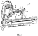
- FIG. 1 is a perspective view of an exemplary power tool, including one example of a power tool wire form hook assembly in accordance with the present disclosure.
- FIG. 2 is a perspective view of the example power tool wire form hook assembly of FIG. 1 .
- FIG. 3 is an exploded view of the example power tool wire form hook assembly of FIG. 1 .
- FIG. 4 is a cross-section view of the example power tool wire form hook assembly of FIG. 1 , with the hook end in a storage position.
- FIG. 5 is a cross-section view of the example power tool wire form hook assembly of FIG. 1 , with the hook end in transition between the storage position of FIG. 4 and the in-use position of FIG. 6 .
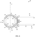
- FIG. 6 is a cross-section view of the example power tool wire form hook assembly of FIG. 1 , with the hook end in an in-use position.
- FIGS. 1-6 illustrate one example of a power tool wire hook assembly 20 for hanging the power tool 24 in accordance with the present disclosure.
- a cordless electric stapler or nail gun such as the framing nailer power tool 24 of FIG. 1
- the power tool 24 can include a housing 26 .
- the housing 26 of the power tool 24 can include two clamshell housing halves 28 , a magazine housing 58 , and a battery coupling housing 38 .
- the housing 26 of the power tool 24 can additionally include a housing groove 30 that can extend circumferentially around a portion of the power tool 24 .
- the housing groove 30 can be provided by a housing component 32 that is separate from the clamshell halves 28 of the housing 26 .
- the housing component 32 can be mounted at a base 34 of a handle 36 of the power tool 24 .
- the annular housing 32 can be mounted between the handle 36 and a battery receptacle or coupling housing 38 .
- the separate housing component 32 can be a single-piece housing component 32 and can have an overall annular shape.
- a single-piece housing 32 can include both opposing edge walls 40 of the housing groove 30 .
- the single-piece housing component 32 can include both of the opposing side walls 40 throughout the entire circumference of the housing groove 30 .
- each of the clamshell halves 28 can provide a single-piece housing component that can include both opposing edge walls 40 of the housing groove 30 .
- each single-piece clamshell half 28 can provide a single-piece housing component 28 that can include both opposing edge walls 40 of each radial half of the housing groove 30 .
- the edge walls 40 of the housing groove 30 that oppose each other can be provided by a single-piece component.
- the clamshell housing halves 28 example no additional components are required to fully form the housing groove 30 beyond the clamshell housing halves 28 themselves.
- the power tool wire form hook assembly can be formed as an independent assembled unit. Each of these can minimize the number of parts required for the assembly 20 , can simplify manufacturing and assembly, or both.
- a wire 42 can include a central bend 44 that can form a distal hook end 46 of a wire body 48 .
- the wire 42 can also include two proximal free ends 50 that together form a coupling end 52 of the wire body 48 .
- the coupling end 52 of the wire can be received in, and slidable around or along, the housing groove 30 .
- the groove 30 can have at least one detent 54
- the coupling end 52 of the wire 42 or wire body 48 can have at least one cooperating detent 56 .
- the example detents 54 of the groove 30 can be provided as flats along the circumference of the groove 30 and the cooperating detents 56 of the wire 42 can be provided as cooperating flats along the coupling end 52 of the wire 42 .
- the detents 54 and cooperating detents 56 can combine to total at least three.
- the groove 30 can be provided with four detents 54 and the coupling end 52 of the wire 42 can be provided with four corresponding detents 56 ; combining to total eight.
- the detents 54 of the groove 30 and the cooperating detents 56 of the wire 42 can be selectively engaged with each other to position and retain the hook end 46 in a storage position in which the hook end 46 is adjacent the power tool housing 26 .
- the hook end 46 can be positioned in alignment with the primary central plane (indicated by “P” in the figures) of the power tool 24 , and can extend alongside the magazine housing 58 in the storage position.
- the hook end 46 can be located in the storage position within a central opening or window 60 of the housing 26 of the power tool 24 .
- This window 60 can be defined by clamshell housing halves 28 including the handle 36 , the battery mount housing 38 , and the magazine housing 58 .
- the detents 54 of the groove 30 and the cooperating detents 56 of the wire 42 can be selectively engaged with each other to position and retain the hook end 46 in an in-use position in which the hook end 46 extends away from the power tool housing 26 ready for use in hanging the tool.
- the wire body 48 can be rotated 90 degrees from the storage position ( FIGS. 1 and 4 ), into an in-use position ( FIG. 6 ) so that the hook end 46 is located on the right side of the tool 24 , and is spaced or extends away from the housing 26 of the power tool 24 .
- the wire body 48 can be rotated an additional 90 degrees (180 degrees total) into another in-use position in which the hook end 46 is located behind the tool and is spaced or extends away from the rear of the tool 24 along the tool plane P.
- the wire body 48 can be rotated again an additional 90 degrees (270 degrees total or 90 degrees in the opposite direction from the storage position) into another in-use position in which the hook end 46 is located on the left side of the tool 24 , and is spaced or extends away from the housing 26 of the power tool 24 .
- the detents 54 and cooperating detents 56 are selectively engaged with each other to help retain the wire body 48 in the selected position.
- the two free ends 50 of the coupling end 52 of the wire 42 can be arranged to engage opposite radial sides of the housing groove 30 .
- the wire 42 can be made of spring steel and the two free ends 50 of the coupling end of the wire 42 can be biased toward each other to facilitate cooperation of the detents 54 , 56 .
- Rotating the wire body 48 between any of the positions in which the detents 54 and cooperating detents 56 are selectively engaged with each other can cause the coupling end 52 to slide along the housing groove 30 ( FIG. 5 ).
- Such rotation of the wire body 48 can also disengage the detents 54 and the cooperating detents 56 from each other and can increase the distance between the two free ends 50 of the wire 42 at the coupling end 52 .
- a wire limiter 62 can be provided to engage and prevent the two free ends 50 of the wire 42 at the coupling end 52 from moving away from each other sufficiently to escape the housing groove 30 .
- the wire limiter 62 can be formed of two components 64 , such as the exemplified upper and lower components, that can be coupled together via a threaded fastener 70 around the two free ends 50 of the wire 42 .
- the two free ends 50 can extend through the wire limiter 62 .
- a first of the two free ends 50 of the wire 42 can extend through a first aperture 66 of the wire limiter 62 and a second of the two free ends 50 can extend through a second aperture 68 of the wire limiter 62 .
- the first aperture 66 can have a circular shape and the second aperture 68 can have an elongated or slotted shape.
- the wire limiter 62 can permit sufficient increase in the distance between the free ends 50 of the wire 42 at the coupling end 52 to permit disengagement of the detents from each other, but prevent this distance from increasing to an extent that the free ends 50 of the wire 42 at the coupling end 52 could escape the groove 30 .
- the housing 26 of the power tool 24 can include a number of housing components or portions, including the clamshell halves 28 , the battery coupling housing 38 , and the magazine housing 58 .
- the annular housing 32 can be a separate component or part from all of these other housing components.
- the annular housing 32 can be a single-piece component that can fully define the entirety of the housing groove 30 .
- the annular housing 32 , the wire 42 forming the hook end 46 and the coupling end 52 of the wire body 48 , and the wire limiter 62 can all be couplable together to form the wire form hook assembly 20 as an independent assembled unit that is separate from the other housing components.
- This independent assembled unit or assembly 20 can be coupled to the one or more of the other housing components.
- the wire form hook assembly 20 can be coupled between the clamshell halves 28 and the battery coupling housing 38 .
Landscapes
- Engineering & Computer Science (AREA)
- Mechanical Engineering (AREA)
- General Engineering & Computer Science (AREA)
- Workshop Equipment, Work Benches, Supports, Or Storage Means (AREA)
Abstract
Description
Claims (24)
Priority Applications (2)
| Application Number | Priority Date | Filing Date | Title |
|---|---|---|---|
| US15/973,004 US10576616B2 (en) | 2018-05-07 | 2018-05-07 | Power tool wire form hook assembly |
| EP19172371.7A EP3566819B1 (en) | 2018-05-07 | 2019-05-02 | Power tool wire form hook assembly |
Applications Claiming Priority (1)
| Application Number | Priority Date | Filing Date | Title |
|---|---|---|---|
| US15/973,004 US10576616B2 (en) | 2018-05-07 | 2018-05-07 | Power tool wire form hook assembly |
Publications (2)
| Publication Number | Publication Date |
|---|---|
| US20190337142A1 US20190337142A1 (en) | 2019-11-07 |
| US10576616B2 true US10576616B2 (en) | 2020-03-03 |
Family
ID=66379839
Family Applications (1)
| Application Number | Title | Priority Date | Filing Date |
|---|---|---|---|
| US15/973,004 Active US10576616B2 (en) | 2018-05-07 | 2018-05-07 | Power tool wire form hook assembly |
Country Status (2)
| Country | Link |
|---|---|
| US (1) | US10576616B2 (en) |
| EP (1) | EP3566819B1 (en) |
Cited By (8)
| Publication number | Priority date | Publication date | Assignee | Title |
|---|---|---|---|---|
| US20200316766A1 (en) * | 2019-04-05 | 2020-10-08 | Makita Corporation | Power tool |
| US11912477B2 (en) | 2022-06-08 | 2024-02-27 | Yeti Coolers, Llc | Container with handle and latching system |
| USD1024557S1 (en) | 2022-06-08 | 2024-04-30 | Yeti Coolers, Llc | Container |
| USD1036116S1 (en) | 2022-06-08 | 2024-07-23 | Yeti Coolers, Llc | Container |
| USD1036119S1 (en) | 2022-11-30 | 2024-07-23 | Yeti Coolers, Llc | Container |
| US12179325B2 (en) | 2022-02-18 | 2024-12-31 | Milwaukee Electric Tool Corporation | Powered fastener driver |
| USD1063376S1 (en) | 2022-06-08 | 2025-02-25 | Yeti Coolers, Llc | Container |
| US12515303B2 (en) | 2023-05-05 | 2026-01-06 | Milwaukee Electric Tool Corporation | Powered fastener driver |
Families Citing this family (3)
| Publication number | Priority date | Publication date | Assignee | Title |
|---|---|---|---|---|
| US10759034B2 (en) * | 2018-02-15 | 2020-09-01 | James Hardie Technology Limited | Systems and methods for fastening a component to a building substrate |
| JP7123592B2 (en) * | 2018-03-23 | 2022-08-23 | 株式会社マキタ | Power tools and power tool couplings |
| DE102021209180A1 (en) | 2021-08-20 | 2023-02-23 | Robert Bosch Gesellschaft mit beschränkter Haftung | Hand-held processing device with a suspension device |
Citations (37)
| Publication number | Priority date | Publication date | Assignee | Title |
|---|---|---|---|---|
| US4784308A (en) | 1986-04-03 | 1988-11-15 | Duo-Fast Corporation | Fastener driving tool |
| US4936499A (en) * | 1989-08-21 | 1990-06-26 | Gulley James L | Tool carrier |
| US5337635A (en) | 1993-02-17 | 1994-08-16 | Habermehl G Lyle | Screwdriving apparatus for use in driving screws joined together in a strip |
| US5699704A (en) | 1993-02-17 | 1997-12-23 | Habermehl; G. Lyle | Exit locating collated screw strips and screwdrivers therefore |
| US6422447B1 (en) | 1998-09-18 | 2002-07-23 | Stanley Fastening Systems, L.P. | Feed system for nailer |
| US6488195B2 (en) | 1998-09-18 | 2002-12-03 | Stanley Fastening Systems, L.P. | Multi-stroke fastening device |
| US6499643B1 (en) | 1998-09-18 | 2002-12-31 | Stanley Fastenening Systems, L.P. | Drive channel for nailer |
| US20030146262A1 (en) | 2002-02-07 | 2003-08-07 | Senco Products, Inc. | Fastener positioning apparatus for a fastener driving tool |
| US6612476B2 (en) | 2002-01-14 | 2003-09-02 | Illinois Tool Works Inc. | Fastener driving tool with modular construction |
| US6672498B2 (en) | 1999-09-17 | 2004-01-06 | Stanley Fastening Sytems Lp | Feed system for nailer |
| US6708821B2 (en) | 2002-08-21 | 2004-03-23 | Illinois Tool Works Inc. | Fastener collation strip and debris exhaust mechanism |
| US6763991B2 (en) | 2001-02-15 | 2004-07-20 | Max Co., Ltd. | Feeding mechanism for connected nails in nailing machine |
| US6808101B2 (en) | 2002-05-24 | 2004-10-26 | Illinois Tool Works Inc. | Framing tool with automatic fastener-size adjustment |
| US20060070761A1 (en) | 2004-10-05 | 2006-04-06 | Mariam Vahabi-Nejad | Multi-position utility hook assembly for tool |
| US20070080278A1 (en) | 2005-10-06 | 2007-04-12 | De Poan Pneumatic Corp. | Hanger for nail driver |
| US7318487B2 (en) | 2005-11-07 | 2008-01-15 | Besco Pneumatic Corp. | Pneumatic tool with an adjustable clip |
| US20090025515A1 (en) | 2007-07-26 | 2009-01-29 | Makita Corporation | Hook structure of power tool |
| US20090134191A1 (en) * | 2007-11-28 | 2009-05-28 | Michael Phillips | Power tool with hook |
| US7565989B2 (en) | 2004-10-19 | 2009-07-28 | Basso Industry Corp. | Hook device for a nailer |
| US20090277939A1 (en) | 2008-05-08 | 2009-11-12 | Panrex Industrial Co., Ltd. | Nail gun hanging device |
| DE202009001797U1 (en) | 2009-02-12 | 2010-07-08 | Metabowerke Gmbh | Tool holder for electric hand tool devices |
| US7922054B2 (en) | 2008-09-23 | 2011-04-12 | Robert Bosch Gmbh | Nail gun with integrated safety device |
| US7942299B2 (en) | 2006-05-31 | 2011-05-17 | Black & Decker Inc. | Hand tool with belt or rafter hook |
| US8167056B2 (en) * | 2008-08-11 | 2012-05-01 | Makita Corporation | Rechargeable electric tool |
| US20140097217A1 (en) * | 2012-09-06 | 2014-04-10 | Sean Michael Walsh | Tool Holding Device |
| US20140097326A1 (en) | 2012-10-04 | 2014-04-10 | Black & Decker Inc. | Rafter Hook for Fastening Tool |
| US8752744B2 (en) | 2008-05-09 | 2014-06-17 | Makita Corporation | Portable tools |
| US20140298664A1 (en) * | 2008-12-30 | 2014-10-09 | Husqvarna Ab | Portable hand-held power tool |
| US8998057B2 (en) | 2011-08-19 | 2015-04-07 | Techtronic Power Tools Technology Limited | Hook assembly for use with a power tool |
| US20160128455A1 (en) | 2014-11-07 | 2016-05-12 | Ty-Flot, Inc. | Tool collet for securing a hand tool to a tool lanyard |
| US9522464B2 (en) * | 2011-05-16 | 2016-12-20 | Illinois Tool Works Inc. | Multi-position utility hook assembly for a tool |
| US9707693B2 (en) * | 2015-03-06 | 2017-07-18 | Chao-Ying LEE | Self-contained docking arrangement for head saw machine |
| US20170225309A1 (en) * | 2016-02-10 | 2017-08-10 | Illinois Tool Works Inc. | Fastener driving tool |
| US20170259422A1 (en) * | 2016-03-10 | 2017-09-14 | Panasonic Intellectual Property Management Co., Ltd. | Tip tool holder and power tool |
| US9889547B2 (en) * | 2016-02-24 | 2018-02-13 | Worktools, Inc. | Selective deployable tool hook |
| US20180132600A1 (en) * | 2016-11-16 | 2018-05-17 | Ty-Flot, Inc. | Tethering assembly and method for grinders and like tools |
| US20180279752A1 (en) * | 2017-03-29 | 2018-10-04 | Tti (Macao Commercial Offshore) Limited | Belt clip for power tool |
-
2018
- 2018-05-07 US US15/973,004 patent/US10576616B2/en active Active
-
2019
- 2019-05-02 EP EP19172371.7A patent/EP3566819B1/en active Active
Patent Citations (42)
| Publication number | Priority date | Publication date | Assignee | Title |
|---|---|---|---|---|
| US4784308A (en) | 1986-04-03 | 1988-11-15 | Duo-Fast Corporation | Fastener driving tool |
| US4936499A (en) * | 1989-08-21 | 1990-06-26 | Gulley James L | Tool carrier |
| US5337635A (en) | 1993-02-17 | 1994-08-16 | Habermehl G Lyle | Screwdriving apparatus for use in driving screws joined together in a strip |
| US5469767A (en) | 1993-02-17 | 1995-11-28 | Habermehl; G. Lyle | Screwdriving apparatus for use in driving screws joined together in a strip |
| US5699704A (en) | 1993-02-17 | 1997-12-23 | Habermehl; G. Lyle | Exit locating collated screw strips and screwdrivers therefore |
| US6422447B1 (en) | 1998-09-18 | 2002-07-23 | Stanley Fastening Systems, L.P. | Feed system for nailer |
| US6488195B2 (en) | 1998-09-18 | 2002-12-03 | Stanley Fastening Systems, L.P. | Multi-stroke fastening device |
| US6499643B1 (en) | 1998-09-18 | 2002-12-31 | Stanley Fastenening Systems, L.P. | Drive channel for nailer |
| US6672498B2 (en) | 1999-09-17 | 2004-01-06 | Stanley Fastening Sytems Lp | Feed system for nailer |
| US6763991B2 (en) | 2001-02-15 | 2004-07-20 | Max Co., Ltd. | Feeding mechanism for connected nails in nailing machine |
| US6612476B2 (en) | 2002-01-14 | 2003-09-02 | Illinois Tool Works Inc. | Fastener driving tool with modular construction |
| US20030146262A1 (en) | 2002-02-07 | 2003-08-07 | Senco Products, Inc. | Fastener positioning apparatus for a fastener driving tool |
| US6808101B2 (en) | 2002-05-24 | 2004-10-26 | Illinois Tool Works Inc. | Framing tool with automatic fastener-size adjustment |
| US6708821B2 (en) | 2002-08-21 | 2004-03-23 | Illinois Tool Works Inc. | Fastener collation strip and debris exhaust mechanism |
| US6892922B2 (en) | 2002-08-21 | 2005-05-17 | Illinois Tool Works Inc. | Fastener collation strip and debris exhaust mechanism |
| US20060070761A1 (en) | 2004-10-05 | 2006-04-06 | Mariam Vahabi-Nejad | Multi-position utility hook assembly for tool |
| US7306052B2 (en) | 2004-10-05 | 2007-12-11 | Illinois Tool Works Inc. | Multi-position utility hook assembly for tool |
| US7565989B2 (en) | 2004-10-19 | 2009-07-28 | Basso Industry Corp. | Hook device for a nailer |
| US20070080278A1 (en) | 2005-10-06 | 2007-04-12 | De Poan Pneumatic Corp. | Hanger for nail driver |
| US7318487B2 (en) | 2005-11-07 | 2008-01-15 | Besco Pneumatic Corp. | Pneumatic tool with an adjustable clip |
| US7942299B2 (en) | 2006-05-31 | 2011-05-17 | Black & Decker Inc. | Hand tool with belt or rafter hook |
| US20090025515A1 (en) | 2007-07-26 | 2009-01-29 | Makita Corporation | Hook structure of power tool |
| US8308034B2 (en) * | 2007-07-26 | 2012-11-13 | Makita Corporation | Hook structure of power tool |
| US20090134191A1 (en) * | 2007-11-28 | 2009-05-28 | Michael Phillips | Power tool with hook |
| US20090277939A1 (en) | 2008-05-08 | 2009-11-12 | Panrex Industrial Co., Ltd. | Nail gun hanging device |
| US8752744B2 (en) | 2008-05-09 | 2014-06-17 | Makita Corporation | Portable tools |
| US8167056B2 (en) * | 2008-08-11 | 2012-05-01 | Makita Corporation | Rechargeable electric tool |
| US7922054B2 (en) | 2008-09-23 | 2011-04-12 | Robert Bosch Gmbh | Nail gun with integrated safety device |
| US20140298664A1 (en) * | 2008-12-30 | 2014-10-09 | Husqvarna Ab | Portable hand-held power tool |
| DE202009001797U1 (en) | 2009-02-12 | 2010-07-08 | Metabowerke Gmbh | Tool holder for electric hand tool devices |
| US9522464B2 (en) * | 2011-05-16 | 2016-12-20 | Illinois Tool Works Inc. | Multi-position utility hook assembly for a tool |
| US8998057B2 (en) | 2011-08-19 | 2015-04-07 | Techtronic Power Tools Technology Limited | Hook assembly for use with a power tool |
| US20140097217A1 (en) * | 2012-09-06 | 2014-04-10 | Sean Michael Walsh | Tool Holding Device |
| US8960635B2 (en) | 2012-10-04 | 2015-02-24 | Black & Decker Inc. | Rafter hook for fastening tool |
| US20140097326A1 (en) | 2012-10-04 | 2014-04-10 | Black & Decker Inc. | Rafter Hook for Fastening Tool |
| US20160128455A1 (en) | 2014-11-07 | 2016-05-12 | Ty-Flot, Inc. | Tool collet for securing a hand tool to a tool lanyard |
| US9707693B2 (en) * | 2015-03-06 | 2017-07-18 | Chao-Ying LEE | Self-contained docking arrangement for head saw machine |
| US20170225309A1 (en) * | 2016-02-10 | 2017-08-10 | Illinois Tool Works Inc. | Fastener driving tool |
| US9889547B2 (en) * | 2016-02-24 | 2018-02-13 | Worktools, Inc. | Selective deployable tool hook |
| US20170259422A1 (en) * | 2016-03-10 | 2017-09-14 | Panasonic Intellectual Property Management Co., Ltd. | Tip tool holder and power tool |
| US20180132600A1 (en) * | 2016-11-16 | 2018-05-17 | Ty-Flot, Inc. | Tethering assembly and method for grinders and like tools |
| US20180279752A1 (en) * | 2017-03-29 | 2018-10-04 | Tti (Macao Commercial Offshore) Limited | Belt clip for power tool |
Non-Patent Citations (1)
| Title |
|---|
| Extended European Search Report dated Oct. 2, 2019 in European Patent Application No. 19172371.7. |
Cited By (10)
| Publication number | Priority date | Publication date | Assignee | Title |
|---|---|---|---|---|
| US20200316766A1 (en) * | 2019-04-05 | 2020-10-08 | Makita Corporation | Power tool |
| US11559879B2 (en) * | 2019-04-05 | 2023-01-24 | Makita Corporation | Power tool |
| US12179325B2 (en) | 2022-02-18 | 2024-12-31 | Milwaukee Electric Tool Corporation | Powered fastener driver |
| US11912477B2 (en) | 2022-06-08 | 2024-02-27 | Yeti Coolers, Llc | Container with handle and latching system |
| USD1024557S1 (en) | 2022-06-08 | 2024-04-30 | Yeti Coolers, Llc | Container |
| USD1036116S1 (en) | 2022-06-08 | 2024-07-23 | Yeti Coolers, Llc | Container |
| USD1063376S1 (en) | 2022-06-08 | 2025-02-25 | Yeti Coolers, Llc | Container |
| USD1036119S1 (en) | 2022-11-30 | 2024-07-23 | Yeti Coolers, Llc | Container |
| USD1083381S1 (en) | 2022-11-30 | 2025-07-15 | Yeti Coolers, Llc | Container |
| US12515303B2 (en) | 2023-05-05 | 2026-01-06 | Milwaukee Electric Tool Corporation | Powered fastener driver |
Also Published As
| Publication number | Publication date |
|---|---|
| EP3566819B1 (en) | 2023-09-27 |
| EP3566819A1 (en) | 2019-11-13 |
| US20190337142A1 (en) | 2019-11-07 |
Similar Documents
| Publication | Publication Date | Title |
|---|---|---|
| US10576616B2 (en) | Power tool wire form hook assembly | |
| US6860758B1 (en) | Snap fitting electrical connector | |
| US10050427B2 (en) | Cable connector and electrical box | |
| US6364716B1 (en) | Adaptor with rotary plug | |
| US7214890B2 (en) | Electrical connector having an outlet end angularly disposed relative an inlet end with outer retainer ring about the outlet end and internal unidirectional conductor retainer in the inlet end | |
| US9879803B2 (en) | Connectable cable organizer | |
| JP3202594U (en) | Fastener head combination structure and slider for increasing torsional strength | |
| US20090120687A1 (en) | Electrical connector with outer retainer ring and internal unidirectional conductor retainer | |
| US20080149388A1 (en) | Electrical duplex connector having an integrally formed connector body with a frustro-conical retaining ring and unidirectional cable retainers | |
| US7222394B2 (en) | Bushing for metal studs and the like | |
| US20090178845A1 (en) | Electrical connector assembly with enhanced grounding | |
| EP2799184A1 (en) | Angle grinder dust shroud | |
| US20190190179A1 (en) | Electrical terminal housing with releasable terminal locks | |
| US9797581B2 (en) | Lamp | |
| US20200136359A1 (en) | Link and wire harness | |
| EP3442084B1 (en) | Terminal locator for crimping tools | |
| US7189107B1 (en) | Power module having retractable cord | |
| JP2015153488A (en) | connector | |
| US20190199072A1 (en) | Knife Accessory for Hot Stick | |
| JP2018037365A (en) | connector | |
| JP5087020B2 (en) | connector | |
| US10777938B2 (en) | Connector | |
| US7017867B2 (en) | Wheel-like wire holder | |
| JP6720236B2 (en) | Connecting terminal | |
| CN100479265C (en) | Connecting device for conductive contact and handle of electric connector |
Legal Events
| Date | Code | Title | Description |
|---|---|---|---|
| FEPP | Fee payment procedure |
Free format text: ENTITY STATUS SET TO UNDISCOUNTED (ORIGINAL EVENT CODE: BIG.); ENTITY STATUS OF PATENT OWNER: LARGE ENTITY |
|
| AS | Assignment |
Owner name: BLACK & DECKER INC., CONNECTICUT Free format text: ASSIGNMENT OF ASSIGNORS INTEREST;ASSIGNORS:HAYS, JAMES D.;WENIG, JOHN C.;REEL/FRAME:046892/0711 Effective date: 20180808 |
|
| STPP | Information on status: patent application and granting procedure in general |
Free format text: NOTICE OF ALLOWANCE MAILED -- APPLICATION RECEIVED IN OFFICE OF PUBLICATIONS |
|
| STPP | Information on status: patent application and granting procedure in general |
Free format text: NOTICE OF ALLOWANCE MAILED -- APPLICATION RECEIVED IN OFFICE OF PUBLICATIONS |
|
| STPP | Information on status: patent application and granting procedure in general |
Free format text: PUBLICATIONS -- ISSUE FEE PAYMENT RECEIVED |
|
| STCF | Information on status: patent grant |
Free format text: PATENTED CASE |
|
| MAFP | Maintenance fee payment |
Free format text: PAYMENT OF MAINTENANCE FEE, 4TH YEAR, LARGE ENTITY (ORIGINAL EVENT CODE: M1551); ENTITY STATUS OF PATENT OWNER: LARGE ENTITY Year of fee payment: 4 |