US10564762B2 - Electronic apparatus and control method thereof - Google Patents
Electronic apparatus and control method thereof Download PDFInfo
- Publication number
- US10564762B2 US10564762B2 US15/259,556 US201615259556A US10564762B2 US 10564762 B2 US10564762 B2 US 10564762B2 US 201615259556 A US201615259556 A US 201615259556A US 10564762 B2 US10564762 B2 US 10564762B2
- Authority
- US
- United States
- Prior art keywords
- touch
- move
- approach
- determination
- determined
- Prior art date
- Legal status (The legal status is an assumption and is not a legal conclusion. Google has not performed a legal analysis and makes no representation as to the accuracy of the status listed.)
- Expired - Fee Related, expires
Links
Images


Classifications
-
- G—PHYSICS
- G06—COMPUTING OR CALCULATING; COUNTING
- G06F—ELECTRIC DIGITAL DATA PROCESSING
- G06F3/00—Input arrangements for transferring data to be processed into a form capable of being handled by the computer; Output arrangements for transferring data from processing unit to output unit, e.g. interface arrangements
- G06F3/01—Input arrangements or combined input and output arrangements for interaction between user and computer
- G06F3/03—Arrangements for converting the position or the displacement of a member into a coded form
- G06F3/041—Digitisers, e.g. for touch screens or touch pads, characterised by the transducing means
- G06F3/0416—Control or interface arrangements specially adapted for digitisers
-
- G—PHYSICS
- G06—COMPUTING OR CALCULATING; COUNTING
- G06F—ELECTRIC DIGITAL DATA PROCESSING
- G06F3/00—Input arrangements for transferring data to be processed into a form capable of being handled by the computer; Output arrangements for transferring data from processing unit to output unit, e.g. interface arrangements
- G06F3/01—Input arrangements or combined input and output arrangements for interaction between user and computer
- G06F3/03—Arrangements for converting the position or the displacement of a member into a coded form
- G06F3/041—Digitisers, e.g. for touch screens or touch pads, characterised by the transducing means
- G06F3/044—Digitisers, e.g. for touch screens or touch pads, characterised by the transducing means by capacitive means
- G06F3/0446—Digitisers, e.g. for touch screens or touch pads, characterised by the transducing means by capacitive means using a grid-like structure of electrodes in at least two directions, e.g. using row and column electrodes
-
- G—PHYSICS
- G06—COMPUTING OR CALCULATING; COUNTING
- G06F—ELECTRIC DIGITAL DATA PROCESSING
- G06F3/00—Input arrangements for transferring data to be processed into a form capable of being handled by the computer; Output arrangements for transferring data from processing unit to output unit, e.g. interface arrangements
- G06F3/01—Input arrangements or combined input and output arrangements for interaction between user and computer
- G06F3/048—Interaction techniques based on graphical user interfaces [GUI]
- G06F3/0487—Interaction techniques based on graphical user interfaces [GUI] using specific features provided by the input device, e.g. functions controlled by the rotation of a mouse with dual sensing arrangements, or of the nature of the input device, e.g. tap gestures based on pressure sensed by a digitiser
- G06F3/0488—Interaction techniques based on graphical user interfaces [GUI] using specific features provided by the input device, e.g. functions controlled by the rotation of a mouse with dual sensing arrangements, or of the nature of the input device, e.g. tap gestures based on pressure sensed by a digitiser using a touch-screen or digitiser, e.g. input of commands through traced gestures
- G06F3/04883—Interaction techniques based on graphical user interfaces [GUI] using specific features provided by the input device, e.g. functions controlled by the rotation of a mouse with dual sensing arrangements, or of the nature of the input device, e.g. tap gestures based on pressure sensed by a digitiser using a touch-screen or digitiser, e.g. input of commands through traced gestures for inputting data by handwriting, e.g. gesture or text
Definitions
- the present invention relates to a technique for determining an operation performed on a touchscreen.
- Many electronic apparatuses such as smartphones and digital cameras, are equipped with touchscreens, and can perform control in accordance with a trajectory of a touch position formed by moving a finger or stylus while the finger or stylus is in contact with the touchscreens. Specifically, an operating amount and an operating direction are determined from a trajectory of a moved touch position, and when a predetermined condition is satisfied, it is determined that a touch operation has been performed and control allocated thereto is executed.
- an operating direction and an operating amount are determined under the same condition, regardless of the form of a touch operation (an operating direction (operating angle), inclination, and operating amount of a finger or stylus); thus, there are cases in which some forms of touch operations are difficult to perform. For this reason, there is a possibility that a touch operation is not determined accurately and a function intended by a user is not executed.
- Japanese Patent Laid-Open No. 2011-134260 describes changing of a touch operation determination condition based on the history of touchscreen operations.
- Japanese Patent Laid-Open No. 2013-080999 describes changing of a determination condition for control to be executed based on the way of gripping an apparatus, an operating direction on a touchscreen, and a display image.
- the present invention has been made in consideration of the aforementioned problems, and realizes, at low cost, an apparatus that can accurately determine a touch operation intended by a user regardless of the form of the touch operation.
- the present invention provides an electronic apparatus, comprising: a touch detection unit configured to detect a touch operation performed on an operation surface by an operation body; a determination unit configured to, on an occurrence of a move operation in which the operation body moves while in contact with the operation surface, determine an operating direction of the move operation under a determination condition that varies according to an approach direction of the operation body toward the operation surface; and a control unit configured to perform control to execute a function corresponding to the operating direction determined by the determination unit.
- the present invention provides an electronic apparatus, comprising: a touch detection unit configured to detect a touch operation performed on an operation surface by an operation body; a determination unit configured to, on an occurrence of a move operation in which the operation body moves while in contact with the operation surface, determine an operating direction of the move operation under a determination condition that varies according to an inclined state of the operation body with respect to the operation surface; and a control unit configured to perform control to execute a function corresponding to the operating direction determined by the determination unit.
- the present invention provides an electronic apparatus, comprising: a touch detection unit configured to detect a touch operation performed on an operation surface by an operation body, the touch detection unit being a capacitance-type touch sensor; a determination unit configured to, on an occurrence of a move operation in which the operation body moves while in contact with the operation surface, determine an operating direction of the move operation under a determination condition that varies according to a distribution of capacitances generated due to proximity of the operation body that has performed the move operation to the operation surface; and a control unit configured to perform control to execute a function corresponding to the operating direction determined by the determination unit.
- the present invention provides an electronic apparatus, comprising: a touch detection unit configured to detect a touch operation performed on an operation surface by an operation body; a determination unit configured to, on an occurrence of a move operation in which the operation body moves while in contact with the operation surface, determine an operating direction of the move operation under a determination condition that varies according to a touch input angle of the operation body on the operation surface with respect to a predetermined direction along the operation surface; and a control unit configured to perform control to execute a function corresponding to the operating direction determined by the determination unit.
- the present invention provides a control method of an electronic apparatus having a touch detection unit configured to detect a touch operation performed on an operation surface by an operation body, the method comprising: on an occurrence of a move operation in which the operation body moves while in contact with the operation surface, determining an operating direction of the move operation under a determination condition that varies according to an approach direction of the operation body toward the operation surface; and performing control to execute a function corresponding to the determined operating direction.
- the present invention provides a control method of an electronic apparatus having a touch detection unit configured to detect a touch operation performed on an operation surface by an operation body, the method comprising: on an occurrence of a move operation in which the operation body moves while in contact with the operation surface, determining an operating direction of the move operation under a determination condition that varies according to an inclined state of the operation body with respect to the operation surface; and performing control to execute a function corresponding to the determined operating direction.
- the present invention provides a control method of an electronic apparatus having a touch detection unit configured to detect a touch operation performed on an operation surface by an operation body, the touch detection unit being a capacitance-type touch sensor, the method comprising: on an occurrence of a move operation in which the operation body moves while in contact with the operation surface, determining an operating direction of the move operation under a determination condition that varies according to a distribution of capacitances generated due to proximity of the operation body that has performed the move operation to the operation surface; and performing control to execute a function corresponding to the determined operating direction.
- the present invention provides a control method of an electronic apparatus having a touch detection unit that detects a touch operation performed on an operation surface by an operation body, the method comprising: on an occurrence of a move operation in which the operation body moves while in contact with the operation surface, determining an operating direction of the move operation under a determination condition that varies according to a touch input angle of the operation body on the operation surface with respect to a predetermined direction along the operation surface; and performing control to execute a function corresponding to the determined operating direction.
- the present invention provides a non-transitory computer-readable storage medium storing a program for causing a computer to function as a determination unit and a control unit of an electronic apparatus having a touch detection unit configured to detect a touch operation performed on an operation surface by an operation body, wherein the determination unit, on an occurrence of a move operation in which the operation body moves while in contact with the operation surface, determines an operating direction of the move operation under a determination condition that varies according to an approach direction of the operation body toward the operation surface, and the control unit performs control to execute a function corresponding to the operating direction determined by the determination unit.
- the present invention provides a non-transitory computer-readable storage medium storing a program for causing a computer to function as a determination unit and a control unit of an electronic apparatus having a touch detection unit configured to detect a touch operation performed on an operation surface by an operation body, wherein the determination unit, on an occurrence of a move operation in which the operation body moves while in contact with the operation surface, determines an operating direction of the move operation under a determination condition that varies according to an inclined state of the operation body with respect to the operation surface, and the control unit performs control to execute a function corresponding to the operating direction determined by the determination unit.
- the present invention provides a non-transitory computer-readable storage medium storing a program for causing a computer to function as a determination unit and a control unit of an electronic apparatus having a touch detection unit configured to detect a touch operation performed on an operation surface by an operation body, using a capacitance-type touch sensor, wherein the determination unit, on an occurrence of a move operation in which the operation body moves while in contact with the operation surface, determines an operating direction of the move operation under a determination condition that varies according to a distribution of capacitances generated due to proximity of the operation body that has performed the move operation to the operation surface, and the control unit performs control to execute a function corresponding to the operating direction determined by the determination unit.
- the present invention provides a non-transitory computer-readable storage medium storing a program for causing a computer to function as a determination unit and a control unit of an electronic apparatus having a touch detection unit configured to detect a touch operation performed on an operation surface by an operation body, wherein the determination unit, on an occurrence of a move operation in which the operation body moves while in contact with the operation surface, determines an operating direction of the move operation under a determination condition that varies according to a touch input angle of the operation body on the operation surface with respect to a predetermined direction along the operation surface, and the control unit performs control to execute a function corresponding to the operating direction determined by the determination unit.
- the present invention can realize, at low cost, an apparatus that can accurately determine a touch operation intended by a user regardless of the form of the touch operation.
- FIG. 1 is a block diagram showing a configuration of a touchscreen-equipped electronic apparatus according to the embodiments.
- FIGS. 2A to 2F are diagrams for describing a method of determining an inclined state of a touch operation member according to a first embodiment.
- FIGS. 3A to 3J are diagrams for describing a method of estimating an inclination angle of the touch operation member and a method of determining a touch approach direction of the same according to the first embodiment.
- FIG. 4 exemplarily shows a selection table according to the first embodiment, indicating a condition-change target direction for each variety of the touch approach direction.
- FIGS. 5A to 5C are flowcharts of processing for controlling a touch operation determination condition in accordance with the touch approach direction in the first embodiment.
- FIGS. 6A to 6I are diagrams for describing specific examples of the processing for controlling a touch operation determination condition shown in FIGS. 5A to 5C .
- FIGS. 7A and 7B are diagrams for describing a method of determining the size of a touch region according to a second embodiment.
- FIG. 8 exemplarily shows a selection table according to the second embodiment, indicating a condition-change target direction for each variety of a touch approach direction in consideration of the size of a touch region.
- FIGS. 9A to 9C are flowcharts of processing for controlling a touch operation determination condition in accordance with the touch approach direction and the size of the touch region in the second embodiment.
- FIGS. 10A to 10D are diagrams for describing processing for determining a touch input angle with respect to a touchscreen in-plane axis according to a third embodiment.
- FIGS. 11A to 11H are diagrams for describing specific examples of the processing for determining the touch input angle shown in FIGS. 10A to 10D .
- FIG. 12 exemplarily shows a selection table according to the third embodiment, indicating a condition-change target direction for each range of the touch input angle with respect to the touchscreen in-plane axis.
- FIG. 13 is a flowchart of processing for controlling a touch operation determination condition in accordance with the touch input angle with respect to the touchscreen in-plane axis in the third embodiment.
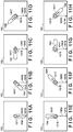
- FIGS. 14A to 14I are diagrams for describing specific examples of the processing for controlling a touch operation determination condition in the third embodiment.
- FIG. 15 exemplarily shows a selection table according to a fourth embodiment, indicating a condition-change target direction for each range of a touch input angle.
- FIG. 16 is a flowchart of processing for controlling a touch operation determination condition in accordance with the touch input angle and the size of a touch region in the fourth embodiment.
- an electronic apparatus of the present invention is applied to, for example, a smartphone or a tablet including a touchscreen-equipped display unit.
- a main control unit 112 , an internal storage medium 113 , a memory 114 , an input unit 115 , a condition setting unit 116 , a display control unit 117 , a storage medium I/F 119 , and a communication I/F 121 are connected to an internal bus 101 , and can exchange data with one another via the internal bus 101 .
- a touchscreen 102 includes capacitance-type touch sensors 103 , which are composed of touch sensors (sensor electrodes) 103 a, 103 b arranged two-dimensionally, and generates capacitances C between itself and a touch operation member 104 (an operation body), which is a finger, a stylus, or a similar conductive element.
- touch sensors 103 are not limited to having the shape of a rhombus.
- horizontal axis direction sensors 103 a generate capacitances during a touch operation in the X-axis direction (horizontal direction) in the figure
- vertical axis direction sensors 103 b generate capacitances during a touch operation in the Y-axis direction (vertical direction) in the figure.
- generated capacitances C represent capacitances between the horizontal axis direction sensors 103 a or the vertical axis direction sensors 103 b and GND; alternatively, capacitances between the horizontal axis direction sensors 103 a and the vertical axis direction sensors 103 b may be detected.
- a touch sensor driving circuit 106 includes a touch detection unit 107 , a coordinate position calculation unit 109 , an inclined state determination unit 111 , a touch input angle determination unit 124 , and a touch state determination unit 123 .
- the touch detection unit 107 determines whether a touch operation has been performed by comparing generated capacitance of each sensor 103 a, 103 b (or inter-sensor capacitance) C with a touch detection threshold 108 ; for example, it determines that a touch operation has been performed when generated capacitance 105 is larger than the touch detection threshold 108 .
- the coordinate position calculation unit 109 calculates the coordinates of a touch position by calculating, for example, the center of mass 110 from generated capacitance C detected by each sensor 103 a, 103 b. Note that when the touch sensors 103 are arranged in three or more dimensions, the center of mass 110 is calculated for each of the depth-, width-, and height-axis directions.
- the inclined state determination unit 111 determines an inclined state of the touch operation member 104 that has performed a touch operation with respect to a touchscreen surface (inclination determination), using capacitances C generated by touch sensors when the touch detection unit 107 determines that the touch operation has been performed.
- the touch input angle determination unit 124 determines a touch input angle of the touch operation member 104 with respect to a predetermined axis in a direction along the touchscreen surface (a touchscreen in-plane axis) (touch input angle determination), using inter-sensor capacitances C generated by touch sensors when the touch detection unit 107 determines that a touch operation has been performed.
- the touch state determination unit 123 determines a direction of a touch operation and a size of a touch region from the distribution of capacitances C generated by touch sensors when the touch detection unit 107 determines that the touch operation has been performed, and from the results of determination by the inclined state determination unit 111 and the touch input angle determination unit 124 .
- the main control unit 112 includes a CPU/MPU that performs integrated control over the entire electronic apparatus 100 .
- the internal storage medium 113 is a hard disk or a memory card that stores, for example, data, such as image data, and later-described programs executed by the main control unit 112 .
- the memory 114 is, for example, a RAM, and the main control unit 112 controls various components of the electronic apparatus 100 by deploying programs stored in the internal storage medium 113 to the memory 114 , which serves as a working memory, and executing the deployed programs.
- programs related to the actions of the main control unit 112 are not limited to being stored in the internal storage medium 113 ; they may be prestored in, for example, an EEPROM or a similar nonvolatile memory.
- the input unit 115 accepts a touch operation performed on the touchscreen 102 by the touch operation member 104 , generates a detection signal corresponding to capacitances C generated during the touch operation, and outputs the detection signal to the main control unit 112 and the later-described condition setting unit 116 .
- the condition setting unit 116 changes, for example, a moving distance threshold as a later-described touch operation determination condition in accordance with, for example, an approach direction, an inclination angle, and a touch input angle of the touch operation member 104 .
- the main control unit 112 controls various components of the electronic apparatus 100 based on the detection signal, which is output from the input unit 115 in accordance with a touch operation performed on the touchscreen 102 , and the touch operation determination condition set by the condition setting unit 116 . This enables the electronic apparatus 100 to execute processing corresponding to a user operation.
- the display control unit 117 generates a display signal for displaying images based on a display control signal from the main control unit 112 , and outputs the display signal to a display unit 118 .
- the display control unit 117 thus causes the display unit 118 to display a graphical user interface (GUI) screen in accordance with, for example, the display control signal from the main control unit 112 .
- GUI graphical user interface
- the touchscreen 102 and the display unit 118 may be formed integrally.
- the touchscreen 102 is configured in such a manner that its light transmittance does not obstruct a display performance by the display unit 118 , and is mounted over a display surface of the display unit 118 .
- touch input coordinates on the touchscreen 102 are associated with display coordinates on the display unit 118 .
- a GUI can be configured that enables a user to directly operate a screen displayed on the display unit 118 .
- An external storage medium 120 such as a memory card, is attachable to and detachable from the storage medium I/F 119 , and the storage medium I/F 119 reads out data from and writes data to the external storage medium 120 based on a control signal from the main control unit 112 .
- the external storage medium 120 is not limited to the memory card and the like; it may be an optical disc, such as a CD, DVD, and Blu-ray Disc.
- the communication I/F 121 Based on a control signal from the main control unit 112 , the communication I/F 121 connects to a wireless or wired network 122 , such as a LAN and the Internet, to communicate with a server and an external apparatus.
- a wireless or wired network 122 such as a LAN and the Internet
- main control unit 112 can detect the following operations/states on an operation surface of the touchscreen 102 .
- a touch-on When a touch-down is detected, a touch-on is also detected simultaneously. Normally, after a touch-down, a touch-on is continuously detected unless a touch-up is detected. A touch-move is detected also while a touch-on is being detected. While a touch-on is being detected, a touch-move is not detected if a touch position does not move. A touch-off is detected upon detection of a touch-up, that is to say, releasing of contact between the touchscreen 102 and all fingers or a stylus. In order to prevent a minute movement caused by, for example, shaking of a finger from being erroneously detected as a touch-move, a movement equal to or larger than a threshold is determined as a touch-move.
- this moving distance threshold for determining that a touch-move has been performed is changed for each touch-move direction, in accordance with an approach direction of a touching finger or stylus (a moving direction of, for example, the base of the finger or the end of the stylus opposite to a touch position).
- the main control unit 112 is notified of the aforementioned operations/states on the touchscreen 102 , as well as the position coordinates on the touchscreen 102 that are touched by a finger or stylus, via the internal bus 101 .
- the main control unit 112 determines what kind of operation has been performed on the touchscreen 102 based on information that it has been notified of.
- a touch-move a moving direction of a finger or stylus moving on the touchscreen 102 can be determined separately for a vertical component and a horizontal component on the touchscreen 102 based on changes in the position coordinates.
- a touch-down, a certain touch-move, and a touch-up are successively performed in this order on the touchscreen 102 , it is determined that a stroke has been performed.
- a flick is an operation whereby a finger or stylus is quickly moved by a certain distance while in contact with the touchscreen 102 and then released from the touchscreen 102 ; in other words, a flick is an operation of quickly flicking on the touchscreen 102 with a finger. It is determined that a flick has been performed when a touch-up is detected immediately after detection of a touch-move of a predetermined distance or longer at a predetermined speed or higher.
- this predetermined distance set for a flick (a distance threshold for determining that a flick has been performed) is changed for each touch-move direction, in accordance with an approach direction of a touching finger or stylus. Furthermore, it is determined that a drag has been performed when a touch-move of a predetermined distance or longer at a speed lower than a predetermined speed is detected.
- the present embodiment involves processing for determining an approach direction (touch approach direction) of the touch operation member 104 that has performed a touch operation in accordance with an inclined state of the touch operation member 104 with respect to the touchscreen surface, and changing a touch operation determination condition based on the touch approach direction.
- a touch sensor 201 is a sensor that generates the largest capacitance 205 (a largest capacitance sensor).
- Touch sensors 202 , 203 are sensors that are adjacent to the periphery of the largest capacitance sensor 201 (adjacent sensors).
- a difference value 204 is obtained by subtracting the capacitance 206 generated by the adjacent sensor 202 from the capacitance 205 generated by the largest capacitance sensor 201 .
- a difference value 207 is obtained by subtracting the capacitance 208 generated by the adjacent sensor 203 from the capacitance 205 generated by the largest capacitance sensor 201 . Note that the difference values 204 and 207 are both referred to as difference values A.
- a first threshold 209 is a determination criterion that is set for the difference values 204 , 207 to determine whether there is a possibility of that the touch operation member 104 is inclined.
- a touch sensor 210 is a different sensor (distant sensor) that is not adjacent to the largest capacitance sensor 201 but is adjacent to the adjacent sensor 202 or 203 .
- a difference value 211 is obtained by subtracting the capacitance 212 generated by the distant sensor 210 from the capacitance 206 generated by the adjacent sensor 202 . Note that the difference value 211 is referred to as a difference value B.
- a second threshold 213 is a determination criterion that is set for the difference value 211 to determine whether there is a possibility that the touch operation member 104 is inclined.
- a third threshold 214 is a determination criterion that is set for the capacitance 208 generated by the adjacent sensor 203 to determine whether there is a possibility that the touch operation member 104 is inclined.
- a fourth threshold 215 is a determination criterion that is set for the capacitance 208 generated by the adjacent sensor 203 to determine whether there is a possibility that the touch operation member 104 is inclined.
- FIGS. 2A, 2C, and 2E show examples of the distribution of capacitances C that are generated due to the proximity of the operation body when the touch operation member 104 is determined to be inclined.
- FIGS. 2B, 2D, and 2F show examples of the distribution of capacitances C that are generated due to the proximity of the operation body when the touch operation member 104 is not determined to be inclined.
- the difference values of generated capacitances C from a distal portion of the touch operation member 104 (corresponding to the largest capacitance sensor 201 ) to a proximal portion thereof (corresponding to the adjacent sensor 202 or 203 and the distant sensor 210 ) are small.
- the difference values of generated capacitances C at the periphery of the touch operation member 104 (corresponding to the adjacent sensor 202 or 203 ) and the proximal portion thereof (corresponding to the distant sensor 210 ) are large.
- Touch sensors 301 , 302 are inclination-side sensors that are located along the direction of inclination of the touch operation member 104 relative to the largest capacitance sensor 201 .
- a difference value 303 is obtained by subtracting the capacitance 305 generated by the inclination-side sensor 301 from the capacitance 205 generated by the largest capacitance sensor 201 .
- a difference value 304 is obtained by subtracting the capacitance 306 generated by the inclination-side sensor 302 from the capacitance 205 generated by the largest capacitance sensor 201 .
- An inclination angle 307 is an angle formed by the touch operation member 104 and the touchscreen 102 . Note that the angle may be replaced with any index that indicates the extent of inclination.
- the inclination angle 307 is also referred to as an inclination angle ⁇ .
- a fifth threshold 308 is a determination criterion that is set for the inclination angle 307 to determine whether there is a possibility that the touch operation member 104 is inclined to the extent that the determination of the touch approach direction is affected.
- FIG. 3A exemplarily shows the distribution of capacitances C when the inclination angle ⁇ of the touch operation member 104 is large (the inclination angle 307 is larger than the fifth threshold 308 ).
- FIG. 3B exemplarily shows the distribution of capacitances C when the inclination angle ⁇ of the touch operation member is small (the inclination angle 307 is smaller than the fifth threshold 308 ).
- FIGS. 3C to 3J show specific examples of a touch approach direction that is determined when the inclination angle ⁇ of the touch operation member 104 is large (see FIG. 3A ). It will be assumed that the touch sensors 103 are arranged two-dimensionally along the display surface of the display unit 118 . For the sake of explanation, it will also be assumed that the touch approach direction is from one of the following eight directions: up, down, left, right, and four diagonal directions.
- the touch approach direction is determined as follows, separately for an X-axis (horizontal) direction component and a Y-axis (vertical) direction component: when a difference between output values of adjacent sensors that adjacently sandwich the largest capacitance sensor is equal to or larger than a threshold on the occurrence of a touch operation, it is determined that the approach has been made by traversing one of the adjacent sensors with a larger output value. On the other hand, when the difference between the output values of the adjacent sensors that adjacently sandwich the largest capacitance sensor is smaller than the threshold on the occurrence of the touch operation, it is determined that no approach has been made along the corresponding direction component. As described above, the approach direction is determined based on a combination of determination of the approach direction for the X-axis (horizontal) direction component and determination of the approach direction for the Y-axis (vertical) direction component.
- the X-axis (horizontal) direction component shows that the difference between the output values of the adjacent sensors that adjacently sandwich the largest capacitance sensor is smaller than the threshold; therefore, it is determined that the approach has not been made in the X-axis direction.
- the Y-axis (vertical) direction component shows that the difference between the output values of the adjacent sensors that adjacently sandwich the largest capacitance sensor is equal to or larger than the threshold, and the adjacent sensor on the lower side has a larger output value; therefore, with respect to the Y-axis direction component, it is determined that the approach has been made from down. Based on a combination of the X-axis component (none) and the Y-axis component (from down), it is determined that the touch approach direction is from down.
- the X-axis (horizontal) direction component shows that the difference between the output values of the adjacent sensors that adjacently sandwich the largest capacitance sensor is equal to or larger than the threshold, and the adjacent sensor on the left has a larger output value; therefore, with respect to the X-axis direction component, it is determined that the approach has been made from left.
- the Y-axis (vertical) direction component shows that the difference between the output values of the adjacent sensors that adjacently sandwich the largest capacitance sensor is equal to or larger than the threshold, and the adjacent sensor on the lower side has a larger output value; therefore, with respect to the Y-axis direction component, it is determined that the approach has been made from down.
- the touch approach direction is from lower left.
- the touch approach direction is determined using a similar determination method.
- FIG. 3E it is determined that the touch approach direction is from left.
- FIG. 3F it is determined that the touch approach direction is from upper left.
- FIG. 3G it is determined that the touch approach direction is from up.
- FIG. 3H it is determined that the touch approach direction is from upper right.
- FIG. 3I it is determined that the touch approach direction is from right.
- FIG. 3J it is determined that the touch approach direction is from lower right.
- FIG. 4 exemplarily shows a selection table 401 according to the present embodiment, indicating a direction in which a touch operation determination condition is changed (a condition-change target direction) for each variety of the touch approach direction.
- the table 401 indicates condition-change target directions (in which determination of an operation is made easy) in one-to-one correspondence with varieties of the touch approach direction.
- condition-change target directions in which determination of an operation is made easy
- the touch approach direction is from one of the following eight directions: up, down, left, right, and four diagonal directions.
- the touch approach direction is from up, a condition for determining that a touch operation for moving downward has been performed is changed (a distance threshold for determining that a downward touch-move or flick has been performed is made smaller than normal).
- a distance threshold for determining that a touch operation (touch-move or flick) for moving in the corresponding condition change target direction has been performed is made smaller than normal, and the resultant distance threshold is smaller than distance thresholds for directions other than the corresponding condition-change target direction.
- Usage examples of the table 401 will be described later with reference to FIGS. 6A to 6I .
- the largest capacitance sensor 201 is adjacent to two adjacent sensors 202 , 203 , and one of the adjacent sensors, specifically, the adjacent sensor 202 , is adjacent to the distant sensor 210 as shown in FIGS. 2A to 2F .
- FIGS. 5A to 5C is realized by the main control unit 112 deploying a program stored in the internal storage medium 113 to the memory 114 and executing the deployed program. The same goes for later-described processing shown in FIGS. 9, 13, and 16 .
- step S 501 the main control unit 112 waits until the touch detection unit 107 detects a touch-down on the touchscreen 102 , and if the touch-down is detected, the present processing proceeds to step S 502 .
- step S 502 the main control unit 112 specifies the largest capacitance sensor 201 . Note that when the touch sensors are arranged in three or more dimensions, a similar process is executed for each axis direction.
- step S 503 the main control unit 112 causes the inclined state determination unit 111 to calculate the difference values 204 , 207 (difference values A) so as to determine whether there is a possibility that the touch operation member 104 is inclined.
- step S 504 the main control unit 112 determines whether the largest capacitance sensor 201 is at the edge from the coordinates of a touch position at the largest capacitance sensor 201 , which have been calculated by the coordinate position calculation unit 109 ; if the largest capacitance sensor 201 is at the edge, the present processing proceeds to step S 507 , and if the largest capacitance sensor 201 is not at the edge, the present processing proceeds to step S 505 .
- step S 505 the main control unit 112 determines whether a touch operation has been performed by a planar object, such as a palm.
- the touch state determination unit 123 determines whether both of the difference values A calculated in step S 503 are smaller than the first threshold 209 ; if both of them are smaller, the present processing proceeds to step S 506 , and if not, the present processing proceeds to step S 507 .
- step S 506 the main control unit 112 cancels a touch detection state to exclude the touch operation performed by the planar object.
- step S 507 the main control unit 112 determines whether there is a possibility that the touch operation member 104 is inclined.
- the inclined state determination unit 111 determines whether one of the difference values 204 , 207 is smaller than the first threshold 209 . If one of them is smaller, it is determined that there is a possibility that the touch operation member 104 is inclined, and the present processing proceeds to step S 508 ; if neither of them is smaller, it is determined that the touch operation member 104 is not inclined, and the present processing proceeds to step S 519 . It will be assumed below that the difference value A associated with the adjacent sensor 202 is smaller than the first threshold 209 .
- step S 508 the main control unit 112 determines whether the adjacent sensor 202 is at the edge so as to determine the existence of the distant sensor 210 adjacent to the adjacent sensor 202 . If the adjacent sensor 202 is at the edge, it is determined that the distant sensor 210 does not exist, and the present processing proceeds to step S 511 ; if the adjacent sensor 202 is not at the edge, it is determined that the distant sensor 210 exists, and the present processing proceeds to step S 509 .
- step S 509 the main control unit 112 calculates the difference value 211 (difference value B) from the capacitance 206 generated by the adjacent sensor 202 and the capacitance 212 generated by the distant sensor 210 , so as to cause the inclined state determination unit 111 to determine whether the touch operation member 104 is inclined.
- step S 510 the main control unit 112 determines whether the touch operation member 104 is inclined.
- the inclined state determination unit 111 determines whether the difference value 211 calculated in step S 509 is smaller than the second threshold 213 . If the difference value 211 is smaller, it is determined that the touch operation member 104 is inclined, and the present processing proceeds to step S 514 (see FIG. 2A ); if the difference value 211 is not smaller, the present processing proceeds to step S 511 to make a further determination (see FIG. 2B ).
- step S 511 the main control unit 112 determines whether the largest capacitance sensor 201 is at the edge from the coordinates of the touch position at the largest capacitance sensor, which have been calculated by the coordinate position calculation unit 109 . If the largest capacitance sensor 201 is at the edge, the inclined state determination unit 111 determines that the touch operation member 104 is not inclined, and the present processing proceeds to step S 519 ; if the largest capacitance sensor 201 is not at the edge, it is determined that there is a possibility that the touch operation member 104 is inclined, and the present processing proceeds to step S 512 or S 513 . Specifically, step S 511 is followed by step S 512 if preceded by step S 508 , and is followed by step S 513 if preceded by step S 510 .
- step S 512 the main control unit 112 determines whether the touch operation member 104 is inclined.
- the inclined state determination unit 111 determines whether the capacitance 208 generated by the other adjacent sensor 203 , which is associated with the difference value 207 (difference value A) that is not smaller than the first threshold 209 , is larger than the third threshold 214 . If the capacitance 208 is larger, it is determined that the touch operation member 104 is inclined, and the present processing proceeds to step S 514 (see FIG. 2C ); if the capacitance 208 is not larger, it is determined that the touch operation member 104 is not inclined, and the present processing proceeds to step S 519 (see FIG. 2D ).
- step S 513 the main control unit 112 determines whether the touch operation member 104 is inclined.
- the inclined state determination unit 111 determines whether the capacitance 208 generated by the other adjacent sensor 203 , which is associated with the difference value 207 (difference value A) that is not smaller than the first threshold 209 , is larger than the fourth threshold 215 . If the capacitance 208 is larger, it is determined that the touch operation member 104 is inclined, and the present processing proceeds to step S 514 (see FIG. 2E ); if the capacitance 208 is not larger, it is determined that the touch operation member 104 is not inclined, and the present processing proceeds to step S 519 (see FIG. 2F ).
- step S 514 the main control unit 112 determines that the touch operation member 104 is inclined with the aid of the inclined state determination unit 111 , and estimates its inclination direction. Specifically, in step S 514 preceded by step S 510 , a direction of a straight line that starts at the largest capacitance sensor 201 and inclines in a direction toward the distant sensor 210 is estimated as the inclination direction of the touch operation member 104 (see FIG. 2A ). In step S 514 preceded by step S 512 , a direction of a straight line that starts at the largest capacitance sensor 201 and inclines in a direction toward the adjacent sensor 202 is estimated as the inclination direction of the touch operation member 104 (see FIG. 2C ).
- step S 514 preceded by step S 513 a direction of a straight line that starts at the largest capacitance sensor 201 and inclines in a direction toward the adjacent sensor 203 is estimated as the inclination direction of the touch operation member 104 (see FIG. 2E ).
- step S 515 the main control unit 112 calculates the difference values 303 , 304 so as to cause the inclined state determination unit 111 to estimate the inclination angle ⁇ of the touch operation member 104 .
- the difference values 303 , 304 are large, the inclination angle 307 is large (see FIG. 3A ).
- the difference values 303 , 304 are small, the inclination angle 307 is small (see FIG. 3B ).
- step S 516 the main control unit 112 determines whether the inclination angle ⁇ of the touch operation member 104 is smaller than a predetermined angle.
- the inclined state determination unit 111 determines whether the inclination angle 307 is smaller than the fifth threshold 308 . If the inclination angle 307 is smaller, it is determined that the touch operation member 104 is inclined to the extent that the determination of the touch approach direction is affected, and the present processing proceeds to step S 517 ; if the inclination angle 307 is not smaller, it is determined that the determination of the touch approach direction is not affected, and the present processing proceeds to step S 521 .
- step S 517 as the inclination angle ⁇ of the touch operation member 104 is smaller than the predetermined angle, the main control unit 112 determines the touch approach direction under a condition for a small inclination angle ⁇ (see FIGS. 3C to 3J ). In this way, if the angle formed by the operation body and the operation surface is determined to be smaller than the predetermined angle (YES of step S 516 ), the operating direction of the aforementioned touch-move operation is determined under a determination condition that varies according to the approach direction of the operation body toward the operation surface.
- the operating direction of the aforementioned touch-move operation is determined under a determination condition that is not dependent on the approach direction of the operation body toward the operation surface.
- step S 518 the main control unit 112 causes the condition setting unit 116 to set a touch operation determination condition with reference to the selection table 401 .
- step S 519 the main control unit 112 determines that the touch operation member 104 is not inclined.
- step S 520 the main control unit 112 causes the condition setting unit 116 to set an initial touch operation determination condition.
- step S 521 the main control unit 112 waits until the touch detection unit 107 detects a touch-up on the touchscreen 102 , and if the touch-up is detected, the present processing proceeds to step S 522 .
- step S 522 the main control unit 112 causes the condition setting unit 116 to initialize the touch operation determination condition, and returns to step S 501 .
- FIGS. 6A to 6I a description is now given of specific examples of the processing for controlling a touch operation determination condition illustrated in FIGS. 5A to 5C .
- a touch operation member 601 represents the touch operation member 104 at the start of a touch operation.
- a touch operation member 602 represents the touch operation member 104 following a touch-move operation performed by the touch operation member 601 .
- a position 603 is a touch position of the touch operation member 601 .
- a position 604 is a touch position of the touch operation member 602 .
- An operating amount 605 is a moving amount in the X-direction from the position 603 to the position 604 .
- An operating amount 606 is a moving amount in the Y-direction from the position 603 to the position 604 .
- Thresholds 607 to 610 are determination criterions for determining the operating amounts 605 , 606 when the touch operation member 104 has moved upward, rightward, downward, and leftward, respectively.
- the operating amounts 605 , 606 are larger than the thresholds 607 to 610 , it is determined that the touch operation has been performed in the corresponding directions; when they are smaller than the thresholds 607 to 610 , it is determined that the touch operation has not been performed in the corresponding directions.
- Altered thresholds 611 to 614 are determination criterions obtained by changing the thresholds 607 to 610 in accordance with the touch approach direction. It will be assumed that the altered thresholds 611 to 614 are smaller than the thresholds 607 to 610 . It will also be assumed that these thresholds corresponding to varieties of the touch approach direction may have any values.
- Trajectories 615 to 618 indicate the directions in which the touch operation member 104 can perform a touch operation when the touch approach direction is from lower left, upper left, upper right, and lower right, respectively. In the case of an operation that forms one of these trajectories, moving amounts of a leftward component and a rightward component are reduced.
- FIG. 6A shows moving amounts of the touch operation member 104 during a touch operation, specifically, the operating amount 605 of
- FIGS. 6B to 6I show touch operation determination conditions that are set in one-to-one correspondence with varieties of the touch approach direction.
- the threshold 607 is changed to the altered threshold 611 to improve the performance of an upward operation.
- a moving distance threshold for an upward touch-move operation is changed to have a smaller value, and the changed moving distance threshold is smaller than moving distance thresholds for move operations in directions other than the upward direction.
- the thresholds 608 , 610 are respectively changed to the altered thresholds 612 , 614 to improve the performance of a leftward or rightward operation.
- a moving distance threshold for a leftward or rightward touch-move operation is changed to have a smaller value, and the changed moving distance threshold is smaller than moving distance thresholds for move operations in directions other than the leftward or rightward direction.
- the threshold 608 is changed to the altered threshold 612 to improve the performance of a rightward operation.
- a moving distance threshold for a rightward touch-move operation is changed to have a smaller value, and the changed moving distance threshold is smaller than moving distance thresholds for move operations in directions other than the rightward direction.
- the thresholds 608 , 610 are respectively changed to the altered thresholds 612 , 614 to improve the performance of a leftward or rightward operation.
- a moving distance threshold for a leftward or rightward touch-move operation is changed to have a smaller value, and the changed moving distance threshold is smaller than moving distance thresholds for move operations in directions other than the leftward or rightward direction.
- the threshold 609 is changed to the altered threshold 613 to improve the performance of a downward operation.
- a moving distance threshold for a downward touch-move operation is changed to have a smaller value, and the changed moving distance threshold is smaller than moving distance thresholds for move operations in directions other than the downward direction.
- the thresholds 608 , 610 are respectively changed to the altered thresholds 612 , 614 to improve the performance of a leftward or rightward operation.
- a moving distance threshold for a leftward or rightward touch-move operation is changed to have a smaller value, and the changed moving distance threshold is smaller than moving distance thresholds for move operations in directions other than the leftward or rightward direction.
- the threshold 610 is changed to the altered threshold 614 to improve the performance of the leftward operation.
- a moving distance threshold for a leftward touch-move operation is changed to have a smaller value, and the changed moving distance threshold is smaller than moving distance thresholds for move operations in directions other than the leftward direction.
- the thresholds 608 , 610 are respectively changed to the altered thresholds 612 , 614 to improve the performance of a leftward or rightward operation.
- a moving distance threshold for a leftward or rightward touch-move operation is changed to have a smaller value, and the changed moving distance threshold is smaller than moving distance thresholds for move operations in directions other than the leftward or rightward direction.
- a moving distance threshold for determining that a touch-move operation has been performed in a direction opposite to the touch approach direction e.g., a direction toward a side of the touchscreen that is opposite to a side thereof close to the base of a finger
- a moving distance threshold for determining that a touch-move operation has been performed in the leftward or rightward direction is changed to have a smaller value.
- a moving distance threshold for determining that an upward touch-move has been performed is changed to be smaller than thresholds for determining that a touch-move or a flick has been performed in directions other than the upward direction. Furthermore, as a result of this change, the moving distance threshold for determining that an upward touch-move has been performed, or the moving distance threshold for determining that an upward flick has been performed, becomes smaller.
- a threshold for determining a preset touch gesture operation is changed.
- a favorite attribute is appended to a display image normally when an upward touch-move of at least 10 mm (a moving distance threshold for a touch gesture operation) is detected.
- a moving distance threshold for an upward touch gesture operation is reduced.
- the favorite attribute is appended to the display image when an upward touch-move of at least 5 mm is detected.
- image switching is executed upon detection of a rightward touch-move of at least 10 mm before a rightward component of the touch-move satisfies conditions for a touch gesture operation allocated to other directions.
- a touch-move of a long distance has been performed in the upper right direction, specifically, a diagonal direction of 45 degrees.
- the moving distance thresholds for a touch-move, a flick, and a touch gesture have values that do not directly indicate distances.
- of a moving distance from a touch start point (x0, y0) to a currently touched position (x1, y1) are compared with each other, and it is determined that the operation has been performed in the direction associated with a larger one of the components.
- the component in the condition-change target direction may be multiplied by a weighting coefficient larger than one in the course of comparison, so that the operation in the condition-change target direction is easily determined.
- a touch operation determination condition is changed to determine that the operation has been performed in the condition-change target direction (the direction in which the determination of the operation is made easy) even if the ratio of a component in the condition-change target direction to a component in another direction has been reduced.
- the present embodiment eases a touch operation determination condition in accordance with an approach direction and an inclination angle of the touch operation member, and thus can embody, at low cost, an apparatus that can accurately determine a touch operation intended by the user regardless of the form of the touch operation. Furthermore, the present embodiment enables the user to easily perform a touch-move operation.
- a second embodiment involves processing for changing a touch operation determination condition more appropriately by identifying the type of a touch operation member that has performed a touch operation, such as a thumb or an index finger, based on the size of a touch region.
- a touch operation member 701 represents a touch operation member 104 that accompanies a large touch region in a touch operation; it is, for example, a thumb.
- a touch operation member 702 represents a touch operation member 104 that accompanies a small touch region in a touch operation compared to the touch operation member 701 ; it is, for example, an index finger.
- a sixth threshold 703 is a threshold for determining the size of the touch region in relation to capacitance C; for example, the size (area) of the touch region is determined based on the number of touch sensors that generate capacitance 105 exceeding the sixth threshold 703 during a touch operation.
- FIG. 7A is a diagram for describing a method of determining the size of the touch region associated with the touch operation member 701 ; for example, the size (area) of the touch region is determined to be “large” when the number of touch sensors that generate capacitance exceeding the sixth threshold 703 is six or more.
- FIG. 7B is a diagram for describing a method of determining the size of the touch region associated with the touch operation member 702 ; for example, the size (area) of the touch region is determined to be “small” when the number of touch sensors that generate capacitance exceeding the sixth threshold 703 is two or more and less than six.
- FIG. 8 exemplarily shows a selection table 801 according to the present embodiment, indicating a condition-change target direction for each variety of a touch approach direction.
- the table 801 specifically indicates condition-change target directions in one-to-one correspondence with varieties of the touch approach direction in consideration of the size of the touch region.
- the touch approach direction is from one of the following eight directions: up, down, left, right, and four diagonal directions.
- touch operation determination conditions for the leftward and rightward directions are changed.
- Usage examples of the table 801 are similar to those shown in FIGS. 6A to 6I .
- steps S 901 to S 917 and S 920 to S 923 of FIGS. 9A to 9C are similar to the processes in steps S 501 to 517 and S 519 to S 522 of FIGS. 5A to 5C , a description thereof will be omitted in the following description, which deals with differences between these figures.
- step S 918 the main control unit 112 causes the touch state determination unit 123 to determine the size of the touch region.
- step S 919 the main control unit 112 causes the condition setting unit 116 to set a touch operation determination condition with reference to the table 801 , and thereafter, the subsequent processes are executed.
- the present embodiment not only achieves the effects achieved by the above first embodiment, but also eases a touch operation determination condition in accordance with the size of the touch region, and thus can embody, at low cost, an apparatus that can accurately determine a touch operation intended by a user regardless of the form of the touch operation. Furthermore, the present embodiment enables the user to easily perform a touch-move operation.
- a third embodiment involves processing for determining a touch input angle with respect to the touchscreen in-plane axis in relation to a touch approach direction of the touch operation member 104 , and changing a touch operation determination condition based on the touch input angle with respect to the touchscreen in-plane axis.
- Sensor intersections 1001 are points of intersection between the aforementioned horizontal axis direction sensors 103 a and vertical axis direction sensors 103 b.
- Inter-sensor capacitance 1002 is generated by contact or proximity between the touch operation member 104 and the touchscreen 102 at each sensor intersection 1001 .
- a touch region 1003 is a region of contact between the touch operation member 104 and the touchscreen 102 .
- the shape of the touch region 1003 is approximated by the shape of an ellipse composed of sensor intersections 1005 (including a later-described sensor intersection 1006 ), at each of which the inter-sensor capacitance 1002 exceeds a seventh threshold 1004 .
- the sensor intersection 1006 has the largest inter-sensor capacitance C among the sensor intersections 1005 .
- Groups 1011 a to 1011 c of sensor intersections in the horizontal axis direction each exhibit inter-sensor capacitances C that are generated along the horizontal axis direction at sensor intersections overlapping the touch region 1003 in the corresponding row.
- Groups 1012 a to 1012 d of sensor intersections in the vertical axis direction each exhibit inter-sensor capacitances C that are generated along the vertical axis direction at sensor intersections overlapping the touch region 1003 in the corresponding column.
- inter-sensor capacitances 1013 exceed the seventh threshold 1004 , and correspond to the sensor intersections 1005 .
- An inter-sensor capacitance 1014 is the largest of the inter-sensor capacitances 1002 , and corresponds to the sensor intersection 1006 .
- a touch input angle 1015 is an angle formed by a reference direction 1016 of the reference axis 1009 and the major axis 1007 of the approximate ellipse representing the touch region 1003 (a touch approach direction 1017 of the touch operation member 104 ). Note that the angle may be replaced with any index that indicates the extent of the touch input angle. Hereinafter, it will be assumed that the value of the touch input angle 1015 is denoted by ⁇ ′.
- the touch approach direction 1017 is determined based on a positional relationship between the sensor intersection 1006 that has the largest inter-sensor capacitance C among the sensor intersections 1005 and a sensor intersection 1018 that is distant from the sensor intersection 1006 with the largest capacitance C.
- the touch approach direction 1017 is a direction that starts at the sensor intersection 1006 with the largest capacitance C and is directed toward the sensor intersection 1018 distanced from the sensor intersection 1006 (from lower left).
- the reference direction 1016 (0°) is a downward direction
- FIG. 10A exemplarily shows the touch input angle 1015 in a case where the touch approach direction of the touch operation member 104 is from lower left.
- FIGS. 11A to 11H show specific examples of the touch input angle with respect to the touchscreen in-plane axis in the present embodiment.
- the touch input angle 1015 is determined as follows:
- FIG. 12 exemplarily shows a selection table 1201 according to the present embodiment, indicating a condition-change target direction for each range of the touch input angle with respect to the touchscreen in-plane axis.
- the table 1201 specifically indicates condition-change target directions in one-to-one correspondence with the ranges of the touch input angle with respect to the touchscreen in-plane axis.
- FIGS. 4 and 8 for the sake of simplicity, it will be assumed that four operating directions represented by the upward, downward, leftward, and rightward directions can be determined, and the ranges of the touch input angle with respect to the touchscreen in-plane axis correspond to eight directions.
- Usage examples of the table 1201 will be described later with reference to FIGS. 14A to 14I .
- step S 1301 the main control unit 112 waits until the touch detection unit 107 detects a touch-down on the touchscreen 102 , and if the touch-down is detected, the present processing proceeds to step S 1302 .
- step S 1302 the main control unit 112 causes the touch input angle determination unit 124 to determine the touch input angle with respect to the touchscreen in-plane axis.
- step S 1303 the main control unit 112 causes the condition setting unit 116 to set a touch operation determination condition for the condition-change target direction corresponding to the touch input angle determined in step S 1302 with reference to the selection table 1201 .
- step S 1304 the main control unit 112 waits until the touch detection unit 107 detects a touch-up on the touchscreen 102 , and if the touch-up is detected, the present processing proceeds to step S 1305 .
- a touch operation determination condition is changed in accordance with an input angle at the time of a touch-down; however, if the position, shape, and area of the touch change while the touch is maintained after the touch-down, the touch operation determination condition is not changed.
- step S 1304 the present processing may return to step S 1302 to dynamically change the touch operation determination condition while the touch is maintained. The same goes for the cases in which the touch-up is not detected in the aforementioned steps S 521 and S 922 and later-described step S 1605 .
- the touch operation determination condition is basically changed based on the approach direction at the time of the touch-down so as to improve the performance of a touch-move operation following the touch-down
- the touch operation determination condition may be dynamically changed while the touch is maintained.
- step S 1305 the main control unit 112 causes the condition setting unit 116 to initialize the touch operation determination condition, and then the present processing returns to step S 1301 .
- FIGS. 14A to 14I a description is now given of specific examples of the processing for controlling a touch operation determination condition illustrated in FIG. 13 .
- FIGS. 6A to 6I, 10A to 10D, and 11A to 11H are shared in common with similar elements shown in FIG. 14 , and a description of the similar elements will be omitted in the following description, which deals with differences between these figures.
- Altered thresholds 1401 to 1404 are determination criterions obtained by changing the thresholds 607 to 610 in accordance with the touch input angle 1015 . It will be assumed that the altered thresholds 1401 to 1404 are smaller than the thresholds 607 to 610 . It will also be assumed that these thresholds corresponding to the ranges of the touch input angle may have any values.
- FIG. 14A shows moving amounts of the touch operation member 104 during a touch operation, specifically, the operating amount 605 of
- FIGS. 14B to 14I show touch operation determination conditions that are set in one-to-one correspondence with varieties of the touch input angle with respect to the touchscreen in-plane axis.
- the threshold 607 is changed to the altered threshold 1401 to improve the performance of an upward operation.
- a moving distance threshold for an upward touch-move operation is changed to have a smaller value, and the changed moving distance threshold is smaller than moving distance thresholds for move operations in directions other than the upward direction.
- the thresholds 608 , 610 are respectively changed to the altered thresholds 1402 , 1404 to improve the performance of a leftward or rightward operation.
- a moving distance threshold for a leftward or rightward touch-move operation is changed to have a smaller value, and the changed moving distance threshold is smaller than moving distance thresholds for move operations in directions other than the leftward or rightward direction.
- the threshold 608 is changed to the altered threshold 1402 to improve the performance of a rightward operation.
- a moving distance threshold for a rightward touch-move operation is changed to have a smaller value, and the changed moving distance threshold is smaller than moving distance thresholds for move operations in directions other than the rightward direction.
- the thresholds 608 , 610 are respectively changed to the altered thresholds 1402 , 1404 to improve the performance of a leftward or rightward operation.
- a moving distance threshold for a leftward or rightward touch-move operation is changed to have a smaller value, and the changed moving distance threshold is smaller than moving distance thresholds for move operations in directions other than the leftward or rightward direction.
- the threshold 609 is changed to the altered threshold 1403 to improve the performance of a downward operation.
- a moving distance threshold for a downward touch-move operation is changed to have a smaller value, and the changed moving distance threshold is smaller than moving distance thresholds for move operations in directions other than the downward direction.
- the thresholds 608 , 610 are respectively changed to the altered thresholds 1402 , 1404 to improve the performance of a leftward or rightward operation.
- a moving distance threshold for a leftward or rightward touch-move operation is changed to have a smaller value, and the changed moving distance threshold is smaller than moving distance thresholds for move operations in directions other than the leftward or rightward direction.
- the threshold 610 is changed to the altered threshold 1404 to improve the performance of a leftward operation.
- a moving distance threshold for a leftward touch-move operation is changed to have a smaller value, and the changed moving distance threshold is smaller than moving distance thresholds for move operations in directions other than the leftward direction.
- the thresholds 608 , 610 are respectively changed to the altered thresholds 1402 , 1404 to improve the performance of a leftward or rightward operation.
- a moving distance threshold for a leftward or rightward touch-move operation is changed to have a smaller value, and the changed moving distance threshold is smaller than moving distance thresholds for move operations in directions other than the leftward or rightward direction.
- a moving distance threshold for determining that a touch-move operation has been performed in a direction opposite to the touch approach direction is changed to have a smaller value.
- a moving distance threshold for determining that a touch-move operation has been performed in the leftward or rightward direction is changed to have a smaller value.
- Other configurations are similar to those described with reference to FIGS. 6A to 6I according to the first embodiment.
- the present embodiment eases a touch operation determination condition in accordance with the touch input angle of the touch operation member 104 with respect to the touchscreen in-plane axis, and thus can embody, at low cost, an apparatus that can accurately determine a touch operation intended by the user regardless of the form of the touch operation. Furthermore, the present embodiment enables the user to easily perform a touch-move operation.
- a fourth embodiment involves processing for changing a touch operation determination condition more appropriately by identifying the type of the touch operation member 104 that has performed a touch operation, such as a thumb or an index finger, based on the size of a touch region in addition to a touch input angle of the touch operation member 104 with respect to the touchscreen in-plane axis.
- a method of determining the size of the touch region according to the present embodiment is similar to the one described with reference to FIGS. 7A and 7B of the second embodiment in which sensor intersections of touch sensors are used.
- FIG. 15 exemplarily shows a selection table 1501 according to the present embodiment, indicating a condition-change target direction for each range of the touch input angle with respect to the in-plane touchscreen axis.
- the table 1501 specifically indicates condition-change target directions in one-to-one correspondence with the ranges of the touch input angle in consideration of the size of the touch region.
- FIG. 12 for the sake of simplicity, it will be assumed that four operating directions represented by the upward, downward, leftward, and rightward directions can be determined, and the ranges of the touch input angle correspond to eight directions.
- Usage examples of the table 1501 are similar to those shown in FIGS.
- a touch operation performed by the index finger of the hand different from the hand gripping the apparatus body has a high degree of freedom, and is easily maneuvered in harmony with the user's intention. Therefore, there is a low possibility that an operation resulting in an arc-like trajectory, like the aforementioned operation by the thumb, is inappropriately performed.
- FIG. 15 when the touch region is small, it is predicted that the operating finger is not the thumb but the index finger, and as there is a low possibility that a leftward or rightward touch-move operation forms an arc-like trajectory, a condition for a touch-move in a direction associated with an arc-like trajectory is not changed (diagonal lines in FIG. 15 ).
- steps S 1601 , S 1602 , S 1605 , and S 1606 of FIG. 16 are similar to the processes in steps S 1301 , S 1302 , S 1304 , and S 1305 of FIG. 13 , a description thereof will be omitted in the following description, which deals with differences between these figures.
- step S 1603 the main control unit 112 causes the touch state determination unit 123 to determine the size of the touch region.
- step S 1604 the main control unit 112 causes the condition setting unit 116 to set a touch operation determination condition with reference to the table 1501 , and thereafter, the subsequent processes are executed.
- the present embodiment not only achieves the effects achieved by the above third embodiment, but also eases a touch operation determination condition in accordance with the size of the touch region, and thus can embody, at low cost, an apparatus that can accurately determine a touch operation intended by the user regardless of the form of the touch operation. Furthermore, the present embodiment enables the user to easily perform a touch-move operation.
- capacitances generated by touch sensors are used as the basis for determining whether a touch operation has been performed in the first and second embodiments
- inter-sensor capacitances may be used as the basis for the determination as in the third and fourth embodiments.
- capacitances generated by touch sensors may be used as the basis for determining whether a touch operation has been performed. It is sufficient for output from the touch sensors 103 to change in association with changes in capacitances C caused by a touch operation, like the number of charge-discharge cycles of a capacitor in a certain period.
- An index used to determine the inclined state of the touch operation member 104 is not limited to a difference value, and may be something that is based on the magnitudes of capacitances C.
- the inclination angle ⁇ may be estimated from a difference value associated with capacitance 105 generated by one touch sensor, and may change in accordance with the number of touch sensors that are located along the direction of inclination of the touch operation member 104 .
- four operating directions represented by the upward, downward, leftward, and rightward directions can be determined; alternatively, the number of operating directions that can be determined may be any number.
- eight varieties of a touch approach direction can be determined (i.e., from up, down, left, right, and four diagonal directions), and the ranges of a touch input angle correspond to eight directions; alternatively, the number of varieties of the touch approach direction, as well as the number of ranges of the touch input angle, may be any number.
- a threshold for a condition-change target direction in which the operational performance should be improved is changed to have a smaller value so as to ease a touch operation determination condition for that direction; alternatively, a threshold for a direction that does not suffer a decrease in the operational performance may be changed to have a larger value so as to tighten a touch operation determination condition for that direction.
- the size of the touch region is determined to be one of the two patterns, “large” and “small,” in FIGS. 7A, 7B, and 15 ; alternatively, any number of patterns may be provided. Determination thresholds may have any values, and any number of sensors may be provided.
- the touch input angle is calculated using the shape of an ellipse as the approximate shape of a contact region 1013 ; alternatively, other calculation methods may be used.
- the reference direction 1016 is not limited to the downward direction, and may be any direction.
- the touch approach direction 1017 is determined based on the positional relationship between the sensor intersection 1006 with the largest capacitance and the sensor intersection 1018 that is distant from the sensor intersection 1006 ; alternatively, the touch approach direction 1017 may be determined using other methods.
- the degrees 0° to 360°, which are candidates for the touch input angle ⁇ ′ are plotted in a clockwise direction; alternatively, they may be plotted in other directions, such as a counter-clockwise direction.
- a single item of hardware may control the main control unit 112 , or the entire apparatus may be controlled by a plurality of items of hardware sharing processing.
- the present invention is applicable to, for example, the following apparatuses: a personal computer, such as a tablet; a mobile telephone, such as a smartphone (including an eyeglass-type terminal and a watch-type terminal); a PDA (mobile information terminal); a mobile image viewer; a printer equipped with a display apparatus; a digital photo frame; a music player; a game console; an e-book reader; an office automation apparatus, such as a fax machine and a copier; and a medical apparatus, such as an electrocardiograph and a sphygmomanometer.
- a personal computer such as a tablet
- a mobile telephone such as a smartphone (including an eyeglass-type terminal and a watch-type terminal); a PDA (mobile information terminal); a mobile image viewer; a printer equipped with a display apparatus; a digital photo frame; a music player; a game console; an e-book reader; an office automation apparatus, such as a fax machine and a copier; and a medical apparatus, such
- Embodiment(s) of the present invention can also be realized by a computer of a system or apparatus that reads out and executes computer executable instructions (e.g., one or more programs) recorded on a storage medium (which may also be referred to more fully as a ‘non-transitory computer-readable storage medium’) to perform the functions of one or more of the above-described embodiment(s) and/or that includes one or more circuits (e.g., application specific integrated circuit (ASIC)) for performing the functions of one or more of the above-described embodiment(s), and by a method performed by the computer of the system or apparatus by, for example, reading out and executing the computer executable instructions from the storage medium to perform the functions of one or more of the above-described embodiment(s) and/or controlling the one or more circuits to perform the functions of one or more of the above-described embodiment(s).
- computer executable instructions e.g., one or more programs
- a storage medium which may also be referred to more fully as a
- the computer may comprise one or more processors (e.g., central processing unit (CPU), micro processing unit (MPU)) and may include a network of separate computers or separate processors to read out and execute the computer executable instructions.
- the computer executable instructions may be provided to the computer, for example, from a network or the storage medium.
- the storage medium may include, for example, one or more of a hard disk, a random-access memory (RAM), a read only memory (ROM), a storage of distributed computing systems, an optical disk (such as a compact disc (CD), digital versatile disc (DVD), or Blu-ray Disc (BD)TM), a flash memory device, a memory card, and the like.
Landscapes
- Engineering & Computer Science (AREA)
- General Engineering & Computer Science (AREA)
- Theoretical Computer Science (AREA)
- Human Computer Interaction (AREA)
- Physics & Mathematics (AREA)
- General Physics & Mathematics (AREA)
- User Interface Of Digital Computer (AREA)
Abstract
Description
-
- Placing a finger or stylus on the
touchscreen 102 from a state in which nothing was in contact with the touchscreen 102 (that is to say, a start of a touch). This operation is referred to as a touch-down. - A state in which a finger or stylus is in contact with the
touchscreen 102. This is referred to as a touch-on. - Moving a finger or stylus while it is in contact with the
touchscreen 102. This operation is referred to as a touch-move (touch-move operation). - Releasing contact between the
touchscreen 102 and a finger or stylus (that is to say, an end of a touch). This operation is referred to as a touch-up. - A state in which nothing is in contact with the
touchscreen 102. This is referred to as a touch-off.
- Placing a finger or stylus on the
Claims (12)
Applications Claiming Priority (4)
| Application Number | Priority Date | Filing Date | Title |
|---|---|---|---|
| JP2015-184317 | 2015-09-17 | ||
| JP2015184317 | 2015-09-17 | ||
| JP2016-011884 | 2016-01-25 | ||
| JP2016011884A JP6630164B2 (en) | 2015-09-17 | 2016-01-25 | Electronic device, control method therefor, program, and storage medium |
Publications (2)
| Publication Number | Publication Date |
|---|---|
| US20170083145A1 US20170083145A1 (en) | 2017-03-23 |
| US10564762B2 true US10564762B2 (en) | 2020-02-18 |
Family
ID=58282630
Family Applications (1)
| Application Number | Title | Priority Date | Filing Date |
|---|---|---|---|
| US15/259,556 Expired - Fee Related US10564762B2 (en) | 2015-09-17 | 2016-09-08 | Electronic apparatus and control method thereof |
Country Status (1)
| Country | Link |
|---|---|
| US (1) | US10564762B2 (en) |
Families Citing this family (3)
| Publication number | Priority date | Publication date | Assignee | Title |
|---|---|---|---|---|
| US11182068B2 (en) * | 2015-10-27 | 2021-11-23 | Verizon Patent And Licensing Inc. | Method and system for interacting with a touch screen |
| WO2018042923A1 (en) * | 2016-08-31 | 2018-03-08 | ソニー株式会社 | Information processing system, information processing method, and program |
| JP7321786B2 (en) * | 2019-06-17 | 2023-08-07 | キヤノン株式会社 | Electronic equipment and its control method |
Citations (7)
| Publication number | Priority date | Publication date | Assignee | Title |
|---|---|---|---|---|
| JP2011134260A (en) | 2009-12-25 | 2011-07-07 | Canon Inc | Information processing apparatus and control method therefor |
| US20110175829A1 (en) * | 2010-01-19 | 2011-07-21 | Sony Corporation | Information processing device, operation input method and operation input program |
| JP2013080999A (en) | 2011-09-30 | 2013-05-02 | Kddi Corp | Portable terminal device and program |
| US20130181924A1 (en) * | 2012-01-17 | 2013-07-18 | Samsung Electronics Co., Ltd. | Apparatus and method for adjusting a touch recognition area in a touch interface |
| US20130321335A1 (en) * | 2012-05-29 | 2013-12-05 | Sony Mobile Communications, Inc. | Terminal device, information processing method, and storage medium |
| US20140085260A1 (en) * | 2012-09-27 | 2014-03-27 | Stmicroelectronics S.R.L. | Method and system for finger sensing, related screen apparatus and computer program product |
| WO2015029632A1 (en) | 2013-09-02 | 2015-03-05 | ソニー株式会社 | Information processing device, information processing method, and program |
-
2016
- 2016-09-08 US US15/259,556 patent/US10564762B2/en not_active Expired - Fee Related
Patent Citations (8)
| Publication number | Priority date | Publication date | Assignee | Title |
|---|---|---|---|---|
| JP2011134260A (en) | 2009-12-25 | 2011-07-07 | Canon Inc | Information processing apparatus and control method therefor |
| US8810527B2 (en) | 2009-12-25 | 2014-08-19 | Canon Kabushiki Kaisha | Information processing apparatus and control method therefor |
| US20110175829A1 (en) * | 2010-01-19 | 2011-07-21 | Sony Corporation | Information processing device, operation input method and operation input program |
| JP2013080999A (en) | 2011-09-30 | 2013-05-02 | Kddi Corp | Portable terminal device and program |
| US20130181924A1 (en) * | 2012-01-17 | 2013-07-18 | Samsung Electronics Co., Ltd. | Apparatus and method for adjusting a touch recognition area in a touch interface |
| US20130321335A1 (en) * | 2012-05-29 | 2013-12-05 | Sony Mobile Communications, Inc. | Terminal device, information processing method, and storage medium |
| US20140085260A1 (en) * | 2012-09-27 | 2014-03-27 | Stmicroelectronics S.R.L. | Method and system for finger sensing, related screen apparatus and computer program product |
| WO2015029632A1 (en) | 2013-09-02 | 2015-03-05 | ソニー株式会社 | Information processing device, information processing method, and program |
Non-Patent Citations (1)
| Title |
|---|
| Japanese Office Action dated Aug. 30, 2019 during prosecution of related Japanese application No. 2016-011884. (English-language machine translation included.). |
Also Published As
| Publication number | Publication date |
|---|---|
| US20170083145A1 (en) | 2017-03-23 |
Similar Documents
| Publication | Publication Date | Title |
|---|---|---|
| US9069386B2 (en) | Gesture recognition device, method, program, and computer-readable medium upon which program is stored | |
| US9798420B2 (en) | Electronic apparatus, control method therefor, and storage medium | |
| US9529527B2 (en) | Information processing apparatus and control method, and recording medium | |
| US10437346B2 (en) | Wearable device and method of operating the same | |
| EP2687973A2 (en) | Information processing apparatus and control method thereof | |
| JP6004716B2 (en) | Information processing apparatus, control method therefor, and computer program | |
| JP2014075053A (en) | Electronic device, control method for electronic device, program, and storage medium | |
| WO2011131343A1 (en) | Method and device for determining a user's touch gesture | |
| US9367169B2 (en) | Method, circuit, and system for hover and gesture detection with a touch screen | |
| CN102841702A (en) | Information processing device, display control method, and program | |
| US20160202840A1 (en) | Electronic device, control method for the same, and non-transitory computer-readable storage medium | |
| US9389781B2 (en) | Information processing apparatus, method for controlling same, and recording medium | |
| US10126856B2 (en) | Information processing apparatus, control method for information processing apparatus, and storage medium | |
| KR102198596B1 (en) | Disambiguation of indirect input | |
| US10564762B2 (en) | Electronic apparatus and control method thereof | |
| US20150355819A1 (en) | Information processing apparatus, input method, and recording medium | |
| US20130027342A1 (en) | Pointed position determination apparatus of touch panel, touch panel apparatus, electronics apparatus including the same, method of determining pointed position on touch panel, and computer program storage medium | |
| JP6630164B2 (en) | Electronic device, control method therefor, program, and storage medium | |
| KR20160015146A (en) | Wearalble device and operating method for the same | |
| US20140019897A1 (en) | Information processing apparatus, information processing method, and non-transitory computer readable medium | |
| TWI522895B (en) | Interface operation method and portable electronic device using the same | |
| JP2014130449A (en) | Information processor and control method therefor | |
| US20150323999A1 (en) | Information input device and information input method | |
| EP3317754B1 (en) | Position-filtering for land-lift events | |
| JP6579088B2 (en) | Display device, information processing device |
Legal Events
| Date | Code | Title | Description |
|---|---|---|---|
| AS | Assignment |
Owner name: CANON KABUSHIKI KAISHA, JAPAN Free format text: ASSIGNMENT OF ASSIGNORS INTEREST;ASSIGNOR:ICHIKAWA, SHO;REEL/FRAME:040796/0812 Effective date: 20160905 |
|
| STPP | Information on status: patent application and granting procedure in general |
Free format text: RESPONSE TO NON-FINAL OFFICE ACTION ENTERED AND FORWARDED TO EXAMINER |
|
| STPP | Information on status: patent application and granting procedure in general |
Free format text: FINAL REJECTION MAILED |
|
| STPP | Information on status: patent application and granting procedure in general |
Free format text: RESPONSE AFTER FINAL ACTION FORWARDED TO EXAMINER |
|
| STPP | Information on status: patent application and granting procedure in general |
Free format text: DOCKETED NEW CASE - READY FOR EXAMINATION |
|
| STPP | Information on status: patent application and granting procedure in general |
Free format text: NON FINAL ACTION MAILED |
|
| STPP | Information on status: patent application and granting procedure in general |
Free format text: NOTICE OF ALLOWANCE MAILED -- APPLICATION RECEIVED IN OFFICE OF PUBLICATIONS |
|
| STPP | Information on status: patent application and granting procedure in general |
Free format text: PUBLICATIONS -- ISSUE FEE PAYMENT RECEIVED |
|
| STCF | Information on status: patent grant |
Free format text: PATENTED CASE |
|
| FEPP | Fee payment procedure |
Free format text: MAINTENANCE FEE REMINDER MAILED (ORIGINAL EVENT CODE: REM.); ENTITY STATUS OF PATENT OWNER: LARGE ENTITY |
|
| LAPS | Lapse for failure to pay maintenance fees |
Free format text: PATENT EXPIRED FOR FAILURE TO PAY MAINTENANCE FEES (ORIGINAL EVENT CODE: EXP.); ENTITY STATUS OF PATENT OWNER: LARGE ENTITY |
|
| STCH | Information on status: patent discontinuation |
Free format text: PATENT EXPIRED DUE TO NONPAYMENT OF MAINTENANCE FEES UNDER 37 CFR 1.362 |
|
| FP | Lapsed due to failure to pay maintenance fee |
Effective date: 20240218 |