US10563649B2 - Hydraulic fracturing system and method for optimizing operation thereof - Google Patents
Hydraulic fracturing system and method for optimizing operation thereof Download PDFInfo
- Publication number
- US10563649B2 US10563649B2 US15/481,074 US201715481074A US10563649B2 US 10563649 B2 US10563649 B2 US 10563649B2 US 201715481074 A US201715481074 A US 201715481074A US 10563649 B2 US10563649 B2 US 10563649B2
- Authority
- US
- United States
- Prior art keywords
- transmission gear
- pump
- hydraulic fracturing
- optimal transmission
- prediction data
- Prior art date
- Legal status (The legal status is an assumption and is not a legal conclusion. Google has not performed a legal analysis and makes no representation as to the accuracy of the status listed.)
- Active, expires
Links
- 230000005540 biological transmission Effects 0.000 claims abstract 46
- 239000000446 fuel Substances 0.000 claims abstract 3
- 239000012530 fluid Substances 0.000 claims 2
Images


Classifications
-
- E21B41/0092—
-
- E—FIXED CONSTRUCTIONS
- E21—EARTH OR ROCK DRILLING; MINING
- E21B—EARTH OR ROCK DRILLING; OBTAINING OIL, GAS, WATER, SOLUBLE OR MELTABLE MATERIALS OR A SLURRY OF MINERALS FROM WELLS
- E21B43/00—Methods or apparatus for obtaining oil, gas, water, soluble or meltable materials or a slurry of minerals from wells
- E21B43/25—Methods for stimulating production
- E21B43/26—Methods for stimulating production by forming crevices or fractures
- E21B43/2607—Surface equipment specially adapted for fracturing operations
-
- F—MECHANICAL ENGINEERING; LIGHTING; HEATING; WEAPONS; BLASTING
- F04—POSITIVE - DISPLACEMENT MACHINES FOR LIQUIDS; PUMPS FOR LIQUIDS OR ELASTIC FLUIDS
- F04B—POSITIVE-DISPLACEMENT MACHINES FOR LIQUIDS; PUMPS
- F04B17/00—Pumps characterised by combination with, or adaptation to, specific driving engines or motors
- F04B17/05—Pumps characterised by combination with, or adaptation to, specific driving engines or motors driven by internal-combustion engines
-
- F—MECHANICAL ENGINEERING; LIGHTING; HEATING; WEAPONS; BLASTING
- F04—POSITIVE - DISPLACEMENT MACHINES FOR LIQUIDS; PUMPS FOR LIQUIDS OR ELASTIC FLUIDS
- F04B—POSITIVE-DISPLACEMENT MACHINES FOR LIQUIDS; PUMPS
- F04B47/00—Pumps or pumping installations specially adapted for raising fluids from great depths, e.g. well pumps
-
- F—MECHANICAL ENGINEERING; LIGHTING; HEATING; WEAPONS; BLASTING
- F04—POSITIVE - DISPLACEMENT MACHINES FOR LIQUIDS; PUMPS FOR LIQUIDS OR ELASTIC FLUIDS
- F04B—POSITIVE-DISPLACEMENT MACHINES FOR LIQUIDS; PUMPS
- F04B49/00—Control, e.g. of pump delivery, or pump pressure of, or safety measures for, machines, pumps, or pumping installations, not otherwise provided for, or of interest apart from, groups F04B1/00 - F04B47/00
- F04B49/06—Control using electricity
- F04B49/065—Control using electricity and making use of computers
-
- F—MECHANICAL ENGINEERING; LIGHTING; HEATING; WEAPONS; BLASTING
- F04—POSITIVE - DISPLACEMENT MACHINES FOR LIQUIDS; PUMPS FOR LIQUIDS OR ELASTIC FLUIDS
- F04B—POSITIVE-DISPLACEMENT MACHINES FOR LIQUIDS; PUMPS
- F04B49/00—Control, e.g. of pump delivery, or pump pressure of, or safety measures for, machines, pumps, or pumping installations, not otherwise provided for, or of interest apart from, groups F04B1/00 - F04B47/00
- F04B49/10—Other safety measures
- F04B49/103—Responsive to speed
-
- F—MECHANICAL ENGINEERING; LIGHTING; HEATING; WEAPONS; BLASTING
- F04—POSITIVE - DISPLACEMENT MACHINES FOR LIQUIDS; PUMPS FOR LIQUIDS OR ELASTIC FLUIDS
- F04B—POSITIVE-DISPLACEMENT MACHINES FOR LIQUIDS; PUMPS
- F04B51/00—Testing machines, pumps, or pumping installations
-
- F—MECHANICAL ENGINEERING; LIGHTING; HEATING; WEAPONS; BLASTING
- F16—ENGINEERING ELEMENTS AND UNITS; GENERAL MEASURES FOR PRODUCING AND MAINTAINING EFFECTIVE FUNCTIONING OF MACHINES OR INSTALLATIONS; THERMAL INSULATION IN GENERAL
- F16H—GEARING
- F16H61/00—Control functions within control units of change-speed- or reversing-gearings for conveying rotary motion ; Control of exclusively fluid gearing, friction gearing, gearings with endless flexible members or other particular types of gearing
- F16H61/02—Control functions within control units of change-speed- or reversing-gearings for conveying rotary motion ; Control of exclusively fluid gearing, friction gearing, gearings with endless flexible members or other particular types of gearing characterised by the signals used
- F16H61/0202—Control functions within control units of change-speed- or reversing-gearings for conveying rotary motion ; Control of exclusively fluid gearing, friction gearing, gearings with endless flexible members or other particular types of gearing characterised by the signals used the signals being electric
- F16H61/0204—Control functions within control units of change-speed- or reversing-gearings for conveying rotary motion ; Control of exclusively fluid gearing, friction gearing, gearings with endless flexible members or other particular types of gearing characterised by the signals used the signals being electric for gearshift control, e.g. control functions for performing shifting or generation of shift signal
- F16H61/0213—Control functions within control units of change-speed- or reversing-gearings for conveying rotary motion ; Control of exclusively fluid gearing, friction gearing, gearings with endless flexible members or other particular types of gearing characterised by the signals used the signals being electric for gearshift control, e.g. control functions for performing shifting or generation of shift signal characterised by the method for generating shift signals
-
- F—MECHANICAL ENGINEERING; LIGHTING; HEATING; WEAPONS; BLASTING
- F16—ENGINEERING ELEMENTS AND UNITS; GENERAL MEASURES FOR PRODUCING AND MAINTAINING EFFECTIVE FUNCTIONING OF MACHINES OR INSTALLATIONS; THERMAL INSULATION IN GENERAL
- F16H—GEARING
- F16H63/00—Control outputs from the control unit to change-speed- or reversing-gearings for conveying rotary motion or to other devices than the final output mechanism
- F16H63/40—Control outputs from the control unit to change-speed- or reversing-gearings for conveying rotary motion or to other devices than the final output mechanism comprising signals other than signals for actuating the final output mechanisms
- F16H63/42—Ratio indicator devices
-
- B—PERFORMING OPERATIONS; TRANSPORTING
- B60—VEHICLES IN GENERAL
- B60Y—INDEXING SCHEME RELATING TO ASPECTS CROSS-CUTTING VEHICLE TECHNOLOGY
- B60Y2300/00—Purposes or special features of road vehicle drive control systems
- B60Y2300/18—Propelling the vehicle
- B60Y2300/184—Preventing damage resulting from overload or excessive wear of the driveline
-
- F—MECHANICAL ENGINEERING; LIGHTING; HEATING; WEAPONS; BLASTING
- F16—ENGINEERING ELEMENTS AND UNITS; GENERAL MEASURES FOR PRODUCING AND MAINTAINING EFFECTIVE FUNCTIONING OF MACHINES OR INSTALLATIONS; THERMAL INSULATION IN GENERAL
- F16H—GEARING
- F16H57/00—General details of gearing
- F16H57/01—Monitoring wear or stress of gearing elements, e.g. for triggering maintenance
- F16H2057/012—Monitoring wear or stress of gearing elements, e.g. for triggering maintenance of gearings
-
- F—MECHANICAL ENGINEERING; LIGHTING; HEATING; WEAPONS; BLASTING
- F16—ENGINEERING ELEMENTS AND UNITS; GENERAL MEASURES FOR PRODUCING AND MAINTAINING EFFECTIVE FUNCTIONING OF MACHINES OR INSTALLATIONS; THERMAL INSULATION IN GENERAL
- F16H—GEARING
- F16H63/00—Control outputs from the control unit to change-speed- or reversing-gearings for conveying rotary motion or to other devices than the final output mechanism
- F16H63/40—Control outputs from the control unit to change-speed- or reversing-gearings for conveying rotary motion or to other devices than the final output mechanism comprising signals other than signals for actuating the final output mechanisms
- F16H63/42—Ratio indicator devices
- F16H2063/426—Ratio indicator devices with means for advising the driver for proper shift action, e.g. prompting the driver with allowable selection range of ratios
-
- F—MECHANICAL ENGINEERING; LIGHTING; HEATING; WEAPONS; BLASTING
- F16—ENGINEERING ELEMENTS AND UNITS; GENERAL MEASURES FOR PRODUCING AND MAINTAINING EFFECTIVE FUNCTIONING OF MACHINES OR INSTALLATIONS; THERMAL INSULATION IN GENERAL
- F16H—GEARING
- F16H57/00—General details of gearing
- F16H57/01—Monitoring wear or stress of gearing elements, e.g. for triggering maintenance
Definitions
- the present disclosure relates generally to a hydraulic fracturing system, and more particularly to a system and method for identifying an optimal transmission gear.
- Hydraulic fracturing is a means for extracting oil and gas from rock, typically to supplement a horizontal drilling operation.
- high pressure fluid is used to fracture the rock, stimulating the flow of oil and gas through the rock to increase the volumes of oil or gas that can be recovered.
- the system used to inject high pressure fluid, or fracturing fluid includes, among other components, an engine, transmission, driveshaft and pump. Monitoring and prognostics for all aspects of this system are beneficial to initiate maintenance and reduce unplanned downtown.
- U.S. Patent Application Publication No. 2016/0230512 to Stephenson et al. discloses a method of optimizing fuel consumption in equipment used in well site operations.
- the method includes calculating a set of fuel consumption rates for one or more engines at a job site as a function of engine speed, a hydraulic horsepower load to be provided by each engine, and an external parasitic load to be provided by each engine.
- the method also identifies one or more operating speeds for the one or more engines based on the fuel consumption rates, and operates the engines at the operating speeds during an operation at the well site.
- a hydraulic fracturing system comprises an engine, transmission, and hydraulic fracturing pump.
- a driveshaft is coupled between the transmission and the hydraulic fracturing pump to transfer torque from the engine to the hydraulic fracturing pump.
- the hydraulic fracturing system also includes an advisory system including a display, a memory storing fuel consumption data and component durability data, and a controller.
- the controller is programmed to receive pump flow and pressure settings, identify an optimal transmission gear based on the pump flow and pressure settings, the fuel consumption data and the component durability data, and cause the optimal transmission gear to be displayed on the display.
- a method for operating a hydraulic fracturing system comprises steps of receiving pump flow and pressure settings at a controller, identifying an optimal transmission gear, using the controller, based on the pump flow and pressure settings, fuel consumption data and component durability data, and displaying the optimal transmission gear on a display.
- a control system for a hydraulic fracturing system includes a memory storing fuel consumption data and component durability data, and a controller.
- the controller is programmed to receive pump flow and pressure settings, identify an optimal transmission gear based on the pump flow and pressure settings, the fuel consumption data and the component durability data, and cause the optimal transmission gear to be displayed on a display.
- FIG. 1 is a schematic diagram of an exemplary hydraulic fracturing site, according to an aspect of the present disclosure:
- FIG. 2 is a schematic diagram of a hydraulic fracturing system of the hydraulic fracturing site of FIG. 1 , including an advisory system, according to an aspect of the present disclosure
- FIG. 3 is a flow diagram of an exemplary method of optimizing operation of the hydraulic fracturing system of FIG. 2 , according to an aspect of the present disclosure
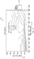
- FIG. 4 is a graph depicting exemplary component durability data or, more specifically, pump cavitation prediction data, according to an aspect of the present disclosure
- FIG. 5 is a diagram of an exemplary pump simulation model, for use with the method of FIG. 3 , according to an aspect of the present disclosure
- FIG. 6 is a diagram of an exemplary transmission simulation model, for use with the method of FIG. 3 , according to an aspect of the present disclosure
- FIG. 7 is a diagram of an exemplary engine simulation model, for use with the method of FIG. 3 , according to an aspect of the present disclosure:
- FIG. 8 is a graph depicting exemplary component durability data or, more specifically, transmission gear life prediction data, according to an aspect of the present disclosure
- FIG. 9 is a graph depicting exemplary component durability data or, more specifically, pump life prediction data, according to an aspect of the present disclosure:
- FIG. 10 is a graph depicting exemplary fuel consumption data or, more specifically, brake specific fuel consumption data, according to an aspect of the present disclosure.
- FIG. 11 is a flow diagram of the primary steps of the method of optimizing operation of the present disclosure.
- FIG. 1 depicts an exemplary site layout according to a well stimulation stage (i.e., hydraulic fracturing stage) of a drilling/mining process, such as after a well has been drilled at the site 10 and the equipment used for drilling removed.
- the site 10 may include a fluid storage tank 12 , a sand storage tank 14 and blending equipment 16 for preparing a fracturing fluid.
- the fracturing fluid which may, for example, include water, sand, and one or more chemicals, may be injected at high pressure through one or more fluid lines 18 to a well head 20 using one or more hydraulic fracturing system(s) 22 .
- a bleed off tank 24 may be provided to receive bleed off liquid or gas from the fluid lines 18 , as is known to those skilled in the art.
- nitrogen which may be beneficial to the hydraulic fracturing process for a variety of reasons, may be stored in tanks 26 , with a pumping system 28 used to supply the nitrogen from the tanks 26 to the fluid lines 18 or well head 20 .
- the hydraulic fracturing process performed at the site 10 may be managed and/or monitored from a single location, such as a data monitoring system 27 , or from multiple locations.
- the data monitoring system 27 may be supported on a van, truck or may be otherwise mobile.
- the data monitoring system 27 may include a display 29 for displaying data for monitoring performance and/or optimizing operation of the hydraulic fracturing systems 22 .
- the data gathered by the data monitoring system 27 may be sent off-board or off-site for monitoring performance and/or performing calculations relative to the hydraulic fracturing site 10 .
- the one or more hydraulic fracturing system(s) 22 may each generally include an engine 30 , or other source of power, a transmission 32 , and a hydraulic fracturing pump 34 .
- a driveshaft 36 may be coupled between the transmission 32 and the hydraulic fracturing pump 34 for transferring torque from the engine 30 to the hydraulic fracturing pump 34 .
- One or more sensors 38 may be positioned and configured to detect or measure one or more physical properties related to operation and/or performance of the various components of the hydraulic fracturing system 22 .
- This equipment e.g., engine 30 , transmission 32 , and hydraulic fracturing pump 34
- This equipment may be mobile, such as supported on a hydraulic fracturing rig 40 , so that it may be more easily transported from site to site.
- a controller 42 including a processor 48 and memory 50 , may be provided, and may be part of, or may communicate with, an advisory system 46 .
- the controller 42 and/or advisory system 46 may reside in whole or in part on the hydraulic fracturing rig 40 , the data monitoring system 27 ( FIG. 1 ), or elsewhere relative to the site 10 . Further, the controller 42 and/or advisory system 46 may be configured to communicate with the sensors 38 and/or various other systems or devices via wired and/or wireless communication lines 44 to monitor and control various aspects of each of the engine 30 , transmission 32 , and hydraulic fracturing pump 34 .
- the controller 42 may be programmed to execute an optimization program 64 .
- the optimization program 64 may receive pump flow and pressure settings, such as those requested by an operator, and may utilize fuel consumption data 54 and component durability data 56 , which may be stored in a database 52 or memory 50 , to identify an optimal transmission gear.
- the component durability data 56 may include transmission gear life prediction data and pump cavitation prediction data 60 .
- various other durability data may also be used.
- a method of operating the hydraulic fracturing system 22 or, more particularly, optimizing operation of the hydraulic fracturing system 22 may include execution of the optimization program 64 , which is illustrated as a flow diagram 70 in FIG. 3 .
- the method may be implemented in whole or in part by the controller 42 , with all or portions of the method running continuously or intermittently, such as at predetermined intervals.
- the method begins at a start, box 72 , and proceeds to box 74 , at which pump flow and pressure settings are received.
- the pump flow and pressure settings may be provided as inputs to an optimizer process, at box 76 .
- the pump cavitation prediction data 60 may be referenced to ensure that the pump flow and pressure settings do not correspond to a potential pump cavitation event.
- the pump cavitation prediction data 60 may include pump speeds 78 along the x-axis and inlet pressure values 80 along the y-axis.
- Curve 82 may separate operating parameters in which a pump cavitation event has occurred or is likely to occur from operation in which a pump cavitation event is not likely to occur.
- the pump cavitation prediction data 60 of FIG. 4 is for cavitation prediction with water, with fluid properties, the curve 82 will change.
- the optimizer process begins.
- the pump flow and pressure settings are received, at box 86 , and gear one is selected at box 88 .
- a single rig process is executed for gear one, at box 90 .
- the single rig process begins at box 92 , and receives as input the pump flow and pressure settings and the gear number for which the analysis is being performed, as shown at box 94 .
- a pump model corresponding to operation of the hydraulic fracturing pump 34 is utilized.
- the pump model shown at 98 in FIG. 5 , receives a pump flow 100 and a pump pressure 102 , and generates a transmission output speed 104 and a transmission output torque 106 , at box 108 .
- a model corresponding to operation of the transmission 32 is utilized.
- the transmission model shown at 112 in FIG. 6 , receives the transmission output speed 104 and the transmission output torque 106 as inputs, and generates a transmission input speed 114 , a transmission input torque 116 , and an engine speed 118 , at box 120 .
- a model corresponding to operation of the engine 30 is called.
- the engine model shown at 124 in FIG. 7 , receives the engine speed 118 and transmission input torque 116 , and generates a brake specific fuel consumption (BSFC) value 126 , an engine speed 128 , and an engine load 130 , all corresponding to gear one. It is shown that, at box 132 , parasitic loads on the engine 30 are also accounted for, and the BSFC value 126 , engine speed 128 , and engine load 130 are all returned, at box 134 .
- BSFC brake specific fuel consumption
- the single rig process ends at box 136 , with the BSFC value 126 being calculated, at box 138 .
- the method determines if all gears have been evaluated, at box 140 , and, if not, the gear number is incremented, at box 142 , and the single rig process is executed again for the next gear, at box 90 .
- the minimum BSFC value 126 and corresponding gear number are selected, at box 144 .
- the gear number, BSFC value 126 , engine speed 128 , and engine load 130 are returned, at box 146 , and the optimizer process ends, at box 148 .
- the optimal transmission gear, and corresponding data, are returned, at box 150 .
- the optimal transmission gear may be analyzed relative to the transmission gear life prediction data 58 , shown in FIG. 8 , which may include days 152 along the x-axis and usage in equivalent hours 154 along the y-axis.
- a curve 156 may represent usage hours 154 corresponding to days 152 for a transmission gear. If the predicted gear life of the optimal transmission gear is outside a desirable range, a different optimal transmission gear may be selected, by returning to the optimizer process, at box 76 .
- the optimal transmission gear is identified and the method ends, at box 158 .
- the optimal transmission gear may be displayed on the operator display 62 of the advisory system and/or the display 29 of the data monitoring system 27 . Additionally, or alternatively, the hydraulic fracturing system 22 may be configured to automatically shift a gear of the transmission 32 to the optimal transmission gear.
- additional component durability data 56 may include pump life prediction data 160 , as shown in FIG. 9 .
- the pump life prediction data 160 may include days 162 along the x-axis and usage in equivalent hours 164 along the y-axis.
- Curve 166 may represent usage hours 164 corresponding to days 162 for the hydraulic fracturing pump 34 .
- Predicted pump life may also be a factor that is considered in the optimization strategy.
- a BSFC map 172 is shown.
- Engine speed 174 is depicted along the x-axis and engine torque 176 is depicted along the y-axis.
- the BSFC map 172 analyzes the fuel efficiency of the engine 30 and generally represents the rate of fuel consumption divided by the power produced. Depicted on the BSFC map 172 are a set of efficiency values 178 corresponding to manual operation and a set of efficiency values 180 corresponding to optimized operation.
- the present disclosure relates generally to a hydraulic fracturing system. More particularly, the present disclosure relates to optimizing operation of the hydraulic fracturing system. Yet further, the present disclosure is applicable to a system and method for identifying an optimal transmission gear based on fuel consumption data and component durability data.
- a hydraulic fracturing system 22 generally includes an engine 30 , transmission 32 , hydraulic fracturing pump 34 and a driveshaft 36 coupled between the transmission 32 and the hydraulic fracturing pump 34 .
- operation of hydraulic fracturing systems 22 including selection of the transmission gear, is done manually.
- the operating performance of the hydraulic fracturing system 22 may be limited by the experience of the operator, without regard to fuel economy or durability.
- a controller 42 including a processor 48 and memory 50 , may be provided, and may be part of, or may communicate with, an advisory system 46 .
- the advisory system 46 or, more specifically, the controller 42 may be configured to execute an optimization program 64 , the primary steps of which are illustrated in a flow diagram 190 of FIG. 11 .
- the optimization program 64 receives pump flow and pressure settings at the controller 42 .
- the controller 42 uses the pump flow and pressure settings, fuel consumption data 54 , and component durability data 56 to identify an optimal transmission gear, at box 196 .
- the optimal transmission gear may be displayed on one of displays 29 or 62 , or otherwise communicated to the operator, at box 198 .
- the disclosed optimization strategy considers durability of various components of the hydraulic fracturing system 22 .
- the optimization strategy provides a means for operating the hydraulic fracturing system 22 in a more fuel efficient manner, while also avoiding operation that may lead to premature damage or failure, and extending the life of the components of the hydraulic fracturing system 22 .
Landscapes
- Engineering & Computer Science (AREA)
- General Engineering & Computer Science (AREA)
- Mechanical Engineering (AREA)
- Life Sciences & Earth Sciences (AREA)
- Mining & Mineral Resources (AREA)
- Geology (AREA)
- Environmental & Geological Engineering (AREA)
- Physics & Mathematics (AREA)
- Combustion & Propulsion (AREA)
- Fluid Mechanics (AREA)
- Chemical & Material Sciences (AREA)
- Computer Hardware Design (AREA)
- General Life Sciences & Earth Sciences (AREA)
- Geochemistry & Mineralogy (AREA)
- Control Of Transmission Device (AREA)
- Operations Research (AREA)
Abstract
Description
Claims (20)
Priority Applications (2)
| Application Number | Priority Date | Filing Date | Title |
|---|---|---|---|
| US15/481,074 US10563649B2 (en) | 2017-04-06 | 2017-04-06 | Hydraulic fracturing system and method for optimizing operation thereof |
| CA3000247A CA3000247A1 (en) | 2017-04-06 | 2018-04-04 | Hydraulic fracturing system and method for optimizing operation thereof |
Applications Claiming Priority (1)
| Application Number | Priority Date | Filing Date | Title |
|---|---|---|---|
| US15/481,074 US10563649B2 (en) | 2017-04-06 | 2017-04-06 | Hydraulic fracturing system and method for optimizing operation thereof |
Publications (2)
| Publication Number | Publication Date |
|---|---|
| US20180291712A1 US20180291712A1 (en) | 2018-10-11 |
| US10563649B2 true US10563649B2 (en) | 2020-02-18 |
Family
ID=63709017
Family Applications (1)
| Application Number | Title | Priority Date | Filing Date |
|---|---|---|---|
| US15/481,074 Active 2038-06-05 US10563649B2 (en) | 2017-04-06 | 2017-04-06 | Hydraulic fracturing system and method for optimizing operation thereof |
Country Status (2)
| Country | Link |
|---|---|
| US (1) | US10563649B2 (en) |
| CA (1) | CA3000247A1 (en) |
Cited By (66)
| Publication number | Priority date | Publication date | Assignee | Title |
|---|---|---|---|---|
| US10954770B1 (en) | 2020-06-09 | 2021-03-23 | Bj Energy Solutions, Llc | Systems and methods for exchanging fracturing components of a hydraulic fracturing unit |
| US10961912B1 (en) | 2019-09-13 | 2021-03-30 | Bj Energy Solutions, Llc | Direct drive unit removal system and associated methods |
| US10961908B1 (en) | 2020-06-05 | 2021-03-30 | Bj Energy Solutions, Llc | Systems and methods to enhance intake air flow to a gas turbine engine of a hydraulic fracturing unit |
| US10961914B1 (en) | 2019-09-13 | 2021-03-30 | BJ Energy Solutions, LLC Houston | Turbine engine exhaust duct system and methods for noise dampening and attenuation |
| US10968837B1 (en) | 2020-05-14 | 2021-04-06 | Bj Energy Solutions, Llc | Systems and methods utilizing turbine compressor discharge for hydrostatic manifold purge |
| US10989180B2 (en) | 2019-09-13 | 2021-04-27 | Bj Energy Solutions, Llc | Power sources and transmission networks for auxiliary equipment onboard hydraulic fracturing units and associated methods |
| US11002189B2 (en) | 2019-09-13 | 2021-05-11 | Bj Energy Solutions, Llc | Mobile gas turbine inlet air conditioning system and associated methods |
| US11015594B2 (en) | 2019-09-13 | 2021-05-25 | Bj Energy Solutions, Llc | Systems and method for use of single mass flywheel alongside torsional vibration damper assembly for single acting reciprocating pump |
| US11015536B2 (en) | 2019-09-13 | 2021-05-25 | Bj Energy Solutions, Llc | Methods and systems for supplying fuel to gas turbine engines |
| US11022526B1 (en) | 2020-06-09 | 2021-06-01 | Bj Energy Solutions, Llc | Systems and methods for monitoring a condition of a fracturing component section of a hydraulic fracturing unit |
| US11028677B1 (en) | 2020-06-22 | 2021-06-08 | Bj Energy Solutions, Llc | Stage profiles for operations of hydraulic systems and associated methods |
| US11066915B1 (en) | 2020-06-09 | 2021-07-20 | Bj Energy Solutions, Llc | Methods for detection and mitigation of well screen out |
| US11109508B1 (en) | 2020-06-05 | 2021-08-31 | Bj Energy Solutions, Llc | Enclosure assembly for enhanced cooling of direct drive unit and related methods |
| US11111768B1 (en) | 2020-06-09 | 2021-09-07 | Bj Energy Solutions, Llc | Drive equipment and methods for mobile fracturing transportation platforms |
| US11125066B1 (en) | 2020-06-22 | 2021-09-21 | Bj Energy Solutions, Llc | Systems and methods to operate a dual-shaft gas turbine engine for hydraulic fracturing |
| US11149533B1 (en) | 2020-06-24 | 2021-10-19 | Bj Energy Solutions, Llc | Systems to monitor, detect, and/or intervene relative to cavitation and pulsation events during a hydraulic fracturing operation |
| US11193360B1 (en) | 2020-07-17 | 2021-12-07 | Bj Energy Solutions, Llc | Methods, systems, and devices to enhance fracturing fluid delivery to subsurface formations during high-pressure fracturing operations |
| US11208880B2 (en) | 2020-05-28 | 2021-12-28 | Bj Energy Solutions, Llc | Bi-fuel reciprocating engine to power direct drive turbine fracturing pumps onboard auxiliary systems and related methods |
| US11208953B1 (en) | 2020-06-05 | 2021-12-28 | Bj Energy Solutions, Llc | Systems and methods to enhance intake air flow to a gas turbine engine of a hydraulic fracturing unit |
| US11220895B1 (en) | 2020-06-24 | 2022-01-11 | Bj Energy Solutions, Llc | Automated diagnostics of electronic instrumentation in a system for fracturing a well and associated methods |
| US11236739B2 (en) | 2019-09-13 | 2022-02-01 | Bj Energy Solutions, Llc | Power sources and transmission networks for auxiliary equipment onboard hydraulic fracturing units and associated methods |
| US11268346B2 (en) | 2019-09-13 | 2022-03-08 | Bj Energy Solutions, Llc | Fuel, communications, and power connection systems |
| US11353117B1 (en) | 2020-01-17 | 2022-06-07 | Vulcan Industrial Holdings, LLC | Valve seat insert system and method |
| US11384756B1 (en) | 2020-08-19 | 2022-07-12 | Vulcan Industrial Holdings, LLC | Composite valve seat system and method |
| US11391374B1 (en) | 2021-01-14 | 2022-07-19 | Vulcan Industrial Holdings, LLC | Dual ring stuffing box |
| US11408794B2 (en) | 2019-09-13 | 2022-08-09 | Bj Energy Solutions, Llc | Fuel, communications, and power connection systems and related methods |
| US11415125B2 (en) | 2020-06-23 | 2022-08-16 | Bj Energy Solutions, Llc | Systems for utilization of a hydraulic fracturing unit profile to operate hydraulic fracturing units |
| US11421679B1 (en) | 2020-06-30 | 2022-08-23 | Vulcan Industrial Holdings, LLC | Packing assembly with threaded sleeve for interaction with an installation tool |
| US11421680B1 (en) | 2020-06-30 | 2022-08-23 | Vulcan Industrial Holdings, LLC | Packing bore wear sleeve retainer system |
| US11428165B2 (en) | 2020-05-15 | 2022-08-30 | Bj Energy Solutions, Llc | Onboard heater of auxiliary systems using exhaust gases and associated methods |
| US11434900B1 (en) | 2022-04-25 | 2022-09-06 | Vulcan Industrial Holdings, LLC | Spring controlling valve |
| US11473413B2 (en) | 2020-06-23 | 2022-10-18 | Bj Energy Solutions, Llc | Systems and methods to autonomously operate hydraulic fracturing units |
| US11560845B2 (en) | 2019-05-15 | 2023-01-24 | Bj Energy Solutions, Llc | Mobile gas turbine inlet air conditioning system and associated methods |
| USD980876S1 (en) | 2020-08-21 | 2023-03-14 | Vulcan Industrial Holdings, LLC | Fluid end for a pumping system |
| US11608725B2 (en) | 2019-09-13 | 2023-03-21 | Bj Energy Solutions, Llc | Methods and systems for operating a fleet of pumps |
| US11624326B2 (en) | 2017-05-21 | 2023-04-11 | Bj Energy Solutions, Llc | Methods and systems for supplying fuel to gas turbine engines |
| US11635074B2 (en) | 2020-05-12 | 2023-04-25 | Bj Energy Solutions, Llc | Cover for fluid systems and related methods |
| US11639654B2 (en) | 2021-05-24 | 2023-05-02 | Bj Energy Solutions, Llc | Hydraulic fracturing pumps to enhance flow of fracturing fluid into wellheads and related methods |
| USD986928S1 (en) | 2020-08-21 | 2023-05-23 | Vulcan Industrial Holdings, LLC | Fluid end for a pumping system |
| USD997992S1 (en) | 2020-08-21 | 2023-09-05 | Vulcan Industrial Holdings, LLC | Fluid end for a pumping system |
| US11746634B2 (en) | 2022-01-18 | 2023-09-05 | Caterpillar Inc. | Optimizing fuel consumption and emissions of a multi-rig hydraulic fracturing system |
| US11746635B1 (en) | 2022-03-11 | 2023-09-05 | Caterpillar Inc. | Optimizing operations of a hydraulic fracturing system |
| US11753911B1 (en) | 2022-03-11 | 2023-09-12 | Caterpillar Inc. | Controlling fluid pressure at a well head based on an operation schedule |
| US11802468B2 (en) | 2022-01-24 | 2023-10-31 | Caterpillar Inc. | Asymmetric power management and load management |
| US11808139B2 (en) | 2022-01-21 | 2023-11-07 | Caterpillar Inc. | Monitoring ramp-up pressure of a pump |
| US11859480B2 (en) | 2022-03-11 | 2024-01-02 | Caterpillar Inc. | Controlling fluid pressures at multiple well heads for continuous pumping |
| US11867118B2 (en) | 2019-09-13 | 2024-01-09 | Bj Energy Solutions, Llc | Methods and systems for supplying fuel to gas turbine engines |
| US11920684B1 (en) | 2022-05-17 | 2024-03-05 | Vulcan Industrial Holdings, LLC | Mechanically or hybrid mounted valve seat |
| US11933153B2 (en) | 2020-06-22 | 2024-03-19 | Bj Energy Solutions, Llc | Systems and methods to operate hydraulic fracturing units using automatic flow rate and/or pressure control |
| US11939853B2 (en) | 2020-06-22 | 2024-03-26 | Bj Energy Solutions, Llc | Systems and methods providing a configurable staged rate increase function to operate hydraulic fracturing units |
| US12049801B2 (en) | 2022-03-11 | 2024-07-30 | Caterpillar Inc. | Controlling operations of a hydraulic fracturing system to cause or prevent an occurrence of one or more events |
| US12049889B2 (en) | 2020-06-30 | 2024-07-30 | Vulcan Industrial Holdings, LLC | Packing bore wear sleeve retainer system |
| US12055221B2 (en) | 2021-01-14 | 2024-08-06 | Vulcan Industrial Holdings, LLC | Dual ring stuffing box |
| US12065968B2 (en) | 2019-09-13 | 2024-08-20 | BJ Energy Solutions, Inc. | Systems and methods for hydraulic fracturing |
| US12140240B1 (en) | 2022-01-19 | 2024-11-12 | Vulcan Industrial Holdings, LLC | Gradient material structures and methods of forming the same |
| USD1061623S1 (en) | 2022-08-03 | 2025-02-11 | Vulcan Industrial Holdings, LLC | Fluid end for a pumping system |
| US12281964B2 (en) | 2019-09-13 | 2025-04-22 | Bj Energy Solutions, Llc | Fuel, communications, and power connection systems and related methods |
| US12292121B2 (en) | 2023-08-10 | 2025-05-06 | Vulcan Industrial Holdings, LLC | Valve member including cavity, and related assemblies, systems, and methods |
| US12292120B1 (en) | 2021-02-23 | 2025-05-06 | Vulcan Industrial Holdings, LLC | System and method for valve assembly |
| US12297922B1 (en) | 2022-03-04 | 2025-05-13 | Vulcan Industrial Holdings, LLC | Valve seat with embedded structure and related methods |
| US12338772B2 (en) | 2019-09-13 | 2025-06-24 | Bj Energy Solutions, Llc | Systems, assemblies, and methods to enhance intake air flow to a gas turbine engine of a hydraulic fracturing unit |
| US12345332B2 (en) | 2021-08-18 | 2025-07-01 | Vulcan Industrial Holdings, LLC | Self-locking plug |
| US12366245B1 (en) | 2020-08-27 | 2025-07-22 | Vulcan Industrial Holdings, LLC | Connecting rod assembly for reciprocating pump |
| US12378864B2 (en) | 2021-10-25 | 2025-08-05 | Bj Energy Solutions, Llc | Systems and methods to reduce acoustic resonance or disrupt standing wave formation in a fluid manifold of a high-pressure fracturing system |
| US12510164B1 (en) | 2021-08-18 | 2025-12-30 | Vulcan Industrial Holdings, LLC | Sleeved fluid end |
| US12516592B2 (en) | 2022-01-18 | 2026-01-06 | Caterpillar Inc. | Optimizing operation of a mixed fleet of hydraulic fracturing rigs |
Citations (27)
| Publication number | Priority date | Publication date | Assignee | Title |
|---|---|---|---|---|
| US2361086A (en) * | 1942-07-20 | 1944-10-24 | William L Carlson | Automatic clutch controlled prime mover |
| US3981618A (en) * | 1975-02-14 | 1976-09-21 | Grumman Aerospace Corporation | Method and apparatus for preventing pump cavitation |
| US4925370A (en) * | 1988-12-09 | 1990-05-15 | Tallarita Domenic A | Electric motor driven pump with an automatic transmission |
| US5474428A (en) * | 1992-12-10 | 1995-12-12 | Honda Giken Kogyo Kabushiki Kaisha | Oil pump driving device for transmission |
| US5848877A (en) * | 1997-05-23 | 1998-12-15 | Butterworth Jetting Systems, Inc. | Water blasting system with improved pressure control and method |
| US6655922B1 (en) * | 2001-08-10 | 2003-12-02 | Rockwell Automation Technologies, Inc. | System and method for detecting and diagnosing pump cavitation |
| US6663349B1 (en) * | 2001-03-02 | 2003-12-16 | Reliance Electric Technologies, Llc | System and method for controlling pump cavitation and blockage |
| US20060245934A1 (en) * | 2005-04-29 | 2006-11-02 | Caterpillar Inc. | System and method for controlling a fluid pump |
| US20090312885A1 (en) | 2008-06-11 | 2009-12-17 | Buiel Edward R | Management system for drilling rig power supply and storage system |
| US20100174496A1 (en) * | 2006-07-07 | 2010-07-08 | Sarmad Adnan | Pump integrity monitoring |
| US20100300683A1 (en) * | 2009-05-28 | 2010-12-02 | Halliburton Energy Services, Inc. | Real Time Pump Monitoring |
| US7901314B2 (en) * | 2006-09-13 | 2011-03-08 | Schlumberger Technology Corporation | Transmission system for pump drive |
| US7987916B2 (en) * | 2008-04-09 | 2011-08-02 | Hale Products, Inc. | Integrated controls for a fire suppression system |
| US8506267B2 (en) * | 2007-09-10 | 2013-08-13 | Schlumberger Technology Corporation | Pump assembly |
| US20130234515A1 (en) * | 2010-05-28 | 2013-09-12 | Scott G. Boone | Rig fuel management systems and methods |
| US8543245B2 (en) * | 2009-11-20 | 2013-09-24 | Halliburton Energy Services, Inc. | Systems and methods for specifying an operational parameter for a pumping system |
| US20140219824A1 (en) * | 2013-02-06 | 2014-08-07 | Baker Hughes Incorporated | Pump system and method thereof |
| US20140229120A1 (en) * | 2011-07-08 | 2014-08-14 | Schlumberger Technology Corporation | System and method for determining a health condition of wellsite equipment |
| US20150369351A1 (en) * | 2014-06-23 | 2015-12-24 | Voith Patent Gmbh | Pumping device |
| US20160194942A1 (en) | 2015-01-02 | 2016-07-07 | General Electric Company | System and method for power management of pumping system |
| US20160195082A1 (en) * | 2015-01-02 | 2016-07-07 | General Electric Company | System and method for health management of pumping system |
| US9410546B2 (en) * | 2014-08-12 | 2016-08-09 | Baker Hughes Incorporated | Reciprocating pump cavitation detection and avoidance |
| US20160230512A1 (en) * | 2013-10-15 | 2016-08-11 | Halliburton Energy Services, Inc. | Optimization of fuel consumption in equipment used in well site operations |
| US20160265457A1 (en) | 2014-02-26 | 2016-09-15 | Halliburton Energy Services, Inc. | Optimizing diesel fuel consumption for dual-fuel engines |
| US20170082101A1 (en) * | 2015-09-17 | 2017-03-23 | Schlumberger Technology Corporation | Apparatus and Methods for Identifying Defective Pumps |
| US20170114625A1 (en) * | 2014-06-13 | 2017-04-27 | Lord Corporation | System and method for monitoring component service life |
| US20170234308A1 (en) * | 2016-02-11 | 2017-08-17 | S.P.M. Flow Control, Inc. | Transmission for pump such as hydraulic fracturing pump |
-
2017
- 2017-04-06 US US15/481,074 patent/US10563649B2/en active Active
-
2018
- 2018-04-04 CA CA3000247A patent/CA3000247A1/en active Pending
Patent Citations (27)
| Publication number | Priority date | Publication date | Assignee | Title |
|---|---|---|---|---|
| US2361086A (en) * | 1942-07-20 | 1944-10-24 | William L Carlson | Automatic clutch controlled prime mover |
| US3981618A (en) * | 1975-02-14 | 1976-09-21 | Grumman Aerospace Corporation | Method and apparatus for preventing pump cavitation |
| US4925370A (en) * | 1988-12-09 | 1990-05-15 | Tallarita Domenic A | Electric motor driven pump with an automatic transmission |
| US5474428A (en) * | 1992-12-10 | 1995-12-12 | Honda Giken Kogyo Kabushiki Kaisha | Oil pump driving device for transmission |
| US5848877A (en) * | 1997-05-23 | 1998-12-15 | Butterworth Jetting Systems, Inc. | Water blasting system with improved pressure control and method |
| US6663349B1 (en) * | 2001-03-02 | 2003-12-16 | Reliance Electric Technologies, Llc | System and method for controlling pump cavitation and blockage |
| US6655922B1 (en) * | 2001-08-10 | 2003-12-02 | Rockwell Automation Technologies, Inc. | System and method for detecting and diagnosing pump cavitation |
| US20060245934A1 (en) * | 2005-04-29 | 2006-11-02 | Caterpillar Inc. | System and method for controlling a fluid pump |
| US20100174496A1 (en) * | 2006-07-07 | 2010-07-08 | Sarmad Adnan | Pump integrity monitoring |
| US7901314B2 (en) * | 2006-09-13 | 2011-03-08 | Schlumberger Technology Corporation | Transmission system for pump drive |
| US8506267B2 (en) * | 2007-09-10 | 2013-08-13 | Schlumberger Technology Corporation | Pump assembly |
| US7987916B2 (en) * | 2008-04-09 | 2011-08-02 | Hale Products, Inc. | Integrated controls for a fire suppression system |
| US20090312885A1 (en) | 2008-06-11 | 2009-12-17 | Buiel Edward R | Management system for drilling rig power supply and storage system |
| US20100300683A1 (en) * | 2009-05-28 | 2010-12-02 | Halliburton Energy Services, Inc. | Real Time Pump Monitoring |
| US8543245B2 (en) * | 2009-11-20 | 2013-09-24 | Halliburton Energy Services, Inc. | Systems and methods for specifying an operational parameter for a pumping system |
| US20130234515A1 (en) * | 2010-05-28 | 2013-09-12 | Scott G. Boone | Rig fuel management systems and methods |
| US20140229120A1 (en) * | 2011-07-08 | 2014-08-14 | Schlumberger Technology Corporation | System and method for determining a health condition of wellsite equipment |
| US20140219824A1 (en) * | 2013-02-06 | 2014-08-07 | Baker Hughes Incorporated | Pump system and method thereof |
| US20160230512A1 (en) * | 2013-10-15 | 2016-08-11 | Halliburton Energy Services, Inc. | Optimization of fuel consumption in equipment used in well site operations |
| US20160265457A1 (en) | 2014-02-26 | 2016-09-15 | Halliburton Energy Services, Inc. | Optimizing diesel fuel consumption for dual-fuel engines |
| US20170114625A1 (en) * | 2014-06-13 | 2017-04-27 | Lord Corporation | System and method for monitoring component service life |
| US20150369351A1 (en) * | 2014-06-23 | 2015-12-24 | Voith Patent Gmbh | Pumping device |
| US9410546B2 (en) * | 2014-08-12 | 2016-08-09 | Baker Hughes Incorporated | Reciprocating pump cavitation detection and avoidance |
| US20160195082A1 (en) * | 2015-01-02 | 2016-07-07 | General Electric Company | System and method for health management of pumping system |
| US20160194942A1 (en) | 2015-01-02 | 2016-07-07 | General Electric Company | System and method for power management of pumping system |
| US20170082101A1 (en) * | 2015-09-17 | 2017-03-23 | Schlumberger Technology Corporation | Apparatus and Methods for Identifying Defective Pumps |
| US20170234308A1 (en) * | 2016-02-11 | 2017-08-17 | S.P.M. Flow Control, Inc. | Transmission for pump such as hydraulic fracturing pump |
Cited By (196)
| Publication number | Priority date | Publication date | Assignee | Title |
|---|---|---|---|---|
| US11624326B2 (en) | 2017-05-21 | 2023-04-11 | Bj Energy Solutions, Llc | Methods and systems for supplying fuel to gas turbine engines |
| US11560845B2 (en) | 2019-05-15 | 2023-01-24 | Bj Energy Solutions, Llc | Mobile gas turbine inlet air conditioning system and associated methods |
| US11415056B1 (en) | 2019-09-13 | 2022-08-16 | Bj Energy Solutions, Llc | Turbine engine exhaust duct system and methods for noise dampening and attenuation |
| US10961912B1 (en) | 2019-09-13 | 2021-03-30 | Bj Energy Solutions, Llc | Direct drive unit removal system and associated methods |
| US12516632B2 (en) | 2019-09-13 | 2026-01-06 | Bj Energy Solutions, Llc | Turbine engine exhaust duct system and methods for noise dampening and attenuation |
| US10961914B1 (en) | 2019-09-13 | 2021-03-30 | BJ Energy Solutions, LLC Houston | Turbine engine exhaust duct system and methods for noise dampening and attenuation |
| US12510028B2 (en) | 2019-09-13 | 2025-12-30 | Bj Energy Solutions, Llc | Direct drive unit removal system and associated methods |
| US10982596B1 (en) | 2019-09-13 | 2021-04-20 | Bj Energy Solutions, Llc | Direct drive unit removal system and associated methods |
| US10989180B2 (en) | 2019-09-13 | 2021-04-27 | Bj Energy Solutions, Llc | Power sources and transmission networks for auxiliary equipment onboard hydraulic fracturing units and associated methods |
| US11002189B2 (en) | 2019-09-13 | 2021-05-11 | Bj Energy Solutions, Llc | Mobile gas turbine inlet air conditioning system and associated methods |
| US11015594B2 (en) | 2019-09-13 | 2021-05-25 | Bj Energy Solutions, Llc | Systems and method for use of single mass flywheel alongside torsional vibration damper assembly for single acting reciprocating pump |
| US11015536B2 (en) | 2019-09-13 | 2021-05-25 | Bj Energy Solutions, Llc | Methods and systems for supplying fuel to gas turbine engines |
| US12510070B2 (en) | 2019-09-13 | 2025-12-30 | Bj Energy Solutions, Llc | Systems and method for use of single mass flywheel alongside torsional vibration damper assembly for single acting reciprocating pump |
| US12497879B2 (en) | 2019-09-13 | 2025-12-16 | Bj Energy Solutions, Llc | Power sources and transmission networks for auxiliary equipment onboard hydraulic fracturing units and associated methods |
| US12467348B2 (en) | 2019-09-13 | 2025-11-11 | Bj Energy Solutions, Llc | Methods and systems for operating a fleet of pumps |
| US11060455B1 (en) | 2019-09-13 | 2021-07-13 | Bj Energy Solutions, Llc | Mobile gas turbine inlet air conditioning system and associated methods |
| US12338772B2 (en) | 2019-09-13 | 2025-06-24 | Bj Energy Solutions, Llc | Systems, assemblies, and methods to enhance intake air flow to a gas turbine engine of a hydraulic fracturing unit |
| US12281964B2 (en) | 2019-09-13 | 2025-04-22 | Bj Energy Solutions, Llc | Fuel, communications, and power connection systems and related methods |
| US11092152B2 (en) | 2019-09-13 | 2021-08-17 | Bj Energy Solutions, Llc | Systems and method for use of single mass flywheel alongside torsional vibration damper assembly for single acting reciprocating pump |
| US11098651B1 (en) | 2019-09-13 | 2021-08-24 | Bj Energy Solutions, Llc | Turbine engine exhaust duct system and methods for noise dampening and attenuation |
| US12276577B2 (en) | 2019-09-13 | 2025-04-15 | Bj Energy Solutions, Llc | Fuel, communications, and power connection systems and related methods |
| US12092100B2 (en) | 2019-09-13 | 2024-09-17 | Bj Energy Solutions, Llc | Systems and method for use of single mass flywheel alongside torsional vibration damper assembly for single acting reciprocating pump |
| US12065968B2 (en) | 2019-09-13 | 2024-08-20 | BJ Energy Solutions, Inc. | Systems and methods for hydraulic fracturing |
| US12049808B2 (en) | 2019-09-13 | 2024-07-30 | Bj Energy Solutions, Llc | Methods and systems for operating a fleet of pumps |
| US11149726B1 (en) | 2019-09-13 | 2021-10-19 | Bj Energy Solutions, Llc | Systems and method for use of single mass flywheel alongside torsional vibration damper assembly for single acting reciprocating pump |
| US11971028B2 (en) | 2019-09-13 | 2024-04-30 | Bj Energy Solutions, Llc | Systems and method for use of single mass flywheel alongside torsional vibration damper assembly for single acting reciprocating pump |
| US11156159B1 (en) | 2019-09-13 | 2021-10-26 | Bj Energy Solutions, Llc | Mobile gas turbine inlet air conditioning system and associated methods |
| US11867118B2 (en) | 2019-09-13 | 2024-01-09 | Bj Energy Solutions, Llc | Methods and systems for supplying fuel to gas turbine engines |
| US11859482B2 (en) | 2019-09-13 | 2024-01-02 | Bj Energy Solutions, Llc | Power sources and transmission networks for auxiliary equipment onboard hydraulic fracturing units and associated methods |
| US11852001B2 (en) * | 2019-09-13 | 2023-12-26 | Bj Energy Solutions, Llc | Methods and systems for operating a fleet of pumps |
| US11767791B2 (en) | 2019-09-13 | 2023-09-26 | Bj Energy Solutions, Llc | Mobile gas turbine inlet air conditioning system and associated methods |
| US11761846B2 (en) | 2019-09-13 | 2023-09-19 | Bj Energy Solutions, Llc | Fuel, communications, and power connection systems and related methods |
| US11725583B2 (en) | 2019-09-13 | 2023-08-15 | Bj Energy Solutions, Llc | Mobile gas turbine inlet air conditioning system and associated methods |
| US11719234B2 (en) | 2019-09-13 | 2023-08-08 | Bj Energy Solutions, Llc | Systems and method for use of single mass flywheel alongside torsional vibration damper assembly for single acting reciprocating pump |
| US20230184074A1 (en) * | 2019-09-13 | 2023-06-15 | Bj Energy Solutions, Llc | Methods and systems for operating a fleet of pumps |
| US11655763B1 (en) | 2019-09-13 | 2023-05-23 | Bj Energy Solutions, Llc | Direct drive unit removal system and associated methods |
| US11236739B2 (en) | 2019-09-13 | 2022-02-01 | Bj Energy Solutions, Llc | Power sources and transmission networks for auxiliary equipment onboard hydraulic fracturing units and associated methods |
| US11649766B1 (en) | 2019-09-13 | 2023-05-16 | Bj Energy Solutions, Llc | Mobile gas turbine inlet air conditioning system and associated methods |
| US11629584B2 (en) | 2019-09-13 | 2023-04-18 | Bj Energy Solutions, Llc | Power sources and transmission networks for auxiliary equipment onboard hydraulic fracturing units and associated methods |
| US11268346B2 (en) | 2019-09-13 | 2022-03-08 | Bj Energy Solutions, Llc | Fuel, communications, and power connection systems |
| US11619122B2 (en) | 2019-09-13 | 2023-04-04 | Bj Energy Solutions, Llc | Methods and systems for operating a fleet of pumps |
| US11280266B2 (en) | 2019-09-13 | 2022-03-22 | Bj Energy Solutions, Llc | Mobile gas turbine inlet air conditioning system and associated methods |
| US11280331B2 (en) | 2019-09-13 | 2022-03-22 | Bj Energy Solutions, Llc | Systems and method for use of single mass flywheel alongside torsional vibration damper assembly for single acting reciprocating pump |
| US11287350B2 (en) | 2019-09-13 | 2022-03-29 | Bj Energy Solutions, Llc | Fuel, communications, and power connection methods |
| US11613980B2 (en) | 2019-09-13 | 2023-03-28 | Bj Energy Solutions, Llc | Methods and systems for operating a fleet of pumps |
| US11608725B2 (en) | 2019-09-13 | 2023-03-21 | Bj Energy Solutions, Llc | Methods and systems for operating a fleet of pumps |
| US11604113B2 (en) | 2019-09-13 | 2023-03-14 | Bj Energy Solutions, Llc | Fuel, communications, and power connection systems and related methods |
| US11319878B2 (en) | 2019-09-13 | 2022-05-03 | Bj Energy Solutions, Llc | Direct drive unit removal system and associated methods |
| US11598263B2 (en) | 2019-09-13 | 2023-03-07 | Bj Energy Solutions, Llc | Mobile gas turbine inlet air conditioning system and associated methods |
| US11578660B1 (en) | 2019-09-13 | 2023-02-14 | Bj Energy Solutions, Llc | Direct drive unit removal system and associated methods |
| US11346280B1 (en) | 2019-09-13 | 2022-05-31 | Bj Energy Solutions, Llc | Direct drive unit removal system and associated methods |
| US11560848B2 (en) | 2019-09-13 | 2023-01-24 | Bj Energy Solutions, Llc | Methods for noise dampening and attenuation of turbine engine |
| US11555756B2 (en) | 2019-09-13 | 2023-01-17 | Bj Energy Solutions, Llc | Fuel, communications, and power connection systems and related methods |
| US11530602B2 (en) | 2019-09-13 | 2022-12-20 | Bj Energy Solutions, Llc | Power sources and transmission networks for auxiliary equipment onboard hydraulic fracturing units and associated methods |
| US11512642B1 (en) | 2019-09-13 | 2022-11-29 | Bj Energy Solutions, Llc | Direct drive unit removal system and associated methods |
| US11473503B1 (en) | 2019-09-13 | 2022-10-18 | Bj Energy Solutions, Llc | Direct drive unit removal system and associated methods |
| US11473997B2 (en) | 2019-09-13 | 2022-10-18 | Bj Energy Solutions, Llc | Fuel, communications, and power connection systems and related methods |
| US11401865B1 (en) | 2019-09-13 | 2022-08-02 | Bj Energy Solutions, Llc | Direct drive unit removal system and associated methods |
| US11460368B2 (en) | 2019-09-13 | 2022-10-04 | Bj Energy Solutions, Llc | Fuel, communications, and power connection systems and related methods |
| US11408794B2 (en) | 2019-09-13 | 2022-08-09 | Bj Energy Solutions, Llc | Fuel, communications, and power connection systems and related methods |
| US11459954B2 (en) | 2019-09-13 | 2022-10-04 | Bj Energy Solutions, Llc | Turbine engine exhaust duct system and methods for noise dampening and attenuation |
| US11353117B1 (en) | 2020-01-17 | 2022-06-07 | Vulcan Industrial Holdings, LLC | Valve seat insert system and method |
| US11635074B2 (en) | 2020-05-12 | 2023-04-25 | Bj Energy Solutions, Llc | Cover for fluid systems and related methods |
| US12404856B2 (en) | 2020-05-12 | 2025-09-02 | Bj Energy Solutions, Llc | Cover for fluid systems and related methods |
| US11708829B2 (en) | 2020-05-12 | 2023-07-25 | Bj Energy Solutions, Llc | Cover for fluid systems and related methods |
| US10968837B1 (en) | 2020-05-14 | 2021-04-06 | Bj Energy Solutions, Llc | Systems and methods utilizing turbine compressor discharge for hydrostatic manifold purge |
| US11898504B2 (en) | 2020-05-14 | 2024-02-13 | Bj Energy Solutions, Llc | Systems and methods utilizing turbine compressor discharge for hydrostatic manifold purge |
| US11428165B2 (en) | 2020-05-15 | 2022-08-30 | Bj Energy Solutions, Llc | Onboard heater of auxiliary systems using exhaust gases and associated methods |
| US11698028B2 (en) | 2020-05-15 | 2023-07-11 | Bj Energy Solutions, Llc | Onboard heater of auxiliary systems using exhaust gases and associated methods |
| US11624321B2 (en) | 2020-05-15 | 2023-04-11 | Bj Energy Solutions, Llc | Onboard heater of auxiliary systems using exhaust gases and associated methods |
| US11434820B2 (en) | 2020-05-15 | 2022-09-06 | Bj Energy Solutions, Llc | Onboard heater of auxiliary systems using exhaust gases and associated methods |
| US11542868B2 (en) | 2020-05-15 | 2023-01-03 | Bj Energy Solutions, Llc | Onboard heater of auxiliary systems using exhaust gases and associated methods |
| US11959419B2 (en) | 2020-05-15 | 2024-04-16 | Bj Energy Solutions, Llc | Onboard heater of auxiliary systems using exhaust gases and associated methods |
| US11208880B2 (en) | 2020-05-28 | 2021-12-28 | Bj Energy Solutions, Llc | Bi-fuel reciprocating engine to power direct drive turbine fracturing pumps onboard auxiliary systems and related methods |
| US11365616B1 (en) | 2020-05-28 | 2022-06-21 | Bj Energy Solutions, Llc | Bi-fuel reciprocating engine to power direct drive turbine fracturing pumps onboard auxiliary systems and related methods |
| US11313213B2 (en) | 2020-05-28 | 2022-04-26 | Bj Energy Solutions, Llc | Bi-fuel reciprocating engine to power direct drive turbine fracturing pumps onboard auxiliary systems and related methods |
| US11603745B2 (en) | 2020-05-28 | 2023-03-14 | Bj Energy Solutions, Llc | Bi-fuel reciprocating engine to power direct drive turbine fracturing pumps onboard auxiliary systems and related methods |
| US11814940B2 (en) | 2020-05-28 | 2023-11-14 | Bj Energy Solutions Llc | Bi-fuel reciprocating engine to power direct drive turbine fracturing pumps onboard auxiliary systems and related methods |
| US11627683B2 (en) | 2020-06-05 | 2023-04-11 | Bj Energy Solutions, Llc | Enclosure assembly for enhanced cooling of direct drive unit and related methods |
| US11208953B1 (en) | 2020-06-05 | 2021-12-28 | Bj Energy Solutions, Llc | Systems and methods to enhance intake air flow to a gas turbine engine of a hydraulic fracturing unit |
| US11891952B2 (en) | 2020-06-05 | 2024-02-06 | Bj Energy Solutions, Llc | Systems and methods to enhance intake air flow to a gas turbine engine of a hydraulic fracturing unit |
| US11378008B2 (en) | 2020-06-05 | 2022-07-05 | Bj Energy Solutions, Llc | Systems and methods to enhance intake air flow to a gas turbine engine of a hydraulic fracturing unit |
| US12408291B2 (en) | 2020-06-05 | 2025-09-02 | Bj Energy Solutions, Llc | Enclosure assembly for enhanced cooling of direct drive unit and related methods |
| US11598264B2 (en) | 2020-06-05 | 2023-03-07 | Bj Energy Solutions, Llc | Systems and methods to enhance intake air flow to a gas turbine engine of a hydraulic fracturing unit |
| US11723171B2 (en) | 2020-06-05 | 2023-08-08 | Bj Energy Solutions, Llc | Enclosure assembly for enhanced cooling of direct drive unit and related methods |
| US11129295B1 (en) | 2020-06-05 | 2021-09-21 | Bj Energy Solutions, Llc | Enclosure assembly for enhanced cooling of direct drive unit and related methods |
| US11300050B2 (en) | 2020-06-05 | 2022-04-12 | Bj Energy Solutions, Llc | Systems and methods to enhance intake air flow to a gas turbine engine of a hydraulic fracturing unit |
| US11746698B2 (en) | 2020-06-05 | 2023-09-05 | Bj Energy Solutions, Llc | Systems and methods to enhance intake air flow to a gas turbine engine of a hydraulic fracturing unit |
| US10961908B1 (en) | 2020-06-05 | 2021-03-30 | Bj Energy Solutions, Llc | Systems and methods to enhance intake air flow to a gas turbine engine of a hydraulic fracturing unit |
| US11109508B1 (en) | 2020-06-05 | 2021-08-31 | Bj Energy Solutions, Llc | Enclosure assembly for enhanced cooling of direct drive unit and related methods |
| US11111768B1 (en) | 2020-06-09 | 2021-09-07 | Bj Energy Solutions, Llc | Drive equipment and methods for mobile fracturing transportation platforms |
| US11066915B1 (en) | 2020-06-09 | 2021-07-20 | Bj Energy Solutions, Llc | Methods for detection and mitigation of well screen out |
| US11022526B1 (en) | 2020-06-09 | 2021-06-01 | Bj Energy Solutions, Llc | Systems and methods for monitoring a condition of a fracturing component section of a hydraulic fracturing unit |
| US11319791B2 (en) | 2020-06-09 | 2022-05-03 | Bj Energy Solutions, Llc | Methods and systems for detection and mitigation of well screen out |
| US11339638B1 (en) | 2020-06-09 | 2022-05-24 | Bj Energy Solutions, Llc | Systems and methods for exchanging fracturing components of a hydraulic fracturing unit |
| US12305495B2 (en) | 2020-06-09 | 2025-05-20 | Bj Energy Solutions, Llc | Systems and methods for exchanging fracturing components of a hydraulic fracturing unit |
| US12385379B2 (en) | 2020-06-09 | 2025-08-12 | Bj Energy Solutions, Llc | Methods for detection and mitigation of well screen out |
| US11208881B1 (en) | 2020-06-09 | 2021-12-28 | Bj Energy Solutions, Llc | Methods and systems for detection and mitigation of well screen out |
| US11566506B2 (en) | 2020-06-09 | 2023-01-31 | Bj Energy Solutions, Llc | Methods for detection and mitigation of well screen out |
| US11261717B2 (en) | 2020-06-09 | 2022-03-01 | Bj Energy Solutions, Llc | Systems and methods for exchanging fracturing components of a hydraulic fracturing unit |
| US10954770B1 (en) | 2020-06-09 | 2021-03-23 | Bj Energy Solutions, Llc | Systems and methods for exchanging fracturing components of a hydraulic fracturing unit |
| US11015423B1 (en) | 2020-06-09 | 2021-05-25 | Bj Energy Solutions, Llc | Systems and methods for exchanging fracturing components of a hydraulic fracturing unit |
| US11629583B2 (en) | 2020-06-09 | 2023-04-18 | Bj Energy Solutions, Llc | Systems and methods for exchanging fracturing components of a hydraulic fracturing unit |
| US11085281B1 (en) | 2020-06-09 | 2021-08-10 | Bj Energy Solutions, Llc | Systems and methods for exchanging fracturing components of a hydraulic fracturing unit |
| US11512570B2 (en) | 2020-06-09 | 2022-11-29 | Bj Energy Solutions, Llc | Systems and methods for exchanging fracturing components of a hydraulic fracturing unit |
| US11174716B1 (en) | 2020-06-09 | 2021-11-16 | Bj Energy Solutions, Llc | Drive equipment and methods for mobile fracturing transportation platforms |
| US11867046B2 (en) | 2020-06-09 | 2024-01-09 | Bj Energy Solutions, Llc | Systems and methods for exchanging fracturing components of a hydraulic fracturing unit |
| US11643915B2 (en) | 2020-06-09 | 2023-05-09 | Bj Energy Solutions, Llc | Drive equipment and methods for mobile fracturing transportation platforms |
| US11939854B2 (en) | 2020-06-09 | 2024-03-26 | Bj Energy Solutions, Llc | Methods for detection and mitigation of well screen out |
| US12286874B2 (en) | 2020-06-22 | 2025-04-29 | Bj Energy Solutions, Llc | Systems and methods to operate hydraulic fracturing units using automatic flow rate and/or pressure control |
| US11898429B2 (en) | 2020-06-22 | 2024-02-13 | Bj Energy Solutions, Llc | Systems and methods to operate a dual-shaft gas turbine engine for hydraulic fracturing |
| US11236598B1 (en) | 2020-06-22 | 2022-02-01 | Bj Energy Solutions, Llc | Stage profiles for operations of hydraulic systems and associated methods |
| US11952878B2 (en) | 2020-06-22 | 2024-04-09 | Bj Energy Solutions, Llc | Stage profiles for operations of hydraulic systems and associated methods |
| US11939853B2 (en) | 2020-06-22 | 2024-03-26 | Bj Energy Solutions, Llc | Systems and methods providing a configurable staged rate increase function to operate hydraulic fracturing units |
| US11933153B2 (en) | 2020-06-22 | 2024-03-19 | Bj Energy Solutions, Llc | Systems and methods to operate hydraulic fracturing units using automatic flow rate and/or pressure control |
| US11408263B2 (en) | 2020-06-22 | 2022-08-09 | Bj Energy Solutions, Llc | Systems and methods to operate a dual-shaft gas turbine engine for hydraulic fracturing |
| US11208879B1 (en) | 2020-06-22 | 2021-12-28 | Bj Energy Solutions, Llc | Stage profiles for operations of hydraulic systems and associated methods |
| US11639655B2 (en) | 2020-06-22 | 2023-05-02 | Bj Energy Solutions, Llc | Systems and methods to operate a dual-shaft gas turbine engine for hydraulic fracturing |
| US11028677B1 (en) | 2020-06-22 | 2021-06-08 | Bj Energy Solutions, Llc | Stage profiles for operations of hydraulic systems and associated methods |
| US11125066B1 (en) | 2020-06-22 | 2021-09-21 | Bj Energy Solutions, Llc | Systems and methods to operate a dual-shaft gas turbine engine for hydraulic fracturing |
| US11572774B2 (en) | 2020-06-22 | 2023-02-07 | Bj Energy Solutions, Llc | Systems and methods to operate a dual-shaft gas turbine engine for hydraulic fracturing |
| US12326075B2 (en) | 2020-06-22 | 2025-06-10 | Bj Energy Solutions, Llc | Stage profiles for operations of hydraulic systems and associated methods |
| US11732565B2 (en) | 2020-06-22 | 2023-08-22 | Bj Energy Solutions, Llc | Systems and methods to operate a dual-shaft gas turbine engine for hydraulic fracturing |
| US11598188B2 (en) | 2020-06-22 | 2023-03-07 | Bj Energy Solutions, Llc | Stage profiles for operations of hydraulic systems and associated methods |
| US11473413B2 (en) | 2020-06-23 | 2022-10-18 | Bj Energy Solutions, Llc | Systems and methods to autonomously operate hydraulic fracturing units |
| US11415125B2 (en) | 2020-06-23 | 2022-08-16 | Bj Energy Solutions, Llc | Systems for utilization of a hydraulic fracturing unit profile to operate hydraulic fracturing units |
| US11661832B2 (en) | 2020-06-23 | 2023-05-30 | Bj Energy Solutions, Llc | Systems and methods to autonomously operate hydraulic fracturing units |
| US11939974B2 (en) | 2020-06-23 | 2024-03-26 | Bj Energy Solutions, Llc | Systems and methods of utilization of a hydraulic fracturing unit profile to operate hydraulic fracturing units |
| US11428218B2 (en) | 2020-06-23 | 2022-08-30 | Bj Energy Solutions, Llc | Systems and methods of utilization of a hydraulic fracturing unit profile to operate hydraulic fracturing units |
| US11719085B1 (en) | 2020-06-23 | 2023-08-08 | Bj Energy Solutions, Llc | Systems and methods to autonomously operate hydraulic fracturing units |
| US11466680B2 (en) | 2020-06-23 | 2022-10-11 | Bj Energy Solutions, Llc | Systems and methods of utilization of a hydraulic fracturing unit profile to operate hydraulic fracturing units |
| US11566505B2 (en) | 2020-06-23 | 2023-01-31 | Bj Energy Solutions, Llc | Systems and methods to autonomously operate hydraulic fracturing units |
| US12065917B2 (en) | 2020-06-23 | 2024-08-20 | Bj Energy Solutions, Llc | Systems and methods to autonomously operate hydraulic fracturing units |
| US11649820B2 (en) | 2020-06-23 | 2023-05-16 | Bj Energy Solutions, Llc | Systems and methods of utilization of a hydraulic fracturing unit profile to operate hydraulic fracturing units |
| US11255174B2 (en) | 2020-06-24 | 2022-02-22 | Bj Energy Solutions, Llc | Automated diagnostics of electronic instrumentation in a system for fracturing a well and associated methods |
| US12286872B2 (en) | 2020-06-24 | 2025-04-29 | Bj Energy Solutions, Llc | Automated diagnostics of electronic instrumentation in a system for fracturing a well and associated methods |
| US11506040B2 (en) | 2020-06-24 | 2022-11-22 | Bj Energy Solutions, Llc | Automated diagnostics of electronic instrumentation in a system for fracturing a well and associated methods |
| US11149533B1 (en) | 2020-06-24 | 2021-10-19 | Bj Energy Solutions, Llc | Systems to monitor, detect, and/or intervene relative to cavitation and pulsation events during a hydraulic fracturing operation |
| US11668175B2 (en) | 2020-06-24 | 2023-06-06 | Bj Energy Solutions, Llc | Automated diagnostics of electronic instrumentation in a system for fracturing a well and associated methods |
| US12534992B2 (en) | 2020-06-24 | 2026-01-27 | Bj Energy Solutions, Llc | Systems and methods to monitor, detect, and/or intervene relative to cavitation and pulsation events during a hydraulic fracturing operation |
| US11746638B2 (en) | 2020-06-24 | 2023-09-05 | Bj Energy Solutions, Llc | Automated diagnostics of electronic instrumentation in a system for fracturing a well and associated methods |
| US11692422B2 (en) | 2020-06-24 | 2023-07-04 | Bj Energy Solutions, Llc | System to monitor cavitation or pulsation events during a hydraulic fracturing operation |
| US11542802B2 (en) | 2020-06-24 | 2023-01-03 | Bj Energy Solutions, Llc | Hydraulic fracturing control assembly to detect pump cavitation or pulsation |
| US11512571B2 (en) | 2020-06-24 | 2022-11-29 | Bj Energy Solutions, Llc | Automated diagnostics of electronic instrumentation in a system for fracturing a well and associated methods |
| US11391137B2 (en) | 2020-06-24 | 2022-07-19 | Bj Energy Solutions, Llc | Systems and methods to monitor, detect, and/or intervene relative to cavitation and pulsation events during a hydraulic fracturing operation |
| US11299971B2 (en) | 2020-06-24 | 2022-04-12 | Bj Energy Solutions, Llc | System of controlling a hydraulic fracturing pump or blender using cavitation or pulsation detection |
| US11274537B2 (en) | 2020-06-24 | 2022-03-15 | Bj Energy Solutions, Llc | Method to detect and intervene relative to cavitation and pulsation events during a hydraulic fracturing operation |
| US11220895B1 (en) | 2020-06-24 | 2022-01-11 | Bj Energy Solutions, Llc | Automated diagnostics of electronic instrumentation in a system for fracturing a well and associated methods |
| US12480489B2 (en) | 2020-06-30 | 2025-11-25 | Vulcan Industrial Holdings, LLC | Packing bore wear sleeve retainer system |
| US12049889B2 (en) | 2020-06-30 | 2024-07-30 | Vulcan Industrial Holdings, LLC | Packing bore wear sleeve retainer system |
| US12345253B2 (en) | 2020-06-30 | 2025-07-01 | Vulcan Industrial Holdings, LLC | Packing assembly with threaded sleeve for interaction with an installation tool |
| US11421679B1 (en) | 2020-06-30 | 2022-08-23 | Vulcan Industrial Holdings, LLC | Packing assembly with threaded sleeve for interaction with an installation tool |
| US11421680B1 (en) | 2020-06-30 | 2022-08-23 | Vulcan Industrial Holdings, LLC | Packing bore wear sleeve retainer system |
| US12270394B2 (en) | 2020-06-30 | 2025-04-08 | Vulcan Industrial Holdings, LLC | Packing bore wear sleeve retainer system |
| US11608727B2 (en) | 2020-07-17 | 2023-03-21 | Bj Energy Solutions, Llc | Methods, systems, and devices to enhance fracturing fluid delivery to subsurface formations during high-pressure fracturing operations |
| US11255175B1 (en) | 2020-07-17 | 2022-02-22 | Bj Energy Solutions, Llc | Methods, systems, and devices to enhance fracturing fluid delivery to subsurface formations during high-pressure fracturing operations |
| US11365615B2 (en) | 2020-07-17 | 2022-06-21 | Bj Energy Solutions, Llc | Methods, systems, and devices to enhance fracturing fluid delivery to subsurface formations during high-pressure fracturing operations |
| US11603744B2 (en) | 2020-07-17 | 2023-03-14 | Bj Energy Solutions, Llc | Methods, systems, and devices to enhance fracturing fluid delivery to subsurface formations during high-pressure fracturing operations |
| US11994014B2 (en) | 2020-07-17 | 2024-05-28 | Bj Energy Solutions, Llc | Methods, systems, and devices to enhance fracturing fluid delivery to subsurface formations during high-pressure fracturing operations |
| US11920450B2 (en) | 2020-07-17 | 2024-03-05 | Bj Energy Solutions, Llc | Methods, systems, and devices to enhance fracturing fluid delivery to subsurface formations during high-pressure fracturing operations |
| US11193361B1 (en) | 2020-07-17 | 2021-12-07 | Bj Energy Solutions, Llc | Methods, systems, and devices to enhance fracturing fluid delivery to subsurface formations during high-pressure fracturing operations |
| US11193360B1 (en) | 2020-07-17 | 2021-12-07 | Bj Energy Solutions, Llc | Methods, systems, and devices to enhance fracturing fluid delivery to subsurface formations during high-pressure fracturing operations |
| US11384756B1 (en) | 2020-08-19 | 2022-07-12 | Vulcan Industrial Holdings, LLC | Composite valve seat system and method |
| USD997992S1 (en) | 2020-08-21 | 2023-09-05 | Vulcan Industrial Holdings, LLC | Fluid end for a pumping system |
| USD980876S1 (en) | 2020-08-21 | 2023-03-14 | Vulcan Industrial Holdings, LLC | Fluid end for a pumping system |
| USD986928S1 (en) | 2020-08-21 | 2023-05-23 | Vulcan Industrial Holdings, LLC | Fluid end for a pumping system |
| US12366245B1 (en) | 2020-08-27 | 2025-07-22 | Vulcan Industrial Holdings, LLC | Connecting rod assembly for reciprocating pump |
| US11391374B1 (en) | 2021-01-14 | 2022-07-19 | Vulcan Industrial Holdings, LLC | Dual ring stuffing box |
| US12055221B2 (en) | 2021-01-14 | 2024-08-06 | Vulcan Industrial Holdings, LLC | Dual ring stuffing box |
| US12404931B2 (en) | 2021-01-14 | 2025-09-02 | Vulcan Industrial Holdings, LLC | Dual ring stuffing box |
| US12292120B1 (en) | 2021-02-23 | 2025-05-06 | Vulcan Industrial Holdings, LLC | System and method for valve assembly |
| US11867045B2 (en) | 2021-05-24 | 2024-01-09 | Bj Energy Solutions, Llc | Hydraulic fracturing pumps to enhance flow of fracturing fluid into wellheads and related methods |
| US12428943B2 (en) | 2021-05-24 | 2025-09-30 | Bj Energy Solutions, Llc | Hydraulic fracturing pumps to enhance flow of fracturing fluid into wellheads and related methods |
| US11639654B2 (en) | 2021-05-24 | 2023-05-02 | Bj Energy Solutions, Llc | Hydraulic fracturing pumps to enhance flow of fracturing fluid into wellheads and related methods |
| US11732563B2 (en) | 2021-05-24 | 2023-08-22 | Bj Energy Solutions, Llc | Hydraulic fracturing pumps to enhance flow of fracturing fluid into wellheads and related methods |
| US12510164B1 (en) | 2021-08-18 | 2025-12-30 | Vulcan Industrial Holdings, LLC | Sleeved fluid end |
| US12345332B2 (en) | 2021-08-18 | 2025-07-01 | Vulcan Industrial Holdings, LLC | Self-locking plug |
| US12540673B2 (en) | 2021-08-18 | 2026-02-03 | Vulcan Industrial Holdings, LLC | Self-locking plug |
| US12378864B2 (en) | 2021-10-25 | 2025-08-05 | Bj Energy Solutions, Llc | Systems and methods to reduce acoustic resonance or disrupt standing wave formation in a fluid manifold of a high-pressure fracturing system |
| US11746634B2 (en) | 2022-01-18 | 2023-09-05 | Caterpillar Inc. | Optimizing fuel consumption and emissions of a multi-rig hydraulic fracturing system |
| US12516592B2 (en) | 2022-01-18 | 2026-01-06 | Caterpillar Inc. | Optimizing operation of a mixed fleet of hydraulic fracturing rigs |
| US12140240B1 (en) | 2022-01-19 | 2024-11-12 | Vulcan Industrial Holdings, LLC | Gradient material structures and methods of forming the same |
| US12498051B2 (en) | 2022-01-19 | 2025-12-16 | Vulcan Industrial Holdings, LLC | Gradient material structures and methods of forming the same |
| US11808139B2 (en) | 2022-01-21 | 2023-11-07 | Caterpillar Inc. | Monitoring ramp-up pressure of a pump |
| US11802468B2 (en) | 2022-01-24 | 2023-10-31 | Caterpillar Inc. | Asymmetric power management and load management |
| US12297922B1 (en) | 2022-03-04 | 2025-05-13 | Vulcan Industrial Holdings, LLC | Valve seat with embedded structure and related methods |
| US12049801B2 (en) | 2022-03-11 | 2024-07-30 | Caterpillar Inc. | Controlling operations of a hydraulic fracturing system to cause or prevent an occurrence of one or more events |
| US11859480B2 (en) | 2022-03-11 | 2024-01-02 | Caterpillar Inc. | Controlling fluid pressures at multiple well heads for continuous pumping |
| US11746635B1 (en) | 2022-03-11 | 2023-09-05 | Caterpillar Inc. | Optimizing operations of a hydraulic fracturing system |
| US11753911B1 (en) | 2022-03-11 | 2023-09-12 | Caterpillar Inc. | Controlling fluid pressure at a well head based on an operation schedule |
| US11761441B1 (en) * | 2022-04-25 | 2023-09-19 | Vulcan Industrial Holdings, LLC | Spring controlling valve |
| US12366244B2 (en) | 2022-04-25 | 2025-07-22 | Vulcan Industrial Holdings, LLC | Spring controlling valve |
| US11434900B1 (en) | 2022-04-25 | 2022-09-06 | Vulcan Industrial Holdings, LLC | Spring controlling valve |
| US11920684B1 (en) | 2022-05-17 | 2024-03-05 | Vulcan Industrial Holdings, LLC | Mechanically or hybrid mounted valve seat |
| USD1061623S1 (en) | 2022-08-03 | 2025-02-11 | Vulcan Industrial Holdings, LLC | Fluid end for a pumping system |
| US12292121B2 (en) | 2023-08-10 | 2025-05-06 | Vulcan Industrial Holdings, LLC | Valve member including cavity, and related assemblies, systems, and methods |
Also Published As
| Publication number | Publication date |
|---|---|
| US20180291712A1 (en) | 2018-10-11 |
| CA3000247A1 (en) | 2018-10-06 |
Similar Documents
| Publication | Publication Date | Title |
|---|---|---|
| US10563649B2 (en) | Hydraulic fracturing system and method for optimizing operation thereof | |
| US10415348B2 (en) | Multi-rig hydraulic fracturing system and method for optimizing operation thereof | |
| US12258956B2 (en) | Fracturing operations pump fleet balance controller | |
| US12326075B2 (en) | Stage profiles for operations of hydraulic systems and associated methods | |
| US20240287885A1 (en) | System for pumping hydraulic fracturing fluid using electric pumps | |
| RU2621230C2 (en) | Improved wellbore simulation method | |
| US20240384636A1 (en) | Systems and methods to autonomously operate hydraulic fracturing units | |
| US11408417B1 (en) | Automatic selection and control of pumps for well stimulation operations | |
| US10151178B2 (en) | Optimization of fuel consumption in equipment used in well site operations | |
| US20120166096A1 (en) | Method and system for tracking engine exhaust emissions from a job | |
| US10408028B2 (en) | Optimization of engine emissions from equipment used in well site operations | |
| CN116480325A (en) | Asymmetric power management and load management | |
| US20240360747A1 (en) | Hybrid powertrain for a pump system | |
| CA3115212A1 (en) | Real-time decision engine | |
| US12104587B2 (en) | Controlling a discharge pressure from a pump for pressure testing a fluid system | |
| RU2776144C1 (en) | Balance controller in the pump stock during fracturing operations | |
| US12492624B2 (en) | Closed-loop control of a plurality of pump systems of a hydraulic fracturing system | |
| US11739743B2 (en) | System and method for monitoring a skid module |
Legal Events
| Date | Code | Title | Description |
|---|---|---|---|
| AS | Assignment |
Owner name: CATERPILLAR INC, ILLINOIS Free format text: ASSIGNMENT OF ASSIGNORS INTEREST;ASSIGNORS:ZHANG, YANCHAI;DANDIBHOTLA, VENKATA;DUST, MAURICE;REEL/FRAME:042178/0477 Effective date: 20170324 |
|
| STPP | Information on status: patent application and granting procedure in general |
Free format text: DOCKETED NEW CASE - READY FOR EXAMINATION |
|
| STPP | Information on status: patent application and granting procedure in general |
Free format text: NON FINAL ACTION MAILED |
|
| STPP | Information on status: patent application and granting procedure in general |
Free format text: RESPONSE TO NON-FINAL OFFICE ACTION ENTERED AND FORWARDED TO EXAMINER |
|
| STPP | Information on status: patent application and granting procedure in general |
Free format text: NOTICE OF ALLOWANCE MAILED -- APPLICATION RECEIVED IN OFFICE OF PUBLICATIONS |
|
| STPP | Information on status: patent application and granting procedure in general |
Free format text: PUBLICATIONS -- ISSUE FEE PAYMENT RECEIVED |
|
| STCF | Information on status: patent grant |
Free format text: PATENTED CASE |
|
| MAFP | Maintenance fee payment |
Free format text: PAYMENT OF MAINTENANCE FEE, 4TH YEAR, LARGE ENTITY (ORIGINAL EVENT CODE: M1551); ENTITY STATUS OF PATENT OWNER: LARGE ENTITY Year of fee payment: 4 |