US10276473B2 - Easily detachable CPU clip - Google Patents
Easily detachable CPU clip Download PDFInfo
- Publication number
- US10276473B2 US10276473B2 US15/856,102 US201715856102A US10276473B2 US 10276473 B2 US10276473 B2 US 10276473B2 US 201715856102 A US201715856102 A US 201715856102A US 10276473 B2 US10276473 B2 US 10276473B2
- Authority
- US
- United States
- Prior art keywords
- kicker
- stopper
- presser
- electrical assembly
- latch
- Prior art date
- Legal status (The legal status is an assumption and is not a legal conclusion. Google has not performed a legal analysis and makes no representation as to the accuracy of the status listed.)
- Active
Links
Images


Classifications
-
- H—ELECTRICITY
- H01—ELECTRIC ELEMENTS
- H01L—SEMICONDUCTOR DEVICES NOT COVERED BY CLASS H10
- H01L23/00—Details of semiconductor or other solid state devices
- H01L23/32—Holders for supporting the complete device in operation, i.e. detachable fixtures
-
- H10W78/00—
-
- H—ELECTRICITY
- H05—ELECTRIC TECHNIQUES NOT OTHERWISE PROVIDED FOR
- H05K—PRINTED CIRCUITS; CASINGS OR CONSTRUCTIONAL DETAILS OF ELECTRIC APPARATUS; MANUFACTURE OF ASSEMBLAGES OF ELECTRICAL COMPONENTS
- H05K7/00—Constructional details common to different types of electric apparatus
- H05K7/02—Arrangements of circuit components or wiring on supporting structure
- H05K7/10—Plug-in assemblages of components, e.g. IC sockets
-
- H—ELECTRICITY
- H01—ELECTRIC ELEMENTS
- H01R—ELECTRICALLY-CONDUCTIVE CONNECTIONS; STRUCTURAL ASSOCIATIONS OF A PLURALITY OF MUTUALLY-INSULATED ELECTRICAL CONNECTING ELEMENTS; COUPLING DEVICES; CURRENT COLLECTORS
- H01R12/00—Structural associations of a plurality of mutually-insulated electrical connecting elements, specially adapted for printed circuits, e.g. printed circuit boards [PCB], flat or ribbon cables, or like generally planar structures, e.g. terminal strips, terminal blocks; Coupling devices specially adapted for printed circuits, flat or ribbon cables, or like generally planar structures; Terminals specially adapted for contact with, or insertion into, printed circuits, flat or ribbon cables, or like generally planar structures
- H01R12/70—Coupling devices
- H01R12/7005—Guiding, mounting, polarizing or locking means; Extractors
- H01R12/7011—Locking or fixing a connector to a PCB
- H01R12/7058—Locking or fixing a connector to a PCB characterised by the movement, e.g. pivoting, camming or translating parallel to the PCB
-
- H—ELECTRICITY
- H01—ELECTRIC ELEMENTS
- H01R—ELECTRICALLY-CONDUCTIVE CONNECTIONS; STRUCTURAL ASSOCIATIONS OF A PLURALITY OF MUTUALLY-INSULATED ELECTRICAL CONNECTING ELEMENTS; COUPLING DEVICES; CURRENT COLLECTORS
- H01R12/00—Structural associations of a plurality of mutually-insulated electrical connecting elements, specially adapted for printed circuits, e.g. printed circuit boards [PCB], flat or ribbon cables, or like generally planar structures, e.g. terminal strips, terminal blocks; Coupling devices specially adapted for printed circuits, flat or ribbon cables, or like generally planar structures; Terminals specially adapted for contact with, or insertion into, printed circuits, flat or ribbon cables, or like generally planar structures
- H01R12/70—Coupling devices
- H01R12/7076—Coupling devices for connection between PCB and component, e.g. display
-
- H—ELECTRICITY
- H01—ELECTRIC ELEMENTS
- H01R—ELECTRICALLY-CONDUCTIVE CONNECTIONS; STRUCTURAL ASSOCIATIONS OF A PLURALITY OF MUTUALLY-INSULATED ELECTRICAL CONNECTING ELEMENTS; COUPLING DEVICES; CURRENT COLLECTORS
- H01R13/00—Details of coupling devices of the kinds covered by groups H01R12/70 or H01R24/00 - H01R33/00
- H01R13/02—Contact members
- H01R13/22—Contacts for co-operating by abutting
-
- H—ELECTRICITY
- H01—ELECTRIC ELEMENTS
- H01R—ELECTRICALLY-CONDUCTIVE CONNECTIONS; STRUCTURAL ASSOCIATIONS OF A PLURALITY OF MUTUALLY-INSULATED ELECTRICAL CONNECTING ELEMENTS; COUPLING DEVICES; CURRENT COLLECTORS
- H01R13/00—Details of coupling devices of the kinds covered by groups H01R12/70 or H01R24/00 - H01R33/00
- H01R13/62—Means for facilitating engagement or disengagement of coupling parts or for holding them in engagement
- H01R13/629—Additional means for facilitating engagement or disengagement of coupling parts, e.g. aligning or guiding means, levers, gas pressure electrical locking indicators, manufacturing tolerances
- H01R13/633—Additional means for facilitating engagement or disengagement of coupling parts, e.g. aligning or guiding means, levers, gas pressure electrical locking indicators, manufacturing tolerances for disengagement only
- H01R13/635—Additional means for facilitating engagement or disengagement of coupling parts, e.g. aligning or guiding means, levers, gas pressure electrical locking indicators, manufacturing tolerances for disengagement only by mechanical pressure, e.g. spring force
-
- H—ELECTRICITY
- H05—ELECTRIC TECHNIQUES NOT OTHERWISE PROVIDED FOR
- H05K—PRINTED CIRCUITS; CASINGS OR CONSTRUCTIONAL DETAILS OF ELECTRIC APPARATUS; MANUFACTURE OF ASSEMBLAGES OF ELECTRICAL COMPONENTS
- H05K1/00—Printed circuits
- H05K1/18—Printed circuits structurally associated with non-printed electric components
- H05K1/181—Printed circuits structurally associated with non-printed electric components associated with surface mounted components
-
- H—ELECTRICITY
- H05—ELECTRIC TECHNIQUES NOT OTHERWISE PROVIDED FOR
- H05K—PRINTED CIRCUITS; CASINGS OR CONSTRUCTIONAL DETAILS OF ELECTRIC APPARATUS; MANUFACTURE OF ASSEMBLAGES OF ELECTRICAL COMPONENTS
- H05K2201/00—Indexing scheme relating to printed circuits covered by H05K1/00
- H05K2201/10—Details of components or other objects attached to or integrated in a printed circuit board
- H05K2201/10227—Other objects, e.g. metallic pieces
- H05K2201/10393—Clamping a component by an element or a set of elements
-
- H—ELECTRICITY
- H05—ELECTRIC TECHNIQUES NOT OTHERWISE PROVIDED FOR
- H05K—PRINTED CIRCUITS; CASINGS OR CONSTRUCTIONAL DETAILS OF ELECTRIC APPARATUS; MANUFACTURE OF ASSEMBLAGES OF ELECTRICAL COMPONENTS
- H05K2201/00—Indexing scheme relating to printed circuits covered by H05K1/00
- H05K2201/10—Details of components or other objects attached to or integrated in a printed circuit board
- H05K2201/10227—Other objects, e.g. metallic pieces
- H05K2201/10424—Frame holders
Definitions
- the invention is related to a clip for use with a CPU (Central Processing Unit), and particularly to the clip with an ejector for removal of the CPU therefrom.
- CPU Central Processing Unit
- U.S. Pat. No. 9,385,457 discloses a clip for holding an electronic package for use among a heat sink device, an electronic package and the connector. Anyhow, the securing between the clip and the electronic package is relatively hard, thus tending to damage the clip during disassembling the electronic package from the clip, if necessary.
- a clip for use with an electronic package includes a frame structure with a pair of first side bars and a pair of second side bars commonly defining a receiving cavity.
- An ejection device is formed on one first side bar, including a stopper/kicker and a presser interlinked with each other in a co-movement manner.
- a latch is located around the ejection device so as to cooperate with the stopper/kicker to secure the electronic package therebetween in a vertical direction and retain the electronic package in the receiving cavity to result in an electrical assembly.
- the presser is downwardly pressed and the stopper/kicker is upwardly moved due to a lever operation effect so as to eject the electronic package out of the clip wherein the latch is optionally deflected to release the electronic package therefrom due to twisting derived from downward movement of the presser.
- FIG. 1 is an exploded perspective view of the electrical assembly of the invention including a clip with the associated electronic package removed away therefrom, and FIG. 1(A) shows the enlarged view of the electrical assembly around the stopper//kicker and the presser;
- FIG. 2 is another exploded perspective view of the electrical assembly of FIG. 1 ;
- FIG. 3 is an assembled perspective view of the electrical assembly of FIG. 1 ;
- FIG. 4 is another assembly perspective view of the electrical assembly of FIG. 1 ;
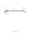
- FIG. 5 is a cross-sectional view of the electrical assembly of FIG. 1
- FIG. 5(A) is another cross-sectional view of the electrical assembly of FIG. 1 to show the electronic package is retained between the latch and the stopper/kicker;
- FIG. 6 is an exploded perspective view of the electrical assembly of FIG. 4 and printed circuit board assembly to which the electrical assembly is assembled;
- FIG. 7 is an assembled perspective view of the electrical assembly which is assembled upon the printed circuit board assembly of FIG. 6 .
- an electrical assembly 100 includes a clip 1 and an electronic package 2 retained by the clip 1 .
- the electrical assembly 100 is adapted to be mounted upon the printed circuit board assembly 200 for connecting the electronic package 2 to the printed circuit boar 4 .
- the clip 1 includes a frame structure 10 with a receiving cavity 11 therein for receiving the electronic package 2 .
- the frame structure 10 includes a pair of short bars 101 extending along a transverse direction, and a pair of long bars 102 extending along a front-to-back direction and linked with the pair of short bars 101 .
- the long bars 101 have the positioning blocks 15 for engaging the housing 3 of the electrical connector (illustrated later).
- One of the short bars 101 includes a stopper/kicker 12 and a presser 13 interlinked with each other in a lever manner along a direction perpendicular to the short bar 101 .
- the stopper/kicker 12 functions to not only support/retain the electronic package 2 in use but also eject out the electronic package 2 from the clip 1 when necessary.
- the presser 13 extends in direction away from the receiving cavity 11 , and includes a pressing head 130 .
- the short bar 101 forms a groove 14 for not only allowing deflection of the presser 13 but also enhancing flexibility/deformation of around the stopper/kicker 12 . Therefore, when the presser 13 is downwardly deflected, the stopper/kicker 12 is upwardly deflected correspondingly.
- a latch 16 is formed on the short bar 101 and includes a hook 161 extending toward the receiving cavity 11 , and a rib 162 .
- the hook 161 cooperates with the stopper/kicker 12 to sandwich the electronic package 2 therebetween in the vertical direction.
- on each short bar 101 there is one latch 16 and a pair of stopper/kicker 12 by two sides of the latch 16 forming three points retention to commonly retain the electronic package 2 in position.
- Four through holes 17 are formed around four corners of the clip 1 and equipped with locks 18 for securing to the heat sink assembly (not shown).
- the electronic package 2 is adapted to be received within the receiving cavity 11 and includes a substrate 21 and a chip 22 thereon.
- the substrate 21 forms pair of notches 210 to receive the corresponding ribs 162 during assembling.
- the presser 13 is downwardly moved to actuate the stopper/kicker 12 to upwardly move, eject and disengage the electronic package 2 from the clip 1 .
- the transverse end 141 of the groove 14 may further extend to a area behind the latch 16 to make the latch more soft so as to be moved in response to the downward movement of the presser 13 due to a twisting effect occurring thereabouts.
- the printed circuit board assembly 200 includes an insulative housing 3 , the printed circuit board 4 , and the metallic frame 5 .
- the metallic frame 5 is mounted upon the printed circuit board 4 and surrounds the housing 3 .
- the electronic package 2 is firstly assembled within the clip 1 as the electrical assembly 100 .
- the electrical assembly 100 is mounted to a bottom face of the heat sink assembly (not shown) via the locks 18 .
- the electrical assembly 100 with the associated heat sink assembly (not shown) is assembled to printed circuit board assembly 200 wherein the positioning blocks 15 are engaged between the housing 3 and the metallic frame 5 , and the positioning posts 51 extend through the corresponding through holes 17 and into the heat sink assembly (not shown).
- the metallic frame 5 forms a space 50 above the printed circuit board 4 corresponding to the presser 13 in the vertical direction for avoiding any interference between the presser 13 and the metallic frame 5 .
Landscapes
- Engineering & Computer Science (AREA)
- Microelectronics & Electronic Packaging (AREA)
- Physics & Mathematics (AREA)
- Condensed Matter Physics & Semiconductors (AREA)
- General Physics & Mathematics (AREA)
- Computer Hardware Design (AREA)
- Power Engineering (AREA)
- Mounting Of Printed Circuit Boards And The Like (AREA)
- Cooling Or The Like Of Semiconductors Or Solid State Devices (AREA)
- Supply And Installment Of Electrical Components (AREA)
- Container, Conveyance, Adherence, Positioning, Of Wafer (AREA)
Abstract
Description
Claims (20)
Applications Claiming Priority (3)
| Application Number | Priority Date | Filing Date | Title |
|---|---|---|---|
| CN201621470152U | 2016-12-29 | ||
| CN201621470152.9U CN206401563U (en) | 2016-12-29 | 2016-12-29 | Clamping device and its component |
| CN201621470152.9 | 2016-12-29 |
Publications (2)
| Publication Number | Publication Date |
|---|---|
| US20180190561A1 US20180190561A1 (en) | 2018-07-05 |
| US10276473B2 true US10276473B2 (en) | 2019-04-30 |
Family
ID=59517538
Family Applications (1)
| Application Number | Title | Priority Date | Filing Date |
|---|---|---|---|
| US15/856,102 Active US10276473B2 (en) | 2016-12-29 | 2017-12-28 | Easily detachable CPU clip |
Country Status (3)
| Country | Link |
|---|---|
| US (1) | US10276473B2 (en) |
| CN (1) | CN206401563U (en) |
| TW (1) | TWM568523U (en) |
Cited By (1)
| Publication number | Priority date | Publication date | Assignee | Title |
|---|---|---|---|---|
| US11109502B2 (en) | 2019-04-12 | 2021-08-31 | Fuding Precision Components (Shenzhen) Co., Ltd. | Connector assembly with retainer for CPU |
Families Citing this family (6)
| Publication number | Priority date | Publication date | Assignee | Title |
|---|---|---|---|---|
| CN106848717B (en) * | 2016-12-20 | 2020-06-30 | 富士康(昆山)电脑接插件有限公司 | Electrical connector assembly |
| CN206401563U (en) * | 2016-12-29 | 2017-08-11 | 富士康(昆山)电脑接插件有限公司 | Clamping device and its component |
| CN207781966U (en) | 2018-01-15 | 2018-08-28 | 富士康(昆山)电脑接插件有限公司 | Electric coupler component and its clamping piece |
| WO2020097823A1 (en) * | 2018-11-14 | 2020-05-22 | 惠州市吉瑞科技有限公司深圳分公司 | Smoking device which heats inhalable material |
| TWM606322U (en) * | 2019-04-12 | 2021-01-11 | 英屬開曼群島商鴻騰精密科技股份有限公司 | Cpu socket assembly and bolster assembly thereof |
| CN116706600B (en) * | 2023-07-27 | 2024-01-09 | 温州贵派电器有限公司 | A waterproof French socket |
Citations (25)
| Publication number | Priority date | Publication date | Assignee | Title |
|---|---|---|---|---|
| US4810200A (en) * | 1987-05-18 | 1989-03-07 | E. I. Du Pont De Nemours And Company | IC-pack connector apparatus having ejecting function |
| US5073116A (en) * | 1991-03-01 | 1991-12-17 | Amp Incorporated | Surface mount LCC socket |
| US5380213A (en) * | 1993-05-21 | 1995-01-10 | Burndy Corporation | Electrical connector with improved ejectors and assembly |
| US5389000A (en) * | 1993-11-18 | 1995-02-14 | Molex Incorporated | Edge card connector with improved latch/eject mechanism |
| US5571025A (en) * | 1993-12-16 | 1996-11-05 | Hirose Electric Co., Ltd. | Circuit board electrical connector |
| US5573427A (en) * | 1993-01-22 | 1996-11-12 | Yamaichi Electronics Co., Ltd. | IC carrier |
| US5660552A (en) * | 1994-04-18 | 1997-08-26 | Japan Aviation Electronics Industry, Limited | Socket connector with a push-button for a bell crank |
| US5662485A (en) * | 1996-01-19 | 1997-09-02 | Framatome Connectors Usa Inc. | Printed circuit board connector with locking ejector |
| US5672072A (en) * | 1993-12-16 | 1997-09-30 | Hirose Electric Co., Ltd. | Circuit board electrical connector |
| US6340306B1 (en) * | 1998-12-21 | 2002-01-22 | Avaya Technology Corp. | Bridge clip for a connector |
| US6503093B1 (en) * | 1996-07-31 | 2003-01-07 | Hirose Electric Co., Ltd. | Circuit board electrical connector |
| US6651817B2 (en) * | 2000-10-18 | 2003-11-25 | Techwing Co., Ltd. | Test tray insert of test handler |
| US6802728B1 (en) * | 2003-08-14 | 2004-10-12 | Hon Hai Precision Ind. Co., Ltd. | Socket connector having ejecting mechanism |
| US7500867B1 (en) * | 2008-05-08 | 2009-03-10 | Dell Products, Lp | Cable clip that snaps onto connector housing |
| US20100167572A1 (en) * | 2008-12-26 | 2010-07-01 | Hon Hai Precision Ind. Co., Ltd. | Electrical connector assembly having clip-fastening mechanism |
| US7815456B2 (en) * | 2008-12-22 | 2010-10-19 | Yamaichi Electronics Co., Ltd. | Semiconductor device socket |
| US7871275B1 (en) * | 2009-12-04 | 2011-01-18 | Tyco Electronics Corporation | Interposer frame assembly for mating a circuit board with an interposer assembly |
| US20140162475A1 (en) * | 2012-12-11 | 2014-06-12 | Gaurav Chawla | Connector assembly and method |
| US8787035B2 (en) * | 2011-04-05 | 2014-07-22 | Tyco Electronics Corporation | Electrical interconnect device |
| US20140328037A1 (en) * | 2013-05-02 | 2014-11-06 | Hon Hai Precision Industry Co., Ltd. | Carrier and carrier assembly used thereof for positioning ic package |
| CN204315804U (en) | 2014-12-19 | 2015-05-06 | 番禺得意精密电子工业有限公司 | Electric connector |
| US9231318B2 (en) * | 2012-03-30 | 2016-01-05 | Intel Corporation | Integrated package insertion and loading mechanism (iPILM) |
| US20160261068A1 (en) * | 2015-03-05 | 2016-09-08 | Molex, Llc | Card holding member and card connector |
| US20180159253A1 (en) * | 2016-12-01 | 2018-06-07 | Foxconn Interconnect Technology Limited | Cpu retainer mounted upon pcb |
| US20180190561A1 (en) * | 2016-12-29 | 2018-07-05 | Foxconn Interconnect Technology Limited | Easily detachable cpu clip |
-
2016
- 2016-12-29 CN CN201621470152.9U patent/CN206401563U/en active Active
-
2017
- 2017-12-26 TW TW106219175U patent/TWM568523U/en not_active IP Right Cessation
- 2017-12-28 US US15/856,102 patent/US10276473B2/en active Active
Patent Citations (26)
| Publication number | Priority date | Publication date | Assignee | Title |
|---|---|---|---|---|
| US4810200A (en) * | 1987-05-18 | 1989-03-07 | E. I. Du Pont De Nemours And Company | IC-pack connector apparatus having ejecting function |
| US5073116A (en) * | 1991-03-01 | 1991-12-17 | Amp Incorporated | Surface mount LCC socket |
| US5573427A (en) * | 1993-01-22 | 1996-11-12 | Yamaichi Electronics Co., Ltd. | IC carrier |
| US5380213A (en) * | 1993-05-21 | 1995-01-10 | Burndy Corporation | Electrical connector with improved ejectors and assembly |
| US5389000A (en) * | 1993-11-18 | 1995-02-14 | Molex Incorporated | Edge card connector with improved latch/eject mechanism |
| US5571025A (en) * | 1993-12-16 | 1996-11-05 | Hirose Electric Co., Ltd. | Circuit board electrical connector |
| US5672072A (en) * | 1993-12-16 | 1997-09-30 | Hirose Electric Co., Ltd. | Circuit board electrical connector |
| US5660552A (en) * | 1994-04-18 | 1997-08-26 | Japan Aviation Electronics Industry, Limited | Socket connector with a push-button for a bell crank |
| US5662485A (en) * | 1996-01-19 | 1997-09-02 | Framatome Connectors Usa Inc. | Printed circuit board connector with locking ejector |
| US6503093B1 (en) * | 1996-07-31 | 2003-01-07 | Hirose Electric Co., Ltd. | Circuit board electrical connector |
| US6340306B1 (en) * | 1998-12-21 | 2002-01-22 | Avaya Technology Corp. | Bridge clip for a connector |
| US6651817B2 (en) * | 2000-10-18 | 2003-11-25 | Techwing Co., Ltd. | Test tray insert of test handler |
| US6802728B1 (en) * | 2003-08-14 | 2004-10-12 | Hon Hai Precision Ind. Co., Ltd. | Socket connector having ejecting mechanism |
| US7500867B1 (en) * | 2008-05-08 | 2009-03-10 | Dell Products, Lp | Cable clip that snaps onto connector housing |
| US7815456B2 (en) * | 2008-12-22 | 2010-10-19 | Yamaichi Electronics Co., Ltd. | Semiconductor device socket |
| US20100167572A1 (en) * | 2008-12-26 | 2010-07-01 | Hon Hai Precision Ind. Co., Ltd. | Electrical connector assembly having clip-fastening mechanism |
| US7871275B1 (en) * | 2009-12-04 | 2011-01-18 | Tyco Electronics Corporation | Interposer frame assembly for mating a circuit board with an interposer assembly |
| US8787035B2 (en) * | 2011-04-05 | 2014-07-22 | Tyco Electronics Corporation | Electrical interconnect device |
| US9231318B2 (en) * | 2012-03-30 | 2016-01-05 | Intel Corporation | Integrated package insertion and loading mechanism (iPILM) |
| US9385457B2 (en) | 2012-12-11 | 2016-07-05 | Intel Corporation | Connector assembly and method |
| US20140162475A1 (en) * | 2012-12-11 | 2014-06-12 | Gaurav Chawla | Connector assembly and method |
| US20140328037A1 (en) * | 2013-05-02 | 2014-11-06 | Hon Hai Precision Industry Co., Ltd. | Carrier and carrier assembly used thereof for positioning ic package |
| CN204315804U (en) | 2014-12-19 | 2015-05-06 | 番禺得意精密电子工业有限公司 | Electric connector |
| US20160261068A1 (en) * | 2015-03-05 | 2016-09-08 | Molex, Llc | Card holding member and card connector |
| US20180159253A1 (en) * | 2016-12-01 | 2018-06-07 | Foxconn Interconnect Technology Limited | Cpu retainer mounted upon pcb |
| US20180190561A1 (en) * | 2016-12-29 | 2018-07-05 | Foxconn Interconnect Technology Limited | Easily detachable cpu clip |
Cited By (1)
| Publication number | Priority date | Publication date | Assignee | Title |
|---|---|---|---|---|
| US11109502B2 (en) | 2019-04-12 | 2021-08-31 | Fuding Precision Components (Shenzhen) Co., Ltd. | Connector assembly with retainer for CPU |
Also Published As
| Publication number | Publication date |
|---|---|
| TWM568523U (en) | 2018-10-11 |
| CN206401563U (en) | 2017-08-11 |
| US20180190561A1 (en) | 2018-07-05 |
Similar Documents
| Publication | Publication Date | Title |
|---|---|---|
| US10276473B2 (en) | Easily detachable CPU clip | |
| US9755348B2 (en) | Waterproof electrical connector assembly | |
| US20200203886A1 (en) | Plug connector assembly | |
| US7140890B1 (en) | Electrical connector assembly capable of being moved by vacuum-suction device | |
| US9730351B2 (en) | Electrical connector assembly with holding member | |
| US8328567B1 (en) | Card edge connector and assembly including the same | |
| US10361505B2 (en) | Dual-cover structure protectively enclosing socket | |
| US20130130526A1 (en) | Card edge connector | |
| US20110104926A1 (en) | Electrical connector with an improved board lock | |
| US10720730B2 (en) | Card edge connector having metallic member formed integrally with insulative housing | |
| US10651106B2 (en) | Electrical connector equipped with clip | |
| US9385453B2 (en) | Card edge connector with an improved ejector | |
| US20150364888A1 (en) | Method for manufacturing electrical connector with multiple inject-molding processes | |
| US9893458B2 (en) | Dust-proof cover and electrical connector assembly using the same | |
| US20170110816A1 (en) | Clip and electrical connector assembly | |
| US10038277B2 (en) | Card edge connector with metal latch | |
| US9004934B2 (en) | Card edge connector | |
| US20160072208A1 (en) | Electrical connector | |
| US20150207269A1 (en) | Card connector with metallic retaining plate | |
| US20190088572A1 (en) | Heast sink fastening seat for use with electrical connector | |
| US9954321B2 (en) | Card edge connector | |
| US9627834B2 (en) | Electrical connector with improved fixing structure | |
| US9223100B2 (en) | Retention module for positioning conversion module | |
| JP2018097957A (en) | Housing of connector for substrate, connector for substrate and connector for substrate with case | |
| US10553981B2 (en) | Electrical connector with fastening nut supportably held by metallic shell |
Legal Events
| Date | Code | Title | Description |
|---|---|---|---|
| AS | Assignment |
Owner name: FOXCONN INTERCONNECT TECHNOLOGY LIMITED, CAYMAN IS Free format text: ASSIGNMENT OF ASSIGNORS INTEREST;ASSIGNORS:WU, HENG-KANG;PENG, FU-JIN;REEL/FRAME:044495/0193 Effective date: 20171225 |
|
| FEPP | Fee payment procedure |
Free format text: ENTITY STATUS SET TO UNDISCOUNTED (ORIGINAL EVENT CODE: BIG.); ENTITY STATUS OF PATENT OWNER: LARGE ENTITY |
|
| STPP | Information on status: patent application and granting procedure in general |
Free format text: PUBLICATIONS -- ISSUE FEE PAYMENT VERIFIED |
|
| STCF | Information on status: patent grant |
Free format text: PATENTED CASE |
|
| MAFP | Maintenance fee payment |
Free format text: PAYMENT OF MAINTENANCE FEE, 4TH YEAR, LARGE ENTITY (ORIGINAL EVENT CODE: M1551); ENTITY STATUS OF PATENT OWNER: LARGE ENTITY Year of fee payment: 4 |