US10251303B2 - Server display for displaying server component information - Google Patents
Server display for displaying server component information Download PDFInfo
- Publication number
- US10251303B2 US10251303B2 US15/587,893 US201715587893A US10251303B2 US 10251303 B2 US10251303 B2 US 10251303B2 US 201715587893 A US201715587893 A US 201715587893A US 10251303 B2 US10251303 B2 US 10251303B2
- Authority
- US
- United States
- Prior art keywords
- display
- server
- slot
- slots
- information
- Prior art date
- Legal status (The legal status is an assumption and is not a legal conclusion. Google has not performed a legal analysis and makes no representation as to the accuracy of the status listed.)
- Active
Links
Images


Classifications
-
- H—ELECTRICITY
- H05—ELECTRIC TECHNIQUES NOT OTHERWISE PROVIDED FOR
- H05K—PRINTED CIRCUITS; CASINGS OR CONSTRUCTIONAL DETAILS OF ELECTRIC APPARATUS; MANUFACTURE OF ASSEMBLAGES OF ELECTRICAL COMPONENTS
- H05K7/00—Constructional details common to different types of electric apparatus
- H05K7/14—Mounting supporting structure in casing or on frame or rack
- H05K7/1485—Servers; Data center rooms, e.g. 19-inch computer racks
- H05K7/1488—Cabinets therefor, e.g. chassis or racks or mechanical interfaces between blades and support structures
- H05K7/1494—Cabinets therefor, e.g. chassis or racks or mechanical interfaces between blades and support structures having hardware for monitoring blades, e.g. keyboards, displays
-
- G—PHYSICS
- G06—COMPUTING; CALCULATING OR COUNTING
- G06F—ELECTRIC DIGITAL DATA PROCESSING
- G06F1/00—Details not covered by groups G06F3/00 - G06F13/00 and G06F21/00
- G06F1/16—Constructional details or arrangements
- G06F1/18—Packaging or power distribution
- G06F1/183—Internal mounting support structures, e.g. for printed circuit boards, internal connecting means
- G06F1/186—Securing of expansion boards in correspondence to slots provided at the computer enclosure
-
- G—PHYSICS
- G06—COMPUTING; CALCULATING OR COUNTING
- G06F—ELECTRIC DIGITAL DATA PROCESSING
- G06F11/00—Error detection; Error correction; Monitoring
- G06F11/30—Monitoring
- G06F11/3003—Monitoring arrangements specially adapted to the computing system or computing system component being monitored
- G06F11/3044—Monitoring arrangements specially adapted to the computing system or computing system component being monitored where the computing system component is the mechanical casing of the computing system
-
- G—PHYSICS
- G06—COMPUTING; CALCULATING OR COUNTING
- G06F—ELECTRIC DIGITAL DATA PROCESSING
- G06F11/00—Error detection; Error correction; Monitoring
- G06F11/30—Monitoring
- G06F11/3051—Monitoring arrangements for monitoring the configuration of the computing system or of the computing system component, e.g. monitoring the presence of processing resources, peripherals, I/O links, software programs
-
- G—PHYSICS
- G06—COMPUTING; CALCULATING OR COUNTING
- G06F—ELECTRIC DIGITAL DATA PROCESSING
- G06F11/00—Error detection; Error correction; Monitoring
- G06F11/30—Monitoring
- G06F11/32—Monitoring with visual or acoustical indication of the functioning of the machine
- G06F11/324—Display of status information
-
- H—ELECTRICITY
- H05—ELECTRIC TECHNIQUES NOT OTHERWISE PROVIDED FOR
- H05K—PRINTED CIRCUITS; CASINGS OR CONSTRUCTIONAL DETAILS OF ELECTRIC APPARATUS; MANUFACTURE OF ASSEMBLAGES OF ELECTRICAL COMPONENTS
- H05K7/00—Constructional details common to different types of electric apparatus
- H05K7/14—Mounting supporting structure in casing or on frame or rack
- H05K7/1485—Servers; Data center rooms, e.g. 19-inch computer racks
- H05K7/1498—Resource management, Optimisation arrangements, e.g. configuration, identification, tracking, physical location
Definitions
- This disclosure generally relates to information handling systems, and more particularly relates to servers and determining a status of a server slot and a device.
- An information handling system generally processes, compiles, stores, and/or communicates information or data for business, personal, or other purposes. Because technology and information handling needs and requirements may vary between different applications, information handling systems may also vary regarding what information is handled, how the information is handled, how much information is processed, stored, or communicated, and how quickly and efficiently the information may be processed, stored, or communicated. The variations in information handling systems allow for information handling systems to be general or configured for a specific user or specific use such as financial transaction processing, reservations, enterprise data storage, or global communications. In addition, information handling systems may include a variety of hardware and software resources that may be configured to process, store, and communicate information and may include one or more computer systems, data storage systems, and networking systems.
- An example of an information handling system may be a server with slots for peripheral devices.
- a server may include a set of slots for adding peripheral devices, and a server chassis having a set of openings corresponding to the set of slots.
- a display mounted on the server chassis proximate the opening displays slot characteristics, slot status information, or user defined information corresponding to the slots.
- FIG. 1 is a block diagram illustrating a generalized information handling system according to an embodiment of the present disclosure
- FIG. 2 illustrates a top view of a server according to an embodiment of the present disclosure
- FIGS. 3 a and 3 b illustrate an isometric top-side angled view of a server according to an embodiment of the present disclosure
- FIGS. 4 a and 4 b illustrate an isometric top-side angled view of a server portion according to an embodiment of the present disclosure
- FIG. 5 illustrates a back view of a server according to an embodiment of the present disclosure
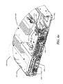
- FIG. 6 illustrates a top isometric view of a server portion and display according to an embodiment of the present disclosure
- FIG. 7 illustrates a back view of a server according to an embodiment of the present disclosure
- FIGS. 8 a and 8 b illustrate a back view of a server according to an embodiment of the present disclosure.
- FIG. 9 illustrates a back view of a server according to an embodiment of the present disclosure.
- FIG. 1 illustrates a generalized embodiment of information handling system 100 .
- information handling system 100 can include any instrumentality or aggregate of instrumentalities operable to compute, classify, process, transmit, receive, retrieve, originate, switch, store, display, manifest, detect, record, reproduce, handle, or utilize any form of information, intelligence, or data for business, scientific, control, entertainment, or other purposes.
- information handling system 100 can be a processor system which may be a System-on-a-Chip (SoC), a personal computer, a laptop computer, a smart phone, a tablet device or other consumer electronic device, storage array, a network server, a network storage device, a switch router or other network communication device, or any other suitable device and may vary in size, shape, performance, functionality, and price.
- information handling system 100 can include processing resources for executing machine-executable code, such as a central processing unit (CPU), a programmable logic array (PLA), an embedded device such as a SoC, or other control logic hardware.
- Information handling system 100 can also include one or more computer-readable medium for storing machine-executable code, such as software or data.
- Additional components of information handling system 100 can include one or more storage devices that can store machine-executable code, one or more communications ports for communicating with external devices, and various input and output (I/O) devices, such as a keyboard, a mouse, and a video display.
- Information handling system 100 can also include one or more buses operable to transmit information between the various hardware components.
- Information handling system 100 can include devices or modules that embody one or more of the devices or modules described above, and operates to perform one or more of the methods described above.
- Information handling system 100 includes a processors 102 and 104 , a chipset 110 , a memory 120 , a graphics interface 130 , include a basic input and output system/extensible firmware interface (BIOS/EFI) module 140 , a disk controller 150 , a disk emulator 160 , an input/output (I/O) interface 170 , and a network interface 180 .
- BIOS/EFI basic input and output system/extensible firmware interface
- Processor 102 is connected to chipset 110 via processor interface 106
- processor 104 is connected to the chipset via processor interface 108 .
- Memory 120 is connected to chipset 110 via a memory bus 122 .
- Graphics interface 130 is connected to chipset 110 via a graphics interface 132 , and provides a video display output 136 to a video display 134 .
- information handling system 100 includes separate memories that are dedicated to each of processors 102 and 104 via separate memory interfaces.
- An example of memory 120 includes random access memory (RAM) such as static RAM (SRAM), dynamic RAM (DRAM), non-volatile RAM (NV-RAM), or the like, read only memory (ROM), another type of memory, or a combination thereof.
- RAM random access memory
- SRAM static RAM
- DRAM dynamic RAM
- NV-RAM non-volatile RAM
- ROM read only memory
- BIOS/EFI module 140 , disk controller 150 , and I/O interface 170 are connected to chipset 110 via an I/O channel 112 .
- I/O channel 112 includes a Peripheral Component Interconnect (PCI) interface, a PCI-Extended (PCI-X) interface, a high speed PCI-Express (PCIe) interface, another industry standard or proprietary communication interface, or a combination thereof.
- Chipset 110 can also include one or more other I/O interfaces, including an Industry Standard Architecture (ISA) interface, a Small Computer Serial Interface (SCSI) interface, an Inter-Integrated Circuit (I 2 C) interface, a System Packet Interface (SPI), a Universal Serial Bus (USB), another interface, or a combination thereof.
- ISA Industry Standard Architecture
- SCSI Small Computer Serial Interface
- I 2 C Inter-Integrated Circuit
- SPI System Packet Interface
- USB Universal Serial Bus
- BIOS/EFI module 140 includes BIOS/EFI code operable to detect resources within information handling system 100 , to provide drivers for the resources, initialize the resources, and access the resources. BIOS/EFI module 140 includes code that operates to detect resources within information handling system 100 , to provide drivers for the resources, to initialize the resources, and to access the resources.
- Disk controller 150 includes a disk interface 152 that connects the disc controller to a hard disk drive (HDD) 154 , to an optical disk drive (ODD) 156 , and to disk emulator 160 .
- disk interface 152 includes an Integrated Drive Electronics (IDE) interface, an Advanced Technology Attachment (ATA) such as a parallel ATA (PATA) interface or a serial ATA (SATA) interface, a SCSI interface, a USB interface, a proprietary interface, or a combination thereof.
- Disk emulator 160 permits a solid-state drive 164 to be connected to information handling system 100 via an external interface 162 .
- An example of external interface 162 includes a USB interface, an IEEE 1394 (Firewire) interface, a proprietary interface, or a combination thereof.
- solid-state drive 164 can be disposed within information handling system 100 .
- I/O interface 170 includes a peripheral interface 172 that connects the I/O interface to an add-on resource 174 , to a TPM 176 , and to network interface 180 .
- Peripheral interface 172 can be the same type of interface as I/O channel 112 , or can be a different type of interface. As such, I/O interface 170 extends the capacity of I/O channel 112 when peripheral interface 172 and the I/O channel are of the same type, and the I/O interface translates information from a format suitable to the I/O channel to a format suitable to the peripheral channel 172 when they are of a different type.
- Add-on resource 174 can include a data storage system, an additional graphics interface, a network interface card (NIC), a sound/video processing card, another add-on resource, or a combination thereof.
- Add-on resource 174 can be on a main circuit board, on separate circuit board or add-in card disposed within information handling system 100 , a device that is external to the information handling system, or a combination thereof.
- Network interface 180 represents a NIC disposed within information handling system 100 , on a main circuit board of the information handling system, integrated onto another component such as chipset 110 , in another suitable location, or a combination thereof.
- Network interface device 180 includes network channels 182 and 184 that provide interfaces to devices that are external to information handling system 100 .
- network channels 182 and 184 are of a different type than peripheral channel 172 and network interface 180 translates information from a format suitable to the peripheral channel to a format suitable to external devices.
- An example of network channels 182 and 184 includes InfiniBand channels, Fibre Channel channels, Gigabit Ethernet channels, proprietary channel architectures, or a combination thereof.
- Network channels 182 and 184 can be connected to external network resources (not illustrated).
- the network resource can include another information handling system, a data storage system, another network, a grid management system, another suitable resource, or a combination thereof.
- a server may have a server chassis defining a physical shape and outline of the server.
- the server may include a motherboard interior to the server chassis, the motherboard supporting a baseboard management controller (BMC) of the server.
- BMC baseboard management controller
- a BMC may be considered a specialized service processor that monitors the physical state of a server or other hardware devices.
- the BMC of the server may interface with, for example, monitor, control or configure components of the server.
- a server may exhibit modularity and one or more components may be added to the server, and these components may be monitored by the BMC.
- a server may have one or more connections or sets of connections for adding one or more components such as modular peripheral devices to the server.
- peripheral devices may include Input/Output (IO) devices which may be used by the server to connect to and communicate with a network or may includes memory devices, such as solid state devices (SSDs), for example.
- IO Input/Output
- the server chassis may have one or more openings to allow for access to these peripheral devices when the peripheral devices are added to the server.
- a connection or set of connections may be a physical slot connection, for example, a peripheral card connector, into which a portion of a peripheral device is inserted to add the peripheral device to the server as a server component.
- a peripheral card connector may provide mechanical support to a peripheral device inserted into the peripheral card connector to maintain the peripheral device in a position, for example in a vertical or horizontal position.
- a server and server chassis may be considered to have a set of slots, each slot of the set of slots having a peripheral card connector to add a peripheral device to the server.
- a slot is a physical space in a server into which a peripheral device may be added, or slotted, into the server, for example by sliding a connection portion of the peripheral device into the peripheral card connector of the slot.
- a slot may have a corresponding opening in the server chassis to allow for access to the peripheral device inhabiting the slot.
- a slot may be a universal slot and the peripheral card connector may have a common connection footprint, and the added peripheral device may be added to the server as a server component and interface with server via the universal slot and connection thereto.
- a universal slot may have a common physical footprint and provide a common set of connections with card connectors of the same specification.
- a server may have multiple universal slots to allow flexibility to add different peripherals as server components.
- the slots may generally be located in a portion of the server near the walls of the server chassis, and the server chassis have an opening in the vicinity of the slots such that peripherals coupled to the slots may be at least visually accessible by a viewer of the server.
- Individual slots may have different characteristics despite the universal connection footprint, for example, different communication protocols and versions of the communication protocols may be supported by the individual slot.
- a universal slot may have a standard or universal, that is common, physical footprint, and common connector
- the server may interface with the peripheral device inserted into the slot according to different communication protocols, different versions of communication protocols, or different speeds of communication of communication protocols over the common connector.
- the bus structure and hardware of an individual server and individual peripheral may support varying higher (or lower) communication speeds between the individual server and individual peripheral, and the server and peripheral may communicate according to those higher communication speeds as allowed by the communication protocol.
- device performance may degrade over time, or it may be desirable to have communications between peripheral and server use an older version or different standard and these setting may be made to peripheral and server, while the physical footprint and the physical connector of the universal slot will remain the same.
- slots are positioned towards the rear, or located in the rear portion of the server.
- these peripherals may add IO capability to the server and so may include one or more ports for network connections which may be accessed through the server chassis openings.
- the display may be located proximate a server chassis opening corresponding to a universal slot and indicate information relating to that slot, such as slot characteristics, characteristics of the peripheral in the slot, characteristics of communication between peripheral and server or network, or other characteristics.
- the display may be directly mounted on the server chassis, by for example, a housing mounted on the server, and the display may be connected to the BMC of the server and controlled and configured by the BMC.
- the display may include a set of light emitting diodes (LEDs), may be an LCD display, or an Electronic-ink display, or other display type or combination of display types.
- LEDs light emitting diodes
- the display may be a semi-permanent type of display which maintains display information on the display even when the display is unpowered, or receiving minimal power from a quiescent server.
- FIG. 2 shows a top view of a server 200 .
- Server 200 includes server chassis 201 defining the physical footprint and dimensions of server 200 .
- the portion of server chassis indicated by 202 may be considered the front of server 200
- portion of server chassis indicated by 203 may be considered the back of server 200 .
- Server 200 includes motherboard 205 , BMC 207 , slots 212 and 214 , and riser 230 providing one or more horizontal expansion slots.
- slots 212 and 214 , and vertical riser 230 are positioned towards the back of server 200 and abut back 203 of server 200 .
- BMC 207 is mounted on motherboard 205 .
- Slot 212 includes peripheral card connector 222 and slot 214 includes peripheral card connector 224 .
- BMC 207 may be aware of the communication protocols supported by slots 212 and 214 .
- a display 242 is mounted on server chassis 201 proximate to slots 212 and 214 .
- Display 242 is mounted to back 203 of server 200 .
- Display 242 may be in communication with BMC 207 and controlled by BMC 207 to output information associated with slots 212 and 214 .
- a display 244 is mounted on server chassis 201 proximate riser 230 .
- Display 244 is mounted to back 203 of server 200 .
- FIGS. 3 a and 3 b show an isometric top-side angled view of server 300 .
- FIG. 3 a shows server 300 unpopulated with peripheral devices; that is slots of server 300 are unpopulated with peripheral devices.
- FIG. 3 b shows server 300 populated with peripheral devices; that is slots of server 300 are populated with peripheral devices.
- Server 300 includes server chassis portion 301 defining a physical space or footprint of server 300 .
- 305 indicates a back of server 300 and server chassis 301 .
- FIG. 3 a shows peripheral card connectors 322 and 324 of corresponding slots and corresponding display 350 directly mounted to server chassis 301 .
- the slots corresponding to peripheral card connectors 322 and 324 are unpopulated, and thus peripheral card connectors 322 and 324 are unconnected, as shown in FIG. 3 a.
- FIG. 3 b shown slots corresponding to peripheral card connectors 322 and 324 populated by peripheral devices 332 and 334 , respectively.
- peripheral card connector 322 is obscured by peripheral device 334
- peripheral device 334 is mechanically connected to peripheral device connector 324 .
- the slots corresponding to peripheral card connectors 322 and 324 are populated by peripheral devices.
- display 350 is relatively proximate the slots of server 300 and peripheral devices 332 and 334 populating the slots.
- a BMC of server 300 may monitor the communications between server 300 and peripheral devices 332 and 334 and may be aware of the communication protocol used and communication speeds between server 300 and peripheral devices 332 and 334 .
- FIGS. 4 a and 4 b show an isometric top-side angled view of server portion 400 .
- Server portion 400 is physically defined by server chassis portion 401 .
- FIG. 4 a shows server 400 portion unpopulated with peripheral devices; that is slots of server 400 portion are unpopulated with peripheral devices.
- FIG. 4 b shows server 400 portion populated with peripheral devices; that is slots of server 400 portion are populated with peripheral devices.
- 403 indicates a back of server portion 400 .
- Server 400 portion includes vertical riser 430 which may include auxiliary slots to hold one or more peripheral devices.
- FIG. 4 a shows unpopulated slots 412 and 414 with corresponding peripheral card connectors 422 and 424 .
- Display 442 is directly mounted to server chassis portion 401 by a display housing or mounting which may be considered to form part of server chassis portion 401 .
- display 442 is proximate to or in the immediate vicinity of slots 412 and 414 .
- Vertical riser 430 includes horizontal slots 432 and 434 .
- display 444 abuts slots 432 and 434 .
- Display 444 is directly mounted to server chassis portion 401 by a display housing or mounting which may be considered to form part of server chassis portion 401 .
- Display 444 displays information corresponding to slots 432 and 434 .
- FIG. 4 b shows slots 412 and 414 populated with peripheral devices 452 and 454 which obscure slots 412 and 414 in the view provided by FIG. 4 b .
- portions of peripheral devices 452 and 454 extend through server chassis portion 401 at 456 proximate display 442 such that display 442 abuts peripheral devices 452 and 454 at 456 at server back 403 .
- riser 430 is populated by peripheral devices which protrude through slots 432 and 434 at 458 such that display 444 abuts the peripheral devices.
- FIG. 5 shows a back view of server 500 .
- Server 500 is physically defined by server chassis 501 of server 500 .
- Displays 516 and 526 are mounted on server chassis 501 .
- Slots 512 and 514 are parallel slots and abutted by display 516 which displays information pertaining to slots 512 and 514 .
- Slots 522 and 524 are parallel slots and abutted by display 526 which displays information pertaining to slots 522 and 524 .
- FIG. 6 is a top isometric view of server portion 600 and illustrates coupling a display to a back of a server.
- Server portion 600 includes server chassis portion 601 onto which a display 610 is mounted.
- Display 610 is provided, for example housed, in display housing 612 .
- Display housing 612 is mechanically coupled to, for example mounted on, display mount 614 which is coupled to server chassis portion 601 , to directly mount display 610 on server chassis portion 601 .
- Display housing 612 and thus display 610 are coupled to display mount 614 by fasteners 618 .
- Electrical connector 616 electrically connects display 610 to a motherboard of server portion 600 , and via, the motherboard, to a BMC of server portion 600 .
- Electrical connector 616 may be a rigid connector with a flex.
- electrical connector 616 may be a component with a defined shape and the shape may be deformable to provide a flex connection solution, such as flexible PCB or a discrete wire cable with plugs on both ends.
- Display 610 has a display connector 611 to connect to electrical connector 616 .
- the motherboard will have a similar connector interface to 616 (not shown).
- FIG. 7 is a back view of server 700 .
- Server 700 includes display 710 mounted on the back of server 700 and a set of slots 720 (slots 1 - 3 ), shown on the back of server 700 in FIG. 7 .
- Each of slots 1 - 3 has a corresponding peripheral card connector supporting one or more communication protocols and varying communication speeds.
- a BMC of server 700 (not shown) is aware of these supported communication protocols and varying communication speeds.
- slots 1 - 3 are populated with peripheral devices, the peripheral device and server 700 communicate according to one of the supported communication protocols and communication speeds.
- the BMC is aware of the communication protocol and communication speed used to communicate between server 700 and a peripheral device populating a slot of slots 1 - 3 .
- the BMC of server 700 is connected to and controls display 710 to cause display 710 to output information on display 710 .
- display 710 abuts the set of slots 720 and thus each of slots 1 - 3 .
- a portion of display 710 is thus proximate each slot of slots 1 - 3 .
- Display 710 may be divided into display portions 711 - 713 .
- Display portion 711 abuts and is proximate slot 1 (slot 721 ).
- Display portion 712 abuts and is proximate slot 2 (slot 722 ).
- Display portion 713 abuts and is proximate slot 3 (slot 723 ).
- Display portion 711 displays information pertaining to slot 1 (slot 721 ) as controlled by the BMC of server 700 .
- Display portion 712 displays information pertaining to slot 2 (slot 722 ) as controlled by the BMC of server 700 .
- Display portion 713 displays information pertaining to slot 3 (slot 723 ) as controlled by the BMC of server 700 .
- Each of display portions 711 - 713 may display different types of information relating to corresponding slots 721 - 723 : slot characteristics, slot status or user defined information.
- a user may interface with the BMC to display different types of information on display 710 and individual display portions 711 - 713 .
- the BMC of server 700 may control display 710 to display slot characteristics of slot 1 in display portion 711 corresponding to slot 1 .
- Slot characteristics may include the communication protocols supported by the slot, the communication speeds supported by the slot, the type of slot, the type of card connector of the slot, or other slot characteristics.
- a communication protocol may be various Peripheral Component Interconnect Express (PCIe) variants, for example.
- PCIe Peripheral Component Interconnect Express
- the BMC of server 700 may control display 710 to display slot status information of slot 2 in display portion 712 corresponding to slot 2 .
- Slot 2 may be populated with a peripheral device and the peripheral device may be communicating with server 700 according to one or more protocols at one or more speeds or may be in negotiations with server 700 or undergoing initialization by server 700 .
- Slot characteristics may include the protocol used to communicate with the peripheral device, communication speed, the state of the peripheral device such as operable or in configuration, or other status information related to the peripheral device.
- the BMC of server 700 may control display 710 to display user defined information of slot 3 in display portion 713 corresponding to slot 3 .
- Slot 3 may be populated with a peripheral device such as a network card and as such may be in communication with particular networks or coupled to a particular switch fabric.
- a user may communicate with the BMC controlling display 710 to cause display portion 713 to display a particular network indication, network group, or connection type.
- slots may be universal slots and the peripheral card connector of the slots may have a common connection footprint. While a universal slot may have a standard or universal, that is common, physical footprint, and common connector, the configuration of the slots may vary, and protocols supported by the slots may vary. For example, a slot and corresponding connector may support a set of protocols, such as communication protocols, and may be configured for a protocol of the set of supported protocols. Thus because slots generally have a common physical footprint and connector, an associated display portion as disclosed above allows for identification of slot capabilities and configurations for individual slots.
- a slot and corresponding connector may support the server communicating with a peripheral device installed in the slot according to a set of communication protocols including protocols and speeds such as: PCI Generations 3 and 4, Enhanced Modes of PCI Gen 4 (with varying communication speeds), Cache Coherence Interconnect for Acclerators (CCIX), and various future interconnect protocols at varying communication speeds.
- Slots may also be associated with particular server components such as specific dies or processors.
- individual slots may have specific power or cooling considerations. Slot performance may also degrade over time, thus reducing communication speeds supported by the slot, for example.
- the display portion associated with an individual slot may be used to provide such information regarding the slot.
- FIGS. 8 a and 8 b show a back of a server 800 .
- Server 800 includes a set of slots 810 and a corresponding display 820 proximate and abutting slots 810 .
- Slots 810 include slots 811 (slot 1 ), 812 (slot 2 ) and 813 (slot 3 ).
- Display 820 includes display portions 821 , 822 and 823 corresponding to slots 811 - 813 , respectively. That is display portion 821 corresponds to slot 811 and display information related to slot 811 .
- display portion 822 corresponds to slot 812 and display information related to slot 812 , and display portion 823 corresponds to slot 813 and display information related to slot 813 .
- slot 811 is configured for PCIe generation 3 and supports a communication speed of 8 Gbps (as indicated in corresponding display portion 821 ) such that a peripheral device installed in slot 811 will communicate with the server per PCIe generation 3 at 8 Gbps.
- Slot 812 is configured for PCIe generation 4 and the peripheral card connector of slot 812 supports a higher communication speed of 16 Gbps (as indicated in corresponding display portion 822 ) such that a peripheral device installed in slot 812 will communicate with the server per PCIe generation 4 at up to 16 Gbps.
- Slot 813 is configured for PCIe generation 4 and support communication speeds up to 25G (as indicated in corresponding display portion 822 ).
- slot 811 is supported by and in communication with server central processing unit (CPU) 1 , and die 1 of CPU 1 , as indicated in corresponding display portion 821 .
- Slot 812 is supported by and in communication with server CPU 1 , and die 3 of CPU 1 , as indicated in corresponding display portion 822 .
- slot 813 is supported by and in communication with server CPU 2 , and die 4 of CPU 2 , as indicated in corresponding display portion 823 .
- FIG. 9 shows a back view of a server 900 .
- Server 900 includes slots 910 and 920 , and LED displays 911 and 921 .
- LED displays 911 and 921 comprise LEDs and may vary color or blink rate to indicate different protocols or speeds associated with slots.
- LED display 911 is associated with slot 910 and displays information regarding slot 910 by way of visual LED display of colors or blink rates.
- LED display 921 is associated with slot 920 and displays information regarding slot 920 by way of visual LED display of colors or blink rates.
- the display may also have the ability to remember and display slot information even when server does not have power applied via “liquid paper” or E-ink or other.
- the display may further display a display of optimal versus sub-optimal configuration feedback information.
- the display may further display of differing capabilities of an individual slot as a function of CPU SKU, Riser type, or other.
- the display may further display indications of elements installed or various display modes of the display.
Landscapes
- Engineering & Computer Science (AREA)
- Theoretical Computer Science (AREA)
- General Engineering & Computer Science (AREA)
- Physics & Mathematics (AREA)
- General Physics & Mathematics (AREA)
- Computer Hardware Design (AREA)
- Quality & Reliability (AREA)
- Computing Systems (AREA)
- Microelectronics & Electronic Packaging (AREA)
- Power Engineering (AREA)
- Human Computer Interaction (AREA)
- Mathematical Physics (AREA)
- Debugging And Monitoring (AREA)
- Computer And Data Communications (AREA)
Abstract
Description
Claims (20)
Priority Applications (1)
| Application Number | Priority Date | Filing Date | Title |
|---|---|---|---|
| US15/587,893 US10251303B2 (en) | 2017-05-05 | 2017-05-05 | Server display for displaying server component information |
Applications Claiming Priority (1)
| Application Number | Priority Date | Filing Date | Title |
|---|---|---|---|
| US15/587,893 US10251303B2 (en) | 2017-05-05 | 2017-05-05 | Server display for displaying server component information |
Publications (2)
| Publication Number | Publication Date |
|---|---|
| US20180324973A1 US20180324973A1 (en) | 2018-11-08 |
| US10251303B2 true US10251303B2 (en) | 2019-04-02 |
Family
ID=64015154
Family Applications (1)
| Application Number | Title | Priority Date | Filing Date |
|---|---|---|---|
| US15/587,893 Active US10251303B2 (en) | 2017-05-05 | 2017-05-05 | Server display for displaying server component information |
Country Status (1)
| Country | Link |
|---|---|
| US (1) | US10251303B2 (en) |
Cited By (4)
| Publication number | Priority date | Publication date | Assignee | Title |
|---|---|---|---|---|
| US11347986B1 (en) * | 2021-07-23 | 2022-05-31 | Dell Products L.P. | Dynamic branding via a dynamic information tag |
| US20220308793A1 (en) * | 2021-03-25 | 2022-09-29 | Acer Incorporated | Method for writing data in parallel and data storage system |
| US11593057B2 (en) | 2021-07-23 | 2023-02-28 | Dell Products L.P. | Dynamic branding via a dynamic information tag |
| US11886249B2 (en) | 2021-07-23 | 2024-01-30 | Dell Products L.P. | Dynamic information tag |
Families Citing this family (2)
| Publication number | Priority date | Publication date | Assignee | Title |
|---|---|---|---|---|
| US11695229B1 (en) * | 2021-02-19 | 2023-07-04 | Xilinx, Inc. | Auxiliary power connector PCB |
| CN112965649A (en) * | 2021-02-24 | 2021-06-15 | 浪潮电子信息产业股份有限公司 | Server and IP information near-end visual control system of BMC module thereof |
Citations (16)
| Publication number | Priority date | Publication date | Assignee | Title |
|---|---|---|---|---|
| US5483229A (en) * | 1993-02-18 | 1996-01-09 | Yokogawa Electric Corporation | Input-output unit |
| US5601349A (en) * | 1995-07-25 | 1997-02-11 | Dell U.S.A., Lp | Captive latch mechanism for use with an expansion card cage in a personal computer |
| US5754112A (en) * | 1995-09-28 | 1998-05-19 | Sun Microsystems, Inc. | Power on, mated, and activity indicator for electronic devices including storage devices |
| US5790374A (en) * | 1996-12-06 | 1998-08-04 | Ncr Corporation | Method and apparatus for providing power activity and fault light support using light conduits for single connector architecture (SCA) disk drives |
| US5822196A (en) * | 1996-06-05 | 1998-10-13 | Compaq Computer Corporation | Securing a card in an electronic device |
| US20030018843A1 (en) * | 2001-07-17 | 2003-01-23 | Cooper Brently L. | Integrated expansion card slot status indicator and power actuator |
| US6747874B2 (en) * | 2002-11-12 | 2004-06-08 | Dell Products L.P. | Rack system with rear status indicator and method of use |
| US6867701B2 (en) * | 2002-04-18 | 2005-03-15 | International Business Machines Corporation | Computer-server rack enclosure fault light diagnostic system |
| US7129851B1 (en) * | 2003-09-29 | 2006-10-31 | Sun Microsystems, Inc. | Indicator feedback mechanism |
| US7259683B2 (en) * | 2002-11-26 | 2007-08-21 | Nec Corporation | Rack |
| US20080012717A1 (en) * | 2006-07-14 | 2008-01-17 | Hon Hai Precision Industry Co., Ltd. | Memory device capable of displaying available memory space thereof |
| US20080065805A1 (en) * | 2006-09-11 | 2008-03-13 | Cameo Communications, Inc. | PCI-Express multimode expansion card and communication device having the same |
| US7812737B1 (en) * | 2007-12-04 | 2010-10-12 | Nvidia Corporation | Apparatus, method, and computer program product for conditionally actuating an illuminator, based on a connector status |
| US8576570B2 (en) * | 2011-03-21 | 2013-11-05 | NCS Technologies, Inc. | Adaptive computing system with modular control, switching, and power supply architecture |
| CN103941113A (en) * | 2013-01-18 | 2014-07-23 | 技嘉科技股份有限公司 | Expansion card detection jig, expansion card detection system and expansion card detection method thereof |
| US9250649B2 (en) | 2013-09-30 | 2016-02-02 | Dell Products L.P. | Displaying recommended placement of information handling systems based on impedance ranking |
-
2017
- 2017-05-05 US US15/587,893 patent/US10251303B2/en active Active
Patent Citations (16)
| Publication number | Priority date | Publication date | Assignee | Title |
|---|---|---|---|---|
| US5483229A (en) * | 1993-02-18 | 1996-01-09 | Yokogawa Electric Corporation | Input-output unit |
| US5601349A (en) * | 1995-07-25 | 1997-02-11 | Dell U.S.A., Lp | Captive latch mechanism for use with an expansion card cage in a personal computer |
| US5754112A (en) * | 1995-09-28 | 1998-05-19 | Sun Microsystems, Inc. | Power on, mated, and activity indicator for electronic devices including storage devices |
| US5822196A (en) * | 1996-06-05 | 1998-10-13 | Compaq Computer Corporation | Securing a card in an electronic device |
| US5790374A (en) * | 1996-12-06 | 1998-08-04 | Ncr Corporation | Method and apparatus for providing power activity and fault light support using light conduits for single connector architecture (SCA) disk drives |
| US20030018843A1 (en) * | 2001-07-17 | 2003-01-23 | Cooper Brently L. | Integrated expansion card slot status indicator and power actuator |
| US6867701B2 (en) * | 2002-04-18 | 2005-03-15 | International Business Machines Corporation | Computer-server rack enclosure fault light diagnostic system |
| US6747874B2 (en) * | 2002-11-12 | 2004-06-08 | Dell Products L.P. | Rack system with rear status indicator and method of use |
| US7259683B2 (en) * | 2002-11-26 | 2007-08-21 | Nec Corporation | Rack |
| US7129851B1 (en) * | 2003-09-29 | 2006-10-31 | Sun Microsystems, Inc. | Indicator feedback mechanism |
| US20080012717A1 (en) * | 2006-07-14 | 2008-01-17 | Hon Hai Precision Industry Co., Ltd. | Memory device capable of displaying available memory space thereof |
| US20080065805A1 (en) * | 2006-09-11 | 2008-03-13 | Cameo Communications, Inc. | PCI-Express multimode expansion card and communication device having the same |
| US7812737B1 (en) * | 2007-12-04 | 2010-10-12 | Nvidia Corporation | Apparatus, method, and computer program product for conditionally actuating an illuminator, based on a connector status |
| US8576570B2 (en) * | 2011-03-21 | 2013-11-05 | NCS Technologies, Inc. | Adaptive computing system with modular control, switching, and power supply architecture |
| CN103941113A (en) * | 2013-01-18 | 2014-07-23 | 技嘉科技股份有限公司 | Expansion card detection jig, expansion card detection system and expansion card detection method thereof |
| US9250649B2 (en) | 2013-09-30 | 2016-02-02 | Dell Products L.P. | Displaying recommended placement of information handling systems based on impedance ranking |
Cited By (4)
| Publication number | Priority date | Publication date | Assignee | Title |
|---|---|---|---|---|
| US20220308793A1 (en) * | 2021-03-25 | 2022-09-29 | Acer Incorporated | Method for writing data in parallel and data storage system |
| US11347986B1 (en) * | 2021-07-23 | 2022-05-31 | Dell Products L.P. | Dynamic branding via a dynamic information tag |
| US11593057B2 (en) | 2021-07-23 | 2023-02-28 | Dell Products L.P. | Dynamic branding via a dynamic information tag |
| US11886249B2 (en) | 2021-07-23 | 2024-01-30 | Dell Products L.P. | Dynamic information tag |
Also Published As
| Publication number | Publication date |
|---|---|
| US20180324973A1 (en) | 2018-11-08 |
Similar Documents
| Publication | Publication Date | Title |
|---|---|---|
| US10251303B2 (en) | Server display for displaying server component information | |
| US10133698B2 (en) | Hot-plug capable input and output (IO) subsystem | |
| US9183168B2 (en) | Dual mode USB and serial console port | |
| US10855739B2 (en) | Video redirection across multiple information handling systems (IHSs) using a graphics core and a bus bridge integrated into an enclosure controller (EC) | |
| US20130102237A1 (en) | Server, server component and method for controlling fan speed | |
| US10200309B2 (en) | Two-headed switch including a drive bay for fabric-attached devices | |
| US11710915B2 (en) | System and method for stacking compression dual in-line memory module scalability | |
| US10545901B2 (en) | Memory card expansion | |
| US9804980B2 (en) | System management through direct communication between system management controllers | |
| US11177618B1 (en) | Server blind-mate power and signal connector dock | |
| US8495398B2 (en) | Information handling system remote input/output connection system | |
| US11321009B2 (en) | System and method for compression dual in-line memory module scalability | |
| US11350539B2 (en) | Computing device dock | |
| US20240004439A1 (en) | Memory module connection interface for power delivery | |
| US10126789B2 (en) | Transfer module and electronic device having the same | |
| US20240078196A1 (en) | Cxl persistent memory module link topology | |
| US11757220B2 (en) | Paddle card for crosstalk cancellation in high-speed signaling | |
| US20240008181A1 (en) | Memory module connection interface for power delivery | |
| CN113552926B (en) | Cable module | |
| US20220350754A1 (en) | Compression attached memory module for offset stacking | |
| US11074952B1 (en) | System and method for compression Dual In-Line Memory Module reversibility | |
| US20230335952A1 (en) | Factory configurable connector impedance | |
| US12216513B2 (en) | Processor expansion module socket floating cam pin | |
| US20240421535A1 (en) | Toolless direct current connector with ground | |
| US20180357066A1 (en) | System and Method for Setting Equalization for Communication between a Processor and a Device |
Legal Events
| Date | Code | Title | Description |
|---|---|---|---|
| AS | Assignment |
Owner name: DELL PRODUCTS, LP, TEXAS Free format text: ASSIGNMENT OF ASSIGNORS INTEREST;ASSIGNORS:HARTMAN, COREY D.;BERKE, STUART ALLEN;REEL/FRAME:042767/0686 Effective date: 20170505 |
|
| STCF | Information on status: patent grant |
Free format text: PATENTED CASE |
|
| AS | Assignment |
Owner name: THE BANK OF NEW YORK MELLON TRUST COMPANY, N.A., T Free format text: SECURITY AGREEMENT;ASSIGNORS:CREDANT TECHNOLOGIES, INC.;DELL INTERNATIONAL L.L.C.;DELL MARKETING L.P.;AND OTHERS;REEL/FRAME:049452/0223 Effective date: 20190320 Owner name: THE BANK OF NEW YORK MELLON TRUST COMPANY, N.A., TEXAS Free format text: SECURITY AGREEMENT;ASSIGNORS:CREDANT TECHNOLOGIES, INC.;DELL INTERNATIONAL L.L.C.;DELL MARKETING L.P.;AND OTHERS;REEL/FRAME:049452/0223 Effective date: 20190320 |
|
| AS | Assignment |
Owner name: CREDIT SUISSE AG, CAYMAN ISLANDS BRANCH, NORTH CAR Free format text: SECURITY AGREEMENT;ASSIGNORS:DELL PRODUCTS L.P.;EMC CORPORATION;EMC IP HOLDING COMPANY LLC;AND OTHERS;REEL/FRAME:050405/0534 Effective date: 20190917 Owner name: CREDIT SUISSE AG, CAYMAN ISLANDS BRANCH, NORTH CAROLINA Free format text: SECURITY AGREEMENT;ASSIGNORS:DELL PRODUCTS L.P.;EMC CORPORATION;EMC IP HOLDING COMPANY LLC;AND OTHERS;REEL/FRAME:050405/0534 Effective date: 20190917 |
|
| AS | Assignment |
Owner name: THE BANK OF NEW YORK MELLON TRUST COMPANY, N.A., A Free format text: PATENT SECURITY AGREEMENT (NOTES);ASSIGNORS:DELL PRODUCTS L.P.;EMC CORPORATION;EMC IP HOLDING COMPANY LLC;AND OTHERS;REEL/FRAME:050724/0466 Effective date: 20191010 Owner name: THE BANK OF NEW YORK MELLON TRUST COMPANY, N.A., AS COLLATERAL AGENT, TEXAS Free format text: PATENT SECURITY AGREEMENT (NOTES);ASSIGNORS:DELL PRODUCTS L.P.;EMC CORPORATION;EMC IP HOLDING COMPANY LLC;AND OTHERS;REEL/FRAME:050724/0466 Effective date: 20191010 |
|
| AS | Assignment |
Owner name: THE BANK OF NEW YORK MELLON TRUST COMPANY, N.A., TEXAS Free format text: SECURITY AGREEMENT;ASSIGNORS:CREDANT TECHNOLOGIES INC.;DELL INTERNATIONAL L.L.C.;DELL MARKETING L.P.;AND OTHERS;REEL/FRAME:053546/0001 Effective date: 20200409 |
|
| AS | Assignment |
Owner name: WYSE TECHNOLOGY L.L.C., CALIFORNIA Free format text: RELEASE OF SECURITY INTEREST AT REEL 050405 FRAME 0534;ASSIGNOR:CREDIT SUISSE AG, CAYMAN ISLANDS BRANCH;REEL/FRAME:058001/0001 Effective date: 20211101 Owner name: EMC IP HOLDING COMPANY LLC, TEXAS Free format text: RELEASE OF SECURITY INTEREST AT REEL 050405 FRAME 0534;ASSIGNOR:CREDIT SUISSE AG, CAYMAN ISLANDS BRANCH;REEL/FRAME:058001/0001 Effective date: 20211101 Owner name: EMC CORPORATION, MASSACHUSETTS Free format text: RELEASE OF SECURITY INTEREST AT REEL 050405 FRAME 0534;ASSIGNOR:CREDIT SUISSE AG, CAYMAN ISLANDS BRANCH;REEL/FRAME:058001/0001 Effective date: 20211101 Owner name: DELL PRODUCTS L.P., TEXAS Free format text: RELEASE OF SECURITY INTEREST AT REEL 050405 FRAME 0534;ASSIGNOR:CREDIT SUISSE AG, CAYMAN ISLANDS BRANCH;REEL/FRAME:058001/0001 Effective date: 20211101 |
|
| AS | Assignment |
Owner name: DELL MARKETING CORPORATION (SUCCESSOR-IN-INTEREST TO WYSE TECHNOLOGY L.L.C.), TEXAS Free format text: RELEASE OF SECURITY INTEREST IN PATENTS PREVIOUSLY RECORDED AT REEL/FRAME (050724/0466);ASSIGNOR:THE BANK OF NEW YORK MELLON TRUST COMPANY, N.A., AS NOTES COLLATERAL AGENT;REEL/FRAME:060753/0486 Effective date: 20220329 Owner name: EMC IP HOLDING COMPANY LLC, TEXAS Free format text: RELEASE OF SECURITY INTEREST IN PATENTS PREVIOUSLY RECORDED AT REEL/FRAME (050724/0466);ASSIGNOR:THE BANK OF NEW YORK MELLON TRUST COMPANY, N.A., AS NOTES COLLATERAL AGENT;REEL/FRAME:060753/0486 Effective date: 20220329 Owner name: EMC CORPORATION, MASSACHUSETTS Free format text: RELEASE OF SECURITY INTEREST IN PATENTS PREVIOUSLY RECORDED AT REEL/FRAME (050724/0466);ASSIGNOR:THE BANK OF NEW YORK MELLON TRUST COMPANY, N.A., AS NOTES COLLATERAL AGENT;REEL/FRAME:060753/0486 Effective date: 20220329 Owner name: DELL PRODUCTS L.P., TEXAS Free format text: RELEASE OF SECURITY INTEREST IN PATENTS PREVIOUSLY RECORDED AT REEL/FRAME (050724/0466);ASSIGNOR:THE BANK OF NEW YORK MELLON TRUST COMPANY, N.A., AS NOTES COLLATERAL AGENT;REEL/FRAME:060753/0486 Effective date: 20220329 |
|
| MAFP | Maintenance fee payment |
Free format text: PAYMENT OF MAINTENANCE FEE, 4TH YEAR, LARGE ENTITY (ORIGINAL EVENT CODE: M1551); ENTITY STATUS OF PATENT OWNER: LARGE ENTITY Year of fee payment: 4 |