US1010835A - Starting mechanism. - Google Patents
Starting mechanism. Download PDFInfo
- Publication number
- US1010835A US1010835A US61692011A US1911616920A US1010835A US 1010835 A US1010835 A US 1010835A US 61692011 A US61692011 A US 61692011A US 1911616920 A US1911616920 A US 1911616920A US 1010835 A US1010835 A US 1010835A
- Authority
- US
- United States
- Prior art keywords
- spring
- trip
- lever
- starting
- bracket
- Prior art date
- Legal status (The legal status is an assumption and is not a legal conclusion. Google has not performed a legal analysis and makes no representation as to the accuracy of the status listed.)
- Expired - Lifetime
Links
Images
Classifications
-
- F—MECHANICAL ENGINEERING; LIGHTING; HEATING; WEAPONS; BLASTING
- F02—COMBUSTION ENGINES; HOT-GAS OR COMBUSTION-PRODUCT ENGINE PLANTS
- F02N—STARTING OF COMBUSTION ENGINES; STARTING AIDS FOR SUCH ENGINES, NOT OTHERWISE PROVIDED FOR
- F02N3/00—Other muscle-operated starting apparatus
- F02N3/02—Other muscle-operated starting apparatus having pull-cords
-
- Y—GENERAL TAGGING OF NEW TECHNOLOGICAL DEVELOPMENTS; GENERAL TAGGING OF CROSS-SECTIONAL TECHNOLOGIES SPANNING OVER SEVERAL SECTIONS OF THE IPC; TECHNICAL SUBJECTS COVERED BY FORMER USPC CROSS-REFERENCE ART COLLECTIONS [XRACs] AND DIGESTS
- Y10—TECHNICAL SUBJECTS COVERED BY FORMER USPC
- Y10T—TECHNICAL SUBJECTS COVERED BY FORMER US CLASSIFICATION
- Y10T74/00—Machine element or mechanism
- Y10T74/13—Machine starters
-
- Y—GENERAL TAGGING OF NEW TECHNOLOGICAL DEVELOPMENTS; GENERAL TAGGING OF CROSS-SECTIONAL TECHNOLOGIES SPANNING OVER SEVERAL SECTIONS OF THE IPC; TECHNICAL SUBJECTS COVERED BY FORMER USPC CROSS-REFERENCE ART COLLECTIONS [XRACs] AND DIGESTS
- Y10—TECHNICAL SUBJECTS COVERED BY FORMER USPC
- Y10T—TECHNICAL SUBJECTS COVERED BY FORMER US CLASSIFICATION
- Y10T74/00—Machine element or mechanism
- Y10T74/15—Intermittent grip type mechanical movement
- Y10T74/1526—Oscillation or reciprocation to intermittent unidirectional motion
- Y10T74/1542—Strap actuator
- Y10T74/1547—Single acting
- Y10T74/1548—Engine starter type
- Y10T74/155—Spring or weight return
-
- Y—GENERAL TAGGING OF NEW TECHNOLOGICAL DEVELOPMENTS; GENERAL TAGGING OF CROSS-SECTIONAL TECHNOLOGIES SPANNING OVER SEVERAL SECTIONS OF THE IPC; TECHNICAL SUBJECTS COVERED BY FORMER USPC CROSS-REFERENCE ART COLLECTIONS [XRACs] AND DIGESTS
- Y10—TECHNICAL SUBJECTS COVERED BY FORMER USPC
- Y10T—TECHNICAL SUBJECTS COVERED BY FORMER US CLASSIFICATION
- Y10T74/00—Machine element or mechanism
- Y10T74/15—Intermittent grip type mechanical movement
- Y10T74/1558—Grip units and features
- Y10T74/1565—Gripper releasing devices
- Y10T74/1566—Power pawl lifter
- Y10T74/1568—Automatic
- Y10T74/1569—Idle stroke
Definitions
- This invention relates to starting mecha nism for motors, such as gas engines used on automobiles and aeroplanes; and it conin the novel construction and combifully described and claimed.
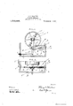
- Figure 1 is a side view of the starting mechanism as constructed according to this invention.
- Fig. 2 is a plan View of the starting mechanism.
- A is the main driving shaft of a motor of any approved construction, such as a gas engine.
- B is a ratchet toothed wheel formed in two halves or sections which are clamped upon one end portion ofthe shaft A by This wheel is made in sections and is provided with clamping bolts so that it can be applied to any existing engine without being bored to accurately fit its shaft and so that a key-way does not have to be cut in the shaft.
- C is the starting lever provided at one end with a bearing (1 made in two sections and provided with bolts 0 for securing them together.
- the bearing 0 is journaled loose on the shaft A. adjacent to the wheel B.
- l is a pawl which is pivoted to the lever (l by a pin (1, and c is a spring of moderate strength for causing the pawl to engage with the teeth ol the ratchet wheel when required.
- the pawl I) has an arm or exten sion (1 on the other side of its pivot from its point.
- l is a curved trip which is secured to a bracket F by means of bolts
- the bracket F is secured to a support (it which may be a portion of the frame of the engine or any frammwirk or stationary object secured adjacent to it.
- the trip is formed separate from the bracket and the bolts are arranged Specification of Letters Patent.
- the trip has a plate e which is provided with a longitudinal slot 9 so that the plate can be slid longitudinally 0n the bracket F to adjust the trip, when the nuts of the bolts f are slack. In this manner the bracket can be secured to any existing support, and the trip can be secured after being adjusted to project at any desired distance from the support.
- the spring H is a retracting spring which is considerably longer and stronger than the spring 6.
- One end of .the spring H is secured to a stationary object such as lug h on the bracket F, and its other end is connected to the operating lever C.
- the trip is arranged in the rearward path of the arm d, and the strong spring H retracts the starting lever, and also moves the pawl out of engagement with the teeth of the ratchet wheel by overcoming the force of the lighter spring 6.
- I is a flexible connection attached to the free end portion of the starting lever, and carried by a guide sheave or sheaves i to any desired point.
- the lever C When the engine is to be started, the lever C is moved sharply a few times in the direction of the arrow in Fig. 1.
- the pawl is disengaged automatically by the trip and strong spring as soon as the engine commences to work.
- the engine shaft can be provided with a starting crank in the ordinary way, if desired, in addition to the starting devices hereinbefore described.
- the trip E is arranged under the spring H, and it is adjusted longitudinally of the said spring so that the extent of its projection from the said frame can be provided for and also so that the spring will operate to release the pawl without jamming it against the trip.
- the spring retracts the pawl automatically, and enables the lever C to be operated from a distance by means of the flexible connection I which is pulled in the opposite direction from the spring and then released to permit the spring to act.
Landscapes
- Engineering & Computer Science (AREA)
- Chemical & Material Sciences (AREA)
- Combustion & Propulsion (AREA)
- Mechanical Engineering (AREA)
- General Engineering & Computer Science (AREA)
- Lighters Containing Fuel (AREA)
Description
1 H. P. WHALTON.
STARTING MECHANISM APPLICATION FILED MAR. 25, 1911.
Patented Dec. 5, 1911 WHM coo e o "manila nation of the parts hereinafter .means of bolts 7).
- UNITED s'TA ns PATENT OFFICE.
HILARY F. -WHALTON, OF KEY WEST, FLORIDA.
STARTING MECHANISM.
To all whom it may concern:
Be it known that I, HILARY F. WVHALTON, a citizen of the United States, residing at Key Vest, in the county of Monroe and State of Florida, have invented certain new and useful Improvements in Starting Mechanism; and I do hereby declare the following to be a full, clear, and exact description of the invention, such as will enable others skilled in the art to which it appertains to make and use the same.
This invention relates to starting mecha nism for motors, such as gas engines used on automobiles and aeroplanes; and it conin the novel construction and combifully described and claimed.
In the drawings, Figure 1 is a side view of the starting mechanism as constructed according to this invention. Fig. 2 is a plan View of the starting mechanism.
A is the main driving shaft of a motor of any approved construction, such as a gas engine.
B is a ratchet toothed wheel formed in two halves or sections which are clamped upon one end portion ofthe shaft A by This wheel is made in sections and is provided with clamping bolts so that it can be applied to any existing engine without being bored to accurately fit its shaft and so that a key-way does not have to be cut in the shaft.
C is the starting lever provided at one end with a bearing (1 made in two sections and provided with bolts 0 for securing them together. The bearing 0 is journaled loose on the shaft A. adjacent to the wheel B.
l) is a pawl which is pivoted to the lever (l by a pin (1, and c is a spring of moderate strength for causing the pawl to engage with the teeth ol the ratchet wheel when required. The pawl I) has an arm or exten sion (1 on the other side of its pivot from its point.
l) is a curved trip which is secured to a bracket F by means of bolts The bracket F is secured to a support (it which may be a portion of the frame of the engine or any frammwirk or stationary object secured adjacent to it. The trip is formed separate from the bracket and the bolts are arranged Specification of Letters Patent.
Application filed March 25, 1911.
Patented Dec. 5, 1911. Serial No. 616,920.
so as to permit its position to be adjusted. The trip has a plate e which is provided with a longitudinal slot 9 so that the plate can be slid longitudinally 0n the bracket F to adjust the trip, when the nuts of the bolts f are slack. In this manner the bracket can be secured to any existing support, and the trip can be secured after being adjusted to project at any desired distance from the support.
H is a retracting spring which is considerably longer and stronger than the spring 6. One end of .the spring H is secured to a stationary object such as lug h on the bracket F, and its other end is connected to the operating lever C.
The trip is arranged in the rearward path of the arm d, and the strong spring H retracts the starting lever, and also moves the pawl out of engagement with the teeth of the ratchet wheel by overcoming the force of the lighter spring 6.
I is a flexible connection attached to the free end portion of the starting lever, and carried by a guide sheave or sheaves i to any desired point.
When the engine is to be started, the lever C is moved sharply a few times in the direction of the arrow in Fig. 1. The pawl is disengaged automatically by the trip and strong spring as soon as the engine commences to work. The engine shaft can be provided with a starting crank in the ordinary way, if desired, in addition to the starting devices hereinbefore described. The trip E is arranged under the spring H, and it is adjusted longitudinally of the said spring so that the extent of its projection from the said frame can be provided for and also so that the spring will operate to release the pawl without jamming it against the trip. The spring retracts the pawl automatically, and enables the lever C to be operated from a distance by means of the flexible connection I which is pulled in the opposite direction from the spring and then released to permit the spring to act.
lVhat I claim is:
The combination, with an engine shaft, of a toothed wheel secured on the shaft, a starting lever mounted on the shaft, a pawl pivoted to the lever and engaging with the said Wheel, a stationary trip a spring which I connection attached to the said lever and moves the lever in one direction and presses enabling it to be operated from a distance. 10 it against the said trip thereby disengaging i In testimony whereof I have afiixed my it from the said wheel, a support, a bracket signature in the presence of two Witnesses. secured to the said support, means for con- HILARY F. \VHALTON. necting the said trip to the said bracket and permitting the trip to be adjusted longitudinally of the said spring, and a flexible \Vitnesses JAS. WM. HAsKms, F. M. PAGE.
Priority Applications (1)
| Application Number | Priority Date | Filing Date | Title |
|---|---|---|---|
| US61692011A US1010835A (en) | 1911-03-25 | 1911-03-25 | Starting mechanism. |
Applications Claiming Priority (1)
| Application Number | Priority Date | Filing Date | Title |
|---|---|---|---|
| US61692011A US1010835A (en) | 1911-03-25 | 1911-03-25 | Starting mechanism. |
Publications (1)
| Publication Number | Publication Date |
|---|---|
| US1010835A true US1010835A (en) | 1911-12-05 |
Family
ID=3079145
Family Applications (1)
| Application Number | Title | Priority Date | Filing Date |
|---|---|---|---|
| US61692011A Expired - Lifetime US1010835A (en) | 1911-03-25 | 1911-03-25 | Starting mechanism. |
Country Status (1)
| Country | Link |
|---|---|
| US (1) | US1010835A (en) |
Cited By (3)
| Publication number | Priority date | Publication date | Assignee | Title |
|---|---|---|---|---|
| US2793868A (en) * | 1950-10-30 | 1957-05-28 | Winona Tool Mfg Company | Carrier cart provided with stair climbing endless treads |
| US2808729A (en) * | 1952-06-30 | 1957-10-08 | Renault | Ratchet devices for incorporation in transmission systems for vehicles |
| US5684345A (en) * | 1994-12-16 | 1997-11-04 | Elektra Beckum Ag | Single phase induction motor as the drive of a high pressure cleaning device |
-
1911
- 1911-03-25 US US61692011A patent/US1010835A/en not_active Expired - Lifetime
Cited By (3)
| Publication number | Priority date | Publication date | Assignee | Title |
|---|---|---|---|---|
| US2793868A (en) * | 1950-10-30 | 1957-05-28 | Winona Tool Mfg Company | Carrier cart provided with stair climbing endless treads |
| US2808729A (en) * | 1952-06-30 | 1957-10-08 | Renault | Ratchet devices for incorporation in transmission systems for vehicles |
| US5684345A (en) * | 1994-12-16 | 1997-11-04 | Elektra Beckum Ag | Single phase induction motor as the drive of a high pressure cleaning device |
Similar Documents
| Publication | Publication Date | Title |
|---|---|---|
| US447780A (en) | Gar brake and starter | |
| US1010835A (en) | Starting mechanism. | |
| US1004984A (en) | Gas-engine starter. | |
| US1288362A (en) | Device for starting explosive-engines. | |
| US1037466A (en) | Starter for explosion-engines and self-propelled vehicles. | |
| US1160474A (en) | Starting device for motor-vehicles. | |
| US1125325A (en) | Pawl-and-ratchet mechanism. | |
| US1179815A (en) | Cranking device for automobiles. | |
| US1142889A (en) | Starting device for gas-engines. | |
| US1217466A (en) | Mechanical starter for automobile-engines. | |
| US1166105A (en) | Starting-gear for motor-cars. | |
| US991135A (en) | Cranking means for automobiles. | |
| US1065627A (en) | Driving mechanism for polishing devices. | |
| US1028624A (en) | Automobile-starter. | |
| US1643334A (en) | Brake lock | |
| US222492A (en) | Improvement in car-jacks | |
| US1010233A (en) | Starting mechanism for explosion-engines. | |
| US1176737A (en) | Explosive-engine starter. | |
| US1178989A (en) | Starter for internal-combustion engines. | |
| US1153085A (en) | Starter for explosive-engines. | |
| US1026534A (en) | Auto cranking device. | |
| US1249971A (en) | Starter for automobile-engines. | |
| US1412397A (en) | Brake-locking device | |
| US1101957A (en) | Engine-starter. | |
| US1148635A (en) | Starting device for internal-combustion engines. |