US10052150B2 - Device for endometrial ablation having an expandable seal for a cervical canal - Google Patents
Device for endometrial ablation having an expandable seal for a cervical canal Download PDFInfo
- Publication number
- US10052150B2 US10052150B2 US15/220,241 US201615220241A US10052150B2 US 10052150 B2 US10052150 B2 US 10052150B2 US 201615220241 A US201615220241 A US 201615220241A US 10052150 B2 US10052150 B2 US 10052150B2
- Authority
- US
- United States
- Prior art keywords
- seal
- sleeve
- wall
- dielectric structure
- thin
- Prior art date
- Legal status (The legal status is an assumption and is not a legal conclusion. Google has not performed a legal analysis and makes no representation as to the accuracy of the status listed.)
- Active
Links
Images


Classifications
-
- A—HUMAN NECESSITIES
- A61—MEDICAL OR VETERINARY SCIENCE; HYGIENE
- A61B—DIAGNOSIS; SURGERY; IDENTIFICATION
- A61B18/00—Surgical instruments, devices or methods for transferring non-mechanical forms of energy to or from the body
- A61B18/04—Surgical instruments, devices or methods for transferring non-mechanical forms of energy to or from the body by heating
- A61B18/12—Surgical instruments, devices or methods for transferring non-mechanical forms of energy to or from the body by heating by passing a current through the tissue to be heated, e.g. high-frequency current
- A61B18/14—Probes or electrodes therefor
- A61B18/1485—Probes or electrodes therefor having a short rigid shaft for accessing the inner body through natural openings
-
- A—HUMAN NECESSITIES
- A61—MEDICAL OR VETERINARY SCIENCE; HYGIENE
- A61B—DIAGNOSIS; SURGERY; IDENTIFICATION
- A61B18/00—Surgical instruments, devices or methods for transferring non-mechanical forms of energy to or from the body
- A61B18/04—Surgical instruments, devices or methods for transferring non-mechanical forms of energy to or from the body by heating
- A61B18/042—Surgical instruments, devices or methods for transferring non-mechanical forms of energy to or from the body by heating using additional gas becoming plasma
-
- A—HUMAN NECESSITIES
- A61—MEDICAL OR VETERINARY SCIENCE; HYGIENE
- A61B—DIAGNOSIS; SURGERY; IDENTIFICATION
- A61B18/00—Surgical instruments, devices or methods for transferring non-mechanical forms of energy to or from the body
- A61B2018/00053—Mechanical features of the instrument of device
- A61B2018/00166—Multiple lumina
-
- A—HUMAN NECESSITIES
- A61—MEDICAL OR VETERINARY SCIENCE; HYGIENE
- A61B—DIAGNOSIS; SURGERY; IDENTIFICATION
- A61B18/00—Surgical instruments, devices or methods for transferring non-mechanical forms of energy to or from the body
- A61B2018/00053—Mechanical features of the instrument of device
- A61B2018/00214—Expandable means emitting energy, e.g. by elements carried thereon
- A61B2018/0022—Balloons
- A61B2018/00232—Balloons having an irregular shape
-
- A—HUMAN NECESSITIES
- A61—MEDICAL OR VETERINARY SCIENCE; HYGIENE
- A61B—DIAGNOSIS; SURGERY; IDENTIFICATION
- A61B18/00—Surgical instruments, devices or methods for transferring non-mechanical forms of energy to or from the body
- A61B2018/00053—Mechanical features of the instrument of device
- A61B2018/00273—Anchoring means for temporary attachment of a device to tissue
- A61B2018/00279—Anchoring means for temporary attachment of a device to tissue deployable
- A61B2018/00285—Balloons
-
- A—HUMAN NECESSITIES
- A61—MEDICAL OR VETERINARY SCIENCE; HYGIENE
- A61B—DIAGNOSIS; SURGERY; IDENTIFICATION
- A61B18/00—Surgical instruments, devices or methods for transferring non-mechanical forms of energy to or from the body
- A61B2018/00315—Surgical instruments, devices or methods for transferring non-mechanical forms of energy to or from the body for treatment of particular body parts
- A61B2018/00559—Female reproductive organs
-
- A—HUMAN NECESSITIES
- A61—MEDICAL OR VETERINARY SCIENCE; HYGIENE
- A61B—DIAGNOSIS; SURGERY; IDENTIFICATION
- A61B18/00—Surgical instruments, devices or methods for transferring non-mechanical forms of energy to or from the body
- A61B2018/00571—Surgical instruments, devices or methods for transferring non-mechanical forms of energy to or from the body for achieving a particular surgical effect
- A61B2018/00577—Ablation
-
- A—HUMAN NECESSITIES
- A61—MEDICAL OR VETERINARY SCIENCE; HYGIENE
- A61B—DIAGNOSIS; SURGERY; IDENTIFICATION
- A61B18/00—Surgical instruments, devices or methods for transferring non-mechanical forms of energy to or from the body
- A61B2018/00636—Sensing and controlling the application of energy
- A61B2018/00642—Sensing and controlling the application of energy with feedback, i.e. closed loop control
-
- A—HUMAN NECESSITIES
- A61—MEDICAL OR VETERINARY SCIENCE; HYGIENE
- A61B—DIAGNOSIS; SURGERY; IDENTIFICATION
- A61B18/00—Surgical instruments, devices or methods for transferring non-mechanical forms of energy to or from the body
- A61B2018/00636—Sensing and controlling the application of energy
- A61B2018/00696—Controlled or regulated parameters
- A61B2018/00702—Power or energy
-
- A—HUMAN NECESSITIES
- A61—MEDICAL OR VETERINARY SCIENCE; HYGIENE
- A61B—DIAGNOSIS; SURGERY; IDENTIFICATION
- A61B18/00—Surgical instruments, devices or methods for transferring non-mechanical forms of energy to or from the body
- A61B2018/00636—Sensing and controlling the application of energy
- A61B2018/00773—Sensed parameters
- A61B2018/00791—Temperature
-
- A—HUMAN NECESSITIES
- A61—MEDICAL OR VETERINARY SCIENCE; HYGIENE
- A61B—DIAGNOSIS; SURGERY; IDENTIFICATION
- A61B18/00—Surgical instruments, devices or methods for transferring non-mechanical forms of energy to or from the body
- A61B2018/00636—Sensing and controlling the application of energy
- A61B2018/00773—Sensed parameters
- A61B2018/00827—Current
-
- A—HUMAN NECESSITIES
- A61—MEDICAL OR VETERINARY SCIENCE; HYGIENE
- A61B—DIAGNOSIS; SURGERY; IDENTIFICATION
- A61B18/00—Surgical instruments, devices or methods for transferring non-mechanical forms of energy to or from the body
- A61B2018/00636—Sensing and controlling the application of energy
- A61B2018/00773—Sensed parameters
- A61B2018/00863—Fluid flow
-
- A—HUMAN NECESSITIES
- A61—MEDICAL OR VETERINARY SCIENCE; HYGIENE
- A61B—DIAGNOSIS; SURGERY; IDENTIFICATION
- A61B18/00—Surgical instruments, devices or methods for transferring non-mechanical forms of energy to or from the body
- A61B2018/00636—Sensing and controlling the application of energy
- A61B2018/00773—Sensed parameters
- A61B2018/00875—Resistance or impedance
-
- A—HUMAN NECESSITIES
- A61—MEDICAL OR VETERINARY SCIENCE; HYGIENE
- A61B—DIAGNOSIS; SURGERY; IDENTIFICATION
- A61B18/00—Surgical instruments, devices or methods for transferring non-mechanical forms of energy to or from the body
- A61B2018/00636—Sensing and controlling the application of energy
- A61B2018/00773—Sensed parameters
- A61B2018/00892—Voltage
-
- A—HUMAN NECESSITIES
- A61—MEDICAL OR VETERINARY SCIENCE; HYGIENE
- A61B—DIAGNOSIS; SURGERY; IDENTIFICATION
- A61B18/00—Surgical instruments, devices or methods for transferring non-mechanical forms of energy to or from the body
- A61B18/04—Surgical instruments, devices or methods for transferring non-mechanical forms of energy to or from the body by heating
- A61B18/12—Surgical instruments, devices or methods for transferring non-mechanical forms of energy to or from the body by heating by passing a current through the tissue to be heated, e.g. high-frequency current
- A61B18/14—Probes or electrodes therefor
- A61B2018/147—Electrodes transferring energy by capacitive coupling, i.e. with a dielectricum between electrode and target tissue
Definitions
- the present invention relates to electrosurgical methods and devices for global endometrial ablation in a treatment of menorrhagia. More particularly, the present invention relates to applying radiofrequency current to endometrial tissue by means of capacitively coupling the current through an expandable, thin-wall dielectric member enclosing an ionized gas.
- a variety of devices have been developed or proposed for endometrial ablation. Of relevance to the present invention, a variety of radiofrequency ablation devices have been proposed including solid electrodes, balloon electrodes, metalized fabric electrodes, and the like. While often effective, many of the prior electrode designs have suffered from one or more deficiencies, such as relatively slow treatment times, incomplete treatments, non-uniform ablation depths, and risk of injury to adjacent organs.
- U.S. Pat. Nos. 5,769,880; 6,296,639; 6,663,626; and 6,813,520 describe intrauterine ablation devices formed from a permeable mesh defining electrodes for the application of radiofrequency energy to ablate uterine tissue.
- U.S. Pat. No. 4,979,948 describes a balloon filled with an electrolyte solution for applying radiofrequency current to a mucosal layer via capacitive coupling.
- US 2008/097425 having common inventorship with the present application, describes delivering a pressurized flow of a liquid medium which carries a radiofrequency current to tissue, where the liquid is ignited into a plasma as it passes through flow orifices.
- U.S. Pat. No. 6,041,260 describes radiofrequency electrodes distributed over the exterior surface of a balloon which is inflated in a body cavity to be treated.
- U.S. Pat. No. 7,371,231 and US 2009/054892 describe a conductive balloon having an exterior surface which acts as an electrode for performing endometrial ablation.
- U.S. Pat. No. 5,191,883 describes bipolar heating of a medium within a balloon for thermal ablation.
- U.S. Pat. Nos. 6,736,811 and 5,925,038 show an inflatable conductive electrode.
- the present invention provides methods, systems and devices for evaluating the integrity of a uterine cavity.
- the uterine cavity may be perforated or otherwise damaged by the transcervical introduction of probes and instruments into the uterine cavity. If the uterine wall is perforated, it would be preferable to defer any ablation treatment until the uterine wall is healed.
- a method of the invention comprises introducing transcervically a probe into a patient's uterine cavity, providing a flow of a fluid (e.g., CO.sub.2) through the probe into the uterine cavity and monitoring the rate of the flow to characterize the uterine cavity as perforated or non-perforated based on a change in the flow rate.
- a fluid e.g., CO.sub.2
- Embodiments herein provide a system for treating uterine tissue, comprising an expandable RF energy delivery surface for positioning in a uterine cavity; an RF source configured to deliver current across the surface; and a sealing structure disposed adjacent the energy delivery surface and configured for positioning in and sealing a cervical canal.
- the sealing structure may be, for example, an elongated bellows-like member with a compliant wall.
- the sealing structure has a longitudinal axis, and has a repose state with a plurality of annular ridges for engaging tissue surrounding a cervical canal.
- the sealing structure can be axially stretched to provide a reduced cross section for insertion in the patient's uterine canal.
- the sealing structure is elongated with a distal portion having a greater cross section in a repose state, and a proximal portion with a lesser cross section in a repose state.
- the sealing structure may be carried concentrically around a distal portion of a sleeve assembly or support member that carries the RF energy delivery surface of the endometrial ablation system.
- the energy delivery surface comprises a wall surrounding an interior chamber.
- the wall may include at least partly a dielectric.
- the wall may further include an electrode.
- the interior chamber may be fluid-tight.
- a method of treating uterine tissue comprising expanding a RF energy delivery surface within a patient's uterine cavity; expanding an expandable member in the patient's cervical canal; and activating an RF source configured to deliver current across the surface to ablate endometrial tissue.
- expanding the RF energy delivery surface comprises expanding a frame supporting the surface.
- FIG. 3 is a block diagram of components of one electrosurgical system corresponding to the invention.
- FIG. 5 is an enlarged perspective view of the expanded thin-wall dielectric structure, showing an expandable-collapsible frame with the thin dielectric wall in phantom view.
- FIG. 7 is a sectional view of an introducer sleeve showing various lumens of the introducer sleeve taken along line 7 - 7 of FIG. 6 .
- FIG. 8A is an enlarged schematic view of an aspect of a method of the invention illustrating the step introducing an introducer sleeve into a patient's uterus.
- FIG. 8B is a schematic view of a subsequent step of retracting the introducer sleeve to expose a collapsed thin-wall dielectric structure and internal frame in the uterine cavity.
- FIG. 8C is a schematic view of subsequent steps of the method, including, (i) actuating the internal frame to move the a collapsed thin-wall dielectric structure to an expanded configuration, (ii) inflating a cervical-sealing balloon carried on the introducer sleeve, and (iii) actuating gas flows and applying RF energy to contemporaneously ionize the gas in the interior chamber and cause capacitive coupling of current through the thin-wall dielectric structure to cause ohmic heating in the engaged tissue indicated by current flow paths.
- FIG. 10 is an enlarged cut-away view of a portion of the expanded thin-wall dielectric structure of FIG. 9 showing the electrode configuration.
- FIG. 11 is a diagram of a radiofrequency energy delivery apparatus and method corresponding to the invention.
- FIG. 13A is a schematic representation of an indicator mechanism in the handle of the ablation device of FIGS. 1-2 for indicating a first degree of expansion of the dielectric structure in a range shown in FIG. 12 .
- FIG. 13B is a schematic representation of the indicator mechanism of FIG. 13A indicating a second the degree of expansion of the dielectric structure.
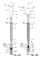
- FIG. 14 is a perspective view of an alternative working end of an endometrial ablation system with an elongated, elastomeric bellows-like seal for sealing the patient's cervical canal.
- FIG. 15A is a cut-away view of the cervical seal of FIG. 14 in a repose shape.
- FIG. 15B is a cut-away view of the cervical seal of FIGS. 14 and 15A in a stretched, tensioned shape.
- FIG. 16A is a schematic view of a method of the invention illustrating the step introducing an introducer sleeve with the seal of FIG. 14 into a patient's uterus.
- FIG. 16B is a schematic view of a subsequent step of deploying the seal of FIG. 14 in the patient's cervical canal.
- FIG. 17 is a side view of another embodiment of an elongated, elastomeric bellows-like seal for sealing the patient's cervical canal.
- FIG. 18 is a side view of another embodiment of an elongated, elastomeric bellows-like seal for sealing the patient's cervical canal.
- FIG. 19 is a side view of another embodiment of an elongated, elastomeric bellows-like seal for sealing the patient's cervical canal.
- FIG. 20 is a side view of another embodiment of an elongated, elastomeric bellows-like seal for sealing the patient's cervical canal.
- an electrosurgical ablation system comprising an elongated introducer member for accessing a patient's uterine cavity with a working end that deploys an expandable thin-wall dielectric structure containing an electrically non-conductive gas as a dielectric.
- an interior chamber of the thin-wall dielectric structure contains a circulating neutral gas such as argon.
- An RF power source provides current that is coupled to the neutral gas flow by a first polarity electrode disposed within the interior chamber and a second polarity electrode at an exterior of the working end.
- the gas flow which is converted to a conductive plasma by an electrode arrangement, functions as a switching mechanism that permits current flow to engaged endometrial tissue only when the voltage across the combination of the gas, the thin-wall dielectric structure and the engaged tissue reaches a threshold that causes capacitive coupling across the thin-wall dielectric material.
- capacitively coupling current to tissue in this manner, the system provides a substantially uniform tissue effect within all tissue in contact with the expanded dielectric structure. Further, the invention allows the neutral gas to be created contemporaneously with the capacitive coupling of current to tissue.
- a plasma consists of a state of matter in which electrons in a neutral gas are stripped or “ionized” from their molecules or atoms. Such plasmas can be formed by application of an electric field or by high temperatures. In a neutral gas, electrical conductivity is non-existent or very low. Neutral gases act as a dielectric or insulator until the electric field reaches a breakdown value, freeing the electrons from the atoms in an avalanche process thus forming a plasma. Such a plasma provides mobile electrons and positive ions, and acts as a conductor which supports electric currents and can form spark or arc. Due to their lower mass, the electrons in a plasma accelerate more quickly in response to an electric field than the heavier positive ions, and hence carry the bulk of the current.
- FIG. 1 depicts one embodiment of an electrosurgical ablation system 100 configured for endometrial ablation.
- the system 100 includes a hand-held apparatus 105 with a proximal handle 106 shaped for grasping with a human hand that is coupled to an elongated introducer sleeve 110 having axis 111 that extends to a distal end 112 .
- the introducer sleeve 110 can be fabricated of a thin-wall plastic, composite, ceramic or metal in a round or oval cross-section having a diameter or major axis ranging from about 4 mm to 8 mm in at least a distal portion of the sleeve that accesses the uterine cavity.
- the handle 106 is fabricated of an electrically insulative material such as a molded plastic with a pistol-grip having first and second portions, 114 a and 114 b , that can be squeezed toward one another to translate an elongated translatable sleeve 115 which is housed in a bore 120 in the elongated introducer sleeve 110 .
- a working end 122 can be deployed from a first retracted position ( FIG. 1 ) in the distal portion of bore 120 in introducer sleeve 110 to an extended position as shown in FIG. 2 .
- FIG. 2 it can be seen that the first and second handle portions, 114 a and 114 b , are in a second actuated position with the working end 122 deployed from the bore 120 in introducer sleeve 110 .
- FIGS. 2 and 3 shows that ablation system 100 includes an RF energy source 130 A and RF controller 130 B in a control unit 135 .
- the RF energy source 130 A is connected to the hand-held device 105 by a flexible conduit 136 with a plug-in connector 137 configured with a gas inflow channel, a gas outflow channel, and first and second electrical leads for connecting to receiving connector 138 in the control unit 135 .
- the control unit 135 further comprises a neutral gas inflow source 140 A, gas flow controller 140 B and optional vacuum or negative pressure source 145 to provide controlled gas inflows and gas outflows to and from the working end 122 .
- the control unit 135 further includes a balloon inflation source 148 for inflating an expandable sealing balloon 225 carried on introducer sleeve 110 as described further below.
- the working end 122 includes a flexible, thin-wall member or structure 150 of a dielectric material that when expanded has a triangular shape configured for contacting the patient's endometrial lining that is targeted for ablation.
- the dielectric structure 150 comprises a thin-wall material such as silicone with a fluid-tight interior chamber 152 .
- an expandable-collapsible frame assembly 155 is disposed in the interior chamber.
- the dielectric structure may be expanded by a neutral gas without a frame, but using a frame offers a number of advantages.
- the uterine cavity is flattened with the opposing walls in contact with one another. Expanding a balloon-type member may cause undesirable pain or spasms. For this reason, a flat structure that is expanded by a frame is better suited for deployment in the uterine cavity.
- the neutral gas is converted to a conductive plasma at a very low pressure controlled by gas inflows and gas outflows—so that any pressurization of a balloon-type member with the neutral gas may exceed a desired pressure range and would require complex controls of gas inflows and gas outflows.
- the frame provides an electrode for contact with the neutral gas in the interior chamber 152 of the dielectric structure 150 , and the frame 155 extends into all regions of the interior chamber to insure electrode exposure to all regions of the neutral gas and plasma.
- the frame 155 can be constructed of any flexible material with at least portions of the frame functioning as spring elements to move the thin-wall structure 150 from a collapsed configuration ( FIG. 1 ) to an expanded, deployed configuration ( FIG.
- the frame 155 comprises stainless steel elements 158 a , 158 b and 160 a and 160 b that function akin to leaf springs.
- the frame can be a stainless steel such as 316 SS, 17A SS, 420 SS, 440 SS or the frame can be a NiTi material.
- the frame preferably extends along a single plane, yet remains thin transverse to the plane, so that the frame may expand into the uterine cavity.
- the frame elements can have a thickness ranging from about 0.005′′ to 0.025′′. As can be seen in FIGS.
- the proximal ends 162 a and 162 b of spring elements 158 a , 158 b are fixed (e.g., by welds 164 ) to the distal end 165 of sleeve member 115 .
- the proximal ends 166 a and 166 b of spring elements 160 a , 160 b are welded to distal portion 168 of a secondary translatable sleeve 170 that can be extended from bore 175 in translatable sleeve 115 .
- the secondary translatable sleeve 170 is dimensioned for a loose fit in bore 175 to allow gas flows within bore 175 .
- FIGS. 5 and 6 further illustrate the distal ends 176 a and 176 b of spring elements 158 a , 158 b are welded to distal ends 178 a and 178 b of spring elements 160 a and 160 b to thus provide a frame 155 that can be moved from a linear shape (see FIG. 1 ) to an expanded triangular shape ( FIGS. 5 and 6 ).
- the bore 175 in sleeve 115 and bore 180 in secondary translatable sleeve 170 function as gas outflow and gas inflow lumens, respectively.
- the gas inflow lumen can comprise any single lumen or plurality of lumens in either sleeve 115 or sleeve 170 or another sleeve, or other parts of the frame 155 or the at least one gas flow lumen can be formed into a wall of dielectric structure 150 .
- gas inflows are provided through bore 180 in sleeve 170
- gas outflows are provided in bore 175 of sleeve 115 .
- FIGS. 5 and 6 further show that a rounded bumper element 185 is provided at the distal end of sleeve 170 to insure that no sharp edges of the distal end of sleeve 170 can contact the inside of the thin dielectric wall 150 .
- the bumper element 185 is silicone, but it could also comprise a rounded metal element.
- FIGS. 5 and 6 also show that a plurality of gas inflow ports 188 can be provided along a length of in sleeve 170 in chamber 152 , as well as a port 190 in the distal end of sleeve 170 and bumper element 185 .
- the sectional view of FIG. 7 also shows the gas flow passageways within the interior of introducer sleeve 110 .
- first and second handle portions, 114 a and 114 b (i) initially causes movement of the assembly of sleeves 115 and 170 relative to bore 120 of introducer sleeve 110 , and (ii) secondarily causes extension of sleeve 170 from bore 175 in sleeve 115 to expand the frame 155 into the triangular shape of FIG. 5 .
- the dimensions of the triangular shape are suited for a patient uterine cavity, and for example can have an axial length A ranging from 4 to 10 cm and a maximum width B at the distal end ranging from about 2 to 5 cm.
- the thickness C of the thin-wall structure 150 can be from 1 to 4 mm as determined by the dimensions of spring elements 158 a , 158 b , 160 a and 160 b of frame assembly 155 .
- the frame assembly 155 can comprise round wire elements, flat spring elements, of any suitable metal or polymer that can provide opening forces to move thin-wall structure 150 from a collapsed configuration to an expanded configuration within the patient uterus.
- some elements of the frame 155 can be spring elements and some elements can be flexible without inherent spring characteristics.
- the working end embodiment of FIGS. 2, 5 and 6 has a thin-wall structure 150 that is formed of a dielectric material such as silicone that permits capacitive coupling of current to engaged tissue while the frame assembly 155 provides structural support to position the thin-wall structure 150 against tissue. Further, gas inflows into the interior chamber 152 of the thin-wall structure can assist in supporting the dielectric wall so as to contact endometrial tissue.
- the dielectric thin-wall structure 150 can be free from fixation to the frame assembly 155 , or can be bonded to an outward-facing portion or portions of frame elements 158 a and 158 b .
- the proximal end 182 of thin-wall structure 150 is bonded to the exterior of the distal end of sleeve 115 to thus provide a sealed, fluid-tight interior chamber 152 ( FIG. 5 ).
- the gas inflow source 140 A comprises one or more compressed gas cartridges that communicate with flexible conduit 136 through plug-in connector 137 and receiving connector 138 in the control unit 135 ( FIGS. 1-2 ).
- the gas inflows from source 140 A flow through bore 180 in sleeve 170 to open terminations 188 and 190 therein to flow into interior chamber 152 .
- a vacuum source 145 is connected through conduit 136 and connector 137 to allow circulation of gas flow through the interior chamber 152 of the thin-wall dielectric structure 150 .
- gas outflows communicate with vacuum source 145 through open end 200 of bore 175 in sleeve 115 . Referring to FIG.
- frame elements 158 a and 158 b are configured with a plurality of apertures 202 to allow for gas flows through all interior portions of the frame elements, and thus gas inflows from open terminations 188 , 190 in bore 180 are free to circulated through interior chamber 152 to return to an outflow path through open end 200 of bore 175 of sleeve 115 .
- the gas inflow source 140 A is connected to a gas flow or circulation controller 140 B which controls a pressure regulator 205 and also controls vacuum source 145 which is adapted for assisting in circulation of the gas.
- the frame elements can be configured with apertures, notched edges or any other configurations that allow for effective circulation of a gas through interior chamber 152 of the thin-wall structure 150 between the inflow and outflow passageways.
- FIGS. 5 and 6 illustrate opposing polarity electrodes of the system 100 that are configured to convert a flow of neutral gas in chamber 152 into a plasma 208 ( FIG. 6 ) and to allow capacitive coupling of current through a wall 210 of the thin-wall dielectric structure 150 to endometrial tissue in contact with the wall 210 .
- the electrosurgical methods of capacitively coupling RF current across a plasma 208 and dielectric wall 210 are described in U.S. patent application Ser. No. 12/541,043; filed Aug. 13, 2009 and U.S. application Ser. No. 12/541,050, referenced above.
- the first polarity electrode 215 is within interior chamber 152 to contact the neutral gas flow and comprises the frame assembly 155 that is fabricated of an electrically conductive stainless steel. In another embodiment, the first polarity electrode can be any element disposed within the interior chamber 152 , or extendable into interior chamber 152 .
- the first polarity electrode 215 is electrically coupled to sleeves 115 and 170 which extends through the introducer sleeve 110 to handle 106 and conduit 136 and is connected to a first pole of the RF source energy source 130 A and controller 130 B.
- a second polarity electrode 220 is external of the internal chamber 152 and in one embodiment the electrode is spaced apart from wall 210 of the thin-wall dielectric structure 150 .
- the second polarity electrode 220 comprises a surface element of an expandable balloon member 225 carried by introducer sleeve 110 .
- the second polarity electrode 220 is coupled by a lead (not shown) that extends through the introducer sleeve 110 and conduit 136 to a second pole of the RF source 130 A.
- second polarity electrode 220 can be positioned on sleeve 110 or can be attached to surface portions of the expandable thin-wall dielectric structure 150 , as will be described below, to provide suitable contact with body tissue to allow the electrosurgical ablation of the method of the invention.
- the second polarity electrode 220 can comprise a thin conductive metallic film, thin metal wires, a conductive flexible polymer or a polymeric positive temperature coefficient material.
- the expandable member 225 comprises a thin-wall compliant balloon having a length of about 1 cm to 6 cm that can be expanded to seal the cervical canal.
- the balloon 225 can be inflated with a gas or liquid by any inflation source 148 , and can comprise a syringe mechanism controlled manually or by control unit 135 .
- the balloon inflation source 148 is in fluid communication with an inflation lumen 228 in introducer sleeve 110 that extends to an inflation chamber of balloon 225 (see FIG. 7 ).
- control unit 135 can include a display 230 and touch screen or other controls 232 for setting and controlling operational parameters such as treatment time intervals, treatment algorithms, gas flows, power levels and the like. Suitable gases for use in the system include argon, other noble gases and mixtures thereof.
- a footswitch 235 is coupled to the control unit 135 for actuating the system.
- FIGS. 3 and 4 schematically depict the system 100 , subsystems and components that are configured for an endometrial ablation system.
- RF energy source 130 A and circuitry is controlled by a controller 130 B.
- the system can include feedback control systems that include signals relating to operating parameters of the plasma in interior chamber 152 of the dielectric structure 150 .
- feedback signals can be provided from at least one temperature sensor 240 in the interior chamber 152 of the dielectric structure 150 , from a pressure sensor within, or in communication, with interior chamber 152 , and/or from a gas flow rate sensor in an inflow or outflow channel of the system.
- FIG. 4 is a schematic block diagram of the flow control components relating to the flow of gas media through the system 100 and hand-held device 105 .
- a pressurized gas source 140 A is linked to a downstream pressure regulator 205 , an inflow proportional valve 246 , flow meter 248 and normally closed solenoid valve 250 .
- the valve 250 is actuated by the system operator which then allows a flow of a neutral gas from gas source 140 A to circulate through flexible conduit 136 and the device 105 .
- the gas outflow side of the system includes a normally open solenoid valve 260 , outflow proportional valve 262 and flow meter 264 that communicate with vacuum pump or source 145 .
- the gas can be exhausted into the environment or into a containment system.
- a temperature sensor 270 (e.g., thermocouple) is shown in FIG. 4 that is configured for monitoring the temperature of outflow gases.
- FIG. 4 further depicts an optional subsystem 275 which comprises a vacuum source 280 and solenoid valve 285 coupled to the controller 140 B for suctioning steam from a uterine cavity 302 at an exterior of the dielectric structure 150 during a treatment interval.
- the flow passageway from the uterine cavity 302 can be through bore 120 in sleeve 110 (see FIGS. 2, 6 and 7 ) or another lumen in a wall of sleeve 110 can be provided.
- FIGS. 8A-8D schematically illustrate a method of the invention wherein (i) the thin-wall dielectric structure 150 is deployed within a patient uterus and (ii) RF current is applied to a contained neutral gas volume in the interior chamber 152 to contemporaneously create a plasma 208 in the chamber and capacitively couple current through the thin dielectric wall 210 to apply ablative energy to the endometrial lining to accomplish global endometrial ablation.
- FIG. 8A illustrates a patient uterus 300 with uterine cavity 302 surrounded by endometrium 306 and myometrium 310 .
- the external cervical os 312 is the opening of the cervix 314 into the vagina 316 .
- the internal os or opening 320 is a region of the cervical canal that opens to the uterine cavity 302 .
- FIG. 8A depicts a first step of a method of the invention wherein the physician has introduced a distal portion of sleeve 110 into the uterine cavity 302 . The physician gently can advance the sleeve 110 until its distal tip contacts the fundus 324 of the uterus. Prior to insertion of the device, the physician can optionally introduce a sounding instrument into the uterine cavity to determine uterine dimensions, for example from the internal os 320 to fundus 324 .
- FIG. 8B illustrates a subsequent step of a method of the invention wherein the physician begins to actuate the first and second handle portions, 114 a and 114 b , and the introducer sleeve 110 retracts in the proximal direction to expose the collapsed frame 155 and thin-wall structure 150 within the uterine cavity 302 .
- the sleeve 110 can be retracted to expose a selected axial length of thin-wall dielectric structure 150 , which can be determined by markings 330 on sleeve 115 (see FIG. 1 ) which indicate the axial travel of sleeve 115 relative to sleeve 170 and thus directly related to the length of deployed thin-wall structure 150 .
- FIG. 2 depicts the handle portions 114 a and 114 b fully approximated thus deploying the thin-wall structure to its maximum length.
- the spring frame elements 158 a , 158 b , 160 a and 160 b move the dielectric structure 150 from a non-expanded position to an expanded position in the uterine cavity as depicted by the profiles in dashed lines.
- the spring force of the frame 155 will expand the dielectric structure 150 until limited by the dimensions of the uterine cavity.
- FIG. 8C illustrates several subsequent steps of a method of the invention.
- FIG. 8C first depicts the physician continuing to actuate the first and second handle portions, 114 a and 114 b , which further actuates the frame 155 (see FIGS. 5-6 ) to expand the frame 155 and thin-wall structure 150 to a deployed triangular shape to contact the patient's endometrial lining 306 .
- the physician can slightly rotate and move the expanding dielectric structure 150 back and forth as the structure is opened to insure it is opened to the desired extent.
- the physician can actuate handle portions, 114 a and 114 b , a selected degree which causes a select length of travel of sleeve 170 relative to sleeve 115 which in turn opens the frame 155 to a selected degree.
- the selected actuation of sleeve 170 relative to sleeve 115 also controls the length of dielectric structure deployed from sleeve 110 into the uterine cavity.
- the thin-wall structure 150 can be deployed in the uterine cavity with a selected length, and the spring force of the elements of frame 155 will open the structure 150 to a selected triangular shape to contact or engage the endometrium 306 .
- the expandable thin-wall structure 150 is urged toward and maintained in an open position by the spring force of elements of the frame 155 .
- the handle 106 includes a locking mechanism with finger-actuated sliders 332 on either side of the handle that engage a grip-lock element against a notch in housing 333 coupled to introducer sleeve 110 ( FIG. 2 ) to lock sleeves 115 and 170 relative to introducer sleeve 110 to maintain the thin-wall dielectric structure 150 in the selected open position.
- FIG. 8C further illustrates the physician expanding the expandable balloon structure 225 from inflation source 148 to thus provide an elongated sealing member to seal the cervix 314 outward from the internal os 320 .
- the system 100 is ready for the application of RF energy to ablate endometrial tissue 306 .
- FIG. 8C next depicts the actuation of the system 100 , for example, by actuating footswitch 235 , which commences a flow of neutral gas from source 140 A into the interior chamber 152 of the thin-wall dielectric structure 150 .
- the system's actuation delivers RF energy to the electrode arrangement which includes first polarity electrode 215 (+) of frame 155 and the second polarity electrode 220 ( ⁇ ) which is carried on the surface of expandable balloon member 225 .
- the delivery of RF energy delivery will instantly convert the neutral gas in interior chamber 152 into conductive plasma 208 which in turn results in capacitive coupling of current through the dielectric wall 210 of the thin-wall structure 150 resulting in ohmic heating of the engaged tissue.
- FIG. 8C schematically illustrates the multiplicity of RF current paths 350 between the plasma 208 and the second polarity electrode 220 through the dielectric wall 210 .
- ablation depths of three mm to six mm or more can be accomplished very rapidly, for example in 60 seconds to 120 seconds dependent upon the selected voltage and other operating parameters.
- the voltage at which the neutral gas inflow, such as argon, becomes conductive is dependent upon a number of factors controlled by the controllers 130 B and 140 B, including the pressure of the neutral gas, the volume of interior chamber 152 , the flow rate of the gas through the chamber 152 , the distance between electrode 210 and interior surfaces of the dielectric wall 210 , the dielectric constant of the dielectric wall 210 and the selected voltage applied by the RF source 130 , all of which can be optimized by experimentation.
- the gas flow rate can be in the range of 5 ml/sec to 50 ml/sec.
- the dielectric wall 210 can comprise a silicone material having a thickness ranging from a 0.005′′ to 0.015 and having a relative permittivity in the range of 3 to 4.
- the gas can be argon supplied in a pressurized cartridge which is commercially available.
- Pressure in the interior chamber 152 of dielectric structure 150 can be maintained between 14 psia and 15 psia with zero or negative differential pressure between gas inflow source 140 A and negative pressure or vacuum source 145 .
- the controller is configured to maintain the pressure in interior chamber in a range that varies by less than 10% or less than 5% from a target pressure.
- the RF power source 130 A can have a frequency of 450 to 550 KHz, and electrical power can be provided within the range of 600 Vrms to about 1200 Vrms and about 0.2 Amps to 0.4 Amps and an effective power of 40 W to 100 W.
- the control unit 135 can be programmed to delivery RF energy for a preselected time interval, for example, between 60 seconds and 120 seconds.
- One aspect of a treatment method corresponding to the invention consists of ablating endometrial tissue with RF energy to elevate endometrial tissue to a temperature greater than 45 degrees Celsius for a time interval sufficient to ablate tissue to a depth of at least 1 mm.
- Another aspect of the method of endometrial ablation of consists of applying radiofrequency energy to elevate endometrial tissue to a temperature greater than 45 degrees Celsius without damaging the myometrium.
- FIG. 8D illustrates a final step of the method wherein the physician deflates the expandable balloon member 225 and then extends sleeve 110 distally by actuating the handles 114 a and 114 b to collapse frame 155 and then retracting the assembly from the uterine cavity 302 .
- the deployed working end 122 as shown in FIG. 8C can be withdrawn in the proximal direction from the uterine cavity wherein the frame 155 and thin-wall structure 150 will collapse as it is pulled through the cervix.
- FIG. 8D shows the completed ablation with the ablated endometrial tissue indicated at 360 .
- the system can include an electrode arrangement in the handle 106 or within the gas inflow channel to pre-ionize the neutral gas flow before it reaches the interior chamber 152 .
- the gas inflow channel can be configured with axially or radially spaced apart opposing polarity electrodes configured to ionize the gas inflow.
- Such electrodes would be connected in separate circuitry to an RF source.
- the first and second electrodes 215 (+) and 220 ( ⁇ ) described above would operate as described above to provide the current that is capacitively coupled to tissue through the walls of the dielectric structure 150 . In all other respects, the system and method would function as described above.
- FIGS. 9 and 10 an alternate working end 122 with thin-wall dielectric structure 150 is shown.
- the thin-wall dielectric structure 150 is similar to that of FIGS. 5 and 6 except that the second polarity electrode 220 ′ that is exterior of the internal chamber 152 is disposed on a surface portion 370 of the thin-wall dielectric structure 150 .
- the second polarity electrode 220 ′ comprises a thin-film conductive material, such as gold, that is bonded to the exterior of thin-wall material 210 along two lateral sides 354 of dielectric structure 150 .
- the second polarity electrode can comprise one or more conductive elements disposed on the exterior of wall material 210 , and can extend axially, or transversely to axis 111 and can be singular or multiple elements.
- the second polarity electrode 220 ′ can be fixed on another lubricious layer 360 , such as a polyimide film, for example KAPTON®.
- the polyimide tape extends about the lateral sides 354 of the dielectric structure 150 and provides protection to the wall 210 when it is advanced from or withdrawn into bore 120 in sleeve 110 .
- the RF delivery method using the embodiment of FIGS. 9 and 10 is the same as described above, with RF current being capacitively coupled from the plasma 208 through the wall 210 and endometrial tissue to the second polarity electrode 220 ′ to cause the ablation.
- FIG. 11 is a graphic representation of an algorithm utilized by the RF source 130 A and RF controller 130 B of the system to controllably apply RF energy in an endometrial ablation procedure.
- the system is configured to allow the dielectric structure 150 to open to different expanded dimensions depending on the size and shape of the uterine cavity 302 .
- the axial length of dielectric structure 150 also can be adjusted to have a predetermined axial length extended outward from the introducer sleeve 110 to match a measured length of a uterine cavity. In any case, the actual surface area of the expanded dielectric structure 150 within different uterine cavities will differ—and it would be optimal to vary total applied energy to correspond to the differing size uterine cavities.
- FIG. 11 represents a method of the invention that automatically determines relevant parameters of the tissue and the size of uterine cavity 302 to allow for selection of an energy delivery mode that is well suited to control the total applied energy in an ablation procedure.
- RF energy is applied at constant power for a first time increment, and the following electrical parameters (e.g., voltage, current, power, impedance) are measured during the application of energy during that first time increment.
- the initial impedance may be also be utilized by the controller as a shutoff criteria for the second treatment interval after a selected increase in impedance.
- a first step following the positioning of the dielectric structure in the uterine cavity 302 is to apply radiofrequency energy in a first mode of predetermined constant power, or constant RF energy (“FIRST MODE—POWER”).
- This first power is sufficient to capacitively couple current across the dielectric to contacted tissue, wherein empirical studies have shown the power can be in the range of 50 W-300 W, and in one embodiment is 80 W.
- This first power mode is applied for a predetermined interval which can be less than 15 seconds, 10 seconds, or 5 seconds, as examples, and is depicted in FIG. 11 as being 2 seconds.
- the voltage value is determined a voltage sensor in controller 130 A and is recorded at the “one-second” time point after the initiation of RF energy delivery.
- the controller includes a power sensor, voltage sensor and current sensor as is known in the art.
- This voltage value, or another electrical parameter may be determined and recorded at any point during the interval, and more than one recording may be made, with averages taken for the multiple recordings, or the multiple recordings may be used in another way to consistently take a measurement of an electrical value or values.
- the controller algorithm switches to a second mode (“SECOND MODE—VOLTAGE”) of applying radiofrequency energy at a selected constant voltage, with the selected constant voltage related to the recorded voltage (or other electrical parameter) at the “one-second” time point.
- the selected constant voltage is equal to the recorded voltage, but other algorithms can select a constant voltage that is greater or lesser than the recorded voltage but determined by a factor or algorithm applied to the recorded voltage.
- the algorithm then applies RF energy over a treatment interval to ablate endometrial tissue. During this period, the RF energy is varied as the measured voltage is kept constant.
- the treatment interval can have an automatic time-out after a predetermined interval of less than 360 seconds, 240 seconds, 180 seconds, 120 seconds or 90 seconds, as examples.
- a voltage level is recorded (e.g., in the example, at one second) that directly relates to a combination of (i) the surface area of the dielectric structure, and the degree to which wall portions of the dielectric structure have been elastically stretched; (ii) the flow rate of neutral gas through the dielectric structure and (iii) the impedance of the contacted tissue.
- the algorithm above provides a recorded voltage at set time point in the first mode of RF energy application, but another embodiment can utilize a recorded voltage parameter that can be an average voltage over a measuring interval or the like. Also, the constant voltage in the second mode of RF energy application can include any ramp-up or ramp-down in voltage based on the recorded voltage parameter.
- an electrosurgical method for endometrial ablation comprises positioning a RF ablation device in contact with endometrial tissue, applying radiofrequency energy in a first mode based on a predetermined constant power over a first interval, and applying radiofrequency energy in a second mode over a second interval to ablate endometrial tissue, the energy level of the second mode being based on treatment voltage parameters obtained or measured during the first interval. Power during the first interval is constant, and during the second period is varied to maintain voltage at a constant level.
- Another step in applying RF energy in the first mode includes the step of recording a voltage parameter in the first interval, wherein the voltage parameter is at least one of voltage at a point in time, average voltage over a time interval, and a change or rate of change of voltage.
- the second mode includes setting the treatment voltage parameters in relation to the voltage parameter recorded in the first interval.
- an electrosurgical system for endometrial ablation comprises a radiofrequency ablation device coupled to a radiofrequency power supply, and control means connected to the radiofrequency power supply for switching the application of radiofrequency energy between a constant power mode and a constant voltage mode.
- the control means includes an algorithm that (i) applies radiofrequency energy in the first mode (ii) records the voltage within a predetermined interval of the first mode, and (iii) applies radiofrequency energy in the second mode with constant voltage related to the recorded voltage.
- the invention comprises a radiofrequency power supply, a means for coupling the radiofrequency power supply to an ablation device configured for positioning in a uterine cavity, the ablation device comprising a dielectric for contacting endometrial tissue, a system for recording an electrical parameter of the ablation device and contacted tissue, and a feedback system for varying the application of radiofrequency energy to tissue between a constant power mode and a constant voltage mode based on a recorded electrical parameter.
- FIGS. 12, 13A and 13B depict components of the ablation device of FIGS. 1-2 that provide the physician with an indication of the degree to which the dielectric structure 150 has opened in the patient's uterine cavity 302 .
- the spring frame 155 that moves the dielectric structure 150 from a contracted, linear shape ( FIG. 8B ) to an expanded, triangular shape ( FIG. 8C ) results from actuating the handle 106 to move the assembly of inner sleeve 170 , intermediate sleeve 115 , frame 155 and dielectric structure 150 distally relative to the introducer sleeve 110 to thus expose and deploy the dielectric structure 150 in the uterine cavity 302 .
- inner sleeve 170 and intermediate sleeve 115 are shown for convenience without their respective welded connections to spring frame elements 158 a , 158 b , 160 a and 160 b .
- the frame elements 158 a , 158 b , 160 a and 160 b and their springing function can be seen in FIGS. 5 and 6 .
- the introducer sheath 110 is shown as being moved proximally relative to the dielectric structure 150 which corresponds to a position of the dielectric structure 150 shown in FIG. 8B .
- FIG. 12 the introducer sheath 110 is shown as being moved proximally relative to the dielectric structure 150 which corresponds to a position of the dielectric structure 150 shown in FIG. 8B .
- the spring force of frame 155 will move the distal end 405 of sleeve 170 toward an axial position B which corresponds to expanded dielectric plan shape B′ or toward an axial position C and corresponding expanded dielectric plan shape C′.
- Dielectric plan C′ represents a fully expanded dielectric structure 150 .
- the physician may gently and very slightly rotate, tilt and translate the expanding dielectric structure 150 in the uterine cavity 302 .
- the different dimensions of uterine cavities will impinge on the degree of expansion of the dielectric structure 150 —and the size and surface area of the dielectric structure, as an example, will be within the dimension range between plan shapes A′ and plan shape C′ of FIG. 12 .
- the dielectric structure 150 is preferred to have a minimum surface area directly related to its expanded shape to thus cooperate with an RF energy delivery algorithm.
- inner sleeve 170 is slidable and free-floating in the bore 175 of sleeve 115 and can be moved axially to and fro depending to the opening spring force of frame 155 —which force can be constrained by the frame being withdrawn into the bore 120 of introducer sleeve 110 or by uterine walls impinging on the dielectric structure 150 and frame 155 when deployed in a uterine cavity.
- the sliding element has at least two axially-extending indicators 460 A and 460 B that can be different colors that slide axially relative to status-indicating arrow element 465 in a fixed location in the handle 114 b .
- indicator 460 A can be red for “stop” and indicator 460 B can be “green”, for indicating whether to stop proceeding with the procedure, or to go ahead with the ablation procedure.
- FIG. 13A it can be seen that inner sleeve 170 and its distal end 405 are only axially extended at point A which corresponds to dielectric expansion profile A′.
- the limited expansion of dielectric structure at profile A′ is indicated at the slider 450 wherein the arrow 465 points to the red ‘stop” indicator 460 A which indicates to the physician to stop and not proceed with the ablation procedure due to limited expansion of dielectric structure 150 .
- FIG. 13B depicts an extension of inner sleeve 170 and its distal end 405 to axially extended at point B which corresponds to dielectric expansion profile B′.
- This intermediate expansion of dielectric structure 150 at profile B′ is indicated to the physician by observing slider 450 wherein arrow 465 points to the green indicator 460 B which indicates “go”—that is, the physician can proceed with the ablation procedure since the dielectric structure 150 and frame 155 have expanded to a predetermined degree that cooperates with an RF energy delivery algorithm.
- sleeve 170 can move axially toward extended position C with corresponding dielectric structure profile C′ and indicator arrow 465 will again point to the “go” portion 460 B of sliding element which is green.
- the handle component 114 b can include a electrical contact sensor 470 that detects the axial movement of sliding element 450 and sleeve 170 relative to sleeve 115 to thereby provide an electronic signal indicating the degree of expansion of the frame 155 and dielectric structure 150 .
- the electronic signal communicates with RF controller 130 B to disable the system if the relative axial positions of sleeves 170 and 115 do not indicate a predetermined degree of expansion of the frame 155 and dielectric structure.
- the system can further include an override mechanism, whereby the physician can manipulate the instrument slightly back and forth and rotationally to evaluate whether the frame 155 opens incrementally more.
- the electrical sensor 470 can detect a plurality of degrees of expansion of the frame 155 and dielectric structure 150 , for example as depicted by an electrical contact be activated at positions AA, BB, CC, and DD of the slider 450 in FIGS. 13A-13B , wherein each degree of expansion of frame 155 signals the controller to select a different RF delivery algorithm.
- the various different RF delivery algorithms can alter at least one of: (i) the duration of a treatment interval, for example from between 60 seconds and 240 seconds, (ii) the relation between a recorded voltage and a treatment voltage as described in the text accompanying FIG.
- the treatment voltage can equal the recorded voltage, or vary as a factor about 0.8, 0.9, 1.0, 1.1 or 1.2 times the recorded voltage; (iv) can vary a ramp-up or ramp-down in voltage, or can a time interval of the first and second modes of RF energy delivery described above.
- the number of degrees of expansion of frame 155 and dielectric structure can range from 1 to 10 or more.
- FIGS. 1, 2, 13A and 13B depict indicator subsystems that include visual and electrical signals, but it should be appreciated that the indicator subsystem can provide any single or combination signals that can be visual, aural or tactile with respect to the operator and/or electrically communicate with microprocessors, programmable logic devices or controllers of the ablation system.
- FIGS. 14-16B illustrate another system embodiment 500 that is similar to previous embodiments except that another cervical sealing structure or element is shown.
- FIG. 14 shows a cervical seal 505 carried by a distal portion of the introducer sleeve assembly 510 that extends along longitudinal axis 512 .
- the elongated cervical seal 505 comprises a flexible material with an annular thin wall 515 formed with a plurality of annular ridges or undulations 516 spaced apart by annular recesses 518 .
- the annular ridges provide a bellows-like form.
- the seal 505 can be fabricated of a biocompatible elastomeric material such as silicone.
- the elastomeric material also can have reinforcing braids or woven material therein, or can have metal spring wire material therein.
- the sleeve assembly 510 comprises concentric polymer or metal sleeves as shown in FIG. 14, 15A-15B including first outer sleeve 520 A and inner sleeve 520 B.
- a bore or passageway 525 in the inner sleeve 520 B is configured for carrying and deploying an ablating dielectric structure 150 as depicted in FIG. 9 .
- the elongated cervical seal 505 has proximal end 530 a and distal end 530 b . In FIGS.
- proximal end 530 a of seal 505 is bonded to a distal region 532 a of outer sleeve 520 A and distal end 530 b of seal 505 is bonded to a distal region 532 b of inner sleeve 520 B.
- the sealing element or seal 505 is coupled to the sleeves 520 A and 520 B by bonds indicated at 536 which can comprise any suitable adhesive, glue, ultrasonic bonding or the like.
- the seal 505 is a molded material having a repose form shown in FIG. 15A with a plurality of annular ridges 516 and annular recesses 518 with the height AA of the ridges ranging from about 1 mm to 6 mm around the sleeve assembly 510 which has an outer diameter ranging from about 3 mm to 8 mm.
- the annular ridges 516 can have a width of 0.5 to 5 mm and similarly the annular recesses 518 can have a width of 0.5 to 5 mm.
- the annular ridges and recesses can have similar or dissimilar widths, and such widths can vary over the axial length of the seal.
- the thickness of the thin wall material can range from 0.001′′ to 0.1′′.
- the length BB of the seal 505 ( FIG. 15A ) in its repose state can be at least 2 cm, 4 cm or 6 cm.
- a finger grip 540 is coupled to a proximal end 542 of the outer sleeve 520 A that can be used to move the outer sleeve 520 A relative to the inner sleeve 520 B.
- the distal region of seal 505 has ridges 516 having a greater height AA for engaging and sealing around the internal cervical os 320 and a lesser height of ridges 516 for the seal portion that extends through the cervical canal.
- the exterior profile of the seal's repose state has a distal portion 544 a with a first outermost diameter and a proximal portion with a second lesser diameter, but it should be appreciated that the external profile of the seal 505 can be tapered in the proximal direction or can have a plurality of tapers along the overall length BB of the seal.
- an elongate seal 505 with a plurality of annular ridges 516 of an elastomeric material inserted into a cervical canal creates an effective seal since the ridges can deform independently to accommodate any shape and dimension of cervical canal.
- the seal 505 is molded having length B, but can be axially compressed to a shorter axial length for sealing a cervical canal.
- the seal 505 can be axially stretched as shown in FIG. 15B to have an outside diameter similar to the diameter of the sleeve assembly 510 .
- the sleeve assembly 510 can have a lock and release mechanism in grip 540 to lock the seal 505 in an extended position in preparation of insertion into a patient's cervical canal.
- grip 540 has a button mechanism 545 that can press against inner sleeve 520 B to lock the sleeves in a selected axial relationship.
- the lock and release mechanism can have an element that engages the inner sleeve 520 B or can deform the outer sleeve 520 A to prevent its slippage relative to the inner sleeve.
- FIGS. 16A and 16B illustrate a method of using the system embodiment 500 of FIG. 14 in accessing a patient's uterine cavity 302 and sealing the cervical canal 314 , which is useful for performing a uterine cavity integrity check and for prevented heated fluids from migrating into the cervical canal during an endometrial ablation procedure.
- FIG. 16A illustrates a first step of the method in which the elastomeric seal 505 is axially extended or stretched by moving the sleeve assembly as shown in FIG. 15B , and thereafter the assembly is inserted into the cervical canal.
- FIG. 16B illustrates a subsequent step of the method wherein the physician actuates the outer sleeve 520 A moving it distally relative to inner sleeve 520 B to axially compress the seal which results in the seal assuming the expanded cross-section form with corrugated surfaces wherein the ridges 516 contact tissue about the cervical canal 314 .
- the physician can introduce an ablating dielectric structure 150 through passageway 525 in the sleeve assembly and open the frame of the ablation working end 122 (phantom) view, either before or after the seal 505 is deployed and expanded in the cervical canal.
- the uterine cavity can be characterized as non-perforated or perforated as described above, and the ablation system can be actuated as described above.
- the seal 505 can be moved the position of FIG. 16A , the dielectric structure 150 is collapsed and withdrawn into passageway 525 and the sleeve assembly 510 and dielectric structure 150 can be withdrawn from the patient's cervical canal.
- FIG. 17 illustrates another embodiment of cervical sealing structure 605 or seal which is similar to previous embodiments.
- the seal 605 of FIG. 17 again is carried by a distal portion of the introducer sleeve assembly 510 that extends along longitudinal axis 512 .
- the elongated cervical seal 605 comprises a thin wall silicone or similar elastomeric with an elongated helical ridge region 610 .
- the seal 605 is configured for axial deformation as described in the previous embodiment between a first transversely expanded shape for engaging a cervical canal and a second transversely non-expanded shape for trans-cervical insertion.
- FIG. 17 illustrates another embodiment of cervical sealing structure 605 or seal which is similar to previous embodiments.
- the seal 605 of FIG. 17 again is carried by a distal portion of the introducer sleeve assembly 510 that extends along longitudinal axis 512 .
- the elongated cervical seal 605 comprises a thin wall silicone or similar elasto
- the seal is depicted in its repose shape and can be stretched to reduce its transverse section for introducing into a cervical canal.
- the seal 605 of FIG. 17 has a distal region 615 of annular ribs 618 as described in the previous embodiment, but such ribs 618 also could have a helical configuration.
- FIGS. 17-18 further show that an interior chamber 620 at the interior thin wall material 622 which can expand or inflate the helical ridge 625 when pressurized with fluid that is in communication with an inflation source 630 .
- the inflation fluid can be provided by any gas or liquid source, such as a syringe filled with air, CO.sub.2 or another biocompatible gas.
- the inflation source 630 is fluidly coupled to a lumen 632 in the wall of seal as shown in FIGS. 17-18 .
- the seal 605 can be configured with a first maximum expanded transverse dimension AA ( FIGS. 17-18 ) by the relative axial position of the sleeves as described above.
- the seal 605 can be configured with at least a second greater expanded transverse dimension BB ( FIGS. 17-18 ) which results from pressurizing the interior chamber 620 which effectively stretches or bulges the helical ridges 625 to an expanded shape 625 ′.
- FIG. 19 illustrates another embodiment which functions similar to that of FIG. 17 , except that a fluid inflow source 640 is coupled to lumen 632 to provide a continuous flow of gas or liquid through the interior chamber which can exit another lumen 642 in sleeve assembly 510 .
- the inflow source 640 can pressurize and expand the ridges 625 of the seal and a restrictor valve 645 can control outflows to thus expand the seal and provide a fluid flow through the seal 605 for cooling the seal assembly.
- FIG. 20 shows another embodiment in cut-away view wherein the seal 605 ′ includes means for causing the ridges 625 to expand while the valleys 648 of the seal are resistant to radial expansion.
- the helical valley 648 is over molded with a higher durometer material 650 that allows for axial compression of the seal but resists radial inflation.
- the helical valley 648 can be configured with a much thicker elastomer than the ridges 625 , to prevent radial expansion of the valleys.
- the helical valley 648 can include an embedded helical spring element.
Landscapes
- Health & Medical Sciences (AREA)
- Surgery (AREA)
- Engineering & Computer Science (AREA)
- Life Sciences & Earth Sciences (AREA)
- Biomedical Technology (AREA)
- Otolaryngology (AREA)
- Nuclear Medicine, Radiotherapy & Molecular Imaging (AREA)
- Plasma & Fusion (AREA)
- Physics & Mathematics (AREA)
- Heart & Thoracic Surgery (AREA)
- Medical Informatics (AREA)
- Molecular Biology (AREA)
- Animal Behavior & Ethology (AREA)
- General Health & Medical Sciences (AREA)
- Public Health (AREA)
- Veterinary Medicine (AREA)
- Surgical Instruments (AREA)
Abstract
Description
Claims (8)
Priority Applications (1)
| Application Number | Priority Date | Filing Date | Title |
|---|---|---|---|
| US15/220,241 US10052150B2 (en) | 2010-04-27 | 2016-07-26 | Device for endometrial ablation having an expandable seal for a cervical canal |
Applications Claiming Priority (3)
| Application Number | Priority Date | Filing Date | Title |
|---|---|---|---|
| US32853310P | 2010-04-27 | 2010-04-27 | |
| US13/094,715 US9421059B2 (en) | 2010-04-27 | 2011-04-26 | Device for endometrial ablation having an expandable seal for a cervical canal |
| US15/220,241 US10052150B2 (en) | 2010-04-27 | 2016-07-26 | Device for endometrial ablation having an expandable seal for a cervical canal |
Related Parent Applications (1)
| Application Number | Title | Priority Date | Filing Date |
|---|---|---|---|
| US13/094,715 Continuation US9421059B2 (en) | 2010-02-24 | 2011-04-26 | Device for endometrial ablation having an expandable seal for a cervical canal |
Publications (2)
| Publication Number | Publication Date |
|---|---|
| US20160331444A1 US20160331444A1 (en) | 2016-11-17 |
| US10052150B2 true US10052150B2 (en) | 2018-08-21 |
Family
ID=45973548
Family Applications (2)
| Application Number | Title | Priority Date | Filing Date |
|---|---|---|---|
| US13/094,715 Active 2031-11-13 US9421059B2 (en) | 2010-02-24 | 2011-04-26 | Device for endometrial ablation having an expandable seal for a cervical canal |
| US15/220,241 Active US10052150B2 (en) | 2010-04-27 | 2016-07-26 | Device for endometrial ablation having an expandable seal for a cervical canal |
Family Applications Before (1)
| Application Number | Title | Priority Date | Filing Date |
|---|---|---|---|
| US13/094,715 Active 2031-11-13 US9421059B2 (en) | 2010-02-24 | 2011-04-26 | Device for endometrial ablation having an expandable seal for a cervical canal |
Country Status (1)
| Country | Link |
|---|---|
| US (2) | US9421059B2 (en) |
Cited By (9)
| Publication number | Priority date | Publication date | Assignee | Title |
|---|---|---|---|---|
| US11160597B2 (en) | 2010-11-09 | 2021-11-02 | Aegea Medical Inc. | Positioning method and apparatus for delivering vapor to the uterus |
| US11207118B2 (en) | 2007-07-06 | 2021-12-28 | Tsunami Medtech, Llc | Medical system and method of use |
| US11213338B2 (en) | 2007-08-23 | 2022-01-04 | Aegea Medical Inc. | Uterine therapy device and method |
| US11219479B2 (en) | 2014-05-22 | 2022-01-11 | Aegea Medical Inc. | Integrity testing method and apparatus for delivering vapor to the uterus |
| US11331037B2 (en) | 2016-02-19 | 2022-05-17 | Aegea Medical Inc. | Methods and apparatus for determining the integrity of a bodily cavity |
| US11382557B2 (en) | 2017-01-27 | 2022-07-12 | Minerva Surgical, Inc. | Systems and methods for evaluating the integrity of a uterine cavity |
| US11497089B2 (en) | 2017-06-20 | 2022-11-08 | Aegea Medical Inc. | Induction coil assembly for uterine ablation and method |
| US11766212B2 (en) | 2017-01-27 | 2023-09-26 | Minerva Surgical, Inc. | Systems and methods for evaluating the integrity of a uterine cavity |
| US11849991B2 (en) | 2011-10-07 | 2023-12-26 | Aegea Medical Inc. | Integrity testing method and apparatus for delivering vapor to the uterus |
Families Citing this family (7)
| Publication number | Priority date | Publication date | Assignee | Title |
|---|---|---|---|---|
| US8715278B2 (en) * | 2009-11-11 | 2014-05-06 | Minerva Surgical, Inc. | System for endometrial ablation utilizing radio frequency |
| US9421059B2 (en) | 2010-04-27 | 2016-08-23 | Minerva Surgical, Inc. | Device for endometrial ablation having an expandable seal for a cervical canal |
| US20130269705A1 (en) | 2012-04-16 | 2013-10-17 | Thomas C. Kochem | Variable stiffness flexure |
| US9333111B2 (en) | 2013-02-04 | 2016-05-10 | Hologic, Inc. | Fundus bumper mechanical reference for easier mechanism deployment |
| US9895192B2 (en) | 2013-03-13 | 2018-02-20 | Hologic, Inc. | Intrauterine treatment device with articulating array |
| US11020045B2 (en) | 2017-03-17 | 2021-06-01 | Minerva Surgical, Inc. | Systems and methods for evaluating the integrity of a uterine cavity |
| EP3860316A1 (en) * | 2020-01-30 | 2021-08-04 | Erbe Elektromedizin GmbH | Plasmas, media, species, systems, methods |
Citations (101)
| Publication number | Priority date | Publication date | Assignee | Title |
|---|---|---|---|---|
| US3227154A (en) | 1962-05-11 | 1966-01-04 | Galen B Cook | Diagnostic bag with impressionable outer surface and method of using it |
| US3247841A (en) | 1961-05-29 | 1966-04-26 | Galen B Cook | Diagnostic method |
| US3313291A (en) | 1963-11-06 | 1967-04-11 | Sigmamotor Inc | Apparatus for the injection of radioopaque liquid in angiography |
| US3385300A (en) | 1965-08-10 | 1968-05-28 | Holter Company | Cervical cannula |
| US4089337A (en) | 1976-12-01 | 1978-05-16 | James H. Harris | Uterine catheter and manipulator with inflatable seal |
| US4198981A (en) | 1978-03-27 | 1980-04-22 | Manfred Sinnreich | Intrauterine surgical device |
| US4325387A (en) | 1979-12-17 | 1982-04-20 | American Home Products Corporation | Sealing apparatus for intrauterine pressure catheter and the like |
| US4349033A (en) | 1980-11-06 | 1982-09-14 | Eden Robert D | Intrauterine catheter |
| US4430076A (en) | 1982-02-04 | 1984-02-07 | Harris James H | Combined uterine injector and manipulative device |
| US4611604A (en) | 1983-01-11 | 1986-09-16 | Siemens Aktiengesellschaft | Bipolar electrode for medical applications |
| US4944307A (en) | 1988-08-22 | 1990-07-31 | The Hon Group | Intrauterine catheter |
| US4966161A (en) | 1989-03-31 | 1990-10-30 | Utah Medical Products | Apparatus for continuously measuring intracompartmental pressure within a body cavity |
| US4979948A (en) | 1989-04-13 | 1990-12-25 | Purdue Research Foundation | Method and apparatus for thermally destroying a layer of an organ |
| US5098375A (en) | 1989-07-11 | 1992-03-24 | Richard Wolf Gmbh | Unit for insufflating and cleaning gas |
| US5184619A (en) | 1986-11-10 | 1993-02-09 | Peritronics Medical, Inc. | Intrauterine pressure and fetal heart rate sensor |
| US5191883A (en) | 1988-10-28 | 1993-03-09 | Prutech Research And Development Partnership Ii | Device for heating tissue in a patient's body |
| US5338297A (en) * | 1993-03-19 | 1994-08-16 | Kocur Medical Associates | Cervical canal balloon catheter |
| US5433216A (en) | 1993-06-14 | 1995-07-18 | Mountpelier Investments, S.A. | Intra-abdominal pressure measurement apparatus and method |
| US5439441A (en) | 1993-10-12 | 1995-08-08 | Snowden-Pencer, Inc. | Surgical insufflation system with improved determination of body cavity pressure |
| US5540658A (en) | 1994-06-27 | 1996-07-30 | Innerdyne, Inc. | Transcervical uterine access and sealing device |
| US5542928A (en) | 1991-05-17 | 1996-08-06 | Innerdyne, Inc. | Method and device for thermal ablation having improved heat transfer |
| US5549546A (en) | 1994-01-28 | 1996-08-27 | Richard Wolf Gmbh | Insufflation device |
| US5566680A (en) | 1995-09-22 | 1996-10-22 | Graphic Controls Corporation | Transducer-tipped intrauterine pressure catheter system |
| US5653692A (en) | 1995-09-07 | 1997-08-05 | Innerdyne Medical, Inc. | Method and system for direct heating of fluid solution in a hollow body organ |
| US5733230A (en) | 1996-02-21 | 1998-03-31 | Sawchuck; Diane J. | Perineometer for domestic use in prevention of urinary incontinence and method of using the same |
| US5769880A (en) | 1996-04-12 | 1998-06-23 | Novacept | Moisture transport system for contact electrocoagulation |
| US5787892A (en) | 1995-12-18 | 1998-08-04 | Dabney; James Conway | Anal orgasm monitor |
| US5891094A (en) | 1995-09-07 | 1999-04-06 | Innerdyne, Inc. | System for direct heating of fluid solution in a hollow body organ and methods |
| US5891134A (en) | 1996-09-24 | 1999-04-06 | Goble; Colin | System and method for applying thermal energy to tissue |
| US5925038A (en) | 1996-01-19 | 1999-07-20 | Ep Technologies, Inc. | Expandable-collapsible electrode structures for capacitive coupling to tissue |
| US5935098A (en) | 1996-12-23 | 1999-08-10 | Conceptus, Inc. | Apparatus and method for accessing and manipulating the uterus |
| US5951497A (en) | 1996-09-03 | 1999-09-14 | Clinical Innovation Associates, Inc. | Pressure catheter device with enhanced positioning features |
| US5984879A (en) | 1996-09-03 | 1999-11-16 | Clinical Innovation Associates, Inc. | Intrauterine pressure catheter device |
| US6041260A (en) | 1992-05-01 | 2000-03-21 | Vesta Medical, Inc. | Method and apparatus for endometrial ablation |
| US6057689A (en) | 1997-08-04 | 2000-05-02 | Gynecare, Inc. | Apparatus and method for leak detection in a fluid-filled balloon useful to treat body tissue |
| US6066132A (en) | 1998-06-30 | 2000-05-23 | Ethicon, Inc. | Articulating endometrial ablation device |
| US6080118A (en) | 1999-02-25 | 2000-06-27 | Blythe; Cleveland | Vaginal probe and method of using same |
| US6296639B1 (en) | 1999-02-12 | 2001-10-02 | Novacept | Apparatuses and methods for interstitial tissue removal |
| US6319208B1 (en) | 1998-12-04 | 2001-11-20 | The Johns Hopkins University | Telemetric in vivo bladder urine monitor system |
| US20020161304A1 (en) | 2001-04-30 | 2002-10-31 | Eide Per Kristian | Monitoring pressure in a body cavity |
| US6485410B1 (en) | 1998-11-04 | 2002-11-26 | Synergyn Technologies, Inc. | Hysteroscope port and methods |
| US6554780B1 (en) | 1999-11-10 | 2003-04-29 | Novacept | System and method for detecting perforations in a body cavity |
| US6625495B1 (en) | 2000-08-02 | 2003-09-23 | Medisox Israel Ltd. | Body-cavity probe with body conformable member |
| US6635054B2 (en) | 2000-07-13 | 2003-10-21 | Transurgical, Inc. | Thermal treatment methods and apparatus with focused energy application |
| US6712815B2 (en) | 2001-01-16 | 2004-03-30 | Novacept, Inc. | Apparatus and method for treating venous reflux |
| US6740047B2 (en) | 2002-01-25 | 2004-05-25 | Harlan K. Holmes | Motility analysis, display, and interpretation system |
| US20040116955A1 (en) * | 2002-12-12 | 2004-06-17 | Jonathan Foltz | Cervical canal dilator |
| US20040122463A1 (en) | 2002-11-21 | 2004-06-24 | Hibler Timothy B. | Cervical medical device, system and method |
| US6813520B2 (en) | 1996-04-12 | 2004-11-02 | Novacept | Method for ablating and/or coagulating tissue using moisture transport |
| US20050055043A1 (en) * | 2002-12-12 | 2005-03-10 | Os Technology, Llc. | Cervical canal dilator |
| US20050107721A1 (en) | 2000-08-31 | 2005-05-19 | Abbeymoor Medical, Inc. | Diagnostic urethral assembly & method |
| US20050107665A1 (en) | 2003-11-18 | 2005-05-19 | Nady Nady E. | Device for sealing a body canal and method of use |
| US20050177130A1 (en) | 2004-02-10 | 2005-08-11 | Angioscore, Inc. | Balloon catheter with spiral folds |
| US20050240211A1 (en) | 2004-04-21 | 2005-10-27 | Stefan Sporri | Apparatus and method for selectably treating a fallopian tube |
| US20050283092A1 (en) | 2004-06-22 | 2005-12-22 | Cedars-Sinai Medical Center | Continuous compartment pressure monitoring device |
| US20050288603A1 (en) | 2004-06-24 | 2005-12-29 | Goping Ing H F | Method for obtaining and displaying urethral pressure profiles |
| US20060047240A1 (en) | 2004-08-27 | 2006-03-02 | Atul Kumar | Controlled tissue cavity distending system with minimal turbulence |
| US20060052666A1 (en) | 2004-09-03 | 2006-03-09 | Atul Kumar | Electromagnetically controlled tissue cavity distending system |
| US20060073728A1 (en) | 2004-09-29 | 2006-04-06 | Zaiken Eliot J | Intrauterine pressure catheter interface cable system |
| US20060122557A1 (en) | 2004-08-27 | 2006-06-08 | Atul Kumar | Tissue cavity distending system with low turbulence |
| US20060122556A1 (en) | 2004-08-27 | 2006-06-08 | Atul Kumar | Low turbulence fluid management system for endoscopic procedures |
| US20060212043A1 (en) | 2005-03-18 | 2006-09-21 | Grillo Francis P | Vacuum device for sealing an anatomical opening |
| US7112177B2 (en) | 2003-03-04 | 2006-09-26 | Wolfe Tory Medical, Inc. | Apparatus for monitoring intra-abdominal pressure |
| US7147606B1 (en) | 2002-09-27 | 2006-12-12 | Chang T Debuene | Urinary diagnostic system having a retrievable sensing device |
| US20070021713A1 (en) | 2004-01-19 | 2007-01-25 | Atul Kumar | System for distending body tissue cavities by continuous flow irrigation |
| US20070060834A1 (en) | 2005-08-23 | 2007-03-15 | Odland Rick M | Catheter control console |
| US20070066990A1 (en) | 2005-09-19 | 2007-03-22 | Andrew Marsella | Device for forming a fluid tight seal during a procedure within a hollow organ |
| US20070142750A1 (en) | 2005-12-20 | 2007-06-21 | Robert Kotmel | Method and apparatus for uterine cavity length measurement |
| US20070255167A1 (en) | 2004-03-01 | 2007-11-01 | Wolfe Tory Medical, Inc. | Apparatus for monitoring intra-abdominal pressure |
| US20070288051A1 (en) | 2006-04-17 | 2007-12-13 | Bruce Beyer | Fluid-filled cervical dilator |
| US20080004566A1 (en) | 2006-06-30 | 2008-01-03 | Dale Sloan | Gastrointestinal insufflation device and method |
| US20080027358A1 (en) | 2004-06-30 | 2008-01-31 | Ditens A/S | Morphometry of a Bodily Hollow System |
| WO2008022479A1 (en) | 2006-08-22 | 2008-02-28 | Carag Ag | Occluding device |
| US20080077053A1 (en) | 2006-09-05 | 2008-03-27 | Lee Brandon Epstein | Method for Vaginal Skin Biomechanical Evaluation |
| US20080097425A1 (en) | 2005-03-24 | 2008-04-24 | Csaba Truckai | Electrosurgical ablation apparatus and method |
| US20080103408A1 (en) | 2004-12-03 | 2008-05-01 | Wolfe Tory Medical, Inc. | Continuous Intra-Abdominal Pressure Monitoring Urinary Catheter With Optional Core Temperature Sensor |
| US7371231B2 (en) | 2004-02-02 | 2008-05-13 | Boston Scientific Scimed, Inc. | System and method for performing ablation using a balloon |
| US20080119868A1 (en) | 2006-11-22 | 2008-05-22 | Minos Medical | Methods and Apparatus for Natural Orifice Vaginal Hysterectomy |
| US7381190B2 (en) | 2003-03-10 | 2008-06-03 | Wolfe Tory Medical, Inc. | Intra-abdominal pressure monitoring urinary catheter |
| US20080167664A1 (en) | 2006-12-12 | 2008-07-10 | Cytyc Corporation | Method and apparatus for verifying occlusion of fallopian tubes |
| US20080194996A1 (en) | 2003-02-21 | 2008-08-14 | Kassab Ghassan S | Device, system and method for measuring cross-sectional areas in luminal organs |
| US20080287833A1 (en) | 2007-05-16 | 2008-11-20 | Semler John R | Method of evaluating gastroparesis using an ingestible capsule |
| US7462157B2 (en) | 2004-03-15 | 2008-12-09 | Jarrell John F | Method and apparatus for detecting endometriosis |
| US20080319339A1 (en) | 2005-02-17 | 2008-12-25 | Jan Beute | Measuring Member And Device For Determining The Blood Flow Of The Gastrointestinal Tract, As Well As For Registrating The Intestinal Peristalsis |
| US7479120B2 (en) | 2002-02-22 | 2009-01-20 | Hans Gregersen | Method and apparatus for investigating force-deformation properties in muscles in walls of bodily hollow systems |
| US20090054868A1 (en) * | 2007-08-23 | 2009-02-26 | Sharkey Hugh R | Uterine Therapy Device and Method |
| US20090062689A1 (en) | 2004-07-21 | 2009-03-05 | Dpcom As | System for processing of continuous pressure-related signals derivable from a human or animal body or body cavity |
| US20090082698A1 (en) | 2007-09-21 | 2009-03-26 | Dtherapeutics, Llc | Devices, methods, and systems for sizing of a gastric pouch |
| US7512445B2 (en) | 1996-04-12 | 2009-03-31 | Cytyc Corporation | Moisture transport system for contact electrocoagulation |
| US20090125014A1 (en) | 2007-11-14 | 2009-05-14 | Bouthillier Robert J | Thermal Ablation System |
| US20090163908A1 (en) | 2007-12-19 | 2009-06-25 | Maclean Stewart | Vacuum Pre-Check for a Tissue Ablation Device |
| US7577476B2 (en) | 2001-10-26 | 2009-08-18 | Athena Feminine Technologies, Inc | System and method for transducing, sensing, or affecting vaginal or body conditions, and/or stimulating perineal musculature and nerves using 2-way wireless communications |
| US7585280B2 (en) | 2004-12-29 | 2009-09-08 | Codman & Shurtleff, Inc. | System and method for measuring the pressure of a fluid system within a patient |
| US20100100091A1 (en) | 2008-10-21 | 2010-04-22 | Hermes Innovations Llc | Tissue ablation systems |
| US20100198214A1 (en) | 2009-01-30 | 2010-08-05 | Cytyc Corporation | Cervical opening sealing devices |
| US20100210941A1 (en) | 2009-02-16 | 2010-08-19 | Hyoung-Ihl Kim | Auto examination system for intervertebral discs |
| US20100222708A1 (en) | 2008-12-19 | 2010-09-02 | Robert Hitchcock | Intra-vaginal sensor to measure pelvic floor loading |
| US20100256623A1 (en) * | 2009-04-02 | 2010-10-07 | Patrick Nicolas | Cervical Seal |
| US20100305557A1 (en) | 2009-06-02 | 2010-12-02 | Chu Michael S H | HTA Sheath with Removable Scope |
| US20110208178A1 (en) | 2010-02-24 | 2011-08-25 | Minerva Surgical, Inc. | Systems and methods for cervical seal |
| US9421059B2 (en) | 2010-04-27 | 2016-08-23 | Minerva Surgical, Inc. | Device for endometrial ablation having an expandable seal for a cervical canal |
-
2011
- 2011-04-26 US US13/094,715 patent/US9421059B2/en active Active
-
2016
- 2016-07-26 US US15/220,241 patent/US10052150B2/en active Active
Patent Citations (119)
| Publication number | Priority date | Publication date | Assignee | Title |
|---|---|---|---|---|
| US3247841A (en) | 1961-05-29 | 1966-04-26 | Galen B Cook | Diagnostic method |
| US3227154A (en) | 1962-05-11 | 1966-01-04 | Galen B Cook | Diagnostic bag with impressionable outer surface and method of using it |
| US3313291A (en) | 1963-11-06 | 1967-04-11 | Sigmamotor Inc | Apparatus for the injection of radioopaque liquid in angiography |
| US3385300A (en) | 1965-08-10 | 1968-05-28 | Holter Company | Cervical cannula |
| US4089337A (en) | 1976-12-01 | 1978-05-16 | James H. Harris | Uterine catheter and manipulator with inflatable seal |
| US4198981A (en) | 1978-03-27 | 1980-04-22 | Manfred Sinnreich | Intrauterine surgical device |
| US4325387A (en) | 1979-12-17 | 1982-04-20 | American Home Products Corporation | Sealing apparatus for intrauterine pressure catheter and the like |
| US4349033A (en) | 1980-11-06 | 1982-09-14 | Eden Robert D | Intrauterine catheter |
| US4430076A (en) | 1982-02-04 | 1984-02-07 | Harris James H | Combined uterine injector and manipulative device |
| US4611604A (en) | 1983-01-11 | 1986-09-16 | Siemens Aktiengesellschaft | Bipolar electrode for medical applications |
| US5184619A (en) | 1986-11-10 | 1993-02-09 | Peritronics Medical, Inc. | Intrauterine pressure and fetal heart rate sensor |
| US4944307A (en) | 1988-08-22 | 1990-07-31 | The Hon Group | Intrauterine catheter |
| US5191883A (en) | 1988-10-28 | 1993-03-09 | Prutech Research And Development Partnership Ii | Device for heating tissue in a patient's body |
| US4966161A (en) | 1989-03-31 | 1990-10-30 | Utah Medical Products | Apparatus for continuously measuring intracompartmental pressure within a body cavity |
| US4979948A (en) | 1989-04-13 | 1990-12-25 | Purdue Research Foundation | Method and apparatus for thermally destroying a layer of an organ |
| US5098375A (en) | 1989-07-11 | 1992-03-24 | Richard Wolf Gmbh | Unit for insufflating and cleaning gas |
| US5542928A (en) | 1991-05-17 | 1996-08-06 | Innerdyne, Inc. | Method and device for thermal ablation having improved heat transfer |
| US6041260A (en) | 1992-05-01 | 2000-03-21 | Vesta Medical, Inc. | Method and apparatus for endometrial ablation |
| US5338297A (en) * | 1993-03-19 | 1994-08-16 | Kocur Medical Associates | Cervical canal balloon catheter |
| US5433216A (en) | 1993-06-14 | 1995-07-18 | Mountpelier Investments, S.A. | Intra-abdominal pressure measurement apparatus and method |
| US5439441A (en) | 1993-10-12 | 1995-08-08 | Snowden-Pencer, Inc. | Surgical insufflation system with improved determination of body cavity pressure |
| US5549546A (en) | 1994-01-28 | 1996-08-27 | Richard Wolf Gmbh | Insufflation device |
| US5540658A (en) | 1994-06-27 | 1996-07-30 | Innerdyne, Inc. | Transcervical uterine access and sealing device |
| US5891094A (en) | 1995-09-07 | 1999-04-06 | Innerdyne, Inc. | System for direct heating of fluid solution in a hollow body organ and methods |
| US5653692A (en) | 1995-09-07 | 1997-08-05 | Innerdyne Medical, Inc. | Method and system for direct heating of fluid solution in a hollow body organ |
| US5566680A (en) | 1995-09-22 | 1996-10-22 | Graphic Controls Corporation | Transducer-tipped intrauterine pressure catheter system |
| US5787892A (en) | 1995-12-18 | 1998-08-04 | Dabney; James Conway | Anal orgasm monitor |
| US5925038A (en) | 1996-01-19 | 1999-07-20 | Ep Technologies, Inc. | Expandable-collapsible electrode structures for capacitive coupling to tissue |
| US6736811B2 (en) | 1996-01-19 | 2004-05-18 | Ep Technologies, Inc. | Expandable-collapsible electrode structures made of electrically conductive material |
| US5733230A (en) | 1996-02-21 | 1998-03-31 | Sawchuck; Diane J. | Perineometer for domestic use in prevention of urinary incontinence and method of using the same |
| US5769880A (en) | 1996-04-12 | 1998-06-23 | Novacept | Moisture transport system for contact electrocoagulation |
| US7512445B2 (en) | 1996-04-12 | 2009-03-31 | Cytyc Corporation | Moisture transport system for contact electrocoagulation |
| US6813520B2 (en) | 1996-04-12 | 2004-11-02 | Novacept | Method for ablating and/or coagulating tissue using moisture transport |
| US5951497A (en) | 1996-09-03 | 1999-09-14 | Clinical Innovation Associates, Inc. | Pressure catheter device with enhanced positioning features |
| US5984879A (en) | 1996-09-03 | 1999-11-16 | Clinical Innovation Associates, Inc. | Intrauterine pressure catheter device |
| US6231524B1 (en) | 1996-09-03 | 2001-05-15 | Clinical Innovation Associates, Inc. | Pressure catheter device with enhanced fluid monitoring features |
| US5891134A (en) | 1996-09-24 | 1999-04-06 | Goble; Colin | System and method for applying thermal energy to tissue |
| US5935098A (en) | 1996-12-23 | 1999-08-10 | Conceptus, Inc. | Apparatus and method for accessing and manipulating the uterus |
| US6057689A (en) | 1997-08-04 | 2000-05-02 | Gynecare, Inc. | Apparatus and method for leak detection in a fluid-filled balloon useful to treat body tissue |
| US6066132A (en) | 1998-06-30 | 2000-05-23 | Ethicon, Inc. | Articulating endometrial ablation device |
| US6663626B2 (en) | 1998-07-13 | 2003-12-16 | Novacept | Apparatuses and methods for interstitial tissue removal |
| US6485410B1 (en) | 1998-11-04 | 2002-11-26 | Synergyn Technologies, Inc. | Hysteroscope port and methods |
| US6319208B1 (en) | 1998-12-04 | 2001-11-20 | The Johns Hopkins University | Telemetric in vivo bladder urine monitor system |
| US6296639B1 (en) | 1999-02-12 | 2001-10-02 | Novacept | Apparatuses and methods for interstitial tissue removal |
| US6080118A (en) | 1999-02-25 | 2000-06-27 | Blythe; Cleveland | Vaginal probe and method of using same |
| US6554780B1 (en) | 1999-11-10 | 2003-04-29 | Novacept | System and method for detecting perforations in a body cavity |
| US20050143728A1 (en) | 1999-11-10 | 2005-06-30 | Sampson Russel M. | System and method for detecting perforations in a body cavity |
| US6743184B2 (en) | 1999-11-10 | 2004-06-01 | Novacept | System and method for detecting perforations in a body cavity |
| US6872183B2 (en) | 1999-11-10 | 2005-03-29 | Cytyc Surgical Product | System and method for detecting perforations in a body cavity |
| US7063670B2 (en) | 1999-11-10 | 2006-06-20 | Cytyc Surgical Products | System and method for detecting perforations in a body cavity |
| US6635054B2 (en) | 2000-07-13 | 2003-10-21 | Transurgical, Inc. | Thermal treatment methods and apparatus with focused energy application |
| US6625495B1 (en) | 2000-08-02 | 2003-09-23 | Medisox Israel Ltd. | Body-cavity probe with body conformable member |
| US20050107721A1 (en) | 2000-08-31 | 2005-05-19 | Abbeymoor Medical, Inc. | Diagnostic urethral assembly & method |
| US6712815B2 (en) | 2001-01-16 | 2004-03-30 | Novacept, Inc. | Apparatus and method for treating venous reflux |
| US20020161304A1 (en) | 2001-04-30 | 2002-10-31 | Eide Per Kristian | Monitoring pressure in a body cavity |
| US7335162B2 (en) | 2001-04-30 | 2008-02-26 | Sensometrics As | System for performing an analysis of pressure-signals derivable from pressure measurements on or in a body |
| US7775985B2 (en) | 2001-04-30 | 2010-08-17 | Dpcom As | Method for analysing pressure signals derivable from a body cavity |
| US7198602B2 (en) | 2001-04-30 | 2007-04-03 | Sensometrics As | Device, method and system for monitoring pressure in body cavities |
| US7577476B2 (en) | 2001-10-26 | 2009-08-18 | Athena Feminine Technologies, Inc | System and method for transducing, sensing, or affecting vaginal or body conditions, and/or stimulating perineal musculature and nerves using 2-way wireless communications |
| US6740047B2 (en) | 2002-01-25 | 2004-05-25 | Harlan K. Holmes | Motility analysis, display, and interpretation system |
| US7479120B2 (en) | 2002-02-22 | 2009-01-20 | Hans Gregersen | Method and apparatus for investigating force-deformation properties in muscles in walls of bodily hollow systems |
| US7147606B1 (en) | 2002-09-27 | 2006-12-12 | Chang T Debuene | Urinary diagnostic system having a retrievable sensing device |
| US20040122463A1 (en) | 2002-11-21 | 2004-06-24 | Hibler Timothy B. | Cervical medical device, system and method |
| US20070032814A1 (en) | 2002-11-21 | 2007-02-08 | Hibler Timothy B | Cervical Medical Device, System and Method |
| US7105007B2 (en) | 2002-11-21 | 2006-09-12 | Hibler Timothy B | Cervical medical device, system and method |
| US20050055043A1 (en) * | 2002-12-12 | 2005-03-10 | Os Technology, Llc. | Cervical canal dilator |
| US20040116955A1 (en) * | 2002-12-12 | 2004-06-17 | Jonathan Foltz | Cervical canal dilator |
| US20080194996A1 (en) | 2003-02-21 | 2008-08-14 | Kassab Ghassan S | Device, system and method for measuring cross-sectional areas in luminal organs |
| US7892181B2 (en) | 2003-03-04 | 2011-02-22 | AbViser Medical LLC | Apparatus for monitoring intra-abdominal pressure |
| US7112177B2 (en) | 2003-03-04 | 2006-09-26 | Wolfe Tory Medical, Inc. | Apparatus for monitoring intra-abdominal pressure |
| US7381190B2 (en) | 2003-03-10 | 2008-06-03 | Wolfe Tory Medical, Inc. | Intra-abdominal pressure monitoring urinary catheter |
| US20050107665A1 (en) | 2003-11-18 | 2005-05-19 | Nady Nady E. | Device for sealing a body canal and method of use |
| US20070021713A1 (en) | 2004-01-19 | 2007-01-25 | Atul Kumar | System for distending body tissue cavities by continuous flow irrigation |
| US7371231B2 (en) | 2004-02-02 | 2008-05-13 | Boston Scientific Scimed, Inc. | System and method for performing ablation using a balloon |
| US20090054892A1 (en) | 2004-02-02 | 2009-02-26 | Rioux Robert F | System and method for performing ablation using an expandable member |
| US20050177130A1 (en) | 2004-02-10 | 2005-08-11 | Angioscore, Inc. | Balloon catheter with spiral folds |
| US20070255167A1 (en) | 2004-03-01 | 2007-11-01 | Wolfe Tory Medical, Inc. | Apparatus for monitoring intra-abdominal pressure |
| US7462157B2 (en) | 2004-03-15 | 2008-12-09 | Jarrell John F | Method and apparatus for detecting endometriosis |
| US20050240211A1 (en) | 2004-04-21 | 2005-10-27 | Stefan Sporri | Apparatus and method for selectably treating a fallopian tube |
| US20050283092A1 (en) | 2004-06-22 | 2005-12-22 | Cedars-Sinai Medical Center | Continuous compartment pressure monitoring device |
| US20050288603A1 (en) | 2004-06-24 | 2005-12-29 | Goping Ing H F | Method for obtaining and displaying urethral pressure profiles |
| US20080027358A1 (en) | 2004-06-30 | 2008-01-31 | Ditens A/S | Morphometry of a Bodily Hollow System |
| US20090062689A1 (en) | 2004-07-21 | 2009-03-05 | Dpcom As | System for processing of continuous pressure-related signals derivable from a human or animal body or body cavity |
| US20090069711A1 (en) | 2004-07-21 | 2009-03-12 | Dpcom As | Devices for use in processing of continuous pressure-related signals derivable from a human or animal body or body cavity |
| US20090062688A1 (en) | 2004-07-21 | 2009-03-05 | Dpcom As | Method for processing of continuous pressure-related signals derivable from a human or animal body or body cavity |
| US20060122557A1 (en) | 2004-08-27 | 2006-06-08 | Atul Kumar | Tissue cavity distending system with low turbulence |
| US20060122556A1 (en) | 2004-08-27 | 2006-06-08 | Atul Kumar | Low turbulence fluid management system for endoscopic procedures |
| US20060047240A1 (en) | 2004-08-27 | 2006-03-02 | Atul Kumar | Controlled tissue cavity distending system with minimal turbulence |
| US20060052666A1 (en) | 2004-09-03 | 2006-03-09 | Atul Kumar | Electromagnetically controlled tissue cavity distending system |
| US20060073728A1 (en) | 2004-09-29 | 2006-04-06 | Zaiken Eliot J | Intrauterine pressure catheter interface cable system |
| US20080103408A1 (en) | 2004-12-03 | 2008-05-01 | Wolfe Tory Medical, Inc. | Continuous Intra-Abdominal Pressure Monitoring Urinary Catheter With Optional Core Temperature Sensor |
| US7585280B2 (en) | 2004-12-29 | 2009-09-08 | Codman & Shurtleff, Inc. | System and method for measuring the pressure of a fluid system within a patient |
| US20090270759A1 (en) | 2004-12-29 | 2009-10-29 | Codman & Shurtleff, Inc. | System and Method for Measuring the Pressure of a Fluid System Within a Patient |
| US20080319339A1 (en) | 2005-02-17 | 2008-12-25 | Jan Beute | Measuring Member And Device For Determining The Blood Flow Of The Gastrointestinal Tract, As Well As For Registrating The Intestinal Peristalsis |
| US20060212043A1 (en) | 2005-03-18 | 2006-09-21 | Grillo Francis P | Vacuum device for sealing an anatomical opening |
| US20080097425A1 (en) | 2005-03-24 | 2008-04-24 | Csaba Truckai | Electrosurgical ablation apparatus and method |
| US20070060834A1 (en) | 2005-08-23 | 2007-03-15 | Odland Rick M | Catheter control console |
| US20070066990A1 (en) | 2005-09-19 | 2007-03-22 | Andrew Marsella | Device for forming a fluid tight seal during a procedure within a hollow organ |
| US20070142750A1 (en) | 2005-12-20 | 2007-06-21 | Robert Kotmel | Method and apparatus for uterine cavity length measurement |
| US20070288051A1 (en) | 2006-04-17 | 2007-12-13 | Bruce Beyer | Fluid-filled cervical dilator |
| US20080004566A1 (en) | 2006-06-30 | 2008-01-03 | Dale Sloan | Gastrointestinal insufflation device and method |
| WO2008022479A1 (en) | 2006-08-22 | 2008-02-28 | Carag Ag | Occluding device |
| US20080077053A1 (en) | 2006-09-05 | 2008-03-27 | Lee Brandon Epstein | Method for Vaginal Skin Biomechanical Evaluation |
| US20080119868A1 (en) | 2006-11-22 | 2008-05-22 | Minos Medical | Methods and Apparatus for Natural Orifice Vaginal Hysterectomy |
| US20080167664A1 (en) | 2006-12-12 | 2008-07-10 | Cytyc Corporation | Method and apparatus for verifying occlusion of fallopian tubes |
| US20080287833A1 (en) | 2007-05-16 | 2008-11-20 | Semler John R | Method of evaluating gastroparesis using an ingestible capsule |
| US20090054868A1 (en) * | 2007-08-23 | 2009-02-26 | Sharkey Hugh R | Uterine Therapy Device and Method |
| US20090082698A1 (en) | 2007-09-21 | 2009-03-26 | Dtherapeutics, Llc | Devices, methods, and systems for sizing of a gastric pouch |
| US20090125014A1 (en) | 2007-11-14 | 2009-05-14 | Bouthillier Robert J | Thermal Ablation System |
| US20090163908A1 (en) | 2007-12-19 | 2009-06-25 | Maclean Stewart | Vacuum Pre-Check for a Tissue Ablation Device |
| US20100100094A1 (en) | 2008-10-21 | 2010-04-22 | Hermes Innovations Llc | Tissue ablation methods |
| US20100100091A1 (en) | 2008-10-21 | 2010-04-22 | Hermes Innovations Llc | Tissue ablation systems |
| US20100222708A1 (en) | 2008-12-19 | 2010-09-02 | Robert Hitchcock | Intra-vaginal sensor to measure pelvic floor loading |
| US20100198214A1 (en) | 2009-01-30 | 2010-08-05 | Cytyc Corporation | Cervical opening sealing devices |
| US20100210941A1 (en) | 2009-02-16 | 2010-08-19 | Hyoung-Ihl Kim | Auto examination system for intervertebral discs |
| US20100256623A1 (en) * | 2009-04-02 | 2010-10-07 | Patrick Nicolas | Cervical Seal |
| US20100305557A1 (en) | 2009-06-02 | 2010-12-02 | Chu Michael S H | HTA Sheath with Removable Scope |
| US20110208178A1 (en) | 2010-02-24 | 2011-08-25 | Minerva Surgical, Inc. | Systems and methods for cervical seal |
| US9421059B2 (en) | 2010-04-27 | 2016-08-23 | Minerva Surgical, Inc. | Device for endometrial ablation having an expandable seal for a cervical canal |
Non-Patent Citations (7)
| Title |
|---|
| "Kurman. Blaustein's Pathology of the Female Genital Tract. 4th ed. New York, NY; Spring New York. 1994; 185-201. USBN 978-1-4757-3889-6.". |
| Notice of Allowance dated Apr. 26, 2016 for U.S. Appl. No. 13/094,715. |
| Office action dated Apr. 30, 2013 for U.S. Appl. No. 13/094,715. |
| Office action dated Aug. 19, 2015 for U.S. Appl. No. 13/094,715. |
| Office action dated Jan. 7, 2014 for U.S. Appl. No. 13/094,715. |
| Office action dated Mar. 12, 2015 for U.S. Appl. No. 13/094,715. |
| Third party observations dated Sep. 6, 2013 for EP Application No. 10830743.0. |
Cited By (14)
| Publication number | Priority date | Publication date | Assignee | Title |
|---|---|---|---|---|
| US11207118B2 (en) | 2007-07-06 | 2021-12-28 | Tsunami Medtech, Llc | Medical system and method of use |
| US11213338B2 (en) | 2007-08-23 | 2022-01-04 | Aegea Medical Inc. | Uterine therapy device and method |
| US11160597B2 (en) | 2010-11-09 | 2021-11-02 | Aegea Medical Inc. | Positioning method and apparatus for delivering vapor to the uterus |
| US12279802B2 (en) | 2010-11-09 | 2025-04-22 | Coopersurgical, Inc. | Positioning method and apparatus for delivering vapor to the uterus |
| US11849991B2 (en) | 2011-10-07 | 2023-12-26 | Aegea Medical Inc. | Integrity testing method and apparatus for delivering vapor to the uterus |
| US11219479B2 (en) | 2014-05-22 | 2022-01-11 | Aegea Medical Inc. | Integrity testing method and apparatus for delivering vapor to the uterus |
| US12011283B2 (en) | 2016-02-19 | 2024-06-18 | Aegea Medical Inc. | Methods and apparatus for determining the integrity of a bodily cavity |
| US11331037B2 (en) | 2016-02-19 | 2022-05-17 | Aegea Medical Inc. | Methods and apparatus for determining the integrity of a bodily cavity |
| US11766212B2 (en) | 2017-01-27 | 2023-09-26 | Minerva Surgical, Inc. | Systems and methods for evaluating the integrity of a uterine cavity |
| US11382557B2 (en) | 2017-01-27 | 2022-07-12 | Minerva Surgical, Inc. | Systems and methods for evaluating the integrity of a uterine cavity |
| US12089948B2 (en) | 2017-01-27 | 2024-09-17 | Minerva Surgical, Inc. | Systems and methods for evaluating the integrity of a uterine cavity |
| US11497089B2 (en) | 2017-06-20 | 2022-11-08 | Aegea Medical Inc. | Induction coil assembly for uterine ablation and method |
| US11576236B2 (en) | 2017-06-20 | 2023-02-07 | Aegea Medical Inc. | Induction coil assembly for uterine ablation and method |
| US11950348B2 (en) | 2017-06-20 | 2024-04-02 | Aegea Medical Inc. | Induction coil assembly for uterine ablation and method |
Also Published As
| Publication number | Publication date |
|---|---|
| US20160331444A1 (en) | 2016-11-17 |
| US20120101332A1 (en) | 2012-04-26 |
| US9421059B2 (en) | 2016-08-23 |
Similar Documents
| Publication | Publication Date | Title |
|---|---|---|
| US12207844B2 (en) | Systems and methods for endometrial ablation | |
| US12369972B2 (en) | Methods and systems for endometrial ablation utilizing radio frequency | |
| US10052150B2 (en) | Device for endometrial ablation having an expandable seal for a cervical canal | |
| US20110208178A1 (en) | Systems and methods for cervical seal | |
| US8529562B2 (en) | Systems and methods for endometrial ablation | |
| US8715278B2 (en) | System for endometrial ablation utilizing radio frequency | |
| US20210106379A1 (en) | Systems and methods for endometrial albation | |
| US20110112433A1 (en) | Methods for evaluating the integrity of a uterine cavity | |
| US8956348B2 (en) | Methods and systems for endometrial ablation | |
| US9259262B2 (en) | Systems and methods for endometrial ablation | |
| US20120265197A1 (en) | Systems and methods for endometrial ablation | |
| US20120116378A1 (en) | Endometrial ablation with a device that conforms to symmetric or asymmetric uterine cavities | |
| US20120101498A1 (en) | Systems and methods for endometrial ablation | |
| US20230310065A1 (en) | Systems and methods for endometrial ablation |
Legal Events
| Date | Code | Title | Description |
|---|---|---|---|
| AS | Assignment |
Owner name: MINERVA SURGICAL, INC., CALIFORNIA Free format text: ASSIGNMENT OF ASSIGNORS INTEREST;ASSIGNORS:TRUCKAI, DANIEL;TRUCKAI, CSABA;REEL/FRAME:046432/0503 Effective date: 20180710 |
|
| STCF | Information on status: patent grant |
Free format text: PATENTED CASE |
|
| AS | Assignment |
Owner name: ARES CAPITAL CORPORATION, NEW YORK Free format text: SECURITY INTEREST;ASSIGNOR:MINERVA SURGICAL, INC.;REEL/FRAME:051395/0275 Effective date: 20191230 |
|
| AS | Assignment |
Owner name: CANADIAN IMPERIAL BANK OF COMMERCE, CANADA Free format text: SECURITY INTEREST;ASSIGNOR:MINERVA SURGICAL, INC.;REEL/FRAME:057758/0137 Effective date: 20211008 |
|
| AS | Assignment |
Owner name: MINERVA SURGICAL, INC., CALIFORNIA Free format text: RELEASE BY SECURED PARTY;ASSIGNOR:ARES CAPITAL CORPORATION, AS ADMINISTRATIVE AGENT;REEL/FRAME:057770/0451 Effective date: 20211012 Owner name: MINERVA SURGICAL, INC., CALIFORNIA Free format text: RELEASE OF SECURITY INTEREST;ASSIGNOR:ARES CAPITAL CORPORATION, AS ADMINISTRATIVE AGENT;REEL/FRAME:057770/0451 Effective date: 20211012 |
|
| MAFP | Maintenance fee payment |
Free format text: PAYMENT OF MAINTENANCE FEE, 4TH YR, SMALL ENTITY (ORIGINAL EVENT CODE: M2551); ENTITY STATUS OF PATENT OWNER: SMALL ENTITY Year of fee payment: 4 |
|
| MAFP | Maintenance fee payment |
Free format text: PAYMENT OF MAINTENANCE FEE, 8TH YR, SMALL ENTITY (ORIGINAL EVENT CODE: M2552); ENTITY STATUS OF PATENT OWNER: SMALL ENTITY Year of fee payment: 8 |