US10033970B2 - Intelligent electronic device having image capture capabilities - Google Patents
Intelligent electronic device having image capture capabilities Download PDFInfo
- Publication number
- US10033970B2 US10033970B2 US14/539,979 US201414539979A US10033970B2 US 10033970 B2 US10033970 B2 US 10033970B2 US 201414539979 A US201414539979 A US 201414539979A US 10033970 B2 US10033970 B2 US 10033970B2
- Authority
- US
- United States
- Prior art keywords
- ied
- user
- meter
- processing module
- image
- Prior art date
- Legal status (The legal status is an assumption and is not a legal conclusion. Google has not performed a legal analysis and makes no representation as to the accuracy of the status listed.)
- Active
Links
Images


Classifications
-
- H—ELECTRICITY
- H04—ELECTRIC COMMUNICATION TECHNIQUE
- H04N—PICTORIAL COMMUNICATION, e.g. TELEVISION
- H04N7/00—Television systems
- H04N7/18—Closed-circuit television [CCTV] systems, i.e. systems in which the video signal is not broadcast
- H04N7/183—Closed-circuit television [CCTV] systems, i.e. systems in which the video signal is not broadcast for receiving images from a single remote source
-
- G—PHYSICS
- G01—MEASURING; TESTING
- G01D—MEASURING NOT SPECIALLY ADAPTED FOR A SPECIFIC VARIABLE; ARRANGEMENTS FOR MEASURING TWO OR MORE VARIABLES NOT COVERED IN A SINGLE OTHER SUBCLASS; TARIFF METERING APPARATUS; MEASURING OR TESTING NOT OTHERWISE PROVIDED FOR
- G01D4/00—Tariff metering apparatus
- G01D4/002—Remote reading of utility meters
-
- G—PHYSICS
- G01—MEASURING; TESTING
- G01R—MEASURING ELECTRIC VARIABLES; MEASURING MAGNETIC VARIABLES
- G01R22/00—Arrangements for measuring time integral of electric power or current, e.g. electricity meters
- G01R22/06—Arrangements for measuring time integral of electric power or current, e.g. electricity meters by electronic methods
- G01R22/061—Details of electronic electricity meters
- G01R22/066—Arrangements for avoiding or indicating fraudulent use
-
- G—PHYSICS
- G06—COMPUTING OR CALCULATING; COUNTING
- G06F—ELECTRIC DIGITAL DATA PROCESSING
- G06F21/00—Security arrangements for protecting computers, components thereof, programs or data against unauthorised activity
- G06F21/30—Authentication, i.e. establishing the identity or authorisation of security principals
- G06F21/31—User authentication
- G06F21/32—User authentication using biometric data, e.g. fingerprints, iris scans or voiceprints
-
- G—PHYSICS
- G06—COMPUTING OR CALCULATING; COUNTING
- G06F—ELECTRIC DIGITAL DATA PROCESSING
- G06F21/00—Security arrangements for protecting computers, components thereof, programs or data against unauthorised activity
- G06F21/30—Authentication, i.e. establishing the identity or authorisation of security principals
- G06F21/31—User authentication
- G06F21/34—User authentication involving the use of external additional devices, e.g. dongles or smart cards
- G06F21/35—User authentication involving the use of external additional devices, e.g. dongles or smart cards communicating wirelessly
-
- H—ELECTRICITY
- H04—ELECTRIC COMMUNICATION TECHNIQUE
- H04L—TRANSMISSION OF DIGITAL INFORMATION, e.g. TELEGRAPHIC COMMUNICATION
- H04L63/00—Network architectures or network communication protocols for network security
- H04L63/08—Network architectures or network communication protocols for network security for authentication of entities
-
- H—ELECTRICITY
- H04—ELECTRIC COMMUNICATION TECHNIQUE
- H04N—PICTORIAL COMMUNICATION, e.g. TELEVISION
- H04N1/00—Scanning, transmission or reproduction of documents or the like, e.g. facsimile transmission; Details thereof
- H04N1/00127—Connection or combination of a still picture apparatus with another apparatus, e.g. for storage, processing or transmission of still picture signals or of information associated with a still picture
- H04N1/00204—Connection or combination of a still picture apparatus with another apparatus, e.g. for storage, processing or transmission of still picture signals or of information associated with a still picture with a digital computer or a digital computer system, e.g. an internet server
- H04N1/00244—Connection or combination of a still picture apparatus with another apparatus, e.g. for storage, processing or transmission of still picture signals or of information associated with a still picture with a digital computer or a digital computer system, e.g. an internet server with a server, e.g. an internet server
-
- G—PHYSICS
- G01—MEASURING; TESTING
- G01D—MEASURING NOT SPECIALLY ADAPTED FOR A SPECIFIC VARIABLE; ARRANGEMENTS FOR MEASURING TWO OR MORE VARIABLES NOT COVERED IN A SINGLE OTHER SUBCLASS; TARIFF METERING APPARATUS; MEASURING OR TESTING NOT OTHERWISE PROVIDED FOR
- G01D2204/00—Indexing scheme relating to details of tariff-metering apparatus
- G01D2204/10—Analysing; Displaying
- G01D2204/18—Remote displaying of utility meter readings
-
- H—ELECTRICITY
- H04—ELECTRIC COMMUNICATION TECHNIQUE
- H04L—TRANSMISSION OF DIGITAL INFORMATION, e.g. TELEGRAPHIC COMMUNICATION
- H04L63/00—Network architectures or network communication protocols for network security
- H04L63/08—Network architectures or network communication protocols for network security for authentication of entities
- H04L63/0861—Network architectures or network communication protocols for network security for authentication of entities using biometrical features, e.g. fingerprint, retina-scan
-
- Y—GENERAL TAGGING OF NEW TECHNOLOGICAL DEVELOPMENTS; GENERAL TAGGING OF CROSS-SECTIONAL TECHNOLOGIES SPANNING OVER SEVERAL SECTIONS OF THE IPC; TECHNICAL SUBJECTS COVERED BY FORMER USPC CROSS-REFERENCE ART COLLECTIONS [XRACs] AND DIGESTS
- Y02—TECHNOLOGIES OR APPLICATIONS FOR MITIGATION OR ADAPTATION AGAINST CLIMATE CHANGE
- Y02B—CLIMATE CHANGE MITIGATION TECHNOLOGIES RELATED TO BUILDINGS, e.g. HOUSING, HOUSE APPLIANCES OR RELATED END-USER APPLICATIONS
- Y02B90/00—Enabling technologies or technologies with a potential or indirect contribution to GHG emissions mitigation
- Y02B90/20—Smart grids as enabling technology in buildings sector
-
- Y02B90/241—
-
- Y—GENERAL TAGGING OF NEW TECHNOLOGICAL DEVELOPMENTS; GENERAL TAGGING OF CROSS-SECTIONAL TECHNOLOGIES SPANNING OVER SEVERAL SECTIONS OF THE IPC; TECHNICAL SUBJECTS COVERED BY FORMER USPC CROSS-REFERENCE ART COLLECTIONS [XRACs] AND DIGESTS
- Y04—INFORMATION OR COMMUNICATION TECHNOLOGIES HAVING AN IMPACT ON OTHER TECHNOLOGY AREAS
- Y04S—SYSTEMS INTEGRATING TECHNOLOGIES RELATED TO POWER NETWORK OPERATION, COMMUNICATION OR INFORMATION TECHNOLOGIES FOR IMPROVING THE ELECTRICAL POWER GENERATION, TRANSMISSION, DISTRIBUTION, MANAGEMENT OR USAGE, i.e. SMART GRIDS
- Y04S20/00—Management or operation of end-user stationary applications or the last stages of power distribution; Controlling, monitoring or operating thereof
- Y04S20/30—Smart metering, e.g. specially adapted for remote reading
-
- Y04S20/32—
-
- Y04S20/46—
Definitions
- the present disclosure relates generally to the field of intelligent electronic devices and, in particular, to digital power and energy meters having image capture capabilities.
- IEDs used by electrical utilities include digital power and/or energy meters, digital electric power quality analyzers, electronically-controlled Remote Terminal Units, protective relays, fault recorders, and the like apparatuses.
- the IEDs provide a broad range of monitoring, reporting, and billing functions, adapted for receiving/transmitting information over communication networks, and may support a plurality of user-selectable features.
- an IED capable of protecting a user-selectable portion of operational features thereof from an access by unauthorized personnel who, intentionally or unintentionally, may cause the IED to produce or communicate incorrect or corrupted data (for example, erroneous power, energy, or revenue readings) or damage the IED. Therefore, further improvements in the IEDs would be desirable.
- One aspect of the present disclosure provides an intelligent electronic device (IED) configured for authenticating an authorized user thereof and preventing an access by non-authorized personnel to a user-selectable portion of operational features of the IED.
- IED intelligent electronic device
- the IED such as, for example, a digital electrical power and energy meter, includes a user authentication module having a database of information authenticating authorized users of the IED and a sensor for acquiring user-identifying information.
- a sensor may be, for example, a biometric sensor (e.g., fingerprint or eye iris/retina sensor), a reader of magnetic, holographic, RFID, or smart ID cards, or a keypad.
- the user authentication module allows an access to the user-selectable portion of operational features of the meter (e.g., reset, configuration, billing, communication, or data acquisition/data processing, among other features) only to positively authenticated users thereof.
- operational features of the meter e.g., reset, configuration, billing, communication, or data acquisition/data processing, among other features
- an intelligent electronic device includes a metering module configured for measuring or calculating parameters of waveforms of voltages and currents of electrical services; a processing module configured for processing data obtained using the metering module and administering operational features of the IED; a user interface module configured for displaying data and configuration settings of the IED; and a user authentication module configured for authenticating an authorized user of the IED and preventing an access by non-authorized personnel to a user-selectable portion of the operational features, wherein the user authentication module includes a biometric sensor for acquisition of user's authenticating information.
- IED is selected from the group consisting of an electrical power and/or energy meter, an analyzer of quality of electrical power, an electrical Remote Terminal Unit, an electrical protective relay, an electrical power fault recorder, a Programmable Logic Controller, a water meter, and a gas meter.
- the biometric sensor is selected from a fingerprint sensor, an eye iris sensor and an eye retina sensor.
- the IED further includes an image capture module for capturing at least one image at a location of the IED. Furthermore, the IED includes a communication module for transmitting the at least one captured image to a location remote from the location of the IED. In one embodiment, the at least one captured image is transmitted upon detection of a tamper trigger. In another embodiment, the at least one captured image is transmitted upon failure of user authentication. The at least one captured image is transmitted via e-mail or other network communication protocols.
- an intelligent electronic device includes a metering module configured for measuring or calculating parameters of waveforms of voltages and currents of electrical services; a processing module configured for processing data obtained using the metering module and administering operational features of the IED; a user interface module configured for displaying data and configuration settings of the IED; and a user authentication module configured for authenticating an authorized user of the IED and preventing an access by non-authorized personnel to a user-selectable portion of the operational features, wherein the user authentication module comprises a reader of ID cards for acquisition of user's authenticating information.
- the ID cards include but are not limited to magnetic ID cards, holographic ID cards, RFID cards and smart ID cards.
- a system for authenticating a user of an intelligent electronic device includes at least one intelligent electronic device (IED) including: a metering module configured for measuring or calculating parameters of waveforms of voltages and currents of electrical services; a processing module configured for processing data obtained using the metering module and administering operational features of the IED; a sensor for acquiring authenticating information from at least one user; and a communication module for transmitting the at least one user's authenticating information to a remote server; and the remote server for authenticating an authorized user of the IED and preventing an access by non-authorized personnel to a user-selectable portion of the operational features by comparing the received at least one user's authenticating information to at least one record in a database coupled to the remote server.
- IED intelligent electronic device
- FIG. 1 depicts a schematic block diagram of an exemplary IED such as a digital power and energy meter, in accordance with one embodiment of the present disclosure.
- FIG. 2 depicts a high-level block diagram of a user authentication module of the digital power and energy meter of FIG. 1 in accordance with one embodiment of the present disclosure.
- FIG. 3 depicts a high-level block diagram of the user authentication module of FIG. 2 having a biometric sensor.
- FIG. 4 depicts a high-level block diagram of the user authentication module of FIG. 2 having a card reader.
- FIG. 5 depicts a high-level block diagram of the user authentication module of FIG. 2 having an RFID (radio-frequency identification) reader.
- RFID radio-frequency identification
- FIG. 6 depicts a high-level block diagram of the user authentication module of FIG. 2 having an alphanumerical keypad.
- FIG. 7 depicts a high-level block diagram of the user authentication module of FIG. 2 having a smart card reader.
- FIG. 8 depicts an exemplary schematic view of a front panel of the digital power and energy meter of FIG. 1 , in accordance with one embodiment of the present disclosure.
- FIG. 9 depicts a flow chart illustrating a method of operating the IED such as a digital power and energy meter of FIG. 1 , in accordance with one embodiment of the present disclosure.
- FIG. 10 depicts an exemplary system for authenticating a user remotely over a network in accordance with the present disclosure.
- FIG. 11 depicts an exemplary schematic view of a front panel of an exemplary IED such as a digital power and energy meter, in accordance with another embodiment of the present disclosure.
- FIG. 12 depicts a schematic block diagram of the digital power and energy meter of FIG. 11 , in accordance with one embodiment of the present disclosure.
- FIG. 13 depicts a high-level block diagram of an image capture module of the digital power and energy meter of FIG. 12 in accordance with one embodiment of the present disclosure.
- FIG. 14 depicts an exemplary system for transmitting images over a network in accordance with the present disclosure.
- particular method steps of the discussed methods are performed in the depicted order. In alternate embodiments, in the respective methods, at least two method steps or portions thereof may be performed contemporaneously, in parallel, or in a different order.
- processor or “controller” should not be construed to refer exclusively to hardware capable of executing software, and may implicitly include, without limitation, digital signal processor (“DSP”) hardware, a read only memory (“ROM”) for storing software, a random access memory (“RAM”), and nonvolatile storage devices.
- DSP digital signal processor
- ROM read only memory
- RAM random access memory
- any switches shown in the figures are conceptual only. Their function may be carried out through the operation of a programmable logic, a dedicated logic, interaction of the programmable and dedicated logic, or manually, where the particular technique being selectable by the implementer as more specifically understood from the context.
- IEDs intelligent electronic devices
- digital electrical power and energy meters including revenue accuracy-certifiable meters.
- the term a “digital electrical power and energy meter” is broadly used herein in reference to an IED adapted to measure, record, and communicate at least some of power, energy, revenue, values and other properties of supply currents/voltages, their harmonics, transients, and other related data.
- IEDs including Programmable Logic Controllers, Remote Terminal Units, protective relays, fault recorders, gas meters, and water meters, among other devices or systems used to manage and control quality, distribution, and consumption of electrical power, gas, or water.
- FIG. 1 depicts a schematic diagram illustrating an exemplary digital electrical power and energy meter 100 (referred to hereafter as “meter”) monitoring loads of one or more electrical services 101 .
- the meter 100 generally comprises a metering module 110 , a processing module 120 , a user interface unit 130 , a communications module 140 , a user authentication module (UAM) 150 , and a power supply 160 .
- Communications between components of the meter 100 may be performed using serial and parallel interfaces, e.g., DNP, Modbus, Serial Peripheral Interface (SPI), RS-232, RS-485, Universal Serial Bus (USB), and Firewire (IEEE-1394), as well as other data-transmission interfaces.
- serial and parallel interfaces e.g., DNP, Modbus, Serial Peripheral Interface (SPI), RS-232, RS-485, Universal Serial Bus (USB), and Firewire (IEEE-1394), as well as other data-transmission interfaces.
- power lines of an exemplary electrical service 101 include phase lines A, B, and C and a neutral line N, which are coupled to the meter 100 using voltage interface 112 and current interface 114 .
- Methods of coupling digital electrical power and energy meters to various electrical services are described, e.g., in commonly assigned U.S. Pat. No. 7,271,996, the contents of which are hereby incorporated by reference in its entirety.
- the electrical services 101 may have single-phase, dual-phase, Wye, Delta, and multi-phase wiring configurations or include DC wiring.
- the power supply 160 may be coupled to power lines of the electrical service 101 or, alternatively, to an independent source of power.
- the metering module 110 is adapted to process signals corresponding to waveforms of the supply voltages and currents of the electrical service 101 , which are provided to the module 110 via the interfaces 112 and 114 .
- the metering module 110 comprises (not shown) pluralities of voltage dividers, current sensors, voltage sensors and voltage/current gain control circuits, a data acquisition system including a plurality of analog-to-digital converters (ADCs), and a metering processor.
- the sensors will sense electrical parameters, e.g., voltage and current, of the incoming lines from an electrical power distribution system.
- the sensors will include current transformers and potential transformers, wherein one current transformer and one voltage transformer will be coupled to each phase of the incoming power lines, e.g., lines A, B, C, N as shown in FIG. 1 .
- a primary winding of each transformer will be coupled to the incoming power lines and a secondary winding of each transformer will output a voltage representative of the sensed voltage and current.
- the output of each transformer will be coupled to the analog-to-digital converters (ADCs) configured to convert the analog output voltage from the transformer to a digital signal that can be processed by the processing module 120 .
- ADCs analog-to-digital converters
- the processing module 120 is adapted for processing data of the metering module 110 and other functional elements of the meter 100 and for administering operational features of the meter.
- the processing module 120 generally comprises (not shown) a central processor, a digital signal processing (DSP) unit, interface modules and controllers (for example, controllers of the metering module 110 , user interface unit 130 , and communications module 140 ), a memory module including random access memory (RAM), flash memory, and an electrically erasable programmable read-only memory (EEPROM) devices, a real-time clock, support circuits, and an optional power backup (for example, replaceable battery).
- DSP digital signal processing
- EEPROM electrically erasable programmable read-only memory
- the user interface unit 130 generally includes a front panel display 132 (e.g., liquid crystal display (LCD) or plasma display), indicators 134 (for example, LED indicators), and actuators, or user controls, 136 .
- the actuators 136 include pushbuttons, switches and selectors that allow to select/modify configuration settings of the meter 100 , request particular data for being shown on the display 132 , or review data and messages produced by the meter.
- the user interface unit 130 includes a touch-screen display 132 , which may also be used to review the status messages of the meter 100 .
- the display 132 may provide the information to the user in the form of alpha-numeric lines, computer-generated graphics, videos, animations, etc.
- the user interface unit 130 may also include a speaker or audible output means for audibly producing instructions, alarms, data, etc.
- An exemplary interface is disclosed and described in commonly owned co-pending U.S. application Ser. No. 11/589,381, entitled “POWER METER HAVING AUDIBLE AND VISUAL INTERFACE”, now U.S. Pat. No. 8,442,660, which claims priority to U.S. Provisional Patent Appl. No. 60/731,006, filed Oct. 28, 2005, the contents of which are hereby incorporated by reference in their entireties.
- the communications module 140 illustratively comprises a Wi-Fi transceiver 141 , a Short Massaging Service (SMS) transceiver 143 , a network communication device 142 (e.g., network interface card (NIC)), digital and analog input/output (I/O) card(s) 144 , an infrared (IR) transceiver 146 , and a wireless communication device 148 .
- the meter 100 may be connected to wired and wireless communication networks (not shown) using existing and/or dedicated wired, wireless, or optical interfaces, transmit and receive data, instructions, and information using industry-standard communication protocols, as well as perform real-time conversions between such protocols.
- the meter 100 is operable to monitor, calculate, and analyze at least some of real, reactive and total power, power factors, energy and/or revenue, line/phase voltages and currents or root mean square (RMS) values thereof, voltage/current total harmonic distortion (THD), voltage/current transient events and sub-cycle transient events, among other parameters of particular electrical services 101 .
- RMS root mean square
- TDD voltage/current total harmonic distortion
- the meter 100 may be configured to detect voltage/current fault signatures, voltage surges, sags and flickers, neutral-to-ground voltage fluctuations, voltage/current harmonics and interharmonics.
- the meter 100 may also perform automatic accuracy calibrations and temperature compensations and be programmed (i.e., configured) for time stamping of collected data, accumulating the data during pre-scheduled time intervals or per an event-triggered schedule, and for reporting data and billing information with pre-scheduled periodicity, as well as be programmed for storing, displaying, or transmitting pre-event and post-event portions of waveforms of monitored voltages and currents of the electrical services 101 .
- the user interface unit 130 Using the user interface unit 130 , at least some of these features of the meter 100 may be accessed and reviewed or modified by users thereof (for example, owners/operators of loads monitored by the meter 100 , service personnel of electrical service 101 , officials, inspectors, etc.).
- users thereof for example, owners/operators of loads monitored by the meter 100 , service personnel of electrical service 101 , officials, inspectors, etc.
- user-accessible features are broadly referred to as a “user-selectable portion of operational features” of the meter 100 .
- the users of the meter 100 may access such features of the meter via the user interface unit 130 .
- the user may enable, disable, or perform programming/re-programming of at least some of reset, configuration, billing, communication, data acquisition, and data processing functions of the meter 100 .
- An unauthorized access to the user-selectable portion of operational features of a digital electrical power and energy meter may cause the meter to produce incorrect or corrupted data (for example, report erroneous power, energy, or revenue readings) and is prevented by the UAM 150 that is discussed in detail below in reference to FIGS. 2-7 .
- an access to the user-selectable portion of operational features is normally disabled.
- a user Prior to obtaining an access to such features of the meter, a user is required to undergo an authentication procedure, which is administered by the UAM 150 . Only a user positively authenticated by the UAM 150 as an authorized user of the meter 100 may be allowed to access the user-selectable portion of operational features of the meter.
- the UAM 150 comprises a means configured for acquisition and verification of user's authentication information.
- the UAM 150 generally includes a user ID sensor 200 , a database 210 of information positively identifying authorized users of the meter 100 , and a controller 220 and is coupled to the processing module 120 using digital interface 152 . Instructions for users taking an authentication test may be posted on a front panel of the meter 100 or listed in an operational manual thereof.
- the user ID sensor 200 allows the user to present credentials authenticating him/herself as an authorized user of the meter 100 and generally is disposed on a front panel 800 (shown in FIG. 8 ) of the meter. In operation, the user ID sensor 200 acquires user's authentication information and forwards the information to the controller 220 .
- authentication information refers to one or more of user's biometric information, as well as principal ID information, either entered by the user or embedded in user's ID cards.
- Acquisition of user-authenticating information and interfacing with physical carriers of user's credentials are performed in the UAM 150 by the user ID sensor 200 using one or more techniques for proximate and remote data acquisitions.
- the controller 220 includes a processor 222 of the user's information acquired by the user ID sensor 200 (e.g., test patterns, passwords, or similar user-identifying data), a decision circuit 224 , and an interface unit 226 .
- the decision circuit 224 may be a portion of the processor 222 or at least one of the processor 222 , decision circuit 224 , and database 210 may be a portion of the processing module 120 .
- a user In operation, to gain access to the user-selectable portion of operational features of the meter 100 , a user needs to be positively identified by the UAM 150 , which acquires and processes the authentication information of the user.
- the processor 222 compares an acquired (by the user ID sensor 200 ) user's authentication information (for example, fingerprint or eye iris/retina test pattern, etc.) with exemplary (i.e., known or certified) patterns of the authorized users stored in the database 210 .
- exemplary patterns may be collected in advance, provided to the meter 100 using the communication module 140 , and then stored in the database 210 .
- a user providing a test pattern that matches one of the exemplary patterns stored in the database 210 is positively authenticated as an authorized user on the meter 100 .
- a signal (or message) that the user is identified as the authorized user is generated by the decision circuit 224 and communicated by the UAM 150 to the processing module 120 using the interface unit 226 .
- the processing module 120 enables, for duration of a pre-determined time interval, an access to the user-selectable portion of operational features of the meter 100 .
- the processing module 120 may temporarily enable the actuators 136 and/or touch-screen display 132 of the meter 100 . Upon expiration of such a time interval, these features of the meter 100 are disabled until another (or the same) user is positively authenticated (re-authenticated) by the UAM 150 .
- the UAM 150 produces a signal(s) (or a message) that causes the processing module 120 to keep an access to the user-selectable portion of operational features of the meter 100 disabled (for example, to keep the actuators 136 and/or touch-screen display 132 disabled).
- the UAM 150 may directly control the access to the user-selectable portion of operational features of the meter 100 by, for example, enabling or disabling the actuators 136 and/or touch-screen display 132 .
- the UAM 150 or processing module 120 may store time-stamped records of attempts to obtain access to the operational features of the meter 100 , IDs of the authorized users requested the access, and records of actions performed by the authorized users.
- the processing module 120 may discriminately enable only the operational features that, based on the records contained in the database 210 , a particular authorized user is granted rights to use. This embodiment corresponds to situations when authorized users may have different levels of authority in accessing some operational features of the meter 100 . For example, some users may not have the authority to reset energy/revenue counters or modify configuration settings of the meter.
- the UAM 150 A comprises a biometric sensor 200 A (for example, a fingerprint sensor, an eye iris or retina sensor, and the like), a database 210 A of biometric patterns selectively identifying authorized users of the meter 100 , and a controller 220 A.
- a biometric sensor 200 A for example, a fingerprint sensor, an eye iris or retina sensor, and the like
- a database 210 A of biometric patterns selectively identifying authorized users of the meter 100 for example, a fingerprint sensor, an eye iris or retina sensor, and the like
- a controller 220 A for example, a user's test pattern obtained by the biometric sensor 200 A is compared with biometric patterns of the authorized users the stored in the database 210 A.
- the UAM 150 B comprises a card reader 200 B of a user's ID card (for example, reader of magnetic, holographic, etc. ID cards), a database 210 B of records selectively identifying authorized users of the meter 100 , and a controller 220 B.
- the card reader 200 B may a slotted, proximity, or contactless card reader.
- the user's data obtained by the card reader 200 B from the user's ID card is compared with the records stored in the database 210 B.
- the UAM 150 C comprises an RFID (radio-frequency identification) reader 200 C, a database 210 C of records selectively identifying authorized users of the meter 100 , and a controller 220 C.
- RFID radio-frequency identification
- the UAM 150 C comprises an RFID (radio-frequency identification) reader 200 C, a database 210 C of records selectively identifying authorized users of the meter 100 , and a controller 220 C.
- data obtained by the RFID reader 200 C from the user's RFID card is compared with the records stored in the database 210 C.
- the UAM 150 D comprises a keypad 200 D (for example, alphanumerical keypad), a database 210 D of passwords selectively assigned to and identifying authorized users of the meter 100 , and a controller 220 D.
- a password entered by the user using the keypad 200 D is compared with the records stored in the database 210 D.
- the keypad 200 D may be displayed on the touch-screen display 132 .
- the UAM 150 E comprises a user ID sensor 200 E including a reader 700 of smart ID cards and an optional alphanumerical keypad 702 , a database 210 E storing pre-assigned and dynamically generated passwords selectively identifying authorized users of the meter 100 , and a controller 220 E.
- the term “smart ID card” broadly refers to any pocket-sized card with embedded integrated circuits that can process data, including, e.g., cryptographic and contactless smart cards.
- authentication data of the user is acquired from a user's smart ID card by the reader 700 and compared with the records stored in the database 210 E.
- the UAM 150 E to complete the authentication procedure, the UAM 150 E generates dynamic (i.e., used only once) passwords, which may be entered using the keypad 200 E, touch-screen display 132 , or a dedicated touch-screen keypad.
- any of the described embodiments may require a second user-identifying information to authenticate the user.
- the first user-identifying information is acquired by a biometric sensor and then the user will be prompted to enter a second user-identifying information, e.g., a password via the user interface unit 130 .
- the user will only be granted access after both the first and second user-identifying information have been verified.
- a meter 100 A has a front panel 800 including an alphanumerical touch-screen display 132 A, a plurality of LED indicators 134 A, user controls (i.e., actuators) including a decision/navigation module 136 A and a function selector 136 B, and optical components 802 of the IR transceiver 146 .
- the decision/navigation module 136 A and function selector 136 B allow an authorized user to access a user-selectable portion of operational features of the meter.
- such features of the meter 100 A include resetting/updating energy and revenue counters, generating, reviewing, or adjusting bills for the energy consumed by loads monitored by the meter 100 A (for example, entering or modifying billing rates, discounts, fees, payment schedules, etc.), as well as modifying configuration settings of the meter.
- the meter 100 A illustratively comprises the UAM 150 A including the fingerprint sensor 200 A.
- a user For obtaining access to the user-selectable portion of operational features of the meter, a user should allow the sensor 200 A to acquire a pattern of his/her fingerprint. Only the user providing a test pattern that matches one of the exemplary patterns of the authorized users stored in the database 210 A (discussed in reference to FIG. 3 above) is recognized by the UAM 150 A as an authorized user of the meter 100 A and allowed to access the user-selectable portion of operational features of the meter.
- the meter 100 A may comprise the user ID sensors 200 B- 200 E and/or non-touch-screen displays 132 A.
- FIG. 9 depicts a high-level flow diagram of a method 900 for operating an IED in accordance with one embodiment of the present disclosure.
- the IED is provided with a user authentication module (UAM) having (i) a memory device containing a database of information authenticating authorized users, (ii) a sensing means configured for authenticating an authorized user of the IED, and (iii) a controller configured for comparing user's records contained in the database with user's authentication information acquired by the sensing means.
- UAM user authentication module
- the IED is the meter 100 discussed above in reference to FIG. 1
- the sensing means may include a biometric sensor, a reader of magnetic, RFID, holographic, or smart ID cards, a touch-screen display, or a keypad, as discussed above in reference to FIGS. 2-7 .
- Operational features of the meter 100 generally include pre-programmed settings, settings provided to the meter 100 via the communication module 140 , and user-selectable features accessible via components of the user interface unit 130 . In operation, an access to a user-selectable portion of operational features of the meter 100 is normally disabled (for example, actuators 136 are disabled).
- a user requesting an access to the user-selectable portion of operational features of the IED is requested to present and/or enter, using the sensing means of the IED, user's authenticating information.
- the user may be instructed to undergo a fingerprint examination using a fingerprint sensor or an eye examination using an iris/retina sensor (such sensors are discussed above in reference to FIGS. 3 ).
- the UAM (e.g., UAM 150 shown in FIGS. 1-2 ) compares results of the user's examination performed during the preceding step 920 with records contained in the database of information authenticating the authorized users of the IED.
- the examination is performed using the processor 222 and decision circuit 224 of the controller 220 .
- the user who underwent the examination is positively authenticated as an authorized user of the IED, and the method 900 proceeds to step 940 , where such a user is allowed to access the user-selectable portion of operational features of the IED.
- the UAM enables, for duration of a pre-determined time interval, respective components of the user interface unit 130 .
- the UAM discriminately enables only the operational features that the particular authorized user is granted rights to use (for example, based on the records contained in the database of the UAM).
- step 930 the method 900 proceeds to step 950 , where such a user is denied an access the user-selectable portion of the operational features of the IED.
- a user is authenticated remotely away from the meter, for example, at a remote server.
- a meter 100 is in communication with a user authentication server 1002 .
- the database of user data 210 is coupled to the user authentication server 1002 and the server 1002 interacts with the database 210 to authenticate users remotely.
- the meter 100 may communicate to the server 1002 or other computing device via the communications module 140 over communication network 1004 .
- the meter 100 may be connected to the communication network 1004 , e.g., the Internet, by any known means, for example, a hardwired or wireless connection.
- the hardwire connection may include but is not limited to hard wire cabling e.g., parallel or serial cables, RS232, RS485, USB cable, Firewire (1394 connectivity) cables, Ethernet, Fiber Optic, Fiber Optic over Ethernet, and the appropriate communication port configuration.
- the wireless connection will operate under any of the various known wireless protocols including but not limited to BluetoothTM interconnectivity, infrared connectivity, radio transmission connectivity including computer digital signal broadcasting and reception commonly referred to as Wi-Fi or 802.11.X (where x denotes the type of transmission), satellite transmission or any other type of communication protocols, communication architecture or systems currently existing or to be developed for wirelessly transmitting data including spread spectrum 900 MHz, or other frequencies, Zigbee, WiFi, or any mesh enabled wireless communication.
- the communication network 1004 may be a local area network (LAN), wide area network (WAN), the Internet or any known network that couples computers to enable various modes of communication via network messages.
- the server 1002 will communicate using the various known protocols such as Transmission Control Protocol/Internet Protocol (TCP/IP), File Transfer Protocol (FTP), Hypertext Transfer Protocol (HTTP), etc. and secure protocols such as Internet Protocol Security Protocol (IPSec), Point-to-Point Tunneling Protocol (PPTP), Secure Sockets Layer (SSL) Protocol, etc.
- TCP/IP Transmission Control Protocol/Internet Protocol
- FTP File Transfer Protocol
- HTTP Hypertext Transfer Protocol
- SSL Secure Sockets Layer
- the meter 100 acquires the user's authentication information, as described above, and transmits the user's authentication information to the user authentication server 1002 . It is to be appreciated that any of the above-described methods for acquiring the user's authentication information, for example those shown in FIGS. 2-7 , are applicable to this embodiment.
- the user authentication server 1002 compares the acquired user authentication information with records contained in the database 210 . If the acquired user information matches one of the records stored in the database 210 , the user authentication server 1002 transmits an access signal to the meter 100 and the user is allowed to access the user-selectable portion of operational features of the IED. Otherwise, the user authentication server 1002 transmits a deny signal and the user is denied access to the IED.
- only one central database of user data 210 is to be maintained.
- the database of user data 210 could be applicable to thousands of meters under one authority's control, e.g., a utility. This avoids the need to program each meter with the proper authentication information and a database.
- different levels of security can be assigned to each user and the managing authority can add or subtract security levels easily in already installed IEDs at the same time.
- users leave an organization their access can be easily revoked at the central database which will subsequently effect their access at each IED. Therefore, any time a change needs to be programmed for a particular user only the record for the user at the central database needs to be revised and no reprogramming needs to be performed at any IED or meter.
- user authentication server 1002 may employ this information for tracking data.
- the IED transmits the user authentication information to the server 1004 .
- the user authentication information includes but is not limited to information identifying the user (e.g., name, employee number, etc.), information identifying the IED (e.g., location information, serial number, product number, etc.), time and date when the request for access was made, etc. This information can be employed for tracking user or employee movements and/or performance.
- the IED may also transmit a signal when the user logs off or after a predetermined period of inactivity to indicate the user at the IED has left the location of the IED or has finished a task at the IED. Again, this information can be used to measure employee performance or for estimating time for similar tasks in the future.
- the IED includes an image capture module 804 for capturing images near the IED.
- the image capture module 804 e.g., a charge-coupled device (CCD), complimentary metal-oxide semiconductor (CMOS), etc.
- CCD charge-coupled device
- CMOS complimentary metal-oxide semiconductor
- the digital file format utilized to capture the image is not critical, but may include standard file formats which currently exist or will exist in the future for example jpeg, tiff, bmp, gif, pcx, png or other file formats.
- the images may be captured in various video formats which currently exist including Divx, Mpeg-2, Mpeg-3, Mpeg-4, Mpeg-5, Quicktime, or other video formats.
- the image capture module 804 will take a picture of the user who is trying to access the IED and store the image as a record of the physical appearance of the user.
- the captured image will be transmitted to the user authentication server 1002 with the user authentication information upon request for access to the IED.
- the image may be used in conjunction with an image matching algorithm or program to confirm the user's identity at the server 1002 .
- the captured image may be used for tracking purposes to confirm the identity of the user performing a particular task as the IED or to confirm the user assigned to the particular task is performing the task and not someone else using the user's credentials.
- the image capture module 804 is controllable from a remote location, e.g., the user authentication server 1002 or another location.
- a remote user will access the IED (e.g., via a web browser) and image capture module 804 to view live images of the area surrounding the IED for security purposes.
- the images will be provided to the remote user on demand as requested by the remote user, in response to a communication initiated at the IED, etc.
- the image capture module 804 is employed to capture an image of a person tampering with the IED.
- a tamper condition at the IED may be triggered under various conditions including but not limited to if the IED is physically tampered with, a user authentication fails, etc.
- the image capture module 804 Upon a tamper condition being triggered, the image capture module 804 will capture an image of the person at the IED and transmit the image along with other information, such as the location of the IED, date, time, etc., to the server 1002 or a proper authority such as the utility, security department of where the IED is located, the police, etc.
- this communication may be sent directly to the proper authority without going through the server 1002 or may be simultaneously sent to various locations such as those described above.
- the communication of the tamper trigger and image may be by any communication protocol including e-mail, wherein the image, i.e., photo of person, along with the necessary data, e.g., location of IED, is formatted in a single e-mail to the appropriate remote user.
- a meter 100 B has a front panel 1100 including an alphanumerical touch-screen display 132 A, a plurality of LED indicators 134 A, and user controls (i.e., actuators) including a decision/navigation module 136 A and a function selector 136 B.
- the decision/navigation module 136 A and function selector 136 B allow an authorized user to access a user-selectable portion of operational features of the meter 100 B.
- such features of the meter 100 B include resetting/updating energy and revenue counters, generating, reviewing, or adjusting bills for the energy consumed by loads monitored by the meter 100 B (for example, entering or modifying billing rates, discounts, fees, payment schedules, etc.), as well as modifying configuration settings of the meter.
- the meter 100 B illustratively comprises an authentication module including, for example, the fingerprint sensor 200 A.
- the meter 100 B may comprise the user ID sensors 200 and 200 A- 200 E and/or non-touch-screen displays 132 A.
- the meter 100 B may also comprise the optical components 802 for optical communication.
- the meter 100 B may also include a speaker 1104 and a microphone 1106 .
- the speaker 1104 and microphone 1106 may be disposed on the front panel 1100 of the meter 100 , but in other embodiments may be disposed on one or more of the side panels or on a rear panel of the meter 100 B.
- the speaker 1104 and microphone 1106 are coupled to the processing module 120 via various components such as analog-to-digital converters, digital-to-analog converters, etc.
- the speaker 1104 and microphone 1106 may be located external to a housing of meter 100 B and coupled to the meter 100 B by hardwire cabling or wireless transmission.
- the meter 100 B may also include one or more image sensors 1108 .
- the image sensors 1108 may include a camera 1110 and a plurality of components 1112 (e.g., infrared sensors) for detecting images in the infrared frequency range.
- the components 1112 may be used as motion sensors for sensing movement in the vicinity of the meter 100 B.
- the components 1112 may be mounted around the camera 1110 .
- the image sensors 1108 of the meter 100 B may include mechanical elements as well as electrical elements (e.g., charge coupled devices) for obtaining digital image signals.
- the image sensor 1108 is a thermographic camera.
- the image sensors 1108 may be mounted on the front panel 1100 of the meter 100 B, as shown, or on other sides of the meter 100 B including the rear side.
- the meter 100 B may include an input port for receiving image signals from one or more image sensors that are separate from the meter 100 B and are used in place of the image sensors 1108 .
- External image sensors may be hardwired to the meter 100 B or the external image sensors may be wireless and communicate to the meter 100 B over a wireless communication protocol.
- the image sensors 1108 may be configured to capture still images and/or capture video images.
- the optical components 1112 may include elements for transmitting and/or receiving infrared signals and may be configured to detect variations in heat, such as a heat-producing human body in the vicinity of the meter 100 B. In alternate embodiments, the optical components 1112 may simply detect heat variations that are used to trigger the processing module 120 to record images captured by the camera 1110 , e.g., when the detected heat is above a predetermined or adjustable threshold.
- the image sensors 1108 may also be configured to detect arcing conditions in electrical switchgear, which may be housed in an equipment room, substation, circuit breaker room, etc. Since an arc can cause an explosion in the switchgear, it is important to shut down the power to prevent further danger. If an arc flash is detected by the image sensors 1108 , the meter 100 B may be configured to trip a circuit breaker to shut down the power or a particular piece of equipment. A signal from the meter 100 B may be output to trigger a relay to trip the circuit breaker. [ 0095 ]According to some embodiments, when the meter 100 B is placed on or near an electrical apparatus, the optical components 1112 (e.g., infrared sensors) can be configured to detect hot spots in the electrical apparatus.
- the optical components 1112 e.g., infrared sensors
- a processor of the meter 100 B can perform a hot spot analysis of the electrical apparatus to determine the condition of various components of the electrical apparatus, such as joints, couplings, bus bars, etc. The analysis can be conducted to determine when certain components experience excessive heat and current loads that may eventually lead to the failure of the components.
- the meter 100 B may also include a heat sensor 1114 a located on the front panel 1100 of the meter 100 B. The heat sensor 1114 a can also be configured to detect temperature of the electrical apparatus for hot spot analysis.
- the meter 100 B may include an input port for receiving signals from one or more heat sensors that are separate from the meter 100 B and are used in place of the heat sensors 1114 a .
- External heat sensors may be hardwired to the meter 100 B or the external heat sensors may be wireless and communicate to the meter 100 B over a wireless communication protocol.
- the speaker 1104 and microphone 1106 may be used for communicating with a central office. Thus, a worker in the field can speak through the microphone 1106 to communicate to someone in the office and the person can talk to the worker through the speaker 1104 , two-way voice communication. In this sense, the meter 100 B may be used as an intercom system to allow the worker to receive instructions as needed from a remote location.
- FIG. 12 depicts a schematic diagram illustrating the exemplary digital electrical power and energy meter 100 B.
- Meter 100 B is similar to meter 100 depicted in FIG. 1 , and therefore, similar components, devices, and modules will use similar references numerals and the description of the same will not be repeated here.
- meter 100 B includes the image sensors 1108 mounted in a panel of a housing 1210 of the meter 100 B.
- the image sensors 1108 are coupled to a processing module 120 via interface 172 .
- the meter 100 B may include a heat sensor 1114 , which may include the external heat sensor 1114 a and/or an internal heat sensor 1114 b .
- the external heat sensor 1114 a may be configured to detect temperature outside the housing 1210 of the meter 100 B and the internal heat sensor 1114 b may be configured to detect temperature inside the housing 1210 of the meter 100 B.
- the heat sensor 1114 may include but is not limited to temperature sensors including thermocouples, thermistors, resistance temperature detectors (RTDs) and infrared sensors, among others.
- the meter 100 B may also include an output port 178 disposed on the housing 1210 .
- the output port 178 is coupled to the processing module 120 and is configured to provide an output signal to a relay or circuit breaker for tripping the circuit breaker when a dangerous condition is detection, such as an arc flash, high temperature, or other condition.
- a dangerous condition such as an arc flash, high temperature, or other condition.
- the user authentication module 150 may be omitted.
- the image sensors 1108 may include components for transmitting and receiving infrared signals, capturing heat patterns, capturing images, focusing, zooming, or other mechanical and/or electrical image effects. In certain embodiments, some components of the image sensors 1108 may coincide with some components of the image capture module 804 disposed on an outside panel of the meter 100 A. For example, arc flashes have been known to lead to an explosion within an electricity distribution system. When such an arc flash is detected, the processing module 120 is configured to trigger a tripping action to a relay or circuit breaker causing the relay or circuit breaker to shut down the power to thereby minimize the chance that an explosion will result.
- the heat sensor 1114 b may include an infrared sensor, charge coupled device, temperature sensor, or other suitable components for sensing heat within the interior of the housing 1210 of the meter 100 B. According to some embodiments, the heat sensor 1114 b sends a signal to the processing module 120 allowing the processing module 120 to analyze the temperature of the internal components. For example, when the internal components experience heavy loads, the components may overheat to a dangerous level.
- the processing module 120 may also determine the condition of various external components when the external heat sensor 1114 a detects heat, as mentioned above.
- the processing module 120 may perform other calculations to determine when components are exposed to temperatures that can be detrimental to the operability of the components.
- the processing module 120 may further perform a failure analysis when heat exceeds certain predetermined thresholds.
- the processing module 120 may run an algorithm to determine heat changes over time from various infrared images. The results from the algorithm may be used to implement control functions, such as shutting down equipment or tripping a circuit breaker.
- the communication module 140 of FIG. 12 may be configured to transmit image data over wired and/or wireless communication channels.
- the image data may include images and/or video captured in the vicinity of the meter 100 B.
- the image data may be transmitted to a server either directly or via a communication network using various communication protocols.
- the communication module 140 may send an email to an operator (e.g., a user at a central office) to provide the image data to the operator. In this case, the operator can perform additional actions as needed in response to the images.
- the communication module 140 is also configured to transmit temperature readings, heat analysis data, component failure analysis data, alarm data, and warning data obtained from sensors (e.g., image sensors 1108 and heat sensor 1114 ) inside and/or outside the meter 100 B.
- speaker 1104 , microphone 1106 , image sensor(s) 1108 and/or heat sensor(s) 1114 may be mounted in various locations on and/or in the housing 1210 of meter 110 B or may be located externally from the housing, e.g., in the vicinity of the meter 100 B. When located outside the housing 1210 , the speaker 1104 , microphone 1106 , image sensor(s) 1108 and/or heat sensor(s) 1114 may be coupled to the meter 100 B via a hardwired or wireless connection.
- the hardwire connection may include but is not limited to hard wire cabling e.g., parallel or serial cables, RS232 cables, RS485 cables, a USB cable, Firewire (1394 connectivity) cables, Ethernet, Fiber Optic, Fiber Optic over Ethernet, and the appropriate communication port configuration.
- the wireless connection may operate under any of the various known wireless protocols including but not limited to BluetoothTM interconnectivity, infrared connectivity, radio transmission connectivity including computer digital signal broadcasting and reception commonly referred to as Wi-Fi or 802.11.X (where x denotes the type of transmission), satellite transmission or any other type of communication protocols, communication architecture or systems currently existing or to be developed for wirelessly transmitting data including spread spectrum 900 MHz, or other frequencies, Zigbee, or any mesh enabled wireless communication.
- FIG. 13 is a block diagram illustrating an embodiment of an image capture module 170 , such as the image sensors 1108 shown in FIGS. 11 and 12 .
- the image capture module 170 includes one or more image sensors 200 F (e.g., camera 1110 , infrared sensors 1112 ) and a database 210 F containing data of still images and video.
- a controller 220 F is coupled between the image sensor(s) 200 F and the database 210 F.
- the controller 220 F comprises a processor 222 , a decision circuit 224 , and an interface unit 226 .
- the decision circuit 224 may be a portion of the processor 222 in some embodiments, and at least one of the processor 222 , decision circuit 224 , and database 210 may be a portion of the processing module 120 shown in FIG. 12 .
- the image sensor(s) 200 F are capable of obtaining images in the vicinity of the meter 100 B. Also, according to some embodiments, a user at a remote location (e.g., at a central office) may control the image sensor(s) 200 F to obtain still pictures and/or video and may control specific times when the image sensor(s) 200 F captures images.
- the database 210 F may be configured to store images captured intermittently throughout a certain time period (e.g., a month). Also, when activity is detected in the vicinity of the meter 100 B, such as when an infrared sensor detects movement or heat near the meter, when an image capture device detects a changing image, or when a user attempts to access at least one function of the meter 100 B, the image sensor(s) 200 F may record video in the database 210 F. Also, the database 210 F may be configured to store the time and date when the images were captured. Upon request from a user at a remote location, images and/or video stored in the database 210 F can be retrieved from the database 210 F and transmitted to the user.
- a certain time period e.g., a month
- the database 210 F may be configured to store images captured continuously. In this manner, after an event or condition is detected, the processing module 120 may retrieve previously stored images to perform an analysis for a predetermined period of time before the detected event or condition. In this embodiment, the meter 1108 may store images continuously until the capacity of the database (or storage/memory device) is reached, then the newly captured images will overwrite the oldest saved images. In a further embodiment, when the capacity of the database (or storage/memory device) is reached, the meter 100 B may transferred all of the saved images to a remote server before overwriting any previously stored images.
- Images and/or video stored in the database 201 F may also be used in an authentication process. For example, by using image analysis techniques, an image and/or video of a user attempting to gain access to the meter 100 B may be captured and compared with pre-stored data. Matching images can be an indication that the user is authenticated and is allowed gain access to the meter 100 B. A signal (or message) that the user is identified as the authorized user is generated by the decision circuit 224 and communicated by the interface unit 226 of the image capture module 170 to the processing module 120 via interface 172 .
- the processing module 120 enables, for duration of a pre-determined time interval, an access to the user-selectable portion of operational features of the meter 100 B.
- the processing module 120 may temporarily enable the actuators 136 and/or touch-screen display 132 of the meter 100 B. Upon expiration of such a time interval, these features of the meter 100 are disabled until another (or the same) user is positively authenticated (re-authenticated).
- the interface unit 226 produces a signal or message that causes the processing module 120 to disable access to the user-selectable portion of operational features of the meter 100 (e.g., to keep the actuators 136 and/or touch-screen display 132 disabled).
- the images and/or video stored in the database 201 F may also be used to detect various conditions, e.g., a change in scene being view, a hot spot, an arc flash, among others.
- various conditions e.g., a change in scene being view, a hot spot, an arc flash, among others.
- the processing module 102 may detect a change in the scene the meter 100 B is viewing.
- the processing module 102 may detect a flash of light in a series of images to determine that an arc flash occurred.
- Techniques for detecting flashes of light in a series of images are described in U.S. Patent Application Publication 2010/0284612, the contents of which are incorporated by reference. Additional techniques are described in European Patent No. 2345978, the contents of which are incorporated by reference.
- U.S. Pat. No. 8,218,086 describes a method of pre-processing video data to detect flashes, including calculating a normalized difference index value for a Luminance [Y] component of the video data, calculating a normalized difference index value for Chrominance [U and V] components of the video data, calculating a normalized luminance [Y] mean gradient index for the video data, and providing an indication that a flash has been detected when all the following conditions are satisfied: the normalized difference index value for the Luminance [Y] component is greater than a first predetermined threshold (T Y ); the normalized difference index value for the Chrominance [U and V] components is less than a second predetermined threshold (T C ); and a difference between the normalized difference index value for the Chrominance [U and V] components and the normalized luminance [Y] mean gradient
- heat and/or temperature sensor(s) may be used in place of or along with the image sensor(s) 200 F.
- the database 210 F may be configured to store temperature readings, heat analysis data, failure analysis data, heat threshold values for various components, and other suitable heat and/or temperature data.
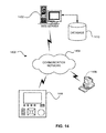
- FIG. 14 is a diagram illustrating a system 1400 for communicating image data and/or heat data according to various embodiments.
- the system 1400 comprises one or more meters 100 B in communication with a web server 1402 via a communication network 1404 .
- the system also comprises one or more user devices 1406 , which are configured to access the communication network 1404 .
- the user devices 1406 are configured as web-enabled devices and may be computer systems, laptop computers, tablets, smart phones, and/or other suitable processing systems.
- the web server 1402 comprises a database 1410 , which is configured to store image data and/or heat data.
- each meter 100 B is configured to transmit image data and/or heat data.
- the web server 1402 receives the data from the meter 100 B and processes the data accordingly.
- One service that can be provided by the web server 1402 is real-time viewing of video images obtain by the meter 100 B.
- a user of the user device 1406 may wish to view images in the vicinity of the meter 100 B.
- the web server 1402 determines that the user is authorized to access the images, via the various authentication methods described above, the web server 1402 accesses the meter 100 B and requests to receive real-time video.
- the meter 100 B transmits the video to the web server 1402 , which then provide a web page or other means, suitable for the format of the user device 1406 , showing the real-time video.
- the user of the user device 1406 may request to see images and/or video already captured. If the data corresponding to the requested images and/or video is already stored in the database 1410 , the web server 1402 can provide a web page showing the requested data. Also, the user may request to view images and/or video from multiple meters. In the case of multiple meters, the web server 1402 may provide a web page that includes multiple views arranged in a suitable manner, allowing the user to view multiple images simultaneously.
- the system 1400 shown in FIG. 14 may also be adaptable for providing alarms and/or warnings as needed. Notifications can be provided by the web server 1402 to one or more user devices 1406 as needed, based on the type of condition observed. For example, if a person in the vicinity of a meter 100 B attempts to access the meter without proper authentication, a security warning may be provided to a security system or other user device 1406 as needed. In another example, if an arc flash discharge is detected in electrical switchgear or other electrical equipment near the meter 100 B, a warning can be provided to a suitable user device 1406 to notify the user that the electrical switchgear or other electrical equipment is being shut down or that the electrical switchgear or other electrical equipment needs to be shut down.
- notification, alarm, warning, cautions, etc. can be provided by the web server 1402 . It is to be appreciated that notification, alarm, warning, cautions, etc. can be generated by the web server 1402 based on the data received from the meter 100 B or the web server may relay a notification, alarm, warning, cautions, etc. that was generated at the meter 100 B.
- the web server 1402 may detect other cautionary events, such as images, videos, changes in an image or heat, etc.
- the process of detecting events can be performed by the processing module 120 of each individual meter 100 B, by the web server 1402 , or by both.
- the web server 1402 can provide an email, link to a web page, SMS message, or other suitable communication to the user regarding the detected event.
- the communication e.g., email
- the communication may contain, for example, a video of the event.
- the video in this embodiment may have a time duration limit (e.g., about 30 seconds or a minute).
- the video may extend from a certain time (e.g., about ten seconds) before a specific action within the event to a certain time (e.g., about twenty seconds) after the specific action.
- the duration of the video and the times before and after the specific action or event can be customized by an operator of the web server 1402 or by one or more users of the user devices 1406 .
- Processing the events may be performed by the web server 1402 or by each individual meter 100 B.
- the events may be analyzed based on various mathematical processes, such as Fourier analysis, Gaussian analysis, color saturation change analysis, pixel count change analysis, or other suitable processes.
- the meter 100 B may be employed as a communication device used in conjunction with real-time viewing of the video images.
- the speaker 1104 and microphone 1106 may be used for communicating with a central office where a user may be given instructions by a remote operator on emergency situations when a problem occurs. This embodiment will enable the remote operator to view the user in the vicinity of the meter 100 B, i.e., the local user, and provide to the local user operation instructions to walk the local user through a possible remediation procedure.
- the meter 100 B may employ the microphone 1106 to detect sound in the vicinity of the meter 100 B.
- the microphone is continuously listening and at least one processor, e.g., processing module 120 , is performing signal analysis on the incoming audio or sound to determine if the incoming audio or sound has exceeded a predetermined threshold, which in certain embodiments may be adjustable. Different thresholds may be set to identify different events, e.g., one predetermined threshold may be indicative of an explosion.
- the processing module 120 is configured to trigger a tripping action to a relay or circuit breaker causing the relay or circuit breaker to shut down the power or a particular piece of equipment, for example, to thereby minimize the chance of a further explosion.
- the meter 100 B may send an alert or alarm of such an explosion to an operator according the various methods and embodiments described above.
- the processing module 120 triggers, e.g., the relay, circuit breaker, alarm, etc., upon detection of both an incoming audio signal exceeding a threshold (e.g., an explosion) and an arc flash.
- a threshold e.g., an explosion
- the detection of an explosion and detection of the arc flash must occur within a predetermined period of time for the processing module 120 to cause the trigger.
- the detection of an arc flash will cause the processing module 120 to enable the microphone 1106 to go into a listen mode.
- the detection of an arc flash will cause the processing module 120 to set a different threshold for the detection of an audio event, e.g., a higher or lower threshold than previously set.
Landscapes
- Engineering & Computer Science (AREA)
- Computer Security & Cryptography (AREA)
- Theoretical Computer Science (AREA)
- General Engineering & Computer Science (AREA)
- Physics & Mathematics (AREA)
- General Physics & Mathematics (AREA)
- Computer Hardware Design (AREA)
- Software Systems (AREA)
- Signal Processing (AREA)
- Computing Systems (AREA)
- Computer Networks & Wireless Communication (AREA)
- Multimedia (AREA)
- Power Engineering (AREA)
- Arrangements For Transmission Of Measured Signals (AREA)
Abstract
Description
Claims (31)
Priority Applications (4)
| Application Number | Priority Date | Filing Date | Title |
|---|---|---|---|
| US14/539,979 US10033970B2 (en) | 2009-08-05 | 2014-11-12 | Intelligent electronic device having image capture capabilities |
| US16/040,683 US11283795B2 (en) | 2009-08-05 | 2018-07-20 | Intelligent electronic device having image capture capabilities |
| US17/699,769 US11937022B2 (en) | 2009-08-05 | 2022-03-21 | Intelligent electronic device having user-authenticating capabilities |
| US18/583,318 US20240195944A1 (en) | 2009-08-05 | 2024-02-21 | Intelligent electronic device having user-authenticating capabilities |
Applications Claiming Priority (3)
| Application Number | Priority Date | Filing Date | Title |
|---|---|---|---|
| US12/536,035 US8665061B2 (en) | 2009-08-05 | 2009-08-05 | Intelligent electronic device having user-authenticating capabilities |
| US14/194,677 US10270764B2 (en) | 2009-08-05 | 2014-03-01 | Intelligent electronic device having user-authenticating capabilities |
| US14/539,979 US10033970B2 (en) | 2009-08-05 | 2014-11-12 | Intelligent electronic device having image capture capabilities |
Related Parent Applications (2)
| Application Number | Title | Priority Date | Filing Date |
|---|---|---|---|
| US14/194,677 Continuation-In-Part US10270764B2 (en) | 2009-08-05 | 2014-03-01 | Intelligent electronic device having user-authenticating capabilities |
| US14/194,677 Continuation US10270764B2 (en) | 2009-08-05 | 2014-03-01 | Intelligent electronic device having user-authenticating capabilities |
Related Child Applications (2)
| Application Number | Title | Priority Date | Filing Date |
|---|---|---|---|
| US16/040,683 Continuation US11283795B2 (en) | 2009-08-05 | 2018-07-20 | Intelligent electronic device having image capture capabilities |
| US16/040,683 Continuation-In-Part US11283795B2 (en) | 2009-08-05 | 2018-07-20 | Intelligent electronic device having image capture capabilities |
Publications (2)
| Publication Number | Publication Date |
|---|---|
| US20150070507A1 US20150070507A1 (en) | 2015-03-12 |
| US10033970B2 true US10033970B2 (en) | 2018-07-24 |
Family
ID=52625229
Family Applications (1)
| Application Number | Title | Priority Date | Filing Date |
|---|---|---|---|
| US14/539,979 Active US10033970B2 (en) | 2009-08-05 | 2014-11-12 | Intelligent electronic device having image capture capabilities |
Country Status (1)
| Country | Link |
|---|---|
| US (1) | US10033970B2 (en) |
Cited By (2)
| Publication number | Priority date | Publication date | Assignee | Title |
|---|---|---|---|---|
| US20180332038A1 (en) * | 2009-08-05 | 2018-11-15 | Electro Industries/Gauge Tech | Intelligent electronic device having image capture capabilities |
| US11937022B2 (en) | 2009-08-05 | 2024-03-19 | Ei Electronics Llc | Intelligent electronic device having user-authenticating capabilities |
Families Citing this family (36)
| Publication number | Priority date | Publication date | Assignee | Title |
|---|---|---|---|---|
| US9785173B2 (en) * | 2013-03-15 | 2017-10-10 | General Electric Company | Wireless communication systems and methods for intelligent electronic devices |
| EP3014822A4 (en) * | 2013-06-28 | 2017-01-04 | Schneider Electric USA, Inc. | Systems and methods of blending machine-readable and human-readable elements on a display |
| CN104767974B (en) * | 2015-04-09 | 2018-02-06 | 中水三立数据技术股份有限公司 | A kind of intelligent telemetry terminal and its control method with video monitoring function |
| WO2016170444A1 (en) * | 2015-04-21 | 2016-10-27 | 株式会社半導体エネルギー研究所 | Semiconductor device or system containing same |
| CN105608800B (en) * | 2015-12-21 | 2018-11-20 | 国网四川省电力公司电力科学研究院 | A kind of portable intelligent ammeter payment fault detection system |
| FR3050034B1 (en) * | 2016-04-12 | 2019-08-02 | Sagemcom Energy & Telecom Sas | METHOD FOR DETECTING A FAULT IN AN ELECTRIC ENERGY METER COMPRISING A CUTTING MEMBER |
| CN106443101A (en) * | 2016-08-29 | 2017-02-22 | 王月园 | Three-phase electric energy meter |
| JP6614101B2 (en) * | 2016-11-01 | 2019-12-04 | オムロン株式会社 | Electricity meter and method of identifying the electricity meter fire location |
| JP6614100B2 (en) * | 2016-11-01 | 2019-12-04 | オムロン株式会社 | Electricity meter and method of identifying the electricity meter fire location |
| JP6614166B2 (en) * | 2017-01-13 | 2019-12-04 | オムロン株式会社 | Factor determination device and electric energy management system |
| CN107134060A (en) * | 2017-05-23 | 2017-09-05 | 成都秦川物联网科技股份有限公司 | Gas meter, flow meter tamper method and tamper gas meter, flow meter based on Internet of Things |
| US10382836B2 (en) * | 2017-06-30 | 2019-08-13 | Wipro Limited | System and method for dynamically generating and rendering highlights of a video content |
| US11316865B2 (en) | 2017-08-10 | 2022-04-26 | Nuance Communications, Inc. | Ambient cooperative intelligence system and method |
| US10546655B2 (en) | 2017-08-10 | 2020-01-28 | Nuance Communications, Inc. | Automated clinical documentation system and method |
| FR3070218B1 (en) * | 2017-08-18 | 2020-09-11 | Sagemcom Energy & Telecom Sas | SYSTEM INCLUDING AN ELECTRIC METER AND A CIRCUIT BREAKER |
| EP3707499A4 (en) | 2017-11-07 | 2021-07-28 | ABB Schweiz AG | METHOD AND DEVICE FOR IMAGING ANALYSIS OF SWITCHGEAR OR THE LIKE |
| US11301985B2 (en) * | 2017-12-06 | 2022-04-12 | Advancetrex Sensor Technologies Corp | Sensing and alert system for electrical switchgear |
| CN108152633A (en) * | 2017-12-27 | 2018-06-12 | 北京安航达科技有限公司 | Non-specific devices Working state analysis control method based on current drain waveform |
| US11062013B2 (en) * | 2018-03-02 | 2021-07-13 | Bently Nevada, Llc | Two-step hardware authentication |
| US11515020B2 (en) | 2018-03-05 | 2022-11-29 | Nuance Communications, Inc. | Automated clinical documentation system and method |
| EP3762929A4 (en) | 2018-03-05 | 2022-01-12 | Nuance Communications, Inc. | SYSTEM AND PROCEDURE FOR REVIEWING AUTOMATED CLINICAL DOCUMENTATION |
| US11250382B2 (en) | 2018-03-05 | 2022-02-15 | Nuance Communications, Inc. | Automated clinical documentation system and method |
| CN108681705B (en) * | 2018-05-15 | 2022-08-23 | 国网重庆市电力公司电力科学研究院 | Metering equipment consistency judgment method and system based on pattern recognition |
| CN108919049A (en) * | 2018-05-28 | 2018-11-30 | 国家电网公司华中分部 | A kind of Guangdong power system diagnostic method based on multidimensional information |
| US11860202B2 (en) | 2018-10-23 | 2024-01-02 | Ei Electronics Llc | Devices, systems and methods for meter setup verification |
| US11043207B2 (en) | 2019-06-14 | 2021-06-22 | Nuance Communications, Inc. | System and method for array data simulation and customized acoustic modeling for ambient ASR |
| US11216480B2 (en) | 2019-06-14 | 2022-01-04 | Nuance Communications, Inc. | System and method for querying data points from graph data structures |
| US11227679B2 (en) | 2019-06-14 | 2022-01-18 | Nuance Communications, Inc. | Ambient clinical intelligence system and method |
| US11531807B2 (en) | 2019-06-28 | 2022-12-20 | Nuance Communications, Inc. | System and method for customized text macros |
| US11226357B2 (en) | 2019-09-27 | 2022-01-18 | Landis+Gyr Innovations, Inc. | Electrical arc detection for electric meter socket connections |
| US11670408B2 (en) | 2019-09-30 | 2023-06-06 | Nuance Communications, Inc. | System and method for review of automated clinical documentation |
| US11035891B1 (en) * | 2020-03-06 | 2021-06-15 | Schweitzer Engineering Laboratories, Inc. | Electric power system voltage monitoring and control with energy packets |
| EP4128306A4 (en) * | 2020-03-31 | 2023-11-29 | Abb Schweiz Ag | DEVICE AND METHOD FOR DETERMINING THE STATE OF A CIRCUIT BREAKER IN A SWITCHGEAR |
| US11222103B1 (en) | 2020-10-29 | 2022-01-11 | Nuance Communications, Inc. | Ambient cooperative intelligence system and method |
| KR102608371B1 (en) * | 2020-12-02 | 2023-12-01 | 서울대학교산학협력단 | Modular sensor platform apparatus |
| CN117784095B (en) * | 2023-12-26 | 2024-07-09 | 自然资源部国土卫星遥感应用中心 | Distributed matrix light spot detection system based on two-stage RS485 bus communication |
Citations (25)
| Publication number | Priority date | Publication date | Assignee | Title |
|---|---|---|---|---|
| US5099874A (en) * | 1990-10-26 | 1992-03-31 | Della Cave Steven F | Residential waste water disposal system |
| US5525898A (en) | 1994-12-16 | 1996-06-11 | General Electric Company | Programmable multi-channel load profile recorder and method of recording electrical energy metering quantities therein |
| US6389542B1 (en) | 1999-10-27 | 2002-05-14 | Terence T. Flyntz | Multi-level secure computer with token-based access control |
| US6480096B1 (en) | 1998-07-08 | 2002-11-12 | Motorola, Inc. | Method and apparatus for theft deterrence and secure data retrieval in a communication device |
| US20030115148A1 (en) * | 2001-12-13 | 2003-06-19 | Takhar Harinder Singh | Method and apparatus for processing a secure transaction |
| US6608911B2 (en) | 2000-12-21 | 2003-08-19 | Digimarc Corporation | Digitally watermaking holograms for use with smart cards |
| US6735497B2 (en) | 1999-09-22 | 2004-05-11 | Telepharmacy Solutions, Inc. | Systems and methods for dispensing medical products |
| US20050060110A1 (en) * | 2003-09-11 | 2005-03-17 | International Business Machines Corporation | Method, apparatus and computer program product for implementing enhanced notification and control features in oscilloscopes |
| US6912299B1 (en) * | 1998-02-18 | 2005-06-28 | Nec Corporation | Device for detecting a fingerprint, electric apparatus and doorkeeper apparatus |
| US6944700B2 (en) | 2001-06-15 | 2005-09-13 | Logitech Europe S.A. | Method and system for transferring data between a digital camera and a host |
| US7043643B1 (en) | 2001-12-06 | 2006-05-09 | Adaptec, Inc. | Method and apparatus for operating a computer in a secure mode |
| US20060178117A1 (en) * | 2004-12-03 | 2006-08-10 | Haeusermann Deutschland Gmbh | Devices for protection against overheated operating temperatures of mobile telephones |
| US7130454B1 (en) | 1998-07-20 | 2006-10-31 | Viisage Technology, Inc. | Real-time facial recognition and verification system |
| US20070055889A1 (en) * | 2002-08-29 | 2007-03-08 | Henneberry Scott M | Multi-function intelligent electronic device with secure access |
| US20070108990A1 (en) * | 2003-09-24 | 2007-05-17 | Chubu Electric Power Co., Inc. | Arc monitoring system |
| US7271996B2 (en) | 2004-12-03 | 2007-09-18 | Electro Industries/Gauge Tech | Current inputs interface for an electrical device |
| US20080104143A1 (en) * | 2006-11-01 | 2008-05-01 | Agilent Technologies, Inc. | Method and device for storing data available on the device in a database |
| US7463986B2 (en) | 2002-10-25 | 2008-12-09 | Hudson Bay Wireless Llc | Electrical power metering system |
| US20100284612A1 (en) | 2008-01-17 | 2010-11-11 | Koninklijke Philips Electronics N.V. | Flash detection |
| US20110165688A1 (en) | 2008-08-29 | 2011-07-07 | Fio Corporation | Single-use handheld diagnostic test device, and an biological and environmental test samples |
| EP2345978A1 (en) | 2010-01-14 | 2011-07-20 | Deutsche Telekom AG | Detection of flash illuminated scenes in video clips and related ranking of video clips |
| US8218086B2 (en) | 2007-12-11 | 2012-07-10 | Ericsson Television Inc. | Flash detection |
| US8442660B2 (en) | 2005-10-28 | 2013-05-14 | Electro Industries/Gauge Tech | Intelligent electronic device having audible and visual interface |
| US20130223674A1 (en) | 2012-02-27 | 2013-08-29 | L-1 Secure Credentialing, Inc. | Method and Apparatus for the Detection of Digital Watermarks for Instant Credential Authentication |
| US8665061B2 (en) | 2009-08-05 | 2014-03-04 | Electro Industries/Gauge Tech | Intelligent electronic device having user-authenticating capabilities |
-
2014
- 2014-11-12 US US14/539,979 patent/US10033970B2/en active Active
Patent Citations (25)
| Publication number | Priority date | Publication date | Assignee | Title |
|---|---|---|---|---|
| US5099874A (en) * | 1990-10-26 | 1992-03-31 | Della Cave Steven F | Residential waste water disposal system |
| US5525898A (en) | 1994-12-16 | 1996-06-11 | General Electric Company | Programmable multi-channel load profile recorder and method of recording electrical energy metering quantities therein |
| US6912299B1 (en) * | 1998-02-18 | 2005-06-28 | Nec Corporation | Device for detecting a fingerprint, electric apparatus and doorkeeper apparatus |
| US6480096B1 (en) | 1998-07-08 | 2002-11-12 | Motorola, Inc. | Method and apparatus for theft deterrence and secure data retrieval in a communication device |
| US7130454B1 (en) | 1998-07-20 | 2006-10-31 | Viisage Technology, Inc. | Real-time facial recognition and verification system |
| US6735497B2 (en) | 1999-09-22 | 2004-05-11 | Telepharmacy Solutions, Inc. | Systems and methods for dispensing medical products |
| US6389542B1 (en) | 1999-10-27 | 2002-05-14 | Terence T. Flyntz | Multi-level secure computer with token-based access control |
| US6608911B2 (en) | 2000-12-21 | 2003-08-19 | Digimarc Corporation | Digitally watermaking holograms for use with smart cards |
| US6944700B2 (en) | 2001-06-15 | 2005-09-13 | Logitech Europe S.A. | Method and system for transferring data between a digital camera and a host |
| US7043643B1 (en) | 2001-12-06 | 2006-05-09 | Adaptec, Inc. | Method and apparatus for operating a computer in a secure mode |
| US20030115148A1 (en) * | 2001-12-13 | 2003-06-19 | Takhar Harinder Singh | Method and apparatus for processing a secure transaction |
| US20070055889A1 (en) * | 2002-08-29 | 2007-03-08 | Henneberry Scott M | Multi-function intelligent electronic device with secure access |
| US7463986B2 (en) | 2002-10-25 | 2008-12-09 | Hudson Bay Wireless Llc | Electrical power metering system |
| US20050060110A1 (en) * | 2003-09-11 | 2005-03-17 | International Business Machines Corporation | Method, apparatus and computer program product for implementing enhanced notification and control features in oscilloscopes |
| US20070108990A1 (en) * | 2003-09-24 | 2007-05-17 | Chubu Electric Power Co., Inc. | Arc monitoring system |
| US7271996B2 (en) | 2004-12-03 | 2007-09-18 | Electro Industries/Gauge Tech | Current inputs interface for an electrical device |
| US20060178117A1 (en) * | 2004-12-03 | 2006-08-10 | Haeusermann Deutschland Gmbh | Devices for protection against overheated operating temperatures of mobile telephones |
| US8442660B2 (en) | 2005-10-28 | 2013-05-14 | Electro Industries/Gauge Tech | Intelligent electronic device having audible and visual interface |
| US20080104143A1 (en) * | 2006-11-01 | 2008-05-01 | Agilent Technologies, Inc. | Method and device for storing data available on the device in a database |
| US8218086B2 (en) | 2007-12-11 | 2012-07-10 | Ericsson Television Inc. | Flash detection |
| US20100284612A1 (en) | 2008-01-17 | 2010-11-11 | Koninklijke Philips Electronics N.V. | Flash detection |
| US20110165688A1 (en) | 2008-08-29 | 2011-07-07 | Fio Corporation | Single-use handheld diagnostic test device, and an biological and environmental test samples |
| US8665061B2 (en) | 2009-08-05 | 2014-03-04 | Electro Industries/Gauge Tech | Intelligent electronic device having user-authenticating capabilities |
| EP2345978A1 (en) | 2010-01-14 | 2011-07-20 | Deutsche Telekom AG | Detection of flash illuminated scenes in video clips and related ranking of video clips |
| US20130223674A1 (en) | 2012-02-27 | 2013-08-29 | L-1 Secure Credentialing, Inc. | Method and Apparatus for the Detection of Digital Watermarks for Instant Credential Authentication |
Cited By (3)
| Publication number | Priority date | Publication date | Assignee | Title |
|---|---|---|---|---|
| US20180332038A1 (en) * | 2009-08-05 | 2018-11-15 | Electro Industries/Gauge Tech | Intelligent electronic device having image capture capabilities |
| US11283795B2 (en) * | 2009-08-05 | 2022-03-22 | Electro Industries/Gauge Tech | Intelligent electronic device having image capture capabilities |
| US11937022B2 (en) | 2009-08-05 | 2024-03-19 | Ei Electronics Llc | Intelligent electronic device having user-authenticating capabilities |
Also Published As
| Publication number | Publication date |
|---|---|
| US20150070507A1 (en) | 2015-03-12 |
Similar Documents
| Publication | Publication Date | Title |
|---|---|---|
| US10033970B2 (en) | Intelligent electronic device having image capture capabilities | |
| US10270764B2 (en) | Intelligent electronic device having user-authenticating capabilities | |
| US11937022B2 (en) | Intelligent electronic device having user-authenticating capabilities | |
| US7415725B2 (en) | Multi-function intelligent electronic device with secure access | |
| KR101379223B1 (en) | Door locking system having a function of enhance a safety of operator in electric power equipments | |
| US10303860B2 (en) | Security through layers in an intelligent electronic device | |
| CN104954733B (en) | Safety nursing system capable of actively detecting position of terminal device | |
| Erol-Kantarci et al. | Smart grid forensic science: applications, challenges, and open issues | |
| KR101403465B1 (en) | Switchboard Integration Management system based mobile app. | |
| US12067090B2 (en) | Security through layers in an intelligent electronic device | |
| JP2014529983A (en) | Measuring point system and method for measuring electrical energy / power | |
| CN109742862A (en) | Safety utilization of electric power tele-control system | |
| KR101225050B1 (en) | Multi metering system for preventing electricity theft | |
| CN108107801A (en) | A kind of system and method for being used to carry out batch meter intelligent protection | |
| JP2011072121A (en) | Electrical facility measurement monitoring system, measurement monitoring device, and program | |
| US11283795B2 (en) | Intelligent electronic device having image capture capabilities | |
| CN107490711A (en) | A kind of anti-electricity-theft device and its application method | |
| KR101818124B1 (en) | Circuit Breaker Integrated Electricity Measuring Module for Monitoring the Load Electricity Condition | |
| US9779566B2 (en) | Resource management based on physical authentication and authorization | |
| CN117713362A (en) | High-pressure metering monitoring equipment | |
| KR101190244B1 (en) | Apparatus for remote controlling and heat sensing in distributing board | |
| KR101217674B1 (en) | Distributing board management system and method for managing the same | |
| CN106291016A (en) | A kind of intelligent electric meter preventing power stealing | |
| CN114091828A (en) | Transformer substation risk management and control and hidden danger troubleshooting system | |
| CN108663970A (en) | A kind of electric power operation safety monitoring system |
Legal Events
| Date | Code | Title | Description |
|---|---|---|---|
| AS | Assignment |
Owner name: ELECTRO INDUSTRIES/GAUGE TECH, NEW YORK Free format text: ASSIGNMENT OF ASSIGNORS INTEREST;ASSIGNOR:KAGAN, ERRAN;REEL/FRAME:034159/0981 Effective date: 20141029 |
|
| STCF | Information on status: patent grant |
Free format text: PATENTED CASE |
|
| MAFP | Maintenance fee payment |
Free format text: PAYMENT OF MAINTENANCE FEE, 4TH YR, SMALL ENTITY (ORIGINAL EVENT CODE: M2551); ENTITY STATUS OF PATENT OWNER: SMALL ENTITY Year of fee payment: 4 |
|
| AS | Assignment |
Owner name: EI ELECTRONICS LLC D/B/A ELECTRO INDUSTRIES/GAUGE TECH, NEW YORK Free format text: ASSIGNMENT OF ASSIGNORS INTEREST;ASSIGNOR:E.I. ELECTRONICS, INC. FORMERLY DOING BUSINESS AS ELECTRO INDUSTRIES/GAUGE TECH;REEL/FRAME:063011/0269 Effective date: 20230309 Owner name: EI ELECTRONICS LLC D/B/A ELECTRO INDUSTRIES/GAUGE TECH, NEW YORK Free format text: ASSIGNMENT OF ASSIGNOR'S INTEREST;ASSIGNOR:E.I. ELECTRONICS, INC. FORMERLY DOING BUSINESS AS ELECTRO INDUSTRIES/GAUGE TECH;REEL/FRAME:063011/0269 Effective date: 20230309 |
|
| FEPP | Fee payment procedure |
Free format text: ENTITY STATUS SET TO UNDISCOUNTED (ORIGINAL EVENT CODE: BIG.); ENTITY STATUS OF PATENT OWNER: LARGE ENTITY |
|
| MAFP | Maintenance fee payment |
Free format text: PAYMENT OF MAINTENANCE FEE, 8TH YEAR, LARGE ENTITY (ORIGINAL EVENT CODE: M1552); ENTITY STATUS OF PATENT OWNER: LARGE ENTITY Year of fee payment: 8 |