TWI803729B - Optical imaging lens - Google Patents
Optical imaging lens Download PDFInfo
- Publication number
- TWI803729B TWI803729B TW109100882A TW109100882A TWI803729B TW I803729 B TWI803729 B TW I803729B TW 109100882 A TW109100882 A TW 109100882A TW 109100882 A TW109100882 A TW 109100882A TW I803729 B TWI803729 B TW I803729B
- Authority
- TW
- Taiwan
- Prior art keywords
- lens
- optical axis
- optical
- optical imaging
- thickness
- Prior art date
Links
Images


Classifications
-
- G—PHYSICS
- G02—OPTICS
- G02B—OPTICAL ELEMENTS, SYSTEMS OR APPARATUS
- G02B13/00—Optical objectives specially designed for the purposes specified below
- G02B13/001—Miniaturised objectives for electronic devices, e.g. portable telephones, webcams, PDAs, small digital cameras
- G02B13/0015—Miniaturised objectives for electronic devices, e.g. portable telephones, webcams, PDAs, small digital cameras characterised by the lens design
- G02B13/002—Miniaturised objectives for electronic devices, e.g. portable telephones, webcams, PDAs, small digital cameras characterised by the lens design having at least one aspherical surface
- G02B13/0045—Miniaturised objectives for electronic devices, e.g. portable telephones, webcams, PDAs, small digital cameras characterised by the lens design having at least one aspherical surface having five or more lenses
-
- G—PHYSICS
- G02—OPTICS
- G02B—OPTICAL ELEMENTS, SYSTEMS OR APPARATUS
- G02B27/00—Optical systems or apparatus not provided for by any of the groups G02B1/00 - G02B26/00, G02B30/00
- G02B27/0025—Optical systems or apparatus not provided for by any of the groups G02B1/00 - G02B26/00, G02B30/00 for optical correction, e.g. distorsion, aberration
-
- G—PHYSICS
- G02—OPTICS
- G02B—OPTICAL ELEMENTS, SYSTEMS OR APPARATUS
- G02B9/00—Optical objectives characterised both by the number of the components and their arrangements according to their sign, i.e. + or -
- G02B9/64—Optical objectives characterised both by the number of the components and their arrangements according to their sign, i.e. + or - having more than six components
-
- H—ELECTRICITY
- H04—ELECTRIC COMMUNICATION TECHNIQUE
- H04N—PICTORIAL COMMUNICATION, e.g. TELEVISION
- H04N23/00—Cameras or camera modules comprising electronic image sensors; Control thereof
- H04N23/50—Constructional details
- H04N23/55—Optical parts specially adapted for electronic image sensors; Mounting thereof
Landscapes
- Physics & Mathematics (AREA)
- General Physics & Mathematics (AREA)
- Optics & Photonics (AREA)
- Engineering & Computer Science (AREA)
- Multimedia (AREA)
- Signal Processing (AREA)
- Lenses (AREA)
- Glass Compositions (AREA)
- Aiming, Guidance, Guns With A Light Source, Armor, Camouflage, And Targets (AREA)
- Lens Barrels (AREA)
Abstract
Description
本發明涉及一種光學成像鏡頭,尤指一種可用於拍攝影像及錄影的光學成像鏡頭。The invention relates to an optical imaging lens, in particular to an optical imaging lens which can be used for shooting images and recording videos.
近年來,光學成像鏡頭不斷演進,所要應用的範圍更為廣泛,除了要求鏡頭輕薄短小以外,小的光圈值(Fno)的設計有利於增進光通量,大的視場角也逐漸成為趨勢;另外,為了提高畫素與解析度,則必須增加鏡頭的像高,藉由採用更大的影像感測器來接受成像光線以滿足高畫素需求。In recent years, the optical imaging lens has been continuously evolving, and the scope of application is wider. In addition to requiring the lens to be thin and short, the design of a small aperture value (Fno) is conducive to increasing the luminous flux, and a large field of view has gradually become a trend; In addition, In order to increase the pixel and resolution, the image height of the lens must be increased, and a larger image sensor is used to receive imaging light to meet the high pixel requirements.
因此如何設計出兼具輕薄短小及具有小光圈值、大視場角與大像高且成像品質佳的光學成像鏡頭成為須挑戰並解決的問題。Therefore, how to design an optical imaging lens that is thin, light and small, has a small aperture value, a large field of view, a large image height, and good imaging quality has become a challenge and a problem to be solved.
有鑑於上述之問題,光學成像鏡頭除了達到更高畫素與成像品質良好之外,增大光圈、視場角與像高,都是本發明的改善重點。In view of the above problems, the optical imaging lens not only achieves higher pixels and better imaging quality, but also increases the aperture, field of view and image height, which are the focus of improvement of the present invention.
本發明提供一種光學成像鏡頭,主要用於拍攝影像及錄影,並應用於可攜式電子產品,例如:手機、相機、平板電腦、個人數位助理(Personal Digital Assistant, PDA)。透過透鏡的表面凹凸配置與光學參數的設計,達到縮短光學成像鏡頭系統長度、增大光圈、視場角與像高、提升成像品質,或組裝良率提升的效果。The invention provides an optical imaging lens, which is mainly used for taking images and recording videos, and is applied to portable electronic products, such as mobile phones, cameras, tablet computers, and Personal Digital Assistants (PDA). Through the concave-convex configuration of the lens surface and the design of optical parameters, the effects of shortening the length of the optical imaging lens system, increasing the aperture, field of view and image height, improving the imaging quality, or improving the assembly yield can be achieved.
在本發明說明書揭示內容中,使用以下表格列出的參數,但不侷限於只使用這些參數:
依據本發明一實施例所提供的光學成像鏡頭,該光學成像鏡頭從一物側至一像側沿一光軸依序包括一第一透鏡、一第二透鏡、一第三透鏡、一第四透鏡、一第五透鏡、一第六透鏡、一第七透鏡以及一第八透鏡,該第一透鏡至該第八透鏡各自具有一朝向該物側且使成像光線通過的物側面以及一朝向該像側且使成像光線通過的像側面,其中:該第二透鏡具有負屈光率;該第四透鏡的該像側面的一圓周區域為凸面;該第五透鏡具有負屈光率;該第五透鏡的該像側面的一圓周區域為凸面;該第六透鏡的該物側面的一光軸區域為凹面;該第七透鏡具有負屈光率;該光學成像鏡頭具有屈光率的透鏡只有上述八片。According to an optical imaging lens provided by an embodiment of the present invention, the optical imaging lens includes a first lens, a second lens, a third lens, and a fourth lens in sequence along an optical axis from an object side to an image side. lens, a fifth lens, a sixth lens, a seventh lens, and an eighth lens, each of the first lens to the eighth lens has an object side facing the object side and allowing the imaging light to pass through and an object side facing the object side. The image side and the image side through which the imaging light passes, wherein: the second lens has a negative refractive power; a peripheral area of the image side of the fourth lens is a convex surface; the fifth lens has a negative refractive power; A circumferential area of the image side of the five lenses is a convex surface; an optical axis area of the object side of the sixth lens is concave; the seventh lens has a negative refractive power; the optical imaging lens has only a lens with a refractive power The above eight slices.
依據本發明另一實施例所提供的光學成像鏡頭,該光學成像鏡頭從一物側至一像側沿一光軸依序包括一第一透鏡、一第二透鏡、一第三透鏡、一第四透鏡、一第五透鏡、一第六透鏡、一第七透鏡以及一第八透鏡,該第一透鏡至該第八透鏡各自具有一朝向該物側且使成像光線通過的物側面以及一朝向該像側且使成像光線通過的像側面,其中:該第二透鏡具有負屈光率;該第三透鏡的該物側面的一圓周區域為凹面;該第四透鏡的該像側面的一圓周區域為凸面;該第五透鏡具有負屈光率;該第五透鏡的該像側面的一圓周區域為凸面;該第六透鏡的該物側面的一光軸區域為凹面;該光學成像鏡頭具有屈光率的透鏡只有上述八片,且該光學成像鏡頭滿足條件式(1):TTL/ImgH≦1.500。According to the optical imaging lens provided in another embodiment of the present invention, the optical imaging lens sequentially includes a first lens, a second lens, a third lens, and a first lens along an optical axis from an object side to an image side. Four lenses, a fifth lens, a sixth lens, a seventh lens, and an eighth lens, each of the first lens to the eighth lens has an object side facing the object side and allowing the imaging light to pass through, and a direction toward the object side. The image side and the image side through which imaging light rays pass, wherein: the second lens has a negative refractive power; a circumferential area of the object side of the third lens is concave; a circumference of the image side of the fourth lens The region is convex; the fifth lens has a negative refractive power; a peripheral region of the image side of the fifth lens is convex; an optical axis region of the object side of the sixth lens is concave; the optical imaging lens has There are only the above eight lenses with diopter power, and the optical imaging lens satisfies the conditional formula (1): TTL/ImgH≦1.500.
依據本發明另一實施例所提供的光學成像鏡頭,該光學成像鏡頭從一物側至一像側沿一光軸依序包括一第一透鏡、一第二透鏡、一第三透鏡、一第四透鏡、一第五透鏡、一第六透鏡、一第七透鏡以及一第八透鏡,該第一透鏡至該第八透鏡各自具有一朝向該物側且使成像光線通過的物側面以及一朝向該像側且使成像光線通過的像側面,其中:該第一透鏡的該像側面的一光軸區域為凹面;該第二透鏡具有負屈光率;該第三透鏡的該物側面的一圓周區域為凹面;該第四透鏡的該像側面的一圓周區域為凸面;該第五透鏡的該物側面的一圓周區域為凹面;該第五透鏡的該像側面的一圓周區域為凸面;該第六透鏡的該物側面的一光軸區域為凹面;該第七透鏡具有負屈光率;該光學成像鏡頭具有屈光率的透鏡只有上述八片。According to the optical imaging lens provided in another embodiment of the present invention, the optical imaging lens sequentially includes a first lens, a second lens, a third lens, and a first lens along an optical axis from an object side to an image side. Four lenses, a fifth lens, a sixth lens, a seventh lens, and an eighth lens, each of the first lens to the eighth lens has an object side facing the object side and allowing the imaging light to pass through, and a direction toward the object side. The image side and the image side through which the imaging light passes, wherein: an optical axis region of the image side of the first lens is concave; the second lens has a negative refractive power; an object side of the third lens The circumferential area is concave; a circumferential area of the image side of the fourth lens is convex; a circumferential area of the object side of the fifth lens is concave; a circumferential area of the image side of the fifth lens is convex; An optical axis area of the object side of the sixth lens is concave; the seventh lens has a negative refractive power; the optical imaging lens has only the above eight lenses with a refractive power.
上述光學成像鏡頭還可進一步選擇地滿足以下條件式: 條件式(2):V1+V2+V4+V6+V7≦230.000; 條件式(3):(ALT+EFL)/AAG≦4.800; 條件式(4):ALT/(G56+G78)≦3.500; 條件式(5):TL/(T6+G67)≦10.000; 條件式(6):(T1+T6+G78)/(BFL+T7)≧1.000; 條件式(7):(T1+G12+T2)/BFL≧1.400; 條件式(8):AAG/(G34+T4+G45)≧2.600; 條件式(9):AAG/T6≦3.100; 條件式(10):(T4+T8)/(G12+T2)≦2.500; 條件式(11):(T2+T4+T6)/(G23+T3)≧1.400; 條件式(12):EFL/(T5+T8)≧5.000; 條件式(13):(TL+BFL)/(T4+T7)≧7.300; 條件式(14):ALT/(T6+G78)≦3.400; 條件式(15):AAG/(T1+T7+T8)≧1.000; 條件式(16):(T3+T4+T5)/(T2+BFL)≧1.000; 條件式(17):(G67+G78)/(G12+G23)≧1.600; 條件式(18):(G23+G34+G45+G56)/G78≦2.400; 條件式(19):(T1+T3+T5)/(G67+G78)≦2.400。The above-mentioned optical imaging lens can further optionally satisfy the following conditional formula: Conditional formula (2): V1+V2+V4+V6+V7≦230.000; Conditional formula (3): (ALT+EFL)/AAG≦4.800; Conditional formula (4): ALT/(G56+G78)≦3.500; Conditional formula (5): TL/(T6+G67)≦10.000; Conditional formula (6): (T1+T6+G78)/(BFL+T7)≧1.000; Conditional formula (7): (T1+G12+T2)/BFL≧1.400; Conditional formula (8): AAG/(G34+T4+G45)≧2.600; Conditional formula (9): AAG/T6≦3.100; Conditional formula (10): (T4+T8)/(G12+T2)≦2.500; Conditional formula (11): (T2+T4+T6)/(G23+T3)≧1.400; Conditional formula (12): EFL/(T5+T8)≧5.000; Conditional formula (13): (TL+BFL)/(T4+T7)≧7.300; Conditional formula (14): ALT/(T6+G78)≦3.400; Conditional formula (15): AAG/(T1+T7+T8)≧1.000; Conditional formula (16): (T3+T4+T5)/(T2+BFL)≧1.000; Conditional formula (17): (G67+G78)/(G12+G23)≧1.600; Conditional formula (18): (G23+G34+G45+G56)/G78≦2.400; Conditional formula (19): (T1+T3+T5)/(G67+G78)≦2.400.
前述所列之示例性限定關係式,亦可任意選擇性地合併不等數量施用於本發明之實施態樣中,並不限於此。在實施本發明時,除了前述關係式之外,亦可針對單一透鏡或廣泛性地針對多個透鏡額外設計出其他更多的透鏡的凹凸曲面排列等細部結構,以加強對系統性能及/或解析度的控制。須注意的是,此些細節需在無衝突之情況之下,選擇性地合併施用於本發明之其他實施例當中。The exemplary limiting relational expressions listed above can also be arbitrarily and selectively combined and applied in different quantities in the implementation of the present invention, and are not limited thereto. When implementing the present invention, in addition to the aforesaid relational expressions, other detailed structures such as the concave-convex surface arrangement of more lenses can be additionally designed for a single lens or broadly for multiple lenses, so as to enhance the system performance and/or Resolution control. It should be noted that these details should be selectively combined and applied to other embodiments of the present invention under the condition of no conflict.
由上述中可以得知,本發明之光學成像鏡頭透過控制透鏡的凹凸曲面排列,可維持其成像品質,且縮短光學成像鏡頭系統長度、增大光圈、擴大視場角、增加像高、提升成像品質。From the above, it can be known that the optical imaging lens of the present invention can maintain its imaging quality by controlling the arrangement of concave and convex curved surfaces of the lens, and shorten the length of the optical imaging lens system, increase the aperture, expand the field of view, increase the image height, and improve imaging quality.
本說明書和申請專利範圍中使用的用語「光軸區域」、「圓周區域」、「凹面」和「凸面」應基於本說明書中列出的定義來解釋。The terms "optical axis area", "circumferential area", "concave" and "convex" used in this specification and claims should be interpreted based on the definitions listed in this specification.
本說明書之光學系統包含至少一透鏡,接收入射光學系統之平行於光軸至相對光軸呈半視角(HFOV)角度內的成像光線。成像光線通過光學系統於成像面上成像。所言之「一透鏡具有正屈光率(或負屈光率)」,是指所述透鏡以高斯光學理論計算出來之近軸屈光率為正(或為負)。所言之「透鏡之物側面(或像側面)」定義為成像光線通過透鏡表面的特定範圍。成像光線包括至少兩類光線:主光線(chief ray)Lc及邊緣光線(marginal ray)Lm(如圖1所示)。透鏡之物側面(或像側面)可依不同位置區分為不同區域,包含光軸區域、圓周區域、或在部分實施例中的一個或多個中繼區域,該些區域的說明將於下方詳細闡述。The optical system in this specification includes at least one lens, which receives the imaging light from the incident optical system parallel to the optical axis to within an angle of half field of view (HFOV) relative to the optical axis. The imaging light is imaged on the imaging plane through the optical system. The term "a lens has a positive refractive power (or negative refractive power)" means that the paraxial refractive power of the lens calculated by Gaussian optics theory is positive (or negative). The so-called "object side (or image side) of the lens" is defined as a specific range where imaging light passes through the lens surface. The imaging light includes at least two types of light: chief ray (chief ray) Lc and marginal ray (marginal ray) Lm (as shown in FIG. 1 ). The object side (or image side) of the lens can be divided into different areas according to different positions, including the optical axis area, the circumference area, or one or more relay areas in some embodiments, and the description of these areas will be described in detail below. elaborate.
圖1為透鏡100的徑向剖視圖。定義透鏡100表面上的二參考點:中心點及轉換點。透鏡表面的中心點為該表面與光軸I的一交點。如圖1所例示,第一中心點CP1位於透鏡100的物側面110,第二中心點CP2位於透鏡100的像側面120。轉換點是位於透鏡表面上的一點,且該點的切線與光軸I垂直。定義透鏡表面之光學邊界OB為通過該透鏡表面徑向最外側的邊緣光線Lm與該透鏡表面相交的一點。所有的轉換點皆位於光軸I與透鏡表面之光學邊界OB之間。除此之外,若單一透鏡表面有複數個轉換點,則該些轉換點由徑向向外的方向依序自第一轉換點開始命名。例如,第一轉換點TP1(最靠近光軸I)、第二轉換點TP2(如圖4所示)及第N轉換點(距離光軸I最遠)。FIG. 1 is a radial cross-sectional view of a
定義從中心點至第一轉換點TP1的範圍為光軸區域,其中,該光軸區域包含中心點。定義距離光軸I最遠的第N轉換點徑向向外至光學邊界OB的區域為圓周區域。在部分實施例中,可另包含介於光軸區域與圓周區域之間的中繼區域,中繼區域的數量取決於轉換點的數量。The range from the central point to the first transition point TP1 is defined as the optical axis area, wherein the optical axis area includes the central point. The area from the Nth conversion point farthest from the optical axis I radially outward to the optical boundary OB is defined as the circumferential area. In some embodiments, a relay area between the optical axis area and the circumference area may be further included, and the number of the relay area depends on the number of conversion points.
當平行光軸I之光線通過一區域後,若光線朝光軸I偏折且與光軸I的交點位在透鏡像側A2,則該區域為凸面。當平行光軸I之光線通過一區域後,若光線的延伸線與光軸I的交點位在透鏡物側A1,則該區域為凹面。When the light parallel to the optical axis I passes through a region, if the light is deflected toward the optical axis I and the intersection with the optical axis I is on the image side A2 of the lens, then the region is a convex surface. After the light rays parallel to the optical axis I pass through a region, if the intersection of the extension line of the light rays and the optical axis I is on the object side A1 of the lens, the region is a concave surface.
除此之外,參見圖1,透鏡100還可包含一由光學邊界OB徑向向外延伸的組裝部130。組裝部130一般來說用以供該透鏡100組裝於光學系統之一相對應元件(圖未示)。成像光線並不會到達該組裝部130。組裝部130之結構與形狀僅為說明本發明之示例,不以此限制本發明的範圍。下列討論之透鏡的組裝部130可能會在圖式中被部分或全部省略。In addition, referring to FIG. 1 , the
參見圖2,定義中心點CP與第一轉換點TP1之間為光軸區域Z1。定義第一轉換點TP1與透鏡表面的光學邊界OB之間為圓周區域Z2。如圖2所示,平行光線211在通過光軸區域Z1後與光軸I在透鏡200的像側A2相交,即平行光線211通過光軸區域Z1的焦點位於透鏡200像側A2的R點。由於光線與光軸I相交於透鏡200像側A2,故光軸區域Z1為凸面。反之,平行光線212在通過圓周區域Z2後發散。如圖2所示,平行光線212通過圓周區域Z2後的延伸線EL與光軸I在透鏡200的物側A1相交,即平行光線212通過圓周區域Z2的焦點位於透鏡200物側A1的M點。由於光線的延伸線EL與光軸I相交於透鏡200物側A1,故圓周區域Z2為凹面。於圖2所示的透鏡200中,第一轉換點TP1是光軸區域與圓周區域的分界,即第一轉換點TP1為凸面轉凹面的分界點。Referring to FIG. 2 , the optical axis zone Z1 is defined between the central point CP and the first transition point TP1 . A circumferential zone Z2 is defined between the first transition point TP1 and the optical boundary OB of the lens surface. As shown in FIG. 2 , the
另一方面,光軸區域的面形凹凸判斷還可依該領域中通常知識者的判斷方式,即藉由近軸的曲率半徑(簡寫為R值)的正負號來判斷透鏡之光軸區域面形的凹凸。R值可常見被使用於光學設計軟體中,例如Zemax或CodeV。R值亦常見於光學設計軟體的透鏡資料表(lens data sheet)中。以物側面來說,當R值為正時,判定為物側面的光軸區域為凸面;當R值為負時,判定物側面的光軸區域為凹面。反之,以像側面來說,當R值為正時,判定像側面的光軸區域為凹面;當R值為負時,判定像側面的光軸區域為凸面。此方法判定的結果與前述藉由光線/光線延伸線與光軸的交點判定方式的結果一致,光線/光線延伸線與光軸交點的判定方式即為以一平行光軸之光線的焦點位於透鏡之物側或像側來判斷面形凹凸。本說明書所描述之「一區域為凸面(或凹面)」、「一區域為凸(或凹)」或「一凸面(或凹面)區域」可被替換使用。On the other hand, the judgment of the concave-convex surface shape of the optical axis area can also be judged by the common knowledge in this field, that is, the optical axis area surface of the lens can be judged by the sign of the paraxial curvature radius (abbreviated as R value). shaped bumps. R-values are commonly used in optical design software such as Zemax or CodeV. The R-value is also commonly found in the lens data sheet of optical design software. For the object side, when the R value is positive, it is judged that the optical axis area on the object side is convex; when the R value is negative, it is judged that the optical axis area on the object side is concave. Conversely, for the image side, when the R value is positive, the optical axis area on the image side is judged to be concave; when the R value is negative, the optical axis area on the image side is judged to be convex. The judgment result of this method is consistent with the above-mentioned result of judging the intersection point of the ray/ray extension line and the optical axis. The judgment method of the intersection point of the ray/ray extension line and the optical axis is that the focal point of a ray parallel to the optical axis is located on the lens Use the object side or the image side to judge the unevenness of the surface. "A region is convex (or concave)", "a region is convex (or concave)" or "a convex (or concave) region" described in this specification can be used interchangeably.
圖3至圖5提供了在各個情況下判斷透鏡區域的面形及區域分界的範例,包含前述之光軸區域、圓周區域及中繼區域。3 to 5 provide examples of judging the surface shape and area boundary of the lens area in each case, including the aforementioned optical axis area, circumference area, and relay area.
圖3為透鏡300的徑向剖視圖。參見圖3,透鏡300的像側面320在光學邊界OB內僅存在一個轉換點TP1。透鏡300的像側面320的光軸區域Z1及圓周區域Z2如圖3所示。此像側面320的R值為正(即R>0),因此,光軸區域Z1為凹面。FIG. 3 is a radial cross-sectional view of the
一般來說,以轉換點為界的各個區域面形會與相鄰的區域面形相反,因此,可用轉換點來界定面形的轉變,即自轉換點由凹面轉凸面或由凸面轉凹面。於圖3中,由於光軸區域Z1為凹面,面形於轉換點TP1轉變,故圓周區域Z2為凸面。Generally speaking, the surface shape of each area bounded by the conversion point will be opposite to that of the adjacent area. Therefore, the conversion point can be used to define the transformation of the surface shape, that is, from the conversion point to the concave surface to the convex surface or from the convex surface to the concave surface. In FIG. 3 , since the optical axis zone Z1 is a concave surface, and the surface shape changes at the transition point TP1 , the peripheral zone Z2 is a convex surface.
圖4為透鏡400的徑向剖視圖。參見圖4,透鏡400的物側面410存在一第一轉換點TP1及一第二轉換點TP2。定義光軸I與第一轉換點TP1之間為物側面410的光軸區域Z1。此物側面410的R值為正(即R>0),因此,光軸區域Z1為凸面。FIG. 4 is a radial cross-sectional view of the
定義第二轉換點TP2與透鏡400的物側面410的光學邊界OB之間為圓周區域Z2,該物側面410的該圓周區域Z2亦為凸面。除此之外,定義第一轉換點TP1與第二轉換點TP2之間為中繼區域Z3,該物側面410的該中繼區域Z3為凹面。再次參見圖4,物側面410由光軸I徑向向外依序包含光軸I與第一轉換點TP1之間的光軸區域Z1、位於第一轉換點TP1與第二轉換點TP2之間的中繼區域Z3,及第二轉換點TP2與透鏡400的物側面410的光學邊界OB之間的圓周區域Z2。由於光軸區域Z1為凸面,面形自第一轉換點TP1轉變為凹,故中繼區域Z3為凹面,又面形自第二轉換點TP2再轉變為凸,故圓周區域Z2為凸面。A circumferential area Z2 is defined between the second transition point TP2 and the optical boundary OB of the
圖5為透鏡500的徑向剖視圖。透鏡500的物側面510無轉換點。對於無轉換點的透鏡表面,例如透鏡500的物側面510,定義自光軸I起算至透鏡表面光學邊界OB之間距離的0~50%為光軸區域,自光軸I起算至透鏡表面光學邊界OB之間距離的50~100%為圓周區域。參見圖5所示之透鏡500,定義光軸I至自光軸I起算到透鏡500表面光學邊界OB之間距離的50%為物側面510的光軸區域Z1。此物側面510的R值為正(即R>0),因此,光軸區域Z1為凸面。由於透鏡500的物側面510無轉換點,因此物側面510的圓周區域Z2亦為凸面。透鏡500更可具有組裝部(圖未示)自圓周區域Z2徑向向外延伸。FIG. 5 is a radial cross-sectional view of the
依據本發明一實施例所提供的光學成像鏡頭,該光學成像鏡頭從一物側至一像側沿一光軸依序包括一第一透鏡、一第二透鏡、一第三透鏡、一第四透鏡、一第五透鏡、一第六透鏡、一第七透鏡以及一第八透鏡,該第一透鏡至該第八透鏡各自具有一朝向該物側且使成像光線通過的物側面以及一朝向該像側且使成像光線通過的像側面,其中:該第二透鏡具有負屈光率;該第四透鏡的該像側面的一圓周區域為凸面;該第五透鏡具有負屈光率;該第五透鏡的該像側面的一圓周區域為凸面;該第六透鏡的該物側面的一光軸區域為凹面;該第七透鏡具有負屈光率;該光學成像鏡頭具有屈光率的透鏡只有上述八片。藉此,本實施例能有效使整個光學透鏡系統在增大光通量、擴大視場角的同時具有良好的成像品質。According to an optical imaging lens provided by an embodiment of the present invention, the optical imaging lens includes a first lens, a second lens, a third lens, and a fourth lens in sequence along an optical axis from an object side to an image side. lens, a fifth lens, a sixth lens, a seventh lens, and an eighth lens, each of the first lens to the eighth lens has an object side facing the object side and allowing the imaging light to pass through and an object side facing the object side. The image side and the image side through which the imaging light passes, wherein: the second lens has a negative refractive power; a peripheral area of the image side of the fourth lens is a convex surface; the fifth lens has a negative refractive power; A circumferential area of the image side of the five lenses is a convex surface; an optical axis area of the object side of the sixth lens is concave; the seventh lens has a negative refractive power; the optical imaging lens has only a lens with a refractive power The above eight slices. Therefore, this embodiment can effectively make the entire optical lens system have good imaging quality while increasing the luminous flux and expanding the viewing angle.
依據本發明另一實施例所提供的光學成像鏡頭,該光學成像鏡頭從一物側至一像側沿一光軸依序包括一第一透鏡、一第二透鏡、一第三透鏡、一第四透鏡、一第五透鏡、一第六透鏡、一第七透鏡以及一第八透鏡,該第一透鏡至該第八透鏡各自具有一朝向該物側且使成像光線通過的物側面以及一朝向該像側且使成像光線通過的像側面,其中:該第二透鏡具有負屈光率;該第三透鏡的該物側面的一圓周區域為凹面;該第四透鏡的該像側面的一圓周區域為凸面;該第五透鏡具有負屈光率;該第五透鏡的該像側面的一圓周區域為凸面;該第六透鏡的該物側面的一光軸區域為凹面;該光學成像鏡頭具有屈光率的透鏡只有上述八片,且該光學成像鏡頭滿足條件式(1):TTL/ImgH≦1.500。藉此,本實施例能有效縮短光學成像鏡頭的系統長度,並使光學成像鏡頭能有較大的像高,使影像感測器可接收到較多的光線,以適當地增加光學成像品質,其中,TTL/ImgH較佳的實施範圍為1.000≦TTL/ImgH≦1.500。According to the optical imaging lens provided in another embodiment of the present invention, the optical imaging lens sequentially includes a first lens, a second lens, a third lens, and a first lens along an optical axis from an object side to an image side. Four lenses, a fifth lens, a sixth lens, a seventh lens, and an eighth lens, each of the first lens to the eighth lens has an object side facing the object side and allowing the imaging light to pass through, and a direction toward the object side. The image side and the image side through which imaging light rays pass, wherein: the second lens has a negative refractive power; a circumferential area of the object side of the third lens is concave; a circumference of the image side of the fourth lens The region is convex; the fifth lens has a negative refractive power; a peripheral region of the image side of the fifth lens is convex; an optical axis region of the object side of the sixth lens is concave; the optical imaging lens has There are only the above eight lenses with diopter power, and the optical imaging lens satisfies the conditional formula (1): TTL/ImgH≦1.500. Thereby, this embodiment can effectively shorten the system length of the optical imaging lens, and enable the optical imaging lens to have a larger image height, so that the image sensor can receive more light, so as to appropriately increase the optical imaging quality, Wherein, the preferred implementation range of TTL/ImgH is 1.000≦TTL/ImgH≦1.500.
依據本發明另一實施例所提供的光學成像鏡頭,該光學成像鏡頭從一物側至一像側沿一光軸依序包括一第一透鏡、一第二透鏡、一第三透鏡、一第四透鏡、一第五透鏡、一第六透鏡、一第七透鏡以及一第八透鏡,該第一透鏡至該第八透鏡各自具有一朝向該物側且使成像光線通過的物側面以及一朝向該像側且使成像光線通過的像側面,其中:該第一透鏡的該像側面的一光軸區域為凹面;該第二透鏡具有負屈光率;該第三透鏡的該物側面的一圓周區域為凹面;該第四透鏡的該像側面的一圓周區域為凸面;該第五透鏡的該物側面的一圓周區域為凹面;該第五透鏡的該像側面的一圓周區域為凸面;該第六透鏡的該物側面的一光軸區域為凹面;該第七透鏡具有負屈光率;該光學成像鏡頭具有屈光率的透鏡只有上述八片。藉此,本實施例可達到修正光學系統像差與降低畸變的目的。According to the optical imaging lens provided in another embodiment of the present invention, the optical imaging lens sequentially includes a first lens, a second lens, a third lens, and a first lens along an optical axis from an object side to an image side. Four lenses, a fifth lens, a sixth lens, a seventh lens, and an eighth lens, each of the first lens to the eighth lens has an object side facing the object side and allowing the imaging light to pass through, and a direction toward the object side. The image side and the image side through which the imaging light passes, wherein: an optical axis region of the image side of the first lens is concave; the second lens has a negative refractive power; an object side of the third lens The circumferential area is concave; a circumferential area of the image side of the fourth lens is convex; a circumferential area of the object side of the fifth lens is concave; a circumferential area of the image side of the fifth lens is convex; An optical axis area of the object side of the sixth lens is concave; the seventh lens has a negative refractive power; the optical imaging lens has only the above eight lenses with a refractive power. In this way, this embodiment can achieve the purpose of correcting the aberration of the optical system and reducing the distortion.
本發明的光學成像鏡頭透過適當的材料配置,當符合條件式(2):V1+V2+V4+V6+V7≦230.000時能有效改善色差,而較佳的範圍為165.000≦V1+V2+V4+V6+V7≦230.000。The optical imaging lens of the present invention can effectively improve the chromatic aberration when the conditional formula (2) is met: V1+V2+V4+V6+V7≦230.000, and the preferred range is 165.000≦V1+V2+V4 +V6+V7≦230.000.
為了達成縮短透鏡系統長度及確保成像品質,同時考量製作的難易程度,將透鏡間的空氣間隙縮小或是透鏡厚度適度的縮短作為手段,若滿足以下條件式之數值限定,能使本發明的實施例有較佳的配置: 條件式(3):(ALT+EFL)/AAG≦4.800,較佳的限制為2.800≦(ALT+EFL)/AAG≦4.800; 條件式(4):ALT/(G56+G78)≦3.500,較佳的限制為2.200≦ALT/(G56+G78)≦3.500; 條件式(5):TL/(T6+G67)≦10.000,較佳的限制為3.300≦TL/(T6+G67)≦10.000; 條件式(6):(T1+T6+G78)/(BFL+T7)≧1.000,較佳的限制為1.000≦(T1+T6+G78)/(BFL+T7)≦3.000; 條件式(7):(T1+G12+T2)/BFL≧1.400,較佳的限制為1.400≦(T1+G12+T2)/BFL≦2.300; 條件式(8):AAG/(G34+T4+G45)≧2.600,較佳的限制為2.600≦AAG/(G34+T4+G45)≦3.500; 條件式(9):AAG/T6≦3.100,較佳的限制為1.700≦AAG/T6≦3.100; 條件式(10):(T4+T8)/(G12+T2)≦2.500,較佳的限制為0.800≦(T4+T8)/(G12+T2)≦2.500; 條件式(11):(T2+T4+T6)/(G23+T3)≧1.400,較佳的限制為1.400≦(T2+T4+T6)/(G23+T3)≦2.400; 條件式(12):EFL/(T5+T8)≧5.000,較佳的限制為5.000≦EFL/(T5+T8)≦12.000; 條件式(13):(TL+BFL)/(T4+T7)≧7.300,較佳的限制為7.300≦(TL+BFL)/(T4+T7)≦13.500; 條件式(14):ALT/(T6+G78)≦3.400,較佳的限制為1.700≦ALT/(T6+G78)≦3.400; 條件式(15):AAG/(T1+T7+T8)≧1.000,較佳的限制為1.000≦AAG/(T1+T7+T8)≦3.000; 條件式(16):(T3+T4+T5)/(T2+BFL)≧1.000,較佳的限制為1.000≦(T3+T4+T5)/(T2+BFL)≦1.900; 條件式(17):(G67+G78)/(G12+G23)≧1.600,較佳的限制為1.600≦(G67+G78)/(G12+G23)≦5.200; 條件式(18):(G23+G34+G45+G56)/G78≦2.400,較佳的限制為0.500≦(G23+G34+G45+G56)/G78≦2.400; 條件式(19):(T1+T3+T5)/(G67+G78)≦2.400,較佳的限制為0.900≦(T1+T3+T5)/(G67+G78)≦2.400。In order to shorten the length of the lens system and ensure the imaging quality, while considering the ease of manufacture, the air gap between the lenses is reduced or the thickness of the lens is appropriately shortened as a means. If the numerical limit of the following conditional formula is satisfied, the implementation of the present invention can be implemented. Example with a better configuration: Conditional formula (3): (ALT+EFL)/AAG≦4.800, preferably 2.800≦(ALT+EFL)/AAG≦4.800; Conditional formula (4): ALT/(G56+G78)≦3.500, preferably 2.200≦ALT/(G56+G78)≦3.500; Conditional formula (5): TL/(T6+G67)≦10.000, preferably 3.300≦TL/(T6+G67)≦10.000; Conditional formula (6): (T1+T6+G78)/(BFL+T7)≧1.000, preferably 1.000≦(T1+T6+G78)/(BFL+T7)≦3.000; Conditional formula (7): (T1+G12+T2)/BFL≧1.400, preferably 1.400≦(T1+G12+T2)/BFL≦2.300; Conditional formula (8): AAG/(G34+T4+G45)≧2.600, preferably 2.600≦AAG/(G34+T4+G45)≦3.500; Conditional formula (9): AAG/T6≦3.100, preferably 1.700≦AAG/T6≦3.100; Conditional formula (10): (T4+T8)/(G12+T2)≦2.500, preferably 0.800≦(T4+T8)/(G12+T2)≦2.500; Conditional formula (11): (T2+T4+T6)/(G23+T3)≧1.400, preferably 1.400≦(T2+T4+T6)/(G23+T3)≦2.400; Conditional formula (12): EFL/(T5+T8)≧5.000, preferably 5.000≦EFL/(T5+T8)≦12.000; Conditional formula (13): (TL+BFL)/(T4+T7)≧7.300, preferably 7.300≦(TL+BFL)/(T4+T7)≦13.500; Conditional formula (14): ALT/(T6+G78)≦3.400, preferably 1.700≦ALT/(T6+G78)≦3.400; Conditional formula (15): AAG/(T1+T7+T8)≧1.000, preferably 1.000≦AAG/(T1+T7+T8)≦3.000; Conditional formula (16): (T3+T4+T5)/(T2+BFL)≧1.000, preferably 1.000≦(T3+T4+T5)/(T2+BFL)≦1.900; Conditional formula (17): (G67+G78)/(G12+G23)≧1.600, preferably 1.600≦(G67+G78)/(G12+G23)≦5.200; Conditional formula (18): (G23+G34+G45+G56)/G78≦2.400, preferably 0.500≦(G23+G34+G45+G56)/G78≦2.400; Conditional formula (19): (T1+T3+T5)/(G67+G78)≦2.400, preferably 0.900≦(T1+T3+T5)/(G67+G78)≦2.400.
此外另可選擇實施例參數之任意組合關係增加鏡頭限制,以利於本發明相同架構的鏡頭設計。In addition, any combination relationship of the parameters in the embodiment can be selected to increase the lens restriction, so as to facilitate the lens design of the same structure of the present invention.
有鑑於光學系統設計的不可預測性,在本發明的架構之下,符合上述條件式能較佳地使本發明光學成像鏡頭系統長度縮短、光圈增大、視場角擴大、像高增加、成像品質提升,或組裝良率提升而改善先前技術的缺點。In view of the unpredictability of optical system design, under the framework of the present invention, meeting the above conditional formula can preferably shorten the length of the optical imaging lens system of the present invention, increase the aperture, expand the field of view, increase the image height, and improve the imaging performance. Improvement of quality, or improvement of assembly yield improves the shortcomings of previous technologies.
以下本發明之各個實施例所揭露之光學參數的組合比例關係所得的包含最大最小值以內的數值範圍皆可據以實施。The numerical ranges including the maximum and minimum values obtained from the combined proportional relationship of the optical parameters disclosed in the various embodiments of the present invention can be implemented accordingly.
首先請一併參考圖6至圖9,其中圖6繪示依據本發明之第一實施例之光學成像鏡頭1之透鏡剖面結構示意圖,圖7繪示依據本發明之第一實施例之光學成像鏡頭1之縱向球差與各項像差圖示意圖,圖8繪示依據本發明之第一實施例之光學成像鏡頭1之詳細光學數據,圖9繪示依據本發明之第一實施例光學成像鏡頭1之各透鏡之非球面數據。First, please refer to FIGS. 6 to 9 together, wherein FIG. 6 shows a schematic diagram of the lens sectional structure of the optical imaging lens 1 according to the first embodiment of the present invention, and FIG. 7 shows the optical imaging according to the first embodiment of the present invention. Schematic diagram of the longitudinal spherical aberration and various aberration diagrams of the lens 1, FIG. 8 shows the detailed optical data of the optical imaging lens 1 according to the first embodiment of the present invention, and FIG. 9 shows the optical imaging according to the first embodiment of the present invention The aspherical data of each lens of lens 1.
如圖6所示,本實施例之光學成像鏡頭1從物側A1至像側A2沿一光軸依序包括一光圈(aperture stop)STO、一第一透鏡L1、一第二透鏡L2、一第三透鏡L3、一第四透鏡L4、一第五透鏡L5、一第六透鏡L6、一第七透鏡L7以及一第八透鏡L8。一濾光片TF及一影像感測器(圖未顯示)的一成像面IMA皆設置於光學成像鏡頭1的像側A2。第一透鏡L1、第二透鏡L2、第三透鏡L3、第四透鏡L4、第五透鏡L5、第六透鏡L6、第七透鏡L7、第八透鏡L8以及濾光片TF分別包含朝向物側A1的物側面L1A1、L2A1、L3A1、L4A1、L5A1、L6A1、L7A1、L8A1、TFA1以及朝向像側A2的像側面L1A2、L2A2、L3A2、L4A2、L5A2、L6A2、L7A2、L8A2、TFA2。在本實施例中,濾光片TF設於第八透鏡L8與成像面IMA之間,其可以視實際需求選用濾除特定波長的濾光片用以避免特定波長的光線傳遞至成像面而影響成像品質。As shown in Figure 6, the optical imaging lens 1 of this embodiment includes an aperture stop STO, a first lens L1, a second lens L2, a The third lens L3, a fourth lens L4, a fifth lens L5, a sixth lens L6, a seventh lens L7 and an eighth lens L8. A filter TF and an imaging surface IMA of an image sensor (not shown) are both disposed on the image side A2 of the optical imaging lens 1 . The first lens L1, the second lens L2, the third lens L3, the fourth lens L4, the fifth lens L5, the sixth lens L6, the seventh lens L7, the eighth lens L8 and the filter TF respectively include The object side L1A1, L2A1, L3A1, L4A1, L5A1, L6A1, L7A1, L8A1, TFA1 and the image side L1A2, L2A2, L3A2, L4A2, L5A2, L6A2, L7A2, L8A2, TFA2 facing the image side A2. In this embodiment, the optical filter TF is arranged between the eighth lens L8 and the imaging surface IMA, and it can select a filter to filter out a specific wavelength according to actual needs to prevent the light of a specific wavelength from passing to the imaging surface and affecting the imaging surface. Image quality.
在本實施例中,光學成像鏡頭1的每個透鏡的細部結構可參照圖式。第一透鏡L1、第二透鏡L2、第三透鏡L3、第四透鏡L4、第五透鏡L5、第六透鏡L6、第七透鏡L7以及第八透鏡L8可為塑膠材質,能減輕鏡頭重量及節省成本,但不限於此。In this embodiment, the detailed structure of each lens of the optical imaging lens 1 can refer to the drawings. The first lens L1, the second lens L2, the third lens L3, the fourth lens L4, the fifth lens L5, the sixth lens L6, the seventh lens L7 and the eighth lens L8 can be made of plastic, which can reduce the weight of the lens and save costs, but not limited to.
在第一實施例中,第一透鏡L1具有正屈光率。第一透鏡L1的物側面L1A1的光軸區域L1A1C和圓周區域L1A1P皆為凸面。第一透鏡L1的像側面L1A2的光軸區域L1A2C和圓周區域L1A2P皆為凹面。In the first embodiment, first lens L1 has positive refractive power. Both the optical axis region L1A1C and the peripheral region L1A1P of the object side surface L1A1 of the first lens L1 are convex. Both the optical axis region L1A2C and the peripheral region L1A2P of the image side L1A2 of the first lens L1 are concave.
第二透鏡L2具有負屈光率。第二透鏡L2的物側面L2A1的光軸區域L2A1C和圓周區域L2A1P皆為凸面。第二透鏡L2的像側面L2A2的光軸區域L2A2C和圓周區域L2A2P皆為凹面。The second lens L2 has a negative refractive power. Both the optical axis region L2A1C and the peripheral region L2A1P of the object side surface L2A1 of the second lens L2 are convex. Both the optical axis region L2A2C and the peripheral region L2A2P of the image side L2A2 of the second lens L2 are concave.
第三透鏡L3具有正屈光率。第三透鏡L3的物側面L3A1的光軸區域L3A1C為凸面,且圓周區域L3A1P為凹面。第三透鏡L3的像側面L3A2的光軸區域L3A2C和圓周區域L3A2P皆為凸面。Third lens L3 has positive refractive power. The optical axis region L3A1C of the object side surface L3A1 of the third lens L3 is a convex surface, and the peripheral region L3A1P is a concave surface. Both the optical axis region L3A2C and the peripheral region L3A2P of the image side L3A2 of the third lens L3 are convex.
第四透鏡L4具有正屈光率。第四透鏡L4的物側面L4A1的光軸區域L4A1C為凸面,且圓周區域L4A1P為凹面。第四透鏡L4的像側面L4A2的光軸區域L4A2C和圓周區域L4A2P皆為凸面。Fourth lens L4 has positive refractive power. The optical axis region L4A1C of the object side surface L4A1 of the fourth lens L4 is a convex surface, and the peripheral region L4A1P is a concave surface. Both the optical axis region L4A2C and the peripheral region L4A2P of the image side L4A2 of the fourth lens L4 are convex.
第五透鏡L5具有負屈光率。第五透鏡L5的物側面L5A1的光軸區域L5A1C和圓周區域L5A1P皆為凹面。第五透鏡L5的像側面L5A2的光軸區域L5A2C和圓周區域L5A2P皆為凸面。Fifth lens L5 has negative refractive power. Both the optical axis region L5A1C and the peripheral region L5A1P of the object side surface L5A1 of the fifth lens L5 are concave. Both the optical axis region L5A2C and the peripheral region L5A2P of the image side L5A2 of the fifth lens L5 are convex.
第六透鏡L6具有正屈光率。第六透鏡L6的物側面L6A1的光軸區域L6A1C和圓周區域L6A1P皆為凹面。第六透鏡L6的像側面L6A2的光軸區域L6A2C和圓周區域L6A2P皆為凸面。Sixth lens L6 has positive refractive power. Both the optical axis region L6A1C and the peripheral region L6A1P of the object side surface L6A1 of the sixth lens L6 are concave. Both the optical axis region L6A2C and the peripheral region L6A2P of the image side L6A2 of the sixth lens L6 are convex.
第七透鏡L7具有負屈光率。第七透鏡L7的物側面L7A1的光軸區域L7A1C為凸面,且圓周區域L7A1P為凹面。第七透鏡L7的像側面L7A2的光軸區域L7A2C為凹面,且圓周區域L7A2P為凸面。Seventh lens L7 has negative refractive power. The optical axis region L7A1C of the object side surface L7A1 of the seventh lens L7 is a convex surface, and the peripheral region L7A1P is a concave surface. The optical axis area L7A2C of the image side L7A2 of the seventh lens L7 is concave, and the peripheral area L7A2P is convex.
第八透鏡L8具有負屈光率。第八透鏡L8的物側面L8A1的光軸區域L8A1C和圓周區域L8A1P皆為凹面。第八透鏡L8的像側面L8A2的光軸區域L8A2C為凹面,且圓周區域L8A2P為凸面。Eighth lens L8 has negative refractive power. Both the optical axis region L8A1C and the peripheral region L8A1P of the object side surface L8A1 of the eighth lens L8 are concave. The optical axis region L8A2C of the image side L8A2 of the eighth lens L8 is concave, and the peripheral region L8A2P is convex.
光學成像鏡頭1具有屈光率的透鏡只有以上八個透鏡L1、L2、L3、L4、L5、L6、L7、L8。The optical imaging lens 1 has only the above eight lenses L1 , L2 , L3 , L4 , L5 , L6 , L7 , and L8 .
第一透鏡L1的物側面L1A1和像側面L1A2、第二透鏡L2的物側面L2A1和像側面L2A2、第三透鏡L3的物側面L3A1和像側面L3A2、第四透鏡L4的物側面L4A1和像側面L4A2、第五透鏡L5的物側面L5A1和像側面L5A2、第六透鏡L6的物側面L6A1和像側面L6A2、第七透鏡L7的物側面L7A1和像側面L7A2、第八透鏡L8的物側面L8A1和像側面L8A2共計十六個非球面皆是依下列非球面曲線公式定義:

各個非球面之參數詳細數據請一併參考圖9。Please refer to Figure 9 for the detailed data of the parameters of each aspheric surface.
圖7(a)繪示本實施例的三種代表波長(470nm、555nm、650nm)的縱向球差的示意圖,其中縱軸定義為視場。圖7(b)繪示本實施例的三種代表波長(470nm、555nm、650nm)的弧矢(Sagittal)方向的場曲像差的示意圖,縱軸定義為像高。圖7(c)繪示本實施例的三種代表波長(470nm、555nm、650nm)的子午(Tangential)方向的場曲像差的示意圖,其中縱軸定義為像高。圖7(d)繪示本實施例的畸變像差的示意圖,縱軸為像高。三種代表波長(470nm、555nm、650nm)在不同高度的離軸光線皆集中於的成像點附近。每一種波長所成的曲線皆很靠近,說明每一種波長不同高度的離軸光線皆集中在成像點附近。從圖7(a)中每一曲線的縱向球差,可看出不同高度的離軸光線的成像點之偏差控制在±0.025 mm的範圍內。因此,本實施例確實明顯改善不同波長的縱向球差,此外,參閱圖7(b),三種代表波長在整個視場範圍內的場曲像差落在±0.03 mm的範圍內。參閱圖7(c),三種代表波長在整個視場範圍內的場曲像差落在±0.04 mm的範圍內。參閱圖7(d)的橫軸,畸變像差維持在±5 %的範圍內。FIG. 7( a ) is a schematic diagram of longitudinal spherical aberration of three representative wavelengths (470 nm, 555 nm, 650 nm) of this embodiment, wherein the vertical axis is defined as the field of view. FIG. 7( b ) is a schematic diagram of the field curvature aberration in the sagittal direction of three representative wavelengths (470nm, 555nm, 650nm) of this embodiment, and the vertical axis is defined as the image height. FIG. 7( c ) is a schematic diagram of field curvature aberration in the meridional direction of three representative wavelengths (470nm, 555nm, 650nm) of this embodiment, wherein the vertical axis is defined as the image height. FIG. 7( d ) is a schematic diagram of the distortion aberration of this embodiment, and the vertical axis is the image height. Off-axis rays of three representative wavelengths (470nm, 555nm, 650nm) at different heights are all concentrated near the imaging point. The curves formed by each wavelength are very close, which means that the off-axis rays with different heights for each wavelength are concentrated near the imaging point. From the longitudinal spherical aberration of each curve in Figure 7(a), it can be seen that the deviation of the imaging points of off-axis rays at different heights is controlled within the range of ±0.025 mm. Therefore, this embodiment does significantly improve the longitudinal spherical aberration at different wavelengths. In addition, referring to FIG. 7( b ), the field curvature aberrations of the three representative wavelengths in the entire field of view fall within the range of ±0.03 mm. Referring to Figure 7(c), the field curvature aberrations of the three representative wavelengths in the entire field of view fall within the range of ±0.04 mm. Referring to the horizontal axis of Fig. 7(d), the distortion aberration is maintained within the range of ±5%.
如圖8所示,光學成像鏡頭1的第一透鏡L1之物側面L1A1至成像面IMA在光軸上之長度(系統長度)(TTL)約為5.201 mm,光圈值(Fno)約為1.599,半視角(HFOV)約為46.216度,系統焦距(EFL)約為3.719 mm,光學成像鏡頭1的像高約為3.728 mm。搭配圖7所示各種相差的數值,本實施例之光學成像鏡頭1可達到縮短鏡頭長度、擴大視場角、增加像高,且兼顧組裝良率。As shown in FIG. 8 , the length (system length) (TTL) on the optical axis from the object side L1A1 of the first lens L1 of the optical imaging lens 1 to the imaging surface IMA is about 5.201 mm, and the aperture value (Fno) is about 1.599. The half angle of view (HFOV) is about 46.216 degrees, the system focal length (EFL) is about 3.719 mm, and the image height of the optical imaging lens 1 is about 3.728 mm. With various values of the difference shown in FIG. 7 , the optical imaging lens 1 of this embodiment can shorten the length of the lens, expand the angle of view, increase the image height, and take into account the assembly yield.
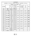
關於本實施例之TTL/ImgH、(ALT+EFL)/AAG、ALT/(G56+G78)、TL/(T6+G67)、(T1+T6+G78)/(BFL+T7)、(T1+G12+T2)/BFL、AAG/(G34+T4+G45)、AAG/T6、(T4+T8)/(G12+T2)、V1+V2+V4+V6+V7、(T2+T4+T6)/(G23+T3)、EFL/(T5+T8)、(TL+BFL)/(T4+T7)、ALT/(T6+G78)、AAG/(T1+T7+T8)、(T3+T4+T5)/(T2+BFL)、(G67+G78)/(G12+G23)、(G23+G34+G45+G56)/G78、(T1+T3+T5)/(G67+G78)請參考圖46A。TTL/ImgH, (ALT+EFL)/AAG, ALT/(G56+G78), TL/(T6+G67), (T1+T6+G78)/(BFL+T7), (T1+ G12+T2)/BFL, AAG/(G34+T4+G45), AAG/T6, (T4+T8)/(G12+T2), V1+V2+V4+V6+V7, (T2+T4+T6) /(G23+T3), EFL/(T5+T8), (TL+BFL)/(T4+T7), ALT/(T6+G78), AAG/(T1+T7+T8), (T3+T4+ T5)/(T2+BFL), (G67+G78)/(G12+G23), (G23+G34+G45+G56)/G78, (T1+T3+T5)/(G67+G78) Please refer to Figure 46A .
另請一併參考圖10至圖13,其中圖10繪示依據本發明之第二實施例之光學成像鏡頭2之透鏡剖面結構示意圖,圖11繪示依據本發明之第二實施例之光學成像鏡頭2之縱向球差與各項像差圖示意圖,圖12繪示依據本發明之第二實施例之光學成像鏡頭2之詳細光學數據,圖13繪示依據本發明之第二實施例之光學成像鏡頭2之各透鏡之非球面數據。Please also refer to FIG. 10 to FIG. 13, wherein FIG. 10 shows a schematic diagram of the lens cross-sectional structure of the
如圖10所示,本實施例之光學成像鏡頭2從物側A1至像側A2沿一光軸依序包括一光圈STO、一第一透鏡L1、一第二透鏡L2、一第三透鏡L3、一第四透鏡L4、一第五透鏡L5、一第六透鏡L6、一第七透鏡L7以及一第八透鏡L8。As shown in FIG. 10 , the
第二實施例之物側面L1A1、L2A1、L3A1、L4A1、L5A1、L6A1、L7A1、L8A1及像側面L1A2、L2A2、L3A2、L5A2、L6A2、L7A2、L8A2之表面的凹凸配置及各透鏡的屈光率配置大致上與第一實施例類似,然而第四透鏡L4之屈光率、第四透鏡L4之像側面L4A2之表面凹凸配置與第一實施例不同。此外,第二實施例的各透鏡表面的曲率半徑、透鏡厚度、透鏡非球面係數及系統焦距的光學參數也與第一實施例不同。具體來說,第四透鏡L4具有負屈光率,第四透鏡L4之像側面L4A2之光軸區域L4A2C為凹面。Concave-convex arrangement of the surface of the object side L1A1, L2A1, L3A1, L4A1, L5A1, L6A1, L7A1, L8A1 and image side L1A2, L2A2, L3A2, L5A2, L6A2, L7A2, L8A2 and the refractive index of each lens in the second embodiment The configuration is generally similar to that of the first embodiment, but the refractive power of the fourth lens L4 and the configuration of the surface bumps on the image side L4A2 of the fourth lens L4 are different from those of the first embodiment. In addition, the radius of curvature of each lens surface, lens thickness, lens aspheric coefficient, and optical parameters of the system focal length in the second embodiment are also different from those in the first embodiment. Specifically, the fourth lens L4 has a negative refractive power, and the optical axis area L4A2C of the image side L4A2 of the fourth lens L4 is a concave surface.
在此為了更清楚繪示本實施例之圖面,透鏡表面凹凸配置的特徵僅標示與第一實施例不同之處,而省略相同之處的標號。關於本實施例之光學成像鏡頭2的各透鏡之光學特性,請參考圖12。Here, in order to illustrate the drawing of this embodiment more clearly, the features of the concave-convex configuration on the lens surface are only marked with the difference from the first embodiment, and the reference numerals of the same parts are omitted. For the optical characteristics of each lens of the
從圖11(a)中每一曲線的縱向球差,可看出不同高度的離軸光線的成像點之偏差控制在±0.03 mm的範圍內。參閱圖11(b),三種代表波長在整個視場範圍內的場曲像差落在±0.03 mm的範圍內。參閱圖11(c),三種代表波長在整個視場範圍內的場曲像差落在±0.06 mm的範圍內。參閱圖11(d)的橫軸,光學成像鏡頭2的畸變像差維持在±4.5 %的範圍內。From the longitudinal spherical aberration of each curve in Figure 11(a), it can be seen that the deviation of the imaging points of off-axis rays at different heights is controlled within the range of ±0.03 mm. Referring to Figure 11(b), the field curvature aberrations of the three representative wavelengths in the entire field of view fall within the range of ±0.03 mm. Referring to Figure 11(c), the field curvature aberrations of the three representative wavelengths in the entire field of view fall within the range of ±0.06 mm. Referring to the horizontal axis of FIG. 11( d ), the distortion aberration of the
如圖11、12所示,相較於第一實施例,本實施例之光學成像鏡頭2之系統長度較短,半視角、像高較大,畸變像差較小。As shown in FIGS. 11 and 12 , compared with the first embodiment, the
關於本實施例之TTL/ImgH、(ALT+EFL)/AAG、ALT/(G56+G78)、TL/(T6+G67)、(T1+T6+G78)/(BFL+T7)、(T1+G12+T2)/BFL、AAG/(G34+T4+G45)、AAG/T6、(T4+T8)/(G12+T2)、V1+V2+V4+V6+V7、(T2+T4+T6)/(G23+T3)、EFL/(T5+T8)、(TL+BFL)/(T4+T7)、ALT/(T6+G78)、AAG/(T1+T7+T8)、(T3+T4+T5)/(T2+BFL)、(G67+G78)/(G12+G23)、(G23+G34+G45+G56)/G78、(T1+T3+T5)/(G67+G78)之數值,請參考圖46A。TTL/ImgH, (ALT+EFL)/AAG, ALT/(G56+G78), TL/(T6+G67), (T1+T6+G78)/(BFL+T7), (T1+ G12+T2)/BFL, AAG/(G34+T4+G45), AAG/T6, (T4+T8)/(G12+T2), V1+V2+V4+V6+V7, (T2+T4+T6) /(G23+T3), EFL/(T5+T8), (TL+BFL)/(T4+T7), ALT/(T6+G78), AAG/(T1+T7+T8), (T3+T4+ T5)/(T2+BFL), (G67+G78)/(G12+G23), (G23+G34+G45+G56)/G78, (T1+T3+T5)/(G67+G78), please Refer to Figure 46A.
另請一併參考圖14至圖17,其中圖14繪示依據本發明之第三實施例之光學成像鏡頭3之透鏡剖面結構示意圖,圖15繪示依據本發明之第三實施例之光學成像鏡頭3之縱向球差與各項像差圖示意圖,圖16繪示依據本發明之第三實施例之光學成像鏡頭3之詳細光學數據,圖17繪示依據本發明之第三實施例之光學成像鏡頭3之各透鏡之非球面數據。Please also refer to FIG. 14 to FIG. 17, wherein FIG. 14 shows a schematic diagram of the lens cross-sectional structure of the
如圖14所示,本實施例之光學成像鏡頭3從物側A1至像側A2沿一光軸依序包括一光圈STO、一第一透鏡L1、一第二透鏡L2、一第三透鏡L3、一第四透鏡L4、一第五透鏡L5、一第六透鏡L6、一第七透鏡L7以及一第八透鏡L8。As shown in Figure 14, the
第三實施例之物側面L1A1、L2A1、L3A1、L4A1、L5A1、L6A1、L7A1、L8A1及像側面L1A2、L2A2、L3A2、L5A2、L6A2、L7A2、L8A2之表面的凹凸配置及各透鏡的屈光率配置大致上與第一實施例類似,然而第四透鏡L4之屈光率、第四透鏡L4之像側面L4A2之表面凹凸配置與第一實施例不同。此外,第三實施例的各透鏡表面的曲率半徑、透鏡厚度、透鏡非球面係數及系統焦距的光學參數也與第一實施例不同。具體來說,第四透鏡L4具有負屈光率,第四透鏡L4之像側面L4A2之光軸區域L4A2C為凹面。Concave-convex arrangement and refractive index of each lens on the object side L1A1, L2A1, L3A1, L4A1, L5A1, L6A1, L7A1, L8A1 and image side L1A2, L2A2, L3A2, L5A2, L6A2, L7A2, L8A2 of the third embodiment The configuration is generally similar to that of the first embodiment, but the refractive power of the fourth lens L4 and the configuration of the surface bumps on the image side L4A2 of the fourth lens L4 are different from those of the first embodiment. In addition, the radius of curvature of each lens surface, lens thickness, lens aspheric coefficient, and optical parameters of the system focal length in the third embodiment are also different from those in the first embodiment. Specifically, the fourth lens L4 has a negative refractive power, and the optical axis area L4A2C of the image side L4A2 of the fourth lens L4 is a concave surface.
在此為了更清楚繪示本實施例之圖面,透鏡表面凹凸配置的特徵僅標示與第一實施例不同之處,而省略相同之處的標號。關於本實施例之光學成像鏡頭3的各透鏡之光學特性,請參考圖16。Here, in order to illustrate the drawing of this embodiment more clearly, the features of the concave-convex configuration on the lens surface are only marked with the difference from the first embodiment, and the reference numerals of the same parts are omitted. For the optical characteristics of each lens of the
從圖15(a)中每一曲線的縱向球差,可看出不同高度的離軸光線的成像點之偏差控制在±0.08 mm的範圍內。參閱圖15(b),三種代表波長在整個視場範圍內的場曲像差落在±0.08 mm的範圍內。參閱圖15(c),三種代表波長在整個視場範圍內的場曲像差落在±0.18 mm的範圍內。參閱圖15(d)的橫軸,光學成像鏡頭3的畸變像差維持在±10 %的範圍內。From the longitudinal spherical aberration of each curve in Fig. 15(a), it can be seen that the deviation of the imaging points of off-axis rays at different heights is controlled within the range of ±0.08 mm. Referring to Figure 15(b), the field curvature aberrations of the three representative wavelengths in the entire field of view fall within the range of ±0.08 mm. Referring to Figure 15(c), the field curvature aberrations of the three representative wavelengths in the entire field of view fall within the range of ±0.18 mm. Referring to the horizontal axis of FIG. 15( d ), the distortion aberration of the
如圖15、16所示,相較於第一實施例,本實施例之半視角、像高較大。As shown in Figures 15 and 16, compared with the first embodiment, the half angle of view and image height of this embodiment are larger.
關於本實施例之TTL/ImgH、(ALT+EFL)/AAG、ALT/(G56+G78)、TL/(T6+G67)、(T1+T6+G78)/(BFL+T7)、(T1+G12+T2)/BFL、AAG/(G34+T4+G45)、AAG/T6、(T4+T8)/(G12+T2)、V1+V2+V4+V6+V7、(T2+T4+T6)/(G23+T3)、EFL/(T5+T8)、(TL+BFL)/(T4+T7)、ALT/(T6+G78)、AAG/(T1+T7+T8)、(T3+T4+T5)/(T2+BFL)、(G67+G78)/(G12+G23)、(G23+G34+G45+G56)/G78、(T1+T3+T5)/(G67+G78)之數值,請參考圖46A。TTL/ImgH, (ALT+EFL)/AAG, ALT/(G56+G78), TL/(T6+G67), (T1+T6+G78)/(BFL+T7), (T1+ G12+T2)/BFL, AAG/(G34+T4+G45), AAG/T6, (T4+T8)/(G12+T2), V1+V2+V4+V6+V7, (T2+T4+T6) /(G23+T3), EFL/(T5+T8), (TL+BFL)/(T4+T7), ALT/(T6+G78), AAG/(T1+T7+T8), (T3+T4+ T5)/(T2+BFL), (G67+G78)/(G12+G23), (G23+G34+G45+G56)/G78, (T1+T3+T5)/(G67+G78), please Refer to Figure 46A.
另請一併參考圖18至圖21,其中圖18繪示依據本發明之第四實施例之光學成像鏡頭4之透鏡剖面結構示意圖,圖19繪示依據本發明之第四實施例之光學成像鏡頭4之縱向球差與各項像差圖示意圖,圖20繪示依據本發明之第四實施例之光學成像鏡頭4之詳細光學數據,圖21繪示依據本發明之第四實施例之光學成像鏡頭4之各透鏡之非球面數據。Please also refer to FIG. 18 to FIG. 21, wherein FIG. 18 shows a schematic diagram of the lens cross-sectional structure of the
如圖18所示,本實施例之光學成像鏡頭4從物側A1至像側A2沿一光軸依序包括一光圈STO、一第一透鏡L1、一第二透鏡L2、一第三透鏡L3、一第四透鏡L4、一第五透鏡L5、一第六透鏡L6、一第七透鏡L7以及一第八透鏡L8。As shown in Figure 18, the
第四實施例之物側面L1A1、L2A1、L4A1、L5A1、L6A1、L7A1及像側面L1A2、L2A2、L3A2、L5A2、L6A2、L7A2、L8A2之表面的凹凸配置及各透鏡的屈光率配置大致上與第一實施例類似,然而第四透鏡L4之屈光率、第三透鏡L3之物側面L3A1、第四透鏡L4之像側面L4A2、第八透鏡L8之物側面L8A1之表面凹凸配置與第一實施例不同。此外,第四實施例的各透鏡表面的曲率半徑、透鏡厚度、透鏡非球面係數及系統焦距的光學參數也與第一實施例不同。具體來說,第四透鏡L4具有負屈光率,第三透鏡L3之物側面L3A1之光軸區域L3A1C為凹面,第四透鏡L4之像側面L4A2之光軸區域L4A2C為凹面,第八透鏡L8之物側面L8A1之圓周區域L8A1P為凸面。The concavo-convex arrangement of the surface of the object side L1A1, L2A1, L4A1, L5A1, L6A1, L7A1 and the image side L1A2, L2A2, L3A2, L5A2, L6A2, L7A2, L8A2 of the fourth embodiment and the refractive index arrangement of each lens are roughly the same as The first embodiment is similar, but the refractive power of the fourth lens L4, the object side L3A1 of the third lens L3, the image side L4A2 of the fourth lens L4, and the surface concave-convex configuration of the object side L8A1 of the eighth lens L8 are the same as those of the first embodiment. Examples are different. In addition, the optical parameters of the radius of curvature of each lens surface, lens thickness, lens aspheric coefficient, and system focal length in the fourth embodiment are also different from those in the first embodiment. Specifically, the fourth lens L4 has a negative refractive power, the optical axis area L3A1C of the object side L3A1 of the third lens L3 is concave, the optical axis area L4A2C of the image side L4A2 of the fourth lens L4 is concave, and the eighth lens L8 The peripheral region L8A1P of the side surface L8A1 of the object is a convex surface.
在此為了更清楚繪示本實施例之圖面,透鏡表面凹凸配置的特徵僅標示與第一實施例不同之處,而省略相同之處的標號。關於本實施例之光學成像鏡頭4的各透鏡之光學特性,請參考圖20。Here, in order to illustrate the drawing of this embodiment more clearly, the features of the concave-convex configuration on the lens surface are only marked with the difference from the first embodiment, and the reference numerals of the same parts are omitted. For the optical characteristics of each lens of the
從圖19(a)中每一曲線的縱向球差,可看出不同高度的離軸光線的成像點之偏差控制在±0.025 mm的範圍內。參閱圖19(b),三種代表波長在整個視場範圍內的場曲像差落在±0.03 mm的範圍內。參閱圖19(c),三種代表波長在整個視場範圍內的場曲像差落在±0.04 mm的範圍內。參閱圖19(d)的橫軸,光學成像鏡頭4的畸變像差維持在±8 %的範圍內。From the longitudinal spherical aberration of each curve in Figure 19(a), it can be seen that the deviation of the imaging points of off-axis rays at different heights is controlled within the range of ±0.025 mm. Referring to Figure 19(b), the field curvature aberrations of the three representative wavelengths in the entire field of view fall within the range of ±0.03 mm. Referring to Figure 19(c), the field curvature aberrations of the three representative wavelengths in the entire field of view fall within the range of ±0.04 mm. Referring to the horizontal axis of FIG. 19( d ), the distortion aberration of the
如圖19、20所示,相較於第一實施例,本實施例之像高較大,系統長度較短。As shown in Figures 19 and 20, compared with the first embodiment, the image height of this embodiment is larger and the system length is shorter.
關於本實施例之TTL/ImgH、(ALT+EFL)/AAG、ALT/(G56+G78)、TL/(T6+G67)、(T1+T6+G78)/(BFL+T7)、(T1+G12+T2)/BFL、AAG/(G34+T4+G45)、AAG/T6、(T4+T8)/(G12+T2)、V1+V2+V4+V6+V7、(T2+T4+T6)/(G23+T3)、EFL/(T5+T8)、(TL+BFL)/(T4+T7)、ALT/(T6+G78)、AAG/(T1+T7+T8)、(T3+T4+T5)/(T2+BFL)、(G67+G78)/(G12+G23)、(G23+G34+G45+G56)/G78、(T1+T3+T5)/(G67+G78)之數值,請參考圖46A。TTL/ImgH, (ALT+EFL)/AAG, ALT/(G56+G78), TL/(T6+G67), (T1+T6+G78)/(BFL+T7), (T1+ G12+T2)/BFL, AAG/(G34+T4+G45), AAG/T6, (T4+T8)/(G12+T2), V1+V2+V4+V6+V7, (T2+T4+T6) /(G23+T3), EFL/(T5+T8), (TL+BFL)/(T4+T7), ALT/(T6+G78), AAG/(T1+T7+T8), (T3+T4+ T5)/(T2+BFL), (G67+G78)/(G12+G23), (G23+G34+G45+G56)/G78, (T1+T3+T5)/(G67+G78), please Refer to Figure 46A.
另請一併參考圖22至圖25,其中圖22繪示依據本發明之第五實施例之光學成像鏡頭5之透鏡剖面結構示意圖,圖23繪示依據本發明之第五實施例之光學成像鏡頭5之縱向球差與各項像差圖示意圖,圖24繪示依據本發明之第五實施例之光學成像鏡頭5之詳細光學數據,圖25繪示依據本發明之第五實施例之光學成像鏡頭5之各透鏡之非球面數據。Please also refer to FIG. 22 to FIG. 25, wherein FIG. 22 shows a schematic diagram of the lens cross-sectional structure of the
如圖22所示,本實施例之光學成像鏡頭5從物側A1至像側A2沿一光軸依序包括一光圈STO、一第一透鏡L1、一第二透鏡L2、一第三透鏡L3、一第四透鏡L4、一第五透鏡L5、一第六透鏡L6、一第七透鏡L7以及一第八透鏡L8。As shown in Figure 22, the
第五實施例之物側面L1A1、L2A1、L3A1、L5A1、L6A1、L7A1、L8A1及像側面L1A2、L2A2、L3A2、L4A2、L5A2、L6A2、L7A2、L8A2之表面的凹凸配置及各透鏡的屈光率配置大致上與第一實施例類似,然而第六透鏡L6的屈光率、第四透鏡L4之物側面L4A1之表面凹凸配置與第一實施例不同。此外,第五實施例的各透鏡表面的曲率半徑、透鏡厚度、透鏡非球面係數及系統焦距的光學參數也與第一實施例不同。具體來說,第四透鏡L4之物側面L4A1之光軸區域L4A1C為凹面,第六透鏡L6具有負屈光率。Concave-convex arrangement of the surface of object side L1A1, L2A1, L3A1, L5A1, L6A1, L7A1, L8A1 and image side L1A2, L2A2, L3A2, L4A2, L5A2, L6A2, L7A2, L8A2 and the refractive power of each lens The configuration is generally similar to that of the first embodiment, but the refractive power of the sixth lens L6 and the surface concavo-convex configuration of the object side surface L4A1 of the fourth lens L4 are different from those of the first embodiment. In addition, the radius of curvature of each lens surface, lens thickness, lens aspheric coefficient, and optical parameters of the system focal length in the fifth embodiment are also different from those in the first embodiment. Specifically, the optical axis area L4A1C of the object side surface L4A1 of the fourth lens L4 is concave, and the sixth lens L6 has a negative refractive power.
在此為了更清楚繪示本實施例之圖面,透鏡表面凹凸配置的特徵僅標示與第一實施例不同之處,而省略相同之處的標號。關於本實施例之光學成像鏡頭5的各透鏡之光學特性,請參考圖24。Here, in order to illustrate the drawing of this embodiment more clearly, the features of the concave-convex configuration on the lens surface are only marked with the difference from the first embodiment, and the reference numerals of the same parts are omitted. For the optical characteristics of each lens of the
從圖23(a)中每一曲線的縱向球差,可看出不同高度的離軸光線的成像點之偏差控制在±0.05 mm的範圍內。參閱圖23(b),三種代表波長在整個視場範圍內的場曲像差落在±0.05 mm的範圍內。參閱圖23(c),三種代表波長在整個視場範圍內的場曲像差落在±0.05 mm的範圍內。參閱圖23(d)的橫軸,光學成像鏡頭5的畸變像差維持在±8 %的範圍內。From the longitudinal spherical aberration of each curve in Figure 23(a), it can be seen that the deviation of the imaging points of off-axis rays at different heights is controlled within the range of ±0.05 mm. Referring to Figure 23(b), the field curvature aberrations of the three representative wavelengths in the entire field of view fall within the range of ±0.05 mm. Referring to Figure 23(c), the field curvature aberrations of the three representative wavelengths in the entire field of view fall within the range of ±0.05 mm. Referring to the horizontal axis of FIG. 23( d ), the distortion aberration of the
如圖23、24所示,相較於第一實施例,本實施例易於製造,因此良率較高。As shown in FIGS. 23 and 24 , compared with the first embodiment, this embodiment is easier to manufacture, so the yield rate is higher.
關於本實施例之TTL/ImgH、(ALT+EFL)/AAG、ALT/(G56+G78)、TL/(T6+G67)、(T1+T6+G78)/(BFL+T7)、(T1+G12+T2)/BFL、AAG/(G34+T4+G45)、AAG/T6、(T4+T8)/(G12+T2)、V1+V2+V4+V6+V7、(T2+T4+T6)/(G23+T3)、EFL/(T5+T8)、(TL+BFL)/(T4+T7)、ALT/(T6+G78)、AAG/(T1+T7+T8)、(T3+T4+T5)/(T2+BFL)、(G67+G78)/(G12+G23)、(G23+G34+G45+G56)/G78、(T1+T3+T5)/(G67+G78)之數值,請參考圖46A。TTL/ImgH, (ALT+EFL)/AAG, ALT/(G56+G78), TL/(T6+G67), (T1+T6+G78)/(BFL+T7), (T1+ G12+T2)/BFL, AAG/(G34+T4+G45), AAG/T6, (T4+T8)/(G12+T2), V1+V2+V4+V6+V7, (T2+T4+T6) /(G23+T3), EFL/(T5+T8), (TL+BFL)/(T4+T7), ALT/(T6+G78), AAG/(T1+T7+T8), (T3+T4+ T5)/(T2+BFL), (G67+G78)/(G12+G23), (G23+G34+G45+G56)/G78, (T1+T3+T5)/(G67+G78), please Refer to Figure 46A.
另請一併參考圖26至圖29,其中圖26繪示依據本發明之第六實施例之光學成像鏡頭6之透鏡剖面結構示意圖,圖27繪示依據本發明之第六實施例之光學成像鏡頭6之縱向球差與各項像差圖示意圖,圖28繪示依據本發明之第六實施例之光學成像鏡頭6之詳細光學數據,圖29繪示依據本發明之第六實施例之光學成像鏡頭6之各透鏡之非球面數據。Please also refer to FIG. 26 to FIG. 29, wherein FIG. 26 shows a schematic diagram of the lens cross-sectional structure of the
如圖26所示,本實施例之光學成像鏡頭6從物側A1至像側A2沿一光軸依序包括一光圈STO、一第一透鏡L1、一第二透鏡L2、一第三透鏡L3、一第四透鏡L4、一第五透鏡L5、一第六透鏡L6、一第七透鏡L7以及一第八透鏡L8。As shown in Figure 26, the
第六實施例之物側面L1A1、L2A1、L4A1、L5A1、L6A1、L7A1、L8A1及像側面L1A2、L2A2、L3A2、L5A2、L6A2、L7A2之表面的凹凸配置及各透鏡的屈光率配置大致上與第一實施例類似,然而第三透鏡L3之物側面L3A1、第四透鏡L4之像側面L4A2、第八透鏡L8之像側面L8A2之表面凹凸配置、第四透鏡L4之屈光率、第八透鏡L8之屈光率與第一實施例不同。此外,第六實施例的各透鏡表面的曲率半徑、透鏡厚度、透鏡非球面係數及系統焦距的光學參數也與第一實施例不同。具體來說,第三透鏡L3之物側面L3A1之光軸區域L3A1C為凹面,第四透鏡L4之像側面L4A2之光軸區域L4A2C為凹面,第八透鏡L8之像側面L8A2之光軸區域L8A2C為凸面,第四透鏡L4具有負屈光率,第八透鏡L8具有正屈光率。The arrangement of concavities and convexities on the surface of the object side L1A1, L2A1, L4A1, L5A1, L6A1, L7A1, L8A1 and the image side L1A2, L2A2, L3A2, L5A2, L6A2, L7A2 of the sixth embodiment and the refractive index arrangement of each lens are roughly the same as The first embodiment is similar, but the surface concave-convex configuration of the object side L3A1 of the third lens L3, the image side L4A2 of the fourth lens L4, the image side L8A2 of the eighth lens L8, the refractive power of the fourth lens L4, the eighth lens The refractive index of L8 is different from that of the first embodiment. In addition, the radius of curvature of each lens surface, lens thickness, lens aspheric coefficient, and optical parameters of the system focal length in the sixth embodiment are also different from those in the first embodiment. Specifically, the optical axis area L3A1C of the object side L3A1 of the third lens L3 is concave, the optical axis area L4A2C of the image side L4A2 of the fourth lens L4 is concave, and the optical axis area L8A2C of the image side L8A2 of the eighth lens L8 is Convex, the fourth lens L4 has a negative refractive power, and the eighth lens L8 has a positive refractive power.
在此為了更清楚繪示本實施例之圖面,透鏡表面凹凸配置的特徵僅標示與第一實施例不同之處,而省略相同之處的標號。關於本實施例之光學成像鏡頭6的各透鏡之光學特性,請參考圖28。Here, in order to illustrate the drawing of this embodiment more clearly, the features of the concave-convex configuration on the lens surface are only marked with the difference from the first embodiment, and the reference numerals of the same parts are omitted. For the optical characteristics of each lens of the
從圖27(a)中每一曲線的縱向球差,可看出不同高度的離軸光線的成像點之偏差控制在±0.06 mm的範圍內。參閱圖27(b),三種代表波長在整個視場範圍內的場曲像差落在±0.06 mm的範圍內。參閱圖27(c),三種代表波長在整個視場範圍內的場曲像差落在±0.20 mm的範圍內。參閱圖27(d)的橫軸,光學成像鏡頭6的畸變像差維持在±12 %的範圍內。From the longitudinal spherical aberration of each curve in Figure 27(a), it can be seen that the deviation of the imaging points of off-axis rays at different heights is controlled within the range of ±0.06 mm. Referring to Figure 27(b), the field curvature aberrations of the three representative wavelengths in the entire field of view fall within the range of ±0.06 mm. Referring to Figure 27(c), the field curvature aberrations of the three representative wavelengths in the entire field of view fall within the range of ±0.20 mm. Referring to the horizontal axis of FIG. 27( d ), the distortion aberration of the
如圖27、28所示,相較於第一實施例,本實施例易於製造,因此良率較高。As shown in FIGS. 27 and 28 , compared with the first embodiment, this embodiment is easier to manufacture, so the yield rate is higher.
關於本實施例之TTL/ImgH、(ALT+EFL)/AAG、ALT/(G56+G78)、TL/(T6+G67)、(T1+T6+G78)/(BFL+T7)、(T1+G12+T2)/BFL、AAG/(G34+T4+G45)、AAG/T6、(T4+T8)/(G12+T2)、V1+V2+V4+V6+V7、(T2+T4+T6)/(G23+T3)、EFL/(T5+T8)、(TL+BFL)/(T4+T7)、ALT/(T6+G78)、AAG/(T1+T7+T8)、(T3+T4+T5)/(T2+BFL)、(G67+G78)/(G12+G23)、(G23+G34+G45+G56)/G78、(T1+T3+T5)/(G67+G78)數值,請參考圖46B。TTL/ImgH, (ALT+EFL)/AAG, ALT/(G56+G78), TL/(T6+G67), (T1+T6+G78)/(BFL+T7), (T1+ G12+T2)/BFL, AAG/(G34+T4+G45), AAG/T6, (T4+T8)/(G12+T2), V1+V2+V4+V6+V7, (T2+T4+T6) /(G23+T3), EFL/(T5+T8), (TL+BFL)/(T4+T7), ALT/(T6+G78), AAG/(T1+T7+T8), (T3+T4+ T5)/(T2+BFL), (G67+G78)/(G12+G23), (G23+G34+G45+G56)/G78, (T1+T3+T5)/(G67+G78) values, please refer to Figure 46B.
另請一併參考圖30至圖33,其中圖30繪示依據本發明之第七實施例之光學成像鏡頭7之透鏡剖面結構示意圖,圖31繪示依據本發明之第七實施例之光學成像鏡頭7之縱向球差與各項像差圖示意圖,圖32繪示依據本發明之第七實施例之光學成像鏡頭7之詳細光學數據,圖33繪示依據本發明之第七實施例之光學成像鏡頭7之各透鏡之非球面數據。Please also refer to FIG. 30 to FIG. 33 , wherein FIG. 30 shows a schematic diagram of the lens cross-sectional structure of the
如圖30所示,本實施例之光學成像鏡頭7從物側A1至像側A2沿一光軸依序包括一光圈STO、一第一透鏡L1、一第二透鏡L2、一第三透鏡L3、一第四透鏡L4、一第五透鏡L5、一第六透鏡L6、一第七透鏡L7以及一第八透鏡L8。As shown in Figure 30, the
第七實施例之物側面L1A1、L2A1、L3A1、L5A1、L6A1、L7A1、L8A1及像側面L1A2、L2A2、L3A2、L4A2、L5A2、L6A2、L7A2、L8A2之表面的凹凸配置及各透鏡的屈光率配置大致上與第一實施例類似,然而第四透鏡L4之物側面L4A1之表面凹凸配置與第一實施例不同。此外,第七實施例的各透鏡表面的曲率半徑、透鏡厚度、透鏡非球面係數及系統焦距的光學參數也與第一實施例不同。具體來說,第四透鏡L4之物側面L4A1之光軸區域L4A1C為凹面。Concave-convex arrangement and refractive index of each lens on object side L1A1, L2A1, L3A1, L5A1, L6A1, L7A1, L8A1 and image side L1A2, L2A2, L3A2, L4A2, L5A2, L6A2, L7A2, L8A2 The configuration is substantially similar to that of the first embodiment, but the surface concavo-convex configuration of the object side surface L4A1 of the fourth lens L4 is different from that of the first embodiment. In addition, the radius of curvature of each lens surface, lens thickness, lens aspheric coefficient, and optical parameters of the system focal length in the seventh embodiment are also different from those in the first embodiment. Specifically, the optical axis area L4A1C of the object side surface L4A1 of the fourth lens L4 is a concave surface.
在此為了更清楚繪示本實施例之圖面,透鏡表面凹凸配置的特徵僅標示與第一實施例不同之處,而省略相同之處的標號。關於本實施例之光學成像鏡頭7的各透鏡之光學特性,請參考圖32。Here, in order to illustrate the drawing of this embodiment more clearly, the features of the concave-convex configuration on the lens surface are only marked with the difference from the first embodiment, and the reference numerals of the same parts are omitted. For the optical characteristics of each lens of the
從圖31(a)中每一曲線的縱向球差,可看出不同高度的離軸光線的成像點之偏差控制在±0.09 mm的範圍內。參閱圖31(b),三種代表波長在整個視場範圍內的場曲像差落在±0.09 mm的範圍內。參閱圖31(c),三種代表波長在整個視場範圍內的場曲像差落在±0.09 mm的範圍內。參閱圖31(d)的橫軸,光學成像鏡頭7的畸變像差維持在±35 %的範圍內。From the longitudinal spherical aberration of each curve in Figure 31(a), it can be seen that the deviation of the imaging points of off-axis rays at different heights is controlled within the range of ±0.09 mm. Referring to Figure 31(b), the field curvature aberrations of the three representative wavelengths in the entire field of view fall within the range of ±0.09 mm. Referring to Figure 31(c), the field curvature aberrations of the three representative wavelengths in the entire field of view fall within the range of ±0.09 mm. Referring to the horizontal axis of FIG. 31( d ), the distortion aberration of the
如圖31、32所示,相較於第一實施例,本實施例之像高較大。As shown in Figures 31 and 32, compared with the first embodiment, the image height of this embodiment is larger.
關於本實施例之TTL/ImgH、(ALT+EFL)/AAG、ALT/(G56+G78)、TL/(T6+G67)、(T1+T6+G78)/(BFL+T7)、(T1+G12+T2)/BFL、AAG/(G34+T4+G45)、AAG/T6、(T4+T8)/(G12+T2)、V1+V2+V4+V6+V7、(T2+T4+T6)/(G23+T3)、EFL/(T5+T8)、(TL+BFL)/(T4+T7)、ALT/(T6+G78)、AAG/(T1+T7+T8)、(T3+T4+T5)/(T2+BFL)、(G67+G78)/(G12+G23)、(G23+G34+G45+G56)/G78、(T1+T3+T5)/(G67+G78)之數值,請參考圖46B。TTL/ImgH, (ALT+EFL)/AAG, ALT/(G56+G78), TL/(T6+G67), (T1+T6+G78)/(BFL+T7), (T1+ G12+T2)/BFL, AAG/(G34+T4+G45), AAG/T6, (T4+T8)/(G12+T2), V1+V2+V4+V6+V7, (T2+T4+T6) /(G23+T3), EFL/(T5+T8), (TL+BFL)/(T4+T7), ALT/(T6+G78), AAG/(T1+T7+T8), (T3+T4+ T5)/(T2+BFL), (G67+G78)/(G12+G23), (G23+G34+G45+G56)/G78, (T1+T3+T5)/(G67+G78), please Refer to Figure 46B.
另請一併參考圖34至圖37,其中圖34繪示依據本發明之第八實施例之光學成像鏡頭8之透鏡剖面結構示意圖,圖35繪示依據本發明之第八實施例之光學成像鏡頭8之縱向球差與各項像差圖示意圖,圖36繪示依據本發明之第八實施例之光學成像鏡頭8之詳細光學數據,圖37繪示依據本發明之第八實施例之光學成像鏡頭8之各透鏡之非球面數據。Please also refer to FIG. 34 to FIG. 37 , wherein FIG. 34 shows a schematic diagram of the lens sectional structure of the
如圖34所示,本實施例之光學成像鏡頭8從物側A1至像側A2沿一光軸依序包括一光圈STO、一第一透鏡L1、一第二透鏡L2、一第三透鏡L3、一第四透鏡L4、一第五透鏡L5、一第六透鏡L6、一第七透鏡L7以及一第八透鏡L8。As shown in Figure 34, the
第八實施例之物側面L1A1、L2A1、L4A1、L5A1、L6A1、L7A1、L8A1及像側面L1A2、L2A2、L3A2、L5A2、L6A2、L7A2、L8A2之表面的凹凸配置及各透鏡的屈光率配置大致上與第一實施例類似,然而第三透鏡L3之物側面L3A1、第四透鏡L4之像側面L4A2之表面凹凸配置與第一實施例不同。此外,第八實施例的各透鏡表面的曲率半徑、透鏡厚度、透鏡非球面係數及系統焦距的光學參數也與第一實施例不同。具體來說,第三透鏡L3之物側面L3A1之圓周區域L3A1P為凸面,第四透鏡L4之像側面L4A2之光軸區域L4A2C為凹面。In the eighth embodiment, the concavo-convex arrangement of the surface of the object side L1A1, L2A1, L4A1, L5A1, L6A1, L7A1, L8A1 and the image side L1A2, L2A2, L3A2, L5A2, L6A2, L7A2, L8A2 and the refractive index arrangement of each lens are roughly The above is similar to the first embodiment, but the configuration of surface concavo-convex on the object side L3A1 of the third lens L3 and the image side L4A2 of the fourth lens L4 is different from the first embodiment. In addition, the radius of curvature of each lens surface, lens thickness, lens aspheric coefficient, and optical parameters of the system focal length in the eighth embodiment are also different from those in the first embodiment. Specifically, the circumferential area L3A1P of the object side L3A1 of the third lens L3 is convex, and the optical axis area L4A2C of the image side L4A2 of the fourth lens L4 is concave.
在此為了更清楚繪示本實施例之圖面,透鏡表面凹凸配置的特徵僅標示與第一實施例不同之處,而省略相同之處的標號。關於本實施例之光學成像鏡頭8的各透鏡之光學特性,請參考圖36。Here, in order to illustrate the drawing of this embodiment more clearly, the features of the concave-convex configuration on the lens surface are only marked with the difference from the first embodiment, and the reference numerals of the same parts are omitted. For the optical characteristics of each lens of the
從圖35(a)中每一曲線的縱向球差,可看出不同高度的離軸光線的成像點之偏差控制在±0.05 mm的範圍內。參閱圖35(b),三種代表波長在整個視場範圍內的場曲像差落在±0.06 mm的範圍內。參閱圖35(c),三種代表波長在整個視場範圍內的場曲像差落在±0.12 mm的範圍內。參閱圖35(d)的橫軸,光學成像鏡頭8的畸變像差維持在±25 %的範圍內。From the longitudinal spherical aberration of each curve in Figure 35(a), it can be seen that the deviation of the imaging points of off-axis rays at different heights is controlled within the range of ±0.05 mm. Referring to Figure 35(b), the field curvature aberrations of the three representative wavelengths in the entire field of view fall within the range of ±0.06 mm. Referring to Figure 35(c), the field curvature aberrations of the three representative wavelengths in the entire field of view fall within the range of ±0.12 mm. Referring to the horizontal axis of FIG. 35( d ), the distortion aberration of the
如圖35、36所示,相較於第一實施例,本實施例之半視角、像高較大,系統長度較短。As shown in Figures 35 and 36, compared with the first embodiment, the half viewing angle and image height of this embodiment are larger, and the system length is shorter.
關於本實施例之TTL/ImgH、(ALT+EFL)/AAG、ALT/(G56+G78)、TL/(T6+G67)、(T1+T6+G78)/(BFL+T7)、(T1+G12+T2)/BFL、AAG/(G34+T4+G45)、AAG/T6、(T4+T8)/(G12+T2)、V1+V2+V4+V6+V7、(T2+T4+T6)/(G23+T3)、EFL/(T5+T8)、(TL+BFL)/(T4+T7)、ALT/(T6+G78)、AAG/(T1+T7+T8)、(T3+T4+T5)/(T2+BFL)、(G67+G78)/(G12+G23)、(G23+G34+G45+G56)/G78、(T1+T3+T5)/(G67+G78)之數值,請參考圖46B。TTL/ImgH, (ALT+EFL)/AAG, ALT/(G56+G78), TL/(T6+G67), (T1+T6+G78)/(BFL+T7), (T1+ G12+T2)/BFL, AAG/(G34+T4+G45), AAG/T6, (T4+T8)/(G12+T2), V1+V2+V4+V6+V7, (T2+T4+T6) /(G23+T3), EFL/(T5+T8), (TL+BFL)/(T4+T7), ALT/(T6+G78), AAG/(T1+T7+T8), (T3+T4+ T5)/(T2+BFL), (G67+G78)/(G12+G23), (G23+G34+G45+G56)/G78, (T1+T3+T5)/(G67+G78), please Refer to Figure 46B.
另請一併參考圖38至圖41,其中圖38繪示依據本發明之第九實施例之光學成像鏡頭9之透鏡剖面結構示意圖,圖39繪示依據本發明之第九實施例之光學成像鏡頭9之縱向球差與各項像差圖示意圖,圖40繪示依據本發明之第九實施例之光學成像鏡頭9之詳細光學數據,圖41繪示依據本發明之第九實施例之光學成像鏡頭9之各透鏡之非球面數據。Please also refer to FIG. 38 to FIG. 41, wherein FIG. 38 shows a schematic diagram of the lens cross-sectional structure of the optical imaging lens 9 according to the ninth embodiment of the present invention, and FIG. 39 shows the optical imaging according to the ninth embodiment of the present invention Schematic diagram of the longitudinal spherical aberration and various aberration diagrams of the lens 9, FIG. 40 shows the detailed optical data of the optical imaging lens 9 according to the ninth embodiment of the present invention, and FIG. 41 shows the optical imaging lens 9 according to the ninth embodiment of the present invention The aspherical data of each lens of the imaging lens 9.
如圖38所示,本實施例之光學成像鏡頭9從物側A1至像側A2沿一光軸依序包括一光圈STO、一第一透鏡L1、一第二透鏡L2、一第三透鏡L3、一第四透鏡L4、一第五透鏡L5、一第六透鏡L6、一第七透鏡L7以及一第八透鏡L8。As shown in Figure 38, the optical imaging lens 9 of this embodiment includes an aperture STO, a first lens L1, a second lens L2, and a third lens L3 along an optical axis in sequence from the object side A1 to the image side A2 , a fourth lens L4, a fifth lens L5, a sixth lens L6, a seventh lens L7 and an eighth lens L8.
第九實施例之物側面L1A1、L2A1、L3A1、L4A1、L5A1、L6A1、L7A1、L8A1及像側面L1A2、L2A2、L5A2、L6A2、L7A2、L8A2之表面的凹凸配置及各透鏡的屈光率配置大致上與第一實施例類似,然而第三透鏡L3之像側面L3A2、第四透鏡L4之像側面L4A2之表面凹凸配置、第三透鏡L3之屈光率與第一實施例不同。此外,第九實施例的各透鏡表面的曲率半徑、透鏡厚度、透鏡非球面係數及系統焦距的光學參數也與第一實施例不同。具體來說,第三透鏡L3具有負屈光率,第三透鏡L3之像側面L3A2之光軸區域L3A2C為凹面,第四透鏡L4之像側面L4A2之光軸區域L4A2C為凹面。The concavo-convex arrangement of the surface of the object side L1A1, L2A1, L3A1, L4A1, L5A1, L6A1, L7A1, L8A1 and image side L1A2, L2A2, L5A2, L6A2, L7A2, L8A2 and the refractive index arrangement of each lens are roughly The above is similar to the first embodiment, but the surface concave-convex configuration of the image side L3A2 of the third lens L3, the image side L4A2 of the fourth lens L4, and the refractive power of the third lens L3 are different from the first embodiment. In addition, the radius of curvature of each lens surface, lens thickness, lens aspheric coefficient, and optical parameters of the system focal length in the ninth embodiment are also different from those in the first embodiment. Specifically, the third lens L3 has a negative refractive power, the optical axis area L3A2C of the image side L3A2 of the third lens L3 is concave, and the optical axis area L4A2C of the image side L4A2 of the fourth lens L4 is concave.
在此為了更清楚繪示本實施例之圖面,透鏡表面凹凸配置的特徵僅標示與第一實施例不同之處,而省略相同之處的標號。關於本實施例之光學成像鏡頭9的各透鏡之光學特性,請參考圖40。Here, in order to illustrate the drawing of this embodiment more clearly, the features of the concave-convex configuration on the lens surface are only marked with the difference from the first embodiment, and the reference numerals of the same parts are omitted. For the optical characteristics of each lens of the optical imaging lens 9 of this embodiment, please refer to FIG. 40 .
從圖39(a)中每一曲線的縱向球差,可看出不同高度的離軸光線的成像點之偏差控制在±0.05 mm的範圍內。參閱圖39(b),三種代表波長在整個視場範圍內的場曲像差落在±0.05 mm的範圍內。參閱圖39(c),三種代表波長在整個視場範圍內的場曲像差落在±0.05 mm的範圍內。參閱圖39(d)的橫軸,光學成像鏡頭9的畸變像差維持在±30 %的範圍內。From the longitudinal spherical aberration of each curve in Figure 39(a), it can be seen that the deviation of the imaging points of off-axis rays at different heights is controlled within the range of ±0.05 mm. Referring to Figure 39(b), the field curvature aberrations of the three representative wavelengths in the entire field of view fall within the range of ±0.05 mm. Referring to Fig. 39(c), the field curvature aberrations of the three representative wavelengths in the entire field of view fall within the range of ±0.05 mm. Referring to the horizontal axis of FIG. 39( d ), the distortion aberration of the optical imaging lens 9 is maintained within the range of ±30%.
如圖39、40所示,相較於第一實施例,本實施例之像高較大。As shown in Figures 39 and 40, compared with the first embodiment, the image height of this embodiment is larger.
關於本實施例之TTL/ImgH、(ALT+EFL)/AAG、ALT/(G56+G78)、TL/(T6+G67)、(T1+T6+G78)/(BFL+T7)、(T1+G12+T2)/BFL、AAG/(G34+T4+G45)、AAG/T6、(T4+T8)/(G12+T2)、V1+V2+V4+V6+V7、(T2+T4+T6)/(G23+T3)、EFL/(T5+T8)、(TL+BFL)/(T4+T7)、ALT/(T6+G78)、AAG/(T1+T7+T8)、(T3+T4+T5)/(T2+BFL)、(G67+G78)/(G12+G23)、(G23+G34+G45+G56)/G78、(T1+T3+T5)/(G67+G78)之數值,請參考圖46B。TTL/ImgH, (ALT+EFL)/AAG, ALT/(G56+G78), TL/(T6+G67), (T1+T6+G78)/(BFL+T7), (T1+ G12+T2)/BFL, AAG/(G34+T4+G45), AAG/T6, (T4+T8)/(G12+T2), V1+V2+V4+V6+V7, (T2+T4+T6) /(G23+T3), EFL/(T5+T8), (TL+BFL)/(T4+T7), ALT/(T6+G78), AAG/(T1+T7+T8), (T3+T4+ T5)/(T2+BFL), (G67+G78)/(G12+G23), (G23+G34+G45+G56)/G78, (T1+T3+T5)/(G67+G78), please Refer to Figure 46B.
另請一併參考圖42至圖45,其中圖42繪示依據本發明之第十實施例之光學成像鏡頭10之透鏡剖面結構示意圖,圖43繪示依據本發明之第十實施例之光學成像鏡頭10之縱向球差與各項像差圖示意圖,圖44繪示依據本發明之第十實施例之光學成像鏡頭10之詳細光學數據,圖45繪示依據本發明之第十實施例之光學成像鏡頭10之各透鏡之非球面數據。Please also refer to FIG. 42 to FIG. 45, wherein FIG. 42 shows a schematic diagram of the lens cross-sectional structure of the
如圖42所示,本實施例之光學成像鏡頭10從物側A1至像側A2沿一光軸依序包括一光圈STO、一第一透鏡L1、一第二透鏡L2、一第三透鏡L3、一第四透鏡L4、一第五透鏡L5、一第六透鏡L6、一第七透鏡L7以及一第八透鏡L8。As shown in FIG. 42, the
第十實施例之物側面L1A1、L2A1、L3A1、L4A1、L5A1、L6A1、L7A1、L8A1及像側面L1A2、L2A2、L3A2、L5A2、L6A2、L7A2、L8A2之表面的凹凸配置及各透鏡的屈光率配置大致上與第一實施例類似,然而第四透鏡L4之屈光率、第四透鏡L4之像側面L4A2之表面凹凸配置與第一實施例不同。此外,第十實施例的各透鏡表面的曲率半徑、透鏡厚度、透鏡非球面係數及系統焦距的光學參數也與第一實施例不同。具體來說,第四透鏡L4具有負屈光率,第四透鏡L4之像側面L4A2之光軸區域L4A2C為凹面。Concave-convex arrangement and refractive index of each lens on object side L1A1, L2A1, L3A1, L4A1, L5A1, L6A1, L7A1, L8A1 and image side L1A2, L2A2, L3A2, L5A2, L6A2, L7A2, L8A2 The configuration is generally similar to that of the first embodiment, but the refractive power of the fourth lens L4 and the configuration of the surface bumps on the image side L4A2 of the fourth lens L4 are different from those of the first embodiment. In addition, the radius of curvature of each lens surface, lens thickness, lens aspheric coefficient, and optical parameters of the system focal length in the tenth embodiment are also different from those in the first embodiment. Specifically, the fourth lens L4 has a negative refractive power, and the optical axis area L4A2C of the image side L4A2 of the fourth lens L4 is a concave surface.
在此為了更清楚繪示本實施例之圖面,透鏡表面凹凸配置的特徵僅標示與第一實施例不同之處,而省略相同之處的標號。關於本實施例之光學成像鏡頭10的各透鏡之光學特性,請參考圖44。Here, in order to illustrate the drawing of this embodiment more clearly, the features of the concave-convex configuration on the lens surface are only marked with the difference from the first embodiment, and the reference numerals of the same parts are omitted. For the optical characteristics of each lens of the
從圖43(a)中每一曲線的縱向球差,可看出不同高度的離軸光線的成像點之偏差控制在±0.08 mm的範圍內。參閱圖43(b),三種代表波長在整個視場範圍內的場曲像差落在±0.08 mm的範圍內。參閱圖43(c),三種代表波長在整個視場範圍內的場曲像差落在±0.16 mm的範圍內。參閱圖43(d)的橫軸,光學成像鏡頭10的畸變像差維持在±6 %的範圍內。From the longitudinal spherical aberration of each curve in Figure 43(a), it can be seen that the deviation of the imaging points of off-axis rays at different heights is controlled within the range of ±0.08 mm. Referring to Figure 43(b), the field curvature aberrations of the three representative wavelengths in the entire field of view fall within the range of ±0.08 mm. Referring to Fig. 43(c), the field curvature aberrations of the three representative wavelengths in the entire field of view fall within the range of ±0.16 mm. Referring to the horizontal axis of FIG. 43( d ), the distortion aberration of the
如圖43、44所示,相較於第一實施例,本實施例之像高較大。As shown in Figures 43 and 44, compared with the first embodiment, the image height of this embodiment is larger.
關於本實施例之TTL/ImgH、(ALT+EFL)/AAG、ALT/(G56+G78)、TL/(T6+G67)、(T1+T6+G78)/(BFL+T7)、(T1+G12+T2)/BFL、AAG/(G34+T4+G45)、AAG/T6、(T4+T8)/(G12+T2)、V1+V2+V4+V6+V7、(T2+T4+T6)/(G23+T3)、EFL/(T5+T8)、(TL+BFL)/(T4+T7)、ALT/(T6+G78)、AAG/(T1+T7+T8)、(T3+T4+T5)/(T2+BFL)、(G67+G78)/(G12+G23)、(G23+G34+G45+G56)/G78、(T1+T3+T5)/(G67+G78)之數值,請參考圖46B。TTL/ImgH, (ALT+EFL)/AAG, ALT/(G56+G78), TL/(T6+G67), (T1+T6+G78)/(BFL+T7), (T1+ G12+T2)/BFL, AAG/(G34+T4+G45), AAG/T6, (T4+T8)/(G12+T2), V1+V2+V4+V6+V7, (T2+T4+T6) /(G23+T3), EFL/(T5+T8), (TL+BFL)/(T4+T7), ALT/(T6+G78), AAG/(T1+T7+T8), (T3+T4+ T5)/(T2+BFL), (G67+G78)/(G12+G23), (G23+G34+G45+G56)/G78, (T1+T3+T5)/(G67+G78), please Refer to Figure 46B.
圖46A、圖46B分別列出以上實施例的之光學參數之數值,可看出本發明之光學成像鏡頭1-10確實可滿足前述條件式(1)至(18)中之任一者。46A and 46B respectively list the values of the optical parameters of the above embodiments. It can be seen that the optical imaging lens 1-10 of the present invention can indeed satisfy any one of the aforementioned conditional formulas (1) to (18).
透過本發明各實施例的縱向球差、場曲像差、畸變皆符合使用規範。另外,三種代表波長在不同高度的離軸光線皆集中在成像點附近,由每一曲線的偏斜幅度可看出不同高度的離軸光線的成像點偏差皆獲得控制而具有良好的球差、像差、畸變抑制能力。進一步參閱成像品質數據,三種代表波長彼此間的距離亦相當接近,顯示本發明在各種狀態下對不同波長光線的集中性佳而具有優良的色散抑制能力,故透過上述可知本發明具備良好光學性能。The longitudinal spherical aberration, field curvature aberration, and distortion of each embodiment of the present invention are all in compliance with the usage specification. In addition, three kinds of off-axis rays representing wavelengths at different heights are all concentrated near the imaging point. It can be seen from the deflection of each curve that the deviation of the imaging point of the off-axis rays at different heights is controlled and has good spherical aberration. Aberration and distortion suppression ability. Further referring to the imaging quality data, the distances between the three representative wavelengths are also quite close, which shows that the present invention has good concentration of light of different wavelengths under various conditions and has excellent dispersion suppression ability, so it can be seen from the above that the present invention has good optical performance .
有鑑於光學系統設計的不可預測性,在本發明的架構之下,符合上述條件式能較佳地使本發明鏡頭長度縮短、光學系統球差、像差以及畸變小、光學成像系統視場角度擴大、像高增大及成像品質提升,或組裝良率提升而改善先前技術的缺點。In view of the unpredictability of optical system design, under the framework of the present invention, meeting the above conditional formula can preferably shorten the lens length of the present invention, the spherical aberration, aberration and distortion of the optical system are small, and the field of view angle of the optical imaging system Enlargement, image height increase and imaging quality improvement, or assembly yield improvement improve the shortcomings of the previous technology.
以上敍述依據本發明多個不同實施例,其中各項特徵可以單一或不同結合方式實施。因此,本發明實施方式之揭露為闡明本發明原則之具體實施例,應不拘限本發明於所揭示的實施例。進一步言之,先前敍述及其附圖僅為本發明示範之用,並不受其限囿。其他元件之變化或組合皆可能,且不悖于本發明之精神與範圍。The above description is based on multiple different embodiments of the present invention, wherein each feature can be implemented singly or in different combinations. Therefore, the disclosure of the embodiments of the present invention is a specific example to illustrate the principles of the present invention, and the present invention should not be limited to the disclosed embodiments. Furthermore, the foregoing descriptions and accompanying drawings are merely illustrative of the present invention and are not intended to limit it. Changes or combinations of other elements are possible without departing from the spirit and scope of the present invention.
100、200、300、400、500、L1、L2、L3、L4、L5、L6、L7、L8:透鏡 110、410、510、L1A1、L2A1、L3A1、L4A1、L5A1、L6A1、L7A1、L8A1、TFA1:物側面 120、320、L1A2、L2A2、L3A2、L4A2、L5A2、L6A2、L7A2、L8A2、TFA2:像側面 130:組裝部 211、212:平行光線 A1:物側 A2:像側 CP:中心點 CP1:第一中心點 CP2:第二中心點 TP1:第一轉換點 TP2:第二轉換點 OB:光學邊界 I:光軸 Lc:主光線 Lm:邊緣光線 EL:延伸線 Z1、L1A1C、L1A2C、L2A1C、L2A2C、L3A1C、L3A2C、L4A1C、L4A2C、L5A1C、L5A2C、L6A1C、L6A2C、L7A1C、L7A2C、L8A1C、L8A2C:光軸區域 Z2、L1A1P、L1A2P、L2A1P、L2A2P、L3A1P、L3A2P、L4A1P、L4A2P、L5A1P、L5A2P、L6A1P、L6A2P、L7A1P、L7A2P、L8A1P、L8A2P:圓周區域 Z3:中繼區域 M、R:相交點 1、2、3、4、5、6、7、8、9、10:光學成像鏡頭 STO:光圈 TF:濾光片 IMA:成像面100, 200, 300, 400, 500, L1, L2, L3, L4, L5, L6, L7, L8: lens 110, 410, 510, L1A1, L2A1, L3A1, L4A1, L5A1, L6A1, L7A1, L8A1, TFA1: Object side 120, 320, L1A2, L2A2, L3A2, L4A2, L5A2, L6A2, L7A2, L8A2, TFA2: Like the side 130: Assembly Department 211, 212: Parallel rays A1: Object side A2: image side CP: center point CP1: first center point CP2: second center point TP1: first transition point TP2: Second transition point OB: Optical Boundary I: optical axis Lc: chief light Lm: edge light EL: extension line Z1, L1A1C, L1A2C, L2A1C, L2A2C, L3A1C, L3A2C, L4A1C, L4A2C, L5A1C, L5A2C, L6A1C, L6A2C, L7A1C, L7A2C, L8A1C, L8A2C: optical axis area Z2, L1A1P, L1A2P, L2A1P, L2A2P, L3A1P, L3A2P, L4A1P, L4A2P, L5A1P, L5A2P, L6A1P, L6A2P, L7A1P, L7A2P, L8A1P, L8A2P: Circumferential area Z3: relay zone M, R: intersection point 1, 2, 3, 4, 5, 6, 7, 8, 9, 10: optical imaging lens STO: Aperture TF: filter IMA: imaging surface
為了更清楚理解本發明說明書中的實施例,請結合參照以下圖式: [圖1]繪示本發明之一實施例之透鏡的徑向剖視圖。 [圖2]繪示本發明之一實施例之透鏡面形與光線焦點的關係示意圖。 [圖3]繪示範例一的透鏡面形與有效半徑的關係圖。 [圖4]繪示範例二的透鏡面形與有效半徑的關係圖。 [圖5]繪示範例三的透鏡面形與有效半徑的關係圖。 [圖6]繪示本發明之第一實施例之光學成像鏡頭之透鏡剖面結構示意圖。 [圖7]繪示本發明之第一實施例之光學成像鏡頭之縱向球差與各項像差圖示意圖。 [圖8]繪示本發明之第一實施例之光學成像鏡頭之各透鏡之詳細光學數據。 [圖9]繪示本發明之第一實施例之光學成像鏡頭之非球面數據。 [圖10]繪示本發明之第二實施例之光學成像鏡頭之透鏡剖面結構示意圖。 [圖11]繪示本發明之第二實施例之光學成像鏡頭之縱向球差與各項像差圖示意圖。 [圖12]繪示本發明之第二實施例之光學成像鏡頭之各透鏡之詳細光學數據。 [圖13]繪示本發明之第二實施例之光學成像鏡頭之非球面數據。 [圖14]繪示本發明之第三實施例之光學成像鏡頭之透鏡剖面結構示意圖。 [圖15]繪示本發明之第三實施例之光學成像鏡頭之縱向球差與各項像差圖示意圖。 [圖16]繪示本發明之第三實施例之光學成像鏡頭之各透鏡之詳細光學數據。 [圖17]繪示本發明之第三實施例之光學成像鏡頭之非球面數據。 [圖18]繪示本發明之第四實施例之光學成像鏡頭之透鏡剖面結構示意圖。 [圖19]繪示本發明之第四實施例之光學成像鏡頭之縱向球差與各項像差圖示意圖。 [圖20]繪示本發明之第四實施例之光學成像鏡頭之各透鏡之詳細光學數據。 [圖21]繪示本發明之第四實施例之光學成像鏡頭之非球面數據。 [圖22]繪示本發明之第五實施例之光學成像鏡頭之透鏡剖面結構示意圖。 [圖23]繪示本發明之第五實施例之光學成像鏡頭之縱向球差與各項像差圖示意圖。 [圖24]繪示本發明之第五實施例之光學成像鏡頭之各透鏡之詳細光學數據。 [圖25]繪示本發明之第五實施例之光學成像鏡頭之非球面數據。 [圖26]繪示本發明之第六實施例之光學成像鏡頭之透鏡剖面結構示意圖。 [圖27]繪示本發明之第六實施例之光學成像鏡頭之縱向球差與各項像差圖示意圖。 [圖28]繪示本發明之第六實施例之光學成像鏡頭之各透鏡之詳細光學數據。 [圖29]繪示本發明之第六實施例之光學成像鏡頭之非球面數據。 [圖30]繪示本發明之第七實施例之光學成像鏡頭之透鏡剖面結構示意圖。 [圖31]繪示本發明之第七實施例之光學成像鏡頭之縱向球差與各項像差圖示意圖。 [圖32]繪示本發明之第七實施例之光學成像鏡頭之各透鏡之詳細光學數據。 [圖33]繪示本發明之第七實施例之光學成像鏡頭之非球面數據。 [圖34]繪示本發明之第八實施例之光學成像鏡頭之透鏡剖面結構示意圖。 [圖35]繪示本發明之第八實施例之光學成像鏡頭之縱向球差與各項像差圖示意圖。 [圖36]繪示本發明之第八實施例之光學成像鏡頭之各透鏡之詳細光學數據。 [圖37]繪示本發明之第八實施例之光學成像鏡頭之非球面數據。 [圖38]繪示本發明之第九實施例之光學成像鏡頭之透鏡剖面結構示意圖。 [圖39]繪示本發明之第九實施例之光學成像鏡頭之縱向球差與各項像差圖示意圖。 [圖40]繪示本發明之第九實施例之光學成像鏡頭之各透鏡之詳細光學數據。 [圖41]繪示本發明之第九實施例之光學成像鏡頭之非球面數據。 [圖42]繪示本發明之第十實施例之光學成像鏡頭之透鏡剖面結構示意圖。 [圖43]繪示本發明之第十實施例之光學成像鏡頭之縱向球差與各項像差圖示意圖。 [圖44]繪示本發明之第十實施例之光學成像鏡頭之各透鏡之詳細光學數據。 [圖45]繪示本發明之第十實施例之光學成像鏡頭之非球面數據。 [圖46A、圖46B]繪示本發明之十個實施例的TTL/ImgH、(ALT+EFL)/AAG、ALT/(G56+G78)、TL/(T6+G67)、(T1+T6+G78)/(BFL+T7)、(T1+G12+T2)/BFL、AAG/(G34+T4+G45)、AAG/T6、(T4+T8)/(G12+T2)、V1+V2+V4+V6+V7、(T2+T4+T6)/(G23+T3)、EFL/(T5+T8)、(TL+BFL)/(T4+T7)、ALT/(T6+G78)、AAG/(T1+T7+T8)、(T3+T4+T5)/(T2+BFL)、(G67+G78)/(G12+G23)、(G23+G34+G45+G56)/G78、(T1+T3+T5)/(G67+G78)之數值表。In order to understand the embodiments in the description of the present invention more clearly, please refer to the following figures: [FIG. 1] A radial sectional view of a lens according to an embodiment of the present invention. [ Fig. 2 ] A schematic diagram showing the relationship between the lens surface shape and the focus of light according to an embodiment of the present invention. [FIG. 3] It shows the relationship between lens surface shape and effective radius in Example 1. [FIG. 4] It shows the relationship between the lens surface shape and the effective radius of the second example. [FIG. 5] The relationship between lens surface shape and effective radius in Example 3 is shown. [FIG. 6] A schematic diagram showing the cross-sectional structure of the optical imaging lens according to the first embodiment of the present invention. [ FIG. 7 ] A schematic diagram showing longitudinal spherical aberration and various aberrations of the optical imaging lens according to the first embodiment of the present invention. [ FIG. 8 ] shows the detailed optical data of each lens of the optical imaging lens according to the first embodiment of the present invention. [ FIG. 9 ] shows the aspheric data of the optical imaging lens according to the first embodiment of the present invention. [FIG. 10] A schematic diagram showing the cross-sectional structure of the optical imaging lens according to the second embodiment of the present invention. [ FIG. 11 ] A schematic diagram showing the longitudinal spherical aberration and various aberrations of the optical imaging lens according to the second embodiment of the present invention. [ FIG. 12 ] shows the detailed optical data of each lens of the optical imaging lens according to the second embodiment of the present invention. [ FIG. 13 ] shows the aspheric data of the optical imaging lens according to the second embodiment of the present invention. [ FIG. 14 ] A schematic diagram showing the cross-sectional structure of the optical imaging lens according to the third embodiment of the present invention. [ FIG. 15 ] A schematic diagram showing the longitudinal spherical aberration and various aberrations of the optical imaging lens according to the third embodiment of the present invention. [ FIG. 16 ] shows the detailed optical data of each lens of the optical imaging lens according to the third embodiment of the present invention. [ FIG. 17 ] shows the aspheric data of the optical imaging lens according to the third embodiment of the present invention. [ FIG. 18 ] A schematic diagram showing the cross-sectional structure of the optical imaging lens according to the fourth embodiment of the present invention. [ FIG. 19 ] A schematic diagram showing the longitudinal spherical aberration and various aberrations of the optical imaging lens according to the fourth embodiment of the present invention. [ FIG. 20 ] shows the detailed optical data of each lens of the optical imaging lens according to the fourth embodiment of the present invention. [ FIG. 21 ] shows the aspheric data of the optical imaging lens according to the fourth embodiment of the present invention. [ FIG. 22 ] A schematic diagram showing a cross-sectional structure of an optical imaging lens according to a fifth embodiment of the present invention. [ Fig. 23 ] A schematic diagram showing longitudinal spherical aberration and various aberrations of the optical imaging lens according to the fifth embodiment of the present invention. [ FIG. 24 ] shows the detailed optical data of each lens of the optical imaging lens according to the fifth embodiment of the present invention. [ FIG. 25 ] shows the aspheric data of the optical imaging lens according to the fifth embodiment of the present invention. [ FIG. 26 ] A schematic diagram showing the cross-sectional structure of the optical imaging lens according to the sixth embodiment of the present invention. [ Fig. 27 ] A schematic diagram showing the longitudinal spherical aberration and various aberrations of the optical imaging lens according to the sixth embodiment of the present invention. [ FIG. 28 ] shows the detailed optical data of each lens of the optical imaging lens according to the sixth embodiment of the present invention. [ FIG. 29 ] shows the aspheric data of the optical imaging lens according to the sixth embodiment of the present invention. [ FIG. 30 ] A schematic diagram showing the cross-sectional structure of the optical imaging lens according to the seventh embodiment of the present invention. [ FIG. 31 ] A schematic diagram showing the longitudinal spherical aberration and various aberrations of the optical imaging lens according to the seventh embodiment of the present invention. [ FIG. 32 ] shows the detailed optical data of each lens of the optical imaging lens according to the seventh embodiment of the present invention. [ FIG. 33 ] shows the aspheric surface data of the optical imaging lens according to the seventh embodiment of the present invention. [ FIG. 34 ] A schematic diagram showing the cross-sectional structure of the optical imaging lens according to the eighth embodiment of the present invention. [ FIG. 35 ] A schematic diagram showing the longitudinal spherical aberration and various aberrations of the optical imaging lens according to the eighth embodiment of the present invention. [ FIG. 36 ] shows the detailed optical data of each lens of the optical imaging lens according to the eighth embodiment of the present invention. [ FIG. 37 ] shows the aspheric surface data of the optical imaging lens according to the eighth embodiment of the present invention. [ FIG. 38 ] A schematic diagram showing the cross-sectional structure of the optical imaging lens according to the ninth embodiment of the present invention. [ FIG. 39 ] A schematic diagram showing the longitudinal spherical aberration and various aberrations of the optical imaging lens according to the ninth embodiment of the present invention. [ FIG. 40 ] shows the detailed optical data of each lens of the optical imaging lens according to the ninth embodiment of the present invention. [ FIG. 41 ] shows the aspheric surface data of the optical imaging lens of the ninth embodiment of the present invention. [ FIG. 42 ] A schematic diagram showing the cross-sectional structure of the optical imaging lens according to the tenth embodiment of the present invention. [ FIG. 43 ] A schematic diagram showing the longitudinal spherical aberration and various aberrations of the optical imaging lens according to the tenth embodiment of the present invention. [ FIG. 44 ] shows the detailed optical data of each lens of the optical imaging lens according to the tenth embodiment of the present invention. [ FIG. 45 ] shows the aspheric data of the optical imaging lens according to the tenth embodiment of the present invention. [Figure 46A, Figure 46B] depicts TTL/ImgH, (ALT+EFL)/AAG, ALT/(G56+G78), TL/(T6+G67), (T1+T6+) of ten embodiments of the present invention G78)/(BFL+T7), (T1+G12+T2)/BFL, AAG/(G34+T4+G45), AAG/T6, (T4+T8)/(G12+T2), V1+V2+V4 +V6+V7, (T2+T4+T6)/(G23+T3), EFL/(T5+T8), (TL+BFL)/(T4+T7), ALT/(T6+G78), AAG/( T1+T7+T8), (T3+T4+T5)/(T2+BFL), (G67+G78)/(G12+G23), (G23+G34+G45+G56)/G78, (T1+T3+ The value table of T5)/(G67+G78).
無none
1:光學成像鏡頭1: Optical imaging lens
STO:光圈STO: Aperture
L1:第一透鏡L1: first lens
L2:第二透鏡L2: second lens
L3:第三透鏡L3: third lens
L4:第四透鏡L4: fourth lens
L5:第五透鏡L5: fifth lens
L6:第六透鏡L6: sixth lens
L7:第七透鏡L7: seventh lens
L8:第八透鏡L8: eighth lens
TF:濾光片TF: filter
IMA:成像面IMA: imaging plane
L1A1、L2A1、L3A1、L4A1、L5A1、L6A1、L7A1、L8A1、TFA1:物側面L1A1, L2A1, L3A1, L4A1, L5A1, L6A1, L7A1, L8A1, TFA1: object side
L1A2、L2A2、L3A2、L4A2、L5A2、L6A2、L7A2、L8A2、TFA2:像側面L1A2, L2A2, L3A2, L4A2, L5A2, L6A2, L7A2, L8A2, TFA2: Image side
L1A1C、L1A2C、L2A1C、L2A2C、L3A1C、L3A2C、L4A1C、L4A2C、 L5A1C、L5A2C、L6A1C、L6A2C、L7A1C、L7A2C、L8A1C、L8A2C:光軸區域L1A1C, L1A2C, L2A1C, L2A2C, L3A1C, L3A2C, L4A1C, L4A2C, L5A1C, L5A2C, L6A1C, L6A2C, L7A1C, L7A2C, L8A1C, L8A2C: Optical axis area
L1A1P、L1A2P、L2A1P、L2A2P、L3A1P、L3A2P、L4A1P、L4A2P、L5A1P、L5A2P、L6A1P、L6A2P、L7A1P、L7A2P、L8A1P、L8A2P:圓周區域L1A1P, L1A2P, L2A1P, L2A2P, L3A1P, L3A2P, L4A1P, L4A2P, L5A1P, L5A2P, L6A1P, L6A2P, L7A1P, L7A2P, L8A1P, L8A2P: Circumferential area
A1:物側A1: Object side
A2:像側A2: image side
Claims (20)
Applications Claiming Priority (2)
| Application Number | Priority Date | Filing Date | Title |
|---|---|---|---|
| CN201911326278.7A CN110908079B (en) | 2019-12-20 | 2019-12-20 | Optical imaging lens |
| CN201911326278.7 | 2019-12-20 |
Publications (2)
| Publication Number | Publication Date |
|---|---|
| TW202125030A TW202125030A (en) | 2021-07-01 |
| TWI803729B true TWI803729B (en) | 2023-06-01 |
Family
ID=69826876
Family Applications (2)
| Application Number | Title | Priority Date | Filing Date |
|---|---|---|---|
| TW109100882A TWI803729B (en) | 2019-12-20 | 2020-01-10 | Optical imaging lens |
| TW112116419A TW202336480A (en) | 2019-12-20 | 2020-01-10 | Optical imaging lens |
Family Applications After (1)
| Application Number | Title | Priority Date | Filing Date |
|---|---|---|---|
| TW112116419A TW202336480A (en) | 2019-12-20 | 2020-01-10 | Optical imaging lens |
Country Status (3)
| Country | Link |
|---|---|
| US (1) | US11693215B2 (en) |
| CN (1) | CN110908079B (en) |
| TW (2) | TWI803729B (en) |
Families Citing this family (14)
| Publication number | Priority date | Publication date | Assignee | Title |
|---|---|---|---|---|
| CN111061038B (en) * | 2019-12-13 | 2022-03-01 | 诚瑞光学(常州)股份有限公司 | Image pickup optical lens |
| EP3933475A4 (en) * | 2020-04-30 | 2022-12-07 | Jiangxi Jingchao Optical Co., Ltd. | Optical system, lens module, and electronic device |
| CN111694136A (en) * | 2020-06-22 | 2020-09-22 | 玉晶光电(厦门)有限公司 | Optical imaging lens |
| CN111694137B (en) * | 2020-06-22 | 2023-03-14 | 玉晶光电(厦门)有限公司 | Optical imaging lens |
| CN111679405A (en) * | 2020-07-08 | 2020-09-18 | 浙江舜宇光学有限公司 | Optical imaging lens group |
| CN111929814A (en) * | 2020-08-17 | 2020-11-13 | 玉晶光电(厦门)有限公司 | Optical imaging lens |
| CN111929815B (en) * | 2020-08-17 | 2022-07-15 | 玉晶光电(厦门)有限公司 | Optical imaging lens |
| CN112180544B (en) * | 2020-09-29 | 2022-07-12 | 常州市瑞泰光电有限公司 | Image pickup optical lens |
| CN111965800B (en) * | 2020-10-21 | 2020-12-25 | 常州市瑞泰光电有限公司 | Image pickup optical lens |
| CN112394487B (en) * | 2020-12-09 | 2023-06-02 | 玉晶光电(厦门)有限公司 | Optical imaging lens |
| CN114236766B (en) * | 2021-12-28 | 2024-12-24 | 玉晶光电(厦门)有限公司 | Optical imaging lens |
| CN114153053B (en) * | 2021-12-28 | 2024-12-20 | 玉晶光电(厦门)有限公司 | Optical imaging lens |
| WO2023197253A1 (en) * | 2022-04-14 | 2023-10-19 | Guangdong Oppo Mobile Telecommunications Corp., Ltd. | Imaging lens assembly, camera module and imaging device |
| KR20240037000A (en) * | 2022-09-14 | 2024-03-21 | 삼성전기주식회사 | Optical imaging system |
Citations (3)
| Publication number | Priority date | Publication date | Assignee | Title |
|---|---|---|---|---|
| CN107643586A (en) * | 2017-11-10 | 2018-01-30 | 浙江舜宇光学有限公司 | Imaging lens system group |
| TW201930946A (en) * | 2017-12-29 | 2019-08-01 | 玉晶光電股份有限公司 | Optical imaging lens |
| WO2019235498A1 (en) * | 2018-06-04 | 2019-12-12 | 日精テクノロジー株式会社 | Wide-angle optical system and imaging device including same |
Family Cites Families (5)
| Publication number | Priority date | Publication date | Assignee | Title |
|---|---|---|---|---|
| GB8628333D0 (en) * | 1985-11-28 | 1986-12-31 | Asahi Optical Co Ltd | Zoom lens system |
| JP2817916B2 (en) * | 1988-03-25 | 1998-10-30 | 旭光学工業株式会社 | Zoom lens for high zoom ratio compact camera |
| JPH11125769A (en) * | 1997-10-21 | 1999-05-11 | Asahi Optical Co Ltd | Zoom lens system |
| CN108121056A (en) | 2017-12-29 | 2018-06-05 | 玉晶光电(厦门)有限公司 | Optical imaging lens |
| CN210605169U (en) * | 2019-08-15 | 2020-05-22 | 南昌欧菲精密光学制品有限公司 | Optical system, image capturing module and electronic device |
-
2019
- 2019-12-20 CN CN201911326278.7A patent/CN110908079B/en active Active
-
2020
- 2020-01-10 TW TW109100882A patent/TWI803729B/en active
- 2020-01-10 TW TW112116419A patent/TW202336480A/en unknown
- 2020-03-17 US US16/821,556 patent/US11693215B2/en active Active
Patent Citations (3)
| Publication number | Priority date | Publication date | Assignee | Title |
|---|---|---|---|---|
| CN107643586A (en) * | 2017-11-10 | 2018-01-30 | 浙江舜宇光学有限公司 | Imaging lens system group |
| TW201930946A (en) * | 2017-12-29 | 2019-08-01 | 玉晶光電股份有限公司 | Optical imaging lens |
| WO2019235498A1 (en) * | 2018-06-04 | 2019-12-12 | 日精テクノロジー株式会社 | Wide-angle optical system and imaging device including same |
Also Published As
| Publication number | Publication date |
|---|---|
| CN110908079A (en) | 2020-03-24 |
| TW202125030A (en) | 2021-07-01 |
| TW202336480A (en) | 2023-09-16 |
| US11693215B2 (en) | 2023-07-04 |
| CN110908079B (en) | 2022-03-29 |
| US20210191082A1 (en) | 2021-06-24 |
Similar Documents
| Publication | Publication Date | Title |
|---|---|---|
| TWI803729B (en) | Optical imaging lens | |
| TWI773340B (en) | Optical imaging lens | |
| TWI773262B (en) | Optical imaging lens | |
| TWI760780B (en) | Optical imaging lens | |
| TWI684041B (en) | Optical imaging lens | |
| TWI804033B (en) | Optical imaging lens | |
| TWI776321B (en) | Optical imaging lens | |
| TWI715319B (en) | Optical imaging lens | |
| TWI715235B (en) | Optical imaging lens | |
| TWI803558B (en) | Optical imaging lens | |
| TWI672540B (en) | Optical imaging lens | |
| TWI805975B (en) | Optical imaging lens | |
| TWI757842B (en) | Optical imaging lens | |
| TW202305444A (en) | Optical imaging lens | |
| TWI768440B (en) | Optical imaging lens | |
| TWI785869B (en) | Optical imaging lens | |
| TWI757782B (en) | Optical imaging lens | |
| TWI784313B (en) | Optical imaging lens | |
| TWI709781B (en) | Optical imaging lens | |
| TW202208918A (en) | Optical imaging lens | |
| TWI792886B (en) | Optical imaging lens | |
| TWI789031B (en) | Optical imaging lens | |
| TWI691750B (en) | Optical imaging lens | |
| TWI731793B (en) | Optical imaging lens | |
| TWI806378B (en) | Optical imaging lens |