TWI792062B - Light-emitting device - Google Patents
Light-emitting device Download PDFInfo
- Publication number
- TWI792062B TWI792062B TW109134122A TW109134122A TWI792062B TW I792062 B TWI792062 B TW I792062B TW 109134122 A TW109134122 A TW 109134122A TW 109134122 A TW109134122 A TW 109134122A TW I792062 B TWI792062 B TW I792062B
- Authority
- TW
- Taiwan
- Prior art keywords
- layer
- light
- electrode
- substrate
- film
- Prior art date
Links
Images


Classifications
-
- H—ELECTRICITY
- H10—SEMICONDUCTOR DEVICES; ELECTRIC SOLID-STATE DEVICES NOT OTHERWISE PROVIDED FOR
- H10D—INORGANIC ELECTRIC SEMICONDUCTOR DEVICES
- H10D86/00—Integrated devices formed in or on insulating or conducting substrates, e.g. formed in silicon-on-insulator [SOI] substrates or on stainless steel or glass substrates
- H10D86/40—Integrated devices formed in or on insulating or conducting substrates, e.g. formed in silicon-on-insulator [SOI] substrates or on stainless steel or glass substrates characterised by multiple TFTs
-
- H—ELECTRICITY
- H10—SEMICONDUCTOR DEVICES; ELECTRIC SOLID-STATE DEVICES NOT OTHERWISE PROVIDED FOR
- H10K—ORGANIC ELECTRIC SOLID-STATE DEVICES
- H10K59/00—Integrated devices, or assemblies of multiple devices, comprising at least one organic light-emitting element covered by group H10K50/00
- H10K59/80—Constructional details
- H10K59/87—Passivation; Containers; Encapsulations
-
- G—PHYSICS
- G09—EDUCATION; CRYPTOGRAPHY; DISPLAY; ADVERTISING; SEALS
- G09F—DISPLAYING; ADVERTISING; SIGNS; LABELS OR NAME-PLATES; SEALS
- G09F9/00—Indicating arrangements for variable information in which the information is built-up on a support by selection or combination of individual elements
- G09F9/30—Indicating arrangements for variable information in which the information is built-up on a support by selection or combination of individual elements in which the desired character or characters are formed by combining individual elements
- G09F9/301—Indicating arrangements for variable information in which the information is built-up on a support by selection or combination of individual elements in which the desired character or characters are formed by combining individual elements flexible foldable or roll-able electronic displays, e.g. thin LCD, OLED
-
- H—ELECTRICITY
- H10—SEMICONDUCTOR DEVICES; ELECTRIC SOLID-STATE DEVICES NOT OTHERWISE PROVIDED FOR
- H10D—INORGANIC ELECTRIC SEMICONDUCTOR DEVICES
- H10D30/00—Field-effect transistors [FET]
- H10D30/60—Insulated-gate field-effect transistors [IGFET]
- H10D30/67—Thin-film transistors [TFT]
- H10D30/6729—Thin-film transistors [TFT] characterised by the electrodes
- H10D30/673—Thin-film transistors [TFT] characterised by the electrodes characterised by the shapes, relative sizes or dispositions of the gate electrodes
- H10D30/6732—Bottom-gate only TFTs
-
- H—ELECTRICITY
- H10—SEMICONDUCTOR DEVICES; ELECTRIC SOLID-STATE DEVICES NOT OTHERWISE PROVIDED FOR
- H10D—INORGANIC ELECTRIC SEMICONDUCTOR DEVICES
- H10D30/00—Field-effect transistors [FET]
- H10D30/60—Insulated-gate field-effect transistors [IGFET]
- H10D30/67—Thin-film transistors [TFT]
- H10D30/674—Thin-film transistors [TFT] characterised by the active materials
- H10D30/6741—Group IV materials, e.g. germanium or silicon carbide
- H10D30/6743—Silicon
- H10D30/6745—Polycrystalline or microcrystalline silicon
-
- H—ELECTRICITY
- H10—SEMICONDUCTOR DEVICES; ELECTRIC SOLID-STATE DEVICES NOT OTHERWISE PROVIDED FOR
- H10D—INORGANIC ELECTRIC SEMICONDUCTOR DEVICES
- H10D86/00—Integrated devices formed in or on insulating or conducting substrates, e.g. formed in silicon-on-insulator [SOI] substrates or on stainless steel or glass substrates
- H10D86/01—Manufacture or treatment
- H10D86/021—Manufacture or treatment of multiple TFTs
- H10D86/0214—Manufacture or treatment of multiple TFTs using temporary substrates
-
- H—ELECTRICITY
- H10—SEMICONDUCTOR DEVICES; ELECTRIC SOLID-STATE DEVICES NOT OTHERWISE PROVIDED FOR
- H10D—INORGANIC ELECTRIC SEMICONDUCTOR DEVICES
- H10D86/00—Integrated devices formed in or on insulating or conducting substrates, e.g. formed in silicon-on-insulator [SOI] substrates or on stainless steel or glass substrates
- H10D86/40—Integrated devices formed in or on insulating or conducting substrates, e.g. formed in silicon-on-insulator [SOI] substrates or on stainless steel or glass substrates characterised by multiple TFTs
- H10D86/60—Integrated devices formed in or on insulating or conducting substrates, e.g. formed in silicon-on-insulator [SOI] substrates or on stainless steel or glass substrates characterised by multiple TFTs wherein the TFTs are in active matrices
-
- H—ELECTRICITY
- H10—SEMICONDUCTOR DEVICES; ELECTRIC SOLID-STATE DEVICES NOT OTHERWISE PROVIDED FOR
- H10H—INORGANIC LIGHT-EMITTING SEMICONDUCTOR DEVICES HAVING POTENTIAL BARRIERS
- H10H20/00—Individual inorganic light-emitting semiconductor devices having potential barriers, e.g. light-emitting diodes [LED]
- H10H20/80—Constructional details
- H10H20/85—Packages
-
- H—ELECTRICITY
- H10—SEMICONDUCTOR DEVICES; ELECTRIC SOLID-STATE DEVICES NOT OTHERWISE PROVIDED FOR
- H10K—ORGANIC ELECTRIC SOLID-STATE DEVICES
- H10K50/00—Organic light-emitting devices
- H10K50/80—Constructional details
- H10K50/84—Passivation; Containers; Encapsulations
-
- H—ELECTRICITY
- H10—SEMICONDUCTOR DEVICES; ELECTRIC SOLID-STATE DEVICES NOT OTHERWISE PROVIDED FOR
- H10K—ORGANIC ELECTRIC SOLID-STATE DEVICES
- H10K50/00—Organic light-emitting devices
- H10K50/80—Constructional details
- H10K50/84—Passivation; Containers; Encapsulations
- H10K50/842—Containers
- H10K50/8423—Metallic sealing arrangements
-
- H—ELECTRICITY
- H10—SEMICONDUCTOR DEVICES; ELECTRIC SOLID-STATE DEVICES NOT OTHERWISE PROVIDED FOR
- H10K—ORGANIC ELECTRIC SOLID-STATE DEVICES
- H10K50/00—Organic light-emitting devices
- H10K50/80—Constructional details
- H10K50/84—Passivation; Containers; Encapsulations
- H10K50/842—Containers
- H10K50/8426—Peripheral sealing arrangements, e.g. adhesives, sealants
-
- H—ELECTRICITY
- H10—SEMICONDUCTOR DEVICES; ELECTRIC SOLID-STATE DEVICES NOT OTHERWISE PROVIDED FOR
- H10K—ORGANIC ELECTRIC SOLID-STATE DEVICES
- H10K50/00—Organic light-emitting devices
- H10K50/80—Constructional details
- H10K50/84—Passivation; Containers; Encapsulations
- H10K50/844—Encapsulations
-
- H—ELECTRICITY
- H10—SEMICONDUCTOR DEVICES; ELECTRIC SOLID-STATE DEVICES NOT OTHERWISE PROVIDED FOR
- H10K—ORGANIC ELECTRIC SOLID-STATE DEVICES
- H10K59/00—Integrated devices, or assemblies of multiple devices, comprising at least one organic light-emitting element covered by group H10K50/00
- H10K59/10—OLED displays
- H10K59/12—Active-matrix OLED [AMOLED] displays
- H10K59/1201—Manufacture or treatment
-
- H—ELECTRICITY
- H10—SEMICONDUCTOR DEVICES; ELECTRIC SOLID-STATE DEVICES NOT OTHERWISE PROVIDED FOR
- H10K—ORGANIC ELECTRIC SOLID-STATE DEVICES
- H10K59/00—Integrated devices, or assemblies of multiple devices, comprising at least one organic light-emitting element covered by group H10K50/00
- H10K59/10—OLED displays
- H10K59/12—Active-matrix OLED [AMOLED] displays
- H10K59/124—Insulating layers formed between TFT elements and OLED elements
-
- H—ELECTRICITY
- H10—SEMICONDUCTOR DEVICES; ELECTRIC SOLID-STATE DEVICES NOT OTHERWISE PROVIDED FOR
- H10K—ORGANIC ELECTRIC SOLID-STATE DEVICES
- H10K59/00—Integrated devices, or assemblies of multiple devices, comprising at least one organic light-emitting element covered by group H10K50/00
- H10K59/30—Devices specially adapted for multicolour light emission
- H10K59/38—Devices specially adapted for multicolour light emission comprising colour filters or colour changing media [CCM]
-
- H—ELECTRICITY
- H10—SEMICONDUCTOR DEVICES; ELECTRIC SOLID-STATE DEVICES NOT OTHERWISE PROVIDED FOR
- H10K—ORGANIC ELECTRIC SOLID-STATE DEVICES
- H10K59/00—Integrated devices, or assemblies of multiple devices, comprising at least one organic light-emitting element covered by group H10K50/00
- H10K59/80—Constructional details
- H10K59/805—Electrodes
- H10K59/8051—Anodes
-
- H—ELECTRICITY
- H10—SEMICONDUCTOR DEVICES; ELECTRIC SOLID-STATE DEVICES NOT OTHERWISE PROVIDED FOR
- H10K—ORGANIC ELECTRIC SOLID-STATE DEVICES
- H10K59/00—Integrated devices, or assemblies of multiple devices, comprising at least one organic light-emitting element covered by group H10K50/00
- H10K59/80—Constructional details
- H10K59/805—Electrodes
- H10K59/8052—Cathodes
-
- H—ELECTRICITY
- H10—SEMICONDUCTOR DEVICES; ELECTRIC SOLID-STATE DEVICES NOT OTHERWISE PROVIDED FOR
- H10K—ORGANIC ELECTRIC SOLID-STATE DEVICES
- H10K59/00—Integrated devices, or assemblies of multiple devices, comprising at least one organic light-emitting element covered by group H10K50/00
- H10K59/80—Constructional details
- H10K59/87—Passivation; Containers; Encapsulations
- H10K59/871—Self-supporting sealing arrangements
- H10K59/8721—Metallic sealing arrangements
-
- H—ELECTRICITY
- H10—SEMICONDUCTOR DEVICES; ELECTRIC SOLID-STATE DEVICES NOT OTHERWISE PROVIDED FOR
- H10K—ORGANIC ELECTRIC SOLID-STATE DEVICES
- H10K59/00—Integrated devices, or assemblies of multiple devices, comprising at least one organic light-emitting element covered by group H10K50/00
- H10K59/80—Constructional details
- H10K59/87—Passivation; Containers; Encapsulations
- H10K59/871—Self-supporting sealing arrangements
- H10K59/8722—Peripheral sealing arrangements, e.g. adhesives, sealants
-
- H—ELECTRICITY
- H10—SEMICONDUCTOR DEVICES; ELECTRIC SOLID-STATE DEVICES NOT OTHERWISE PROVIDED FOR
- H10K—ORGANIC ELECTRIC SOLID-STATE DEVICES
- H10K59/00—Integrated devices, or assemblies of multiple devices, comprising at least one organic light-emitting element covered by group H10K50/00
- H10K59/80—Constructional details
- H10K59/87—Passivation; Containers; Encapsulations
- H10K59/873—Encapsulations
-
- H—ELECTRICITY
- H10—SEMICONDUCTOR DEVICES; ELECTRIC SOLID-STATE DEVICES NOT OTHERWISE PROVIDED FOR
- H10K—ORGANIC ELECTRIC SOLID-STATE DEVICES
- H10K71/00—Manufacture or treatment specially adapted for the organic devices covered by this subclass
- H10K71/80—Manufacture or treatment specially adapted for the organic devices covered by this subclass using temporary substrates
-
- H—ELECTRICITY
- H10—SEMICONDUCTOR DEVICES; ELECTRIC SOLID-STATE DEVICES NOT OTHERWISE PROVIDED FOR
- H10K—ORGANIC ELECTRIC SOLID-STATE DEVICES
- H10K77/00—Constructional details of devices covered by this subclass and not covered by groups H10K10/80, H10K30/80, H10K50/80 or H10K59/80
- H10K77/10—Substrates, e.g. flexible substrates
- H10K77/111—Flexible substrates
-
- G—PHYSICS
- G02—OPTICS
- G02F—OPTICAL DEVICES OR ARRANGEMENTS FOR THE CONTROL OF LIGHT BY MODIFICATION OF THE OPTICAL PROPERTIES OF THE MEDIA OF THE ELEMENTS INVOLVED THEREIN; NON-LINEAR OPTICS; FREQUENCY-CHANGING OF LIGHT; OPTICAL LOGIC ELEMENTS; OPTICAL ANALOGUE/DIGITAL CONVERTERS
- G02F1/00—Devices or arrangements for the control of the intensity, colour, phase, polarisation or direction of light arriving from an independent light source, e.g. switching, gating or modulating; Non-linear optics
- G02F1/01—Devices or arrangements for the control of the intensity, colour, phase, polarisation or direction of light arriving from an independent light source, e.g. switching, gating or modulating; Non-linear optics for the control of the intensity, phase, polarisation or colour
- G02F1/13—Devices or arrangements for the control of the intensity, colour, phase, polarisation or direction of light arriving from an independent light source, e.g. switching, gating or modulating; Non-linear optics for the control of the intensity, phase, polarisation or colour based on liquid crystals, e.g. single liquid crystal display cells
- G02F1/133—Constructional arrangements; Operation of liquid crystal cells; Circuit arrangements
- G02F1/136—Liquid crystal cells structurally associated with a semi-conducting layer or substrate, e.g. cells forming part of an integrated circuit
- G02F1/1362—Active matrix addressed cells
- G02F1/136209—Light shielding layers, e.g. black matrix, incorporated in the active matrix substrate, e.g. structurally associated with the switching element
-
- G—PHYSICS
- G02—OPTICS
- G02F—OPTICAL DEVICES OR ARRANGEMENTS FOR THE CONTROL OF LIGHT BY MODIFICATION OF THE OPTICAL PROPERTIES OF THE MEDIA OF THE ELEMENTS INVOLVED THEREIN; NON-LINEAR OPTICS; FREQUENCY-CHANGING OF LIGHT; OPTICAL LOGIC ELEMENTS; OPTICAL ANALOGUE/DIGITAL CONVERTERS
- G02F1/00—Devices or arrangements for the control of the intensity, colour, phase, polarisation or direction of light arriving from an independent light source, e.g. switching, gating or modulating; Non-linear optics
- G02F1/01—Devices or arrangements for the control of the intensity, colour, phase, polarisation or direction of light arriving from an independent light source, e.g. switching, gating or modulating; Non-linear optics for the control of the intensity, phase, polarisation or colour
- G02F1/13—Devices or arrangements for the control of the intensity, colour, phase, polarisation or direction of light arriving from an independent light source, e.g. switching, gating or modulating; Non-linear optics for the control of the intensity, phase, polarisation or colour based on liquid crystals, e.g. single liquid crystal display cells
- G02F1/133—Constructional arrangements; Operation of liquid crystal cells; Circuit arrangements
- G02F1/136—Liquid crystal cells structurally associated with a semi-conducting layer or substrate, e.g. cells forming part of an integrated circuit
- G02F1/1362—Active matrix addressed cells
- G02F1/136222—Colour filters incorporated in the active matrix substrate
-
- G—PHYSICS
- G06—COMPUTING OR CALCULATING; COUNTING
- G06F—ELECTRIC DIGITAL DATA PROCESSING
- G06F1/00—Details not covered by groups G06F3/00 - G06F13/00 and G06F21/00
- G06F1/16—Constructional details or arrangements
- G06F1/1613—Constructional details or arrangements for portable computers
- G06F1/1633—Constructional details or arrangements of portable computers not specific to the type of enclosures covered by groups G06F1/1615 - G06F1/1626
- G06F1/1637—Details related to the display arrangement, including those related to the mounting of the display in the housing
- G06F1/1641—Details related to the display arrangement, including those related to the mounting of the display in the housing the display being formed by a plurality of foldable display components
-
- H—ELECTRICITY
- H10—SEMICONDUCTOR DEVICES; ELECTRIC SOLID-STATE DEVICES NOT OTHERWISE PROVIDED FOR
- H10D—INORGANIC ELECTRIC SEMICONDUCTOR DEVICES
- H10D86/00—Integrated devices formed in or on insulating or conducting substrates, e.g. formed in silicon-on-insulator [SOI] substrates or on stainless steel or glass substrates
- H10D86/40—Integrated devices formed in or on insulating or conducting substrates, e.g. formed in silicon-on-insulator [SOI] substrates or on stainless steel or glass substrates characterised by multiple TFTs
- H10D86/421—Integrated devices formed in or on insulating or conducting substrates, e.g. formed in silicon-on-insulator [SOI] substrates or on stainless steel or glass substrates characterised by multiple TFTs having a particular composition, shape or crystalline structure of the active layer
- H10D86/423—Integrated devices formed in or on insulating or conducting substrates, e.g. formed in silicon-on-insulator [SOI] substrates or on stainless steel or glass substrates characterised by multiple TFTs having a particular composition, shape or crystalline structure of the active layer comprising semiconductor materials not belonging to the Group IV, e.g. InGaZnO
-
- H—ELECTRICITY
- H10—SEMICONDUCTOR DEVICES; ELECTRIC SOLID-STATE DEVICES NOT OTHERWISE PROVIDED FOR
- H10H—INORGANIC LIGHT-EMITTING SEMICONDUCTOR DEVICES HAVING POTENTIAL BARRIERS
- H10H20/00—Individual inorganic light-emitting semiconductor devices having potential barriers, e.g. light-emitting diodes [LED]
- H10H20/80—Constructional details
- H10H20/83—Electrodes
- H10H20/832—Electrodes characterised by their material
- H10H20/833—Transparent materials
-
- H—ELECTRICITY
- H10—SEMICONDUCTOR DEVICES; ELECTRIC SOLID-STATE DEVICES NOT OTHERWISE PROVIDED FOR
- H10K—ORGANIC ELECTRIC SOLID-STATE DEVICES
- H10K2101/00—Properties of the organic materials covered by group H10K85/00
- H10K2101/27—Combination of fluorescent and phosphorescent emission
-
- H—ELECTRICITY
- H10—SEMICONDUCTOR DEVICES; ELECTRIC SOLID-STATE DEVICES NOT OTHERWISE PROVIDED FOR
- H10K—ORGANIC ELECTRIC SOLID-STATE DEVICES
- H10K2102/00—Constructional details relating to the organic devices covered by this subclass
- H10K2102/301—Details of OLEDs
- H10K2102/311—Flexible OLED
-
- H—ELECTRICITY
- H10—SEMICONDUCTOR DEVICES; ELECTRIC SOLID-STATE DEVICES NOT OTHERWISE PROVIDED FOR
- H10K—ORGANIC ELECTRIC SOLID-STATE DEVICES
- H10K2102/00—Constructional details relating to the organic devices covered by this subclass
- H10K2102/301—Details of OLEDs
- H10K2102/351—Thickness
-
- H—ELECTRICITY
- H10—SEMICONDUCTOR DEVICES; ELECTRIC SOLID-STATE DEVICES NOT OTHERWISE PROVIDED FOR
- H10K—ORGANIC ELECTRIC SOLID-STATE DEVICES
- H10K50/00—Organic light-emitting devices
- H10K50/10—OLEDs or polymer light-emitting diodes [PLED]
- H10K50/11—OLEDs or polymer light-emitting diodes [PLED] characterised by the electroluminescent [EL] layers
- H10K50/125—OLEDs or polymer light-emitting diodes [PLED] characterised by the electroluminescent [EL] layers specially adapted for multicolour light emission, e.g. for emitting white light
-
- H—ELECTRICITY
- H10—SEMICONDUCTOR DEVICES; ELECTRIC SOLID-STATE DEVICES NOT OTHERWISE PROVIDED FOR
- H10K—ORGANIC ELECTRIC SOLID-STATE DEVICES
- H10K50/00—Organic light-emitting devices
- H10K50/80—Constructional details
- H10K50/805—Electrodes
- H10K50/82—Cathodes
- H10K50/828—Transparent cathodes, e.g. comprising thin metal layers
-
- H—ELECTRICITY
- H10—SEMICONDUCTOR DEVICES; ELECTRIC SOLID-STATE DEVICES NOT OTHERWISE PROVIDED FOR
- H10K—ORGANIC ELECTRIC SOLID-STATE DEVICES
- H10K50/00—Organic light-emitting devices
- H10K50/80—Constructional details
- H10K50/86—Arrangements for improving contrast, e.g. preventing reflection of ambient light
- H10K50/865—Arrangements for improving contrast, e.g. preventing reflection of ambient light comprising light absorbing layers, e.g. light-blocking layers
-
- H—ELECTRICITY
- H10—SEMICONDUCTOR DEVICES; ELECTRIC SOLID-STATE DEVICES NOT OTHERWISE PROVIDED FOR
- H10K—ORGANIC ELECTRIC SOLID-STATE DEVICES
- H10K59/00—Integrated devices, or assemblies of multiple devices, comprising at least one organic light-emitting element covered by group H10K50/00
- H10K59/10—OLED displays
- H10K59/12—Active-matrix OLED [AMOLED] displays
-
- H—ELECTRICITY
- H10—SEMICONDUCTOR DEVICES; ELECTRIC SOLID-STATE DEVICES NOT OTHERWISE PROVIDED FOR
- H10K—ORGANIC ELECTRIC SOLID-STATE DEVICES
- H10K59/00—Integrated devices, or assemblies of multiple devices, comprising at least one organic light-emitting element covered by group H10K50/00
- H10K59/30—Devices specially adapted for multicolour light emission
-
- H—ELECTRICITY
- H10—SEMICONDUCTOR DEVICES; ELECTRIC SOLID-STATE DEVICES NOT OTHERWISE PROVIDED FOR
- H10K—ORGANIC ELECTRIC SOLID-STATE DEVICES
- H10K59/00—Integrated devices, or assemblies of multiple devices, comprising at least one organic light-emitting element covered by group H10K50/00
- H10K59/80—Constructional details
- H10K59/805—Electrodes
- H10K59/8052—Cathodes
- H10K59/80524—Transparent cathodes, e.g. comprising thin metal layers
-
- Y—GENERAL TAGGING OF NEW TECHNOLOGICAL DEVELOPMENTS; GENERAL TAGGING OF CROSS-SECTIONAL TECHNOLOGIES SPANNING OVER SEVERAL SECTIONS OF THE IPC; TECHNICAL SUBJECTS COVERED BY FORMER USPC CROSS-REFERENCE ART COLLECTIONS [XRACs] AND DIGESTS
- Y02—TECHNOLOGIES OR APPLICATIONS FOR MITIGATION OR ADAPTATION AGAINST CLIMATE CHANGE
- Y02E—REDUCTION OF GREENHOUSE GAS [GHG] EMISSIONS, RELATED TO ENERGY GENERATION, TRANSMISSION OR DISTRIBUTION
- Y02E10/00—Energy generation through renewable energy sources
- Y02E10/50—Photovoltaic [PV] energy
- Y02E10/549—Organic PV cells
-
- Y—GENERAL TAGGING OF NEW TECHNOLOGICAL DEVELOPMENTS; GENERAL TAGGING OF CROSS-SECTIONAL TECHNOLOGIES SPANNING OVER SEVERAL SECTIONS OF THE IPC; TECHNICAL SUBJECTS COVERED BY FORMER USPC CROSS-REFERENCE ART COLLECTIONS [XRACs] AND DIGESTS
- Y02—TECHNOLOGIES OR APPLICATIONS FOR MITIGATION OR ADAPTATION AGAINST CLIMATE CHANGE
- Y02P—CLIMATE CHANGE MITIGATION TECHNOLOGIES IN THE PRODUCTION OR PROCESSING OF GOODS
- Y02P70/00—Climate change mitigation technologies in the production process for final industrial or consumer products
- Y02P70/50—Manufacturing or production processes characterised by the final manufactured product
Landscapes
- Physics & Mathematics (AREA)
- Engineering & Computer Science (AREA)
- Optics & Photonics (AREA)
- Microelectronics & Electronic Packaging (AREA)
- Manufacturing & Machinery (AREA)
- General Physics & Mathematics (AREA)
- Theoretical Computer Science (AREA)
- Electroluminescent Light Sources (AREA)
- Nonlinear Science (AREA)
- Crystallography & Structural Chemistry (AREA)
- Chemical & Material Sciences (AREA)
- Mathematical Physics (AREA)
- Devices For Indicating Variable Information By Combining Individual Elements (AREA)
- Computer Hardware Design (AREA)
- Human Computer Interaction (AREA)
- General Engineering & Computer Science (AREA)
- Surgical Instruments (AREA)
- Led Device Packages (AREA)
- Led Devices (AREA)
- Optical Filters (AREA)
Abstract
Description
本發明關於發光裝置及其製造方法。此外,本發明還關於安裝了該發光裝置的電子裝置。 The present invention relates to a light emitting device and a manufacturing method thereof. In addition, the present invention also relates to an electronic device equipped with the light emitting device.
近年來,顯示器領域的技術顯著地發展,特別是在高精細化、薄型化方面,因市場需要的推動而取得了顯著的進步。 In recent years, technology in the field of displays has developed remarkably, especially in terms of high-definition and thinning, driven by market demands, remarkable progress has been made.
在該領域的下一個階段中,能夠再現曲面的撓性顯示器的商品化引人注目,關於顯示器的撓性化,已提出各種各樣的提案(例如參照專利檔1)。此外,使用了撓性基板的發光裝置與使用了玻璃等的情況相比可以大幅度地輕量化。 In the next stage of this field, the commercialization of flexible displays capable of reproducing curved surfaces is attracting attention, and various proposals have been made regarding the flexibility of displays (for example, refer to Patent Document 1). In addition, a light emitting device using a flexible substrate can be significantly reduced in weight compared to a case using glass or the like.
但是,這種撓性顯示器的實用化中最大的難關在於其壽命。 However, the greatest difficulty in the practical use of such a flexible display is its lifetime.
這是因為如下緣故:作為需要在支援發光元件的同時保護元件不受到外界的水分、氧等影響的基板,不能使用不具有撓性的玻璃基板,而必須使用雖具有撓性但透水性
高且耐熱性低的塑膠基板。因塑膠基板的耐熱性低,因此不能以高溫製造優質的保護膜,從使用了塑膠基板的一側侵入的水分給發光元件乃至發光裝置的壽命帶來大的不利影響。例如,在非專利文獻1中介紹了製造在以聚醚碸(PES)為基礎的基板上製造發光元件並使用鋁膜進行了密封的撓性發光裝置的例子,然而其壽命是230小時左右,難以實用。在非專利文獻2及非專利文獻3中介紹了在不銹鋼基板上製造了發光元件的撓性發光裝置的例子,雖然抑制了從不銹鋼基板側的水分的侵入,但不能有效地防止從發光元件側的水分的侵入。因此,在不銹鋼基板上製造撓性發光裝置,在發光元件側藉由應用將多種材料反復層疊多層的密封膜,從而嘗試壽命的改善。
This is because of the following reasons: As a substrate that needs to support the light-emitting element and protect the element from external moisture, oxygen, etc., a non-flexible glass substrate cannot be used, but a flexible but water-permeable substrate must be used.
Plastic substrate with high and low heat resistance. Due to the low heat resistance of the plastic substrate, high-quality protective films cannot be produced at high temperatures, and moisture intruding from the side where the plastic substrate is used has a great adverse effect on the life of the light-emitting element and even the light-emitting device. For example, in
另外,鋁膜這樣的金屬薄膜或不銹鋼基板同時具有撓性和低透水性,但在通常的厚度下不透過可見光,所以在發光裝置中限於只將其用於夾持發光元件的一對基板中的任一方。 In addition, a metal thin film such as an aluminum film or a stainless steel substrate has both flexibility and low water permeability, but it does not transmit visible light at a normal thickness, so it is limited to a pair of substrates sandwiching a light-emitting element in a light-emitting device. either side.
[專利文獻1]日本專利申請公開2003-204049號公報 [Patent Document 1] Japanese Patent Application Publication No. 2003-204049
[非專利文獻1]Gi Heon Kim等,IDW’03,2003,p.387-p.390 [Non-Patent Document 1] Gi Heon Kim et al., IDW'03, 2003, p.387-p.390
[非專利文獻2]Dong Un Jin等,SID 06 DIGEST,2006,p.1855-p.1857 [Non-Patent Document 2] Dong Un Jin et al., SID 06 DIGEST, 2006, p.1855-p.1857
[非專利文獻3]Anna Chwang等,SID 06 DIGEST,2006,p.1858-p.1861 [Non-Patent Document 3] Anna Chwang et al., SID 06 DIGEST, 2006, p.1858-p.1861
非專利文獻1的壽命短認為是以下的結果:雖然抑制
了從使用鋁膜進行了密封的上部的水分的侵入,但不能阻止從PES基板側的水分的侵入。此外,由於用於這種發光裝置的發光元件的耐熱性也低,因此也難以在形成發光元件之後形成優質的保護膜。
The short life of
在非專利文獻2及非專利文獻3中,看起來獲得了與用玻璃基板夾持的發光裝置相同程度的壽命,但這是藉由如上所述使用反復層疊由多種材料構成的層而成的密封膜而實現的,生產率低。低生產率造成價格上漲,所以不太現實。 In Non-Patent Document 2 and Non-Patent Document 3, it seems that the life of the light-emitting device sandwiched between glass substrates is obtained, but this is achieved by repeatedly laminating layers made of various materials as described above. It is realized by sealing the film, and the productivity is low. Low productivity leads to higher prices, so it is not realistic.
這樣,在撓性發光裝置中,因使用耐熱性比以往使用的玻璃基板低的塑膠基板,因此不能使用緻密的高溫成膜的保護膜,發光元件及發光裝置的壽命短。此外,為對其補充而使用的密封膜的生產率非常低。 In this way, in the flexible light-emitting device, since a plastic substrate with lower heat resistance than conventionally used glass substrates is used, a dense protective film formed at high temperature cannot be used, and the life of the light-emitting element and the light-emitting device is short. Furthermore, the productivity of the sealing film used to supplement it is very low.
此外,因為撓性發光裝置使用塑膠基板,所以與玻璃基板等相比容易帶電。由此有如下憂慮:由於某種原因例如從人體放出靜電而將電荷蓄積在撓性發光裝置中,產生起因於靜電的不利情況。 In addition, since the flexible light-emitting device uses a plastic substrate, it is easier to be charged than a glass substrate or the like. Therefore, there is a concern that charges may be accumulated in the flexible light-emitting device due to discharge of static electricity from the human body for some reason, and disadvantages due to static electricity may occur.
有鑑於上述,本發明的實施例的目的在於簡便地提供壽命長的撓性發光裝置。此外,本發明的另一個目的在於提供使用了該撓性發光裝置的電子裝置。此外,本發明的更另外的目的在於提供進行了抗靜電處理的撓性發光裝置。 In view of the above, an object of embodiments of the present invention is to simply provide a flexible light emitting device with a long life. In addition, another object of the present invention is to provide an electronic device using the flexible light emitting device. In addition, another object of the present invention is to provide a flexible light-emitting device that has been subjected to antistatic treatment.
藉助於以如下方式來製造撓性發光裝置,能夠達成上述目的。亦即,在玻璃基板等耐熱性高的基板上在適當的溫度下形成保護膜,以使它具有充分低的透水性;在保護膜上形成TFT、發光元件的電極或發光元件等的必要部分之後,將它們與保護膜一起轉置到塑膠基板;最後使用黏合劑黏合金屬基板。 The above objects can be achieved by fabricating a flexible light-emitting device in the following manner. That is, a protective film is formed at an appropriate temperature on a substrate with high heat resistance such as a glass substrate so that it has sufficiently low water permeability; TFTs, electrodes of light-emitting elements, and necessary parts of light-emitting elements are formed on the protective film Afterwards, they are transposed to a plastic substrate together with a protective film; finally, an adhesive is used to bond the metal substrate.
也就是說,在在說明書所揭露的本發明之實施例是一種撓性發光裝置,包括:具有撓性及對於可見光的透光性的基板;設置在基板上的第一黏合劑層;位於第一黏合劑層上的包含氮及矽的絕緣膜;具備形成在絕緣膜上的第一電極、與第一電極相對的第二電極及設置在第一電極和第二電極之間的EL層的發光元件;形成在第二電極上的第二黏合劑層;以及設置在第二黏合劑層上的金屬基板,其中金屬基板的厚度為10μm~200μm。 That is to say, the embodiment of the present invention disclosed in the specification is a flexible light-emitting device, including: a substrate with flexibility and transparency to visible light; a first adhesive layer disposed on the substrate; An insulating film containing nitrogen and silicon on an adhesive layer; having a first electrode formed on the insulating film, a second electrode opposite to the first electrode, and an EL layer disposed between the first electrode and the second electrode a light-emitting element; a second adhesive layer formed on the second electrode; and a metal substrate disposed on the second adhesive layer, wherein the thickness of the metal substrate is 10 μm˜200 μm .
此外,在說明書所揭露的本發明之另一實施例是一種撓性發光裝置,包括:具有撓性及對於可見光的透光性的基板;設置在基板上的第一黏合劑層;位於第一黏合劑層上的包含氮及矽的絕緣膜;設置在絕緣膜上的TFT形成層;具備與設置在TFT形成層的TFT的一部分電連接的第一電極、與第一電極相對的第二電極及設置在第一電極和第二電極之間的EL層的發光元件;形成在第二電極上的第二黏合劑層;以及設置在第二黏合劑層上的金屬基板,其中金屬基板的厚度為10μm~200μm。 In addition, another embodiment of the present invention disclosed in the specification is a flexible light-emitting device, including: a substrate having flexibility and transparency to visible light; a first adhesive layer disposed on the substrate; An insulating film containing nitrogen and silicon on the adhesive layer; a TFT forming layer provided on the insulating film; a first electrode electrically connected to a part of the TFT provided on the TFT forming layer, and a second electrode opposite to the first electrode and a light-emitting element of the EL layer disposed between the first electrode and the second electrode; a second adhesive layer formed on the second electrode; and a metal substrate disposed on the second adhesive layer, wherein the thickness of the metal substrate is 10 μ m ~ 200 μ m.
此外,在說明書所揭露的本發明之另一實施例是一種 具有上述結構的撓性發光裝置,其中形成在TFT形成層的TFT的活性層使用晶體矽。 In addition, another embodiment of the present invention disclosed in the specification is a In the flexible light-emitting device having the above structure, crystalline silicon is used for the active layer of the TFT formed in the TFT formation layer.
此外,在說明書所揭露的本發明之另一實施例是一種具有上述結構的撓性發光裝置,包括:含有多個發光元件的像素部;以及設置在像素部的外側的驅動電路部,驅動電路部由形成在TFT形成層的TFT構成。 In addition, another embodiment of the present invention disclosed in the specification is a flexible light-emitting device with the above-mentioned structure, including: a pixel portion including a plurality of light-emitting elements; and a driving circuit portion arranged outside the pixel portion, the driving circuit The part is composed of TFTs formed on the TFT formation layer.
此外,在說明書所揭露的本發明之另一實施例是一種具有上述結構的撓性發光裝置,其中在發光元件的第二電極和第二黏合劑層之間形成膜密封層。 In addition, another embodiment of the present invention disclosed in the specification is a flexible light-emitting device having the above-mentioned structure, wherein a film sealing layer is formed between the second electrode of the light-emitting element and the second adhesive layer.
此外,在說明書所揭露的本發明之另一實施例是一種具有上述結構的撓性發光裝置,其中金屬基板由選自不銹鋼、鋁、銅、鎳、鋁合金中的材料構成。 In addition, another embodiment of the present invention disclosed in the specification is a flexible light-emitting device with the above structure, wherein the metal substrate is made of materials selected from stainless steel, aluminum, copper, nickel, and aluminum alloys.
此外,在說明書所揭露的本發明之另一實施例是一種具有上述結構的撓性發光裝置,其中第一黏合劑層由選自環氧樹脂、丙烯酸樹脂、有機矽樹脂、酚醛樹脂中的一種或多種材料構成。 In addition, another embodiment of the present invention disclosed in the specification is a flexible light-emitting device with the above structure, wherein the first adhesive layer is made of one selected from epoxy resin, acrylic resin, silicone resin, and phenolic resin. or multiple materials.
此外,在說明書所揭露的本發明之另一實施例是一種具有上述結構的撓性發光裝置,其中第二黏合劑層由選自環氧樹脂、丙烯酸樹脂、有機矽樹脂、酚醛樹脂中的一種或多種材料構成。 In addition, another embodiment of the present invention disclosed in the specification is a flexible light-emitting device with the above structure, wherein the second adhesive layer is made of one selected from epoxy resin, acrylic resin, silicone resin, and phenolic resin. or multiple materials.
此外,在說明書所揭露的本發明之另一實施例是一種具有上述結構的撓性發光裝置,其中在金屬基板上還設置有樹脂層。 In addition, another embodiment of the present invention disclosed in the specification is a flexible light-emitting device with the above structure, wherein a resin layer is further disposed on the metal substrate.
此外,在說明書所揭露的本發明之另一實施例是一種 具有上述結構的撓性發光裝置,其中樹脂層包含由選自環氧樹脂、丙烯酸樹脂、有機矽樹脂、酚醛樹脂或聚酯樹脂中的一種或多種構成的熱固性樹脂或由選自聚丙烯、聚乙烯、聚碳酸酯、聚苯乙烯、聚醯胺、聚醚酮、氟樹脂或聚萘二甲酸乙二醇酯中的一種或多種構成的熱塑性樹脂。 In addition, another embodiment of the present invention disclosed in the specification is a The flexible light-emitting device with the above structure, wherein the resin layer contains a thermosetting resin composed of one or more selected from epoxy resin, acrylic resin, silicone resin, phenolic resin or polyester resin, or a material selected from polypropylene, polypropylene A thermoplastic resin composed of one or more of vinyl, polycarbonate, polystyrene, polyamide, polyetherketone, fluororesin, or polyethylene naphthalate.
此外,在說明書所揭露的本發明之另一實施例是一種具有上述結構的撓性發光裝置,其中具有撓性及對於可見光的透光性的基板、第一黏合劑層、第二黏合劑層和樹脂層中的至少一個還含有纖維體。 In addition, another embodiment of the present invention disclosed in the specification is a flexible light-emitting device with the above structure, in which there is a flexible and transparent substrate for visible light, a first adhesive layer, a second adhesive layer and at least one of the resin layers further contains a fibrous body.
此外,在說明書所揭露的本發明之另一實施例是一種具有上述結構的撓性發光裝置,其中在具有撓性及對於可見光的透光性的基板和第一黏合劑層之間形成有透水性低的膜。 In addition, another embodiment of the present invention disclosed in the specification is a flexible light-emitting device with the above structure, wherein a water-permeable layer is formed between the substrate having flexibility and transparency to visible light and the first adhesive layer. Low-strength film.
此外,在說明書所揭露的本發明之另一實施例是一種具有上述結構的撓性發光裝置,其中透水性低的膜是包含矽和氮的膜或包含鋁和氮的膜。 In addition, another embodiment of the present invention disclosed in the specification is a flexible light-emitting device having the above structure, wherein the film with low water permeability is a film containing silicon and nitrogen or a film containing aluminum and nitrogen.
此外,在說明書所揭露的本發明之另一實施例是一種具有上述結構的撓性發光裝置,其中與具有撓性及對於可見光的透光性的基板中與金屬基板相對的面的反面具有塗敷膜。 In addition, another embodiment of the present invention disclosed in the specification is a flexible light-emitting device having the above-mentioned structure, wherein there is a coating on the opposite side of the substrate that is flexible and transparent to visible light, which is opposite to the metal substrate. Apply film.
此外,在說明書所揭露的本發明之另一實施例是一種具有上述結構的撓性發光裝置,其中塗敷膜具有對於可見光的透光性,是高硬度的膜。此外,上述結構中,將具有對於可見光的透光性的導電膜用作塗敷膜時能夠保護撓性 發光裝置不受靜電影響。 In addition, another embodiment of the present invention disclosed in the specification is a flexible light-emitting device having the above-mentioned structure, wherein the coating film is transparent to visible light and is a high-hardness film. In addition, in the above structure, when a conductive film having light transmittance to visible light is used as a coating film, the flexibility can be protected. Light emitting devices are not affected by static electricity.
此外,在說明書所揭露的本發明之另一實施例是一種將上述結構的撓性發光裝置用於顯示部的電子裝置。 In addition, another embodiment of the present invention disclosed in the specification is an electronic device using the flexible light-emitting device with the above-mentioned structure as a display part.
此外,在說明書所揭露的本發明之另一實施例是一種撓性發光裝置的製造方法,包括:在製造基板上形成剝離層;在剝離層上形成包含氮和矽的絕緣膜;在絕緣膜上形成第一電極;在第一電極上覆蓋第一電極的端部而形成隔壁;在第一電極和隔壁上黏合臨時支撐基板;藉由在剝離層和絕緣膜之間剝離,將絕緣膜、第一電極、隔壁和臨時支撐基板從製造基板分離;使用第一黏合劑層將具有撓性及對於可見光的透光性的基板黏合到藉由分離而露出的絕緣膜的表面;移除臨時支撐基板而使第一電極的表面露出;覆蓋露出了的第一電極而形成包含有機化合物的EL層;覆蓋EL層而形成第二電極;使用第二黏合劑層將厚度為10μm至200μm的金屬基板黏合到第二電極的表面。 In addition, another embodiment of the present invention disclosed in the specification is a method for manufacturing a flexible light-emitting device, including: forming a peeling layer on the manufacturing substrate; forming an insulating film containing nitrogen and silicon on the peeling layer; forming a first electrode on the first electrode; covering the end of the first electrode on the first electrode to form a partition; bonding a temporary support substrate on the first electrode and the partition; by peeling between the release layer and the insulating film, the insulating film, The first electrode, the partition wall, and the temporary support substrate are separated from the manufacturing substrate; the substrate having flexibility and light transmittance to visible light is bonded to the surface of the insulating film exposed by the separation using a first adhesive layer; the temporary support is removed substrate to expose the surface of the first electrode; cover the exposed first electrode to form an EL layer containing an organic compound; cover the EL layer to form a second electrode ; A metal substrate of m is bonded to the surface of the second electrode.
此外,在說明書所揭露的本發明之另一實施例是一種撓性發光裝置的製造方法,包括:在製造基板上形成剝離層;在剝離層上形成包含氮和矽的絕緣膜;在絕緣膜上形成包含多個TFT的TFT形成層;在TFT形成層上形成與設置在TFT形成層的一部分的TFT電連接的第一電極;覆蓋第一電極的端部而形成隔壁;在第一電極和隔壁上黏合臨時支撐基板;藉由在剝離層和絕緣膜之間剝離,將絕緣膜、TFT形成層、第一電極、隔壁和臨時支撐基板從製 造基板分離;使用第一黏合劑層將具有撓性及對於可見光的透光性的基板黏合到藉由分離而露出的絕緣膜的表面;除去臨時支撐基板,使第一電極的表面露出;覆蓋露出了的第一電極而形成包含有機化合物的EL層;覆蓋EL層而形成第二電極;使用第二黏合劑層將厚度為10μm至200μm的金屬基板黏合到第二電極的表面。 In addition, another embodiment of the present invention disclosed in the specification is a method for manufacturing a flexible light-emitting device, including: forming a peeling layer on the manufacturing substrate; forming an insulating film containing nitrogen and silicon on the peeling layer; A TFT formation layer comprising a plurality of TFTs is formed on the TFT formation layer; a first electrode electrically connected to a part of the TFT disposed on the TFT formation layer is formed on the TFT formation layer; a partition wall is formed by covering the end of the first electrode; Bonding a temporary support substrate on the partition wall; separating the insulating film, the TFT formation layer, the first electrode, the partition wall, and the temporary support substrate from the manufacturing substrate by peeling between the release layer and the insulating film; properties and light-transmitting substrates for visible light are bonded to the surface of the insulating film exposed by separation; the temporary support substrate is removed to expose the surface of the first electrode; the exposed first electrode is covered to form an EL containing an organic compound layer; covering the EL layer to form a second electrode; using a second adhesive layer to bond a metal substrate with a thickness of 10 μm to 200 μm to the surface of the second electrode.
此外,在說明書所揭露的本發明之另一實施例是一種撓性發光裝置的製造方法,在上述製造方法中,在黏合金屬基板之後,在金屬基板上形成樹脂層。 In addition, another embodiment of the present invention disclosed in the specification is a method of manufacturing a flexible light-emitting device. In the above-mentioned manufacturing method, after bonding the metal substrates, a resin layer is formed on the metal substrates.
此外,在說明書所揭露的本發明之另一實施例是一種撓性發光裝置的製造方法,其中在第二電極和第二黏合劑層之間形成膜密封層。 In addition, another embodiment of the present invention disclosed in the specification is a method of manufacturing a flexible light-emitting device, wherein a film sealing layer is formed between the second electrode and the second adhesive layer.
此外,在說明書所揭露的本發明之另一實施例是一種撓性發光裝置的製造方法,其中藉由電漿CVD法在250℃至400℃的溫度條件下形成絕緣膜。 In addition, another embodiment of the present invention disclosed in the specification is a method for manufacturing a flexible light-emitting device, wherein an insulating film is formed by plasma CVD at a temperature of 250° C. to 400° C.
依據本發明的一個實施例的發光裝置是撓性發光裝置,其具有長壽命,且即使是撓性的亦能以簡單的方式製造。此外,本發明的一個實施例可提供能製造撓性發光裝置的方法。 A light emitting device according to one embodiment of the present invention is a flexible light emitting device, which has a long life and can be manufactured in a simple manner even though it is flexible. In addition, an embodiment of the present invention may provide a method capable of manufacturing a flexible light emitting device.
110:塑膠基板 110: Plastic substrate
111:黏合劑層 111: Adhesive layer
112:保護膜 112: Protective film
113:基底絕緣膜 113: base insulating film
114:像素TFT 114: pixel TFT
115:TFT 115:TFT
116:被剝離層 116: stripped layer
117:第一電極 117: first electrode
118:分隔壁 118: partition wall
119:EL層 119:EL layer
120:第二電極 120: second electrode
121:黏合劑層 121: Adhesive layer
122:金屬基板 122: metal substrate
123:樹脂層 123: resin layer
124:塗敷膜 124: coating film
125:保護膜 125: Protective film
126:膜密封層 126: Membrane sealing layer
127:發光元件 127: Light emitting element
128:第一層間絕緣膜 128: The first interlayer insulating film
129:第二層間絕緣膜 129: Second interlayer insulating film
200:製造基板 200: Manufacture substrate
201:剝離層 201: peeling layer
202:臨時支撐基板 202: Temporary support substrate
203:剝離用黏合劑 203: Adhesive for stripping
300:彩色濾光片層 300: color filter layer
301:阻擋膜 301: barrier film
302:彩色濾光片基板 302: Color filter substrate
303:塗敷膜 303: coating film
304:層間絕緣膜 304: interlayer insulating film
305:電極 305: electrode
306:平坦化膜 306: Planarization film
307:電極 307: electrode
400:黏合劑層 400: adhesive layer
401:金屬基板 401: metal substrate
402:FPC 402: FPC
500:黏合劑層 500: adhesive layer
501:保護膜 501: Protective film
502:像素部 502: pixel department
503:閘極側驅動電路 503: Gate side drive circuit
504:源極側驅動電路 504: Source side drive circuit
508:佈線 508: Wiring
511:電流控制TFT 511: current control TFT
512:像素電極 512: pixel electrode
513:n通道型TFT 513: n-channel TFT
514:p通道型TFT 514: p-channel TFT
515a:第一層間絕緣膜 515a: first interlayer insulating film
515b:第二層間絕緣膜 515b: second interlayer insulating film
516:EL層 516:EL layer
517:第二電極 517: second electrode
517a:第一導電層 517a: first conductive layer
517b:第二導電層 517b: second conductive layer
518:發光元件 518: Light emitting element
519:分隔壁 519: partition wall
520:低熔點金屬 520: low melting point metal
521:密封膜 521: sealing film
522:平坦化層 522: Planarization layer
600:第一電極 600: first electrode
601:第二電極 601: second electrode
800:EL層 800:EL layer
801:EL層 801:EL layer
803:電荷產生層 803: Charge generation layer
1001:第一電極 1001: the first electrode
1002:第二電極 1002: second electrode
1003:EL層 1003:EL layer
1004:電荷產生層 1004: charge generation layer
2111:第一層 2111: first floor
2112:第二層 2112: second floor
2113:第三層 2113: third floor
2114:第四層 2114: fourth floor
2114a:第一電子傳輸區 2114a: The first electron transport region
2114b:第二電子傳輸區 2114b: Second electron transport region
2115:第五層 2115: fifth floor
9101:框體 9101: frame
9102:支架台 9102: Bracket
9103:顯示部 9103: Display
9104:揚聲器部 9104: Speaker Department
9105:視頻輸入端子 9105: Video input terminal
9201:主體 9201: subject
9202:框體 9202: frame
9203:顯示部 9203: display part
9204:鍵盤 9204: keyboard
9205:外部連接埠 9205: external port
9206:定位裝置 9206: positioning device
9401:主體 9401: subject
9402:框體 9402: frame
9403:顯示部 9403: display unit
9404:聲音輸入部 9404: Sound input unit
9405:聲音輸出部 9405: Sound output unit
9406:操作鍵 9406: Operation key
9407:外部連接埠 9407: External port
9501:主體 9501: subject
9502:顯示部 9502: display part
9503:框體 9503: frame
9504:外部連接埠 9504: external port
9505:遙控接收部 9505: Remote control receiver
9506:圖像接收部 9506: Image receiving department
9507:電池 9507: battery
9508:聲音輸入部 9508: Sound input unit
9509:操作鍵 9509: Operation key
9510:取景器 9510: Viewfinder
9601:主體 9601: subject
9602:顯示部 9602: Display
9603:外部記憶體插入部 9603: external memory insert
9604:揚聲器部 9604: Speaker Department
9605:操作鍵 9605: operation key
圖1A至1C各指出依據一實施例的發光裝置。 1A to 1C each illustrate a light emitting device according to an embodiment.
圖2A至2D各指出依據一實施例的發光裝置。 2A to 2D each illustrate a light emitting device according to an embodiment.
圖3A至3E指出依據一實施例的發光裝置的製造方 法。 3A to 3E point out the manufacturing method of the light emitting device according to one embodiment Law.
圖4A至4C各指出依據一實施例的發光裝置。 4A to 4C each illustrate a light emitting device according to an embodiment.
圖5A至5E各指出依據一實施例的電子裝置的圖。 5A to 5E each indicate a diagram of an electronic device according to an embodiment.
圖6A及6B各指出依據一實施例的發光元件的結構。 6A and 6B each indicate the structure of a light emitting device according to an embodiment.
圖7A至7C指出依據一例子的發光裝置。 7A to 7C illustrate a light emitting device according to an example.
圖8A及8B指出依據一例子的發光裝置。 8A and 8B illustrate a light emitting device according to an example.
圖9指出依據一例子的發光裝置。 Fig. 9 indicates a light emitting device according to an example.
圖10指出依據一例子的發光裝置。 Fig. 10 indicates a light emitting device according to an example.
圖11A及11B各指出依據一實施例的發光裝置。 11A and 11B each illustrate a light emitting device according to an embodiment.
圖12A至12C指出依據一實施例的發光裝置。 12A to 12C illustrate a light emitting device according to an embodiment.
下面,關於本發明的實施例將參照附圖給予說明。但是,本發明可以以多個不同模式來實施,所屬技術領域的普通技術人員容易理解,在不脫離本發明的宗旨及其範圍的情況下,其模式和詳細內容可各式各樣地變化。因此,不應該限定實施例記載的內容來解釋本發明。 Hereinafter, an embodiment of the present invention will be described with reference to the drawings. However, the present invention can be implemented in many different modes, and those skilled in the art can easily understand that the modes and details can be changed in various ways without departing from the spirit and scope of the present invention. Therefore, the present invention should not be interpreted by limiting the contents described in the examples.
在玻璃、陶瓷等耐熱性高的製造基板上隔著剝離層形成包含保護膜的被剝離層(可以包含TFT、發光元件的第一電極、發光元件等),然後以剝離層為介面分離製造基板和被剝離層,使用黏合劑將分離的被剝離層黏合到塑膠 基板上而製造本實施例中的發光裝置。因此,在透水性高的塑膠基板側設置透水性充分低的保護膜。因此,本實施例中的發光裝置,在塑膠基板和保護膜之間存在第一黏合劑層。本發明說明中所謂塑膠基板,是指具有撓性及對於可見光的透光性的基板。作為塑膠基板,只要是具有撓性及對於可見光的透光性的基板就沒有特別的限制,最好使用聚酯樹脂例如聚對苯二甲酸乙二醇酯(PET)、聚萘二甲酸乙二醇酯(PEN)等,聚丙烯腈樹脂、聚醯亞胺樹脂、聚甲基丙烯酸甲酯樹脂、聚碳酸酯樹脂(PC)、聚醚碸樹脂(PES)、聚醯胺樹脂、環烯烴樹脂、聚苯乙烯樹脂、聚醯胺-醯亞胺樹脂、聚氯乙烯樹脂等。此外,第一黏合劑層由具有對於可見光的透光性的材料形成。例如,能夠使用紫外線固化型等光固化型黏合劑、反應固化型黏合劑、熱固化型黏合劑、厭氧型黏合劑等各種固化型黏合劑等。作為這些黏合劑,使用環氧樹脂、丙烯酸樹脂、有機矽樹脂、酚醛樹脂等。保護膜由透水性低且具有對於可見光的透光性的材料形成。例如,可以舉出氮化矽膜、氮氧化矽膜、氧氮化矽膜等,最好使用包含氮和矽的絕緣膜。 Form a peeled layer (including TFT, first electrode of light-emitting element, light-emitting element, etc.) including a protective film on a high-heat-resistant manufacturing substrate such as glass and ceramics through a peeling layer, and then separate the manufacturing substrate through the peeling layer. and the peeled layer, using an adhesive to bond the separated peeled layer to the plastic The light-emitting device in this embodiment is fabricated on the substrate. Therefore, a protective film with sufficiently low water permeability is provided on the side of the plastic substrate with high water permeability. Therefore, in the light-emitting device in this embodiment, there is a first adhesive layer between the plastic substrate and the protective film. The so-called plastic substrate in the description of the present invention refers to a substrate having flexibility and transparency to visible light. As the plastic substrate, there are no particular restrictions as long as it is flexible and transparent to visible light. It is preferable to use polyester resins such as polyethylene terephthalate (PET), polyethylene naphthalate, etc. Alcohol ester (PEN), etc., polyacrylonitrile resin, polyimide resin, polymethyl methacrylate resin, polycarbonate resin (PC), polyether resin (PES), polyamide resin, cycloolefin resin , polystyrene resin, polyamide-imide resin, polyvinyl chloride resin, etc. In addition, the first adhesive layer is formed of a material having translucency with respect to visible light. For example, various curable adhesives such as photocurable adhesives such as ultraviolet curable adhesives, reaction curable adhesives, heat curable adhesives, and anaerobic adhesives can be used. As these adhesives, epoxy resins, acrylic resins, silicone resins, phenolic resins, and the like are used. The protective film is formed of a material with low water permeability and light transmittance to visible light. For example, a silicon nitride film, a silicon oxynitride film, a silicon oxynitride film, etc. are mentioned, and it is preferable to use an insulating film containing nitrogen and silicon.
夾持發光元件與塑膠基板相對側的基板,使用金屬基板。為了使其具有撓性,使用膜厚為10μm至200μm的金屬基板。另外,因其撓性高而最好20μm至100μm的金屬基板。作為構成金屬基板的材料沒有特別的限制,最好使用鋁、銅、鎳或鋁合金或不銹鋼等金屬合金等。雖然 金屬基板具有充分低的透水性和充分的撓性,但該範圍的膜厚不具有對於可見光的透光性,所以本實施例中的發光裝置成為所謂底部發射型發光裝置,其中從設置有TFT層的塑膠基板側取出發光。另外,由於金屬基板與塑膠基板同樣地隔著黏合劑層與發光元件黏合,因此在發光元件的第二電極或膜密封層與金屬基板之間存在第二黏合劑層。作為第二黏合劑層的材料,能夠使用反應固化型黏合劑、熱固化型黏合劑、厭氧型黏合劑等黏合劑。作為這些黏合劑的材質,使用環氧樹脂、丙烯酸樹脂、有機矽樹脂、酚醛樹脂等。 A metal substrate is used to clamp the substrate on the side opposite to the plastic substrate for the light-emitting element. In order to make it flexible, a metal substrate with a film thickness of 10 μm to 200 μm is used. Also, a metal substrate of 20 μm to 100 μm is preferable because of its high flexibility. The material constituting the metal substrate is not particularly limited, and metal alloys such as aluminum, copper, nickel, aluminum alloy, or stainless steel are preferably used. Although the metal substrate has sufficiently low water permeability and sufficient flexibility, the film thickness in this range does not have light transmittance for visible light, so the light emitting device in this embodiment becomes a so-called bottom emission type light emitting device, wherein from the The plastic substrate side of the TFT layer emits light. In addition, since the metal substrate and the plastic substrate are bonded to the light-emitting element through the adhesive layer, there is a second adhesive layer between the second electrode or the film sealing layer of the light-emitting element and the metal substrate. As a material of the second adhesive layer, adhesives such as reaction-curable adhesives, thermosetting adhesives, and anaerobic adhesives can be used. As materials for these adhesives, epoxy resins, acrylic resins, silicone resins, phenolic resins, and the like are used.
具有這種結構的本實施例中的撓性發光裝置,設置有在透水性高的塑膠基板側以該塑膠基板的耐熱溫度以上的溫度製造的透水性充分低的保護膜,因此能夠有效地減少從塑膠基板側侵入的水分的影響。此外,作為夾持發光元件位於塑膠基板相對側的密封基板,藉由使用具有充分的撓性且透水性低的金屬基板,可以良好地抑制從密封基板側的水分的侵入的影響。這樣,在發光元件的兩側,即使不層疊多個膜也能有效地減少水分侵入,因此本實施例中的撓性發光裝置可以說是能夠簡便地製造的壽命長的撓性發光裝置。 In the flexible light-emitting device of this embodiment having such a structure, a protective film with sufficiently low water permeability manufactured at a temperature higher than the heat-resistant temperature of the plastic substrate on the side of the highly water-permeable plastic substrate can be effectively reduced. Influence of moisture intruding from the plastic substrate side. In addition, by using a metal substrate with sufficient flexibility and low water permeability as the sealing substrate on the side opposite to the plastic substrate sandwiching the light-emitting element, the influence of moisture intrusion from the sealing substrate side can be well suppressed. In this way, moisture intrusion can be effectively reduced without laminating multiple films on both sides of the light-emitting element. Therefore, the flexible light-emitting device in this example can be said to be a flexible light-emitting device that can be easily manufactured and has a long life.
在形成在製造基板上的被剝離層中,除了保護膜外,還可以形成TFT、發光元件等。作為TFT,可以製造使用了非晶矽的TFT、使用了氧化物半導體的TFT等不外加高溫也能夠製造的TFT,因為能夠在耐熱性高的製造基板上 製造TFT,所以還可以製造使用晶體矽等需要一定程度的加熱或雷射處理的結晶半導體層的TFT。由此,本實施例的撓性發光裝置能夠成為具有使用了結晶半導體的TFT的主動矩陣型撓性發光裝置。此外,由於能夠採用使用了結晶半導體的TFT,也能夠將驅動電路部、CPU形成在與像素部相同的基板上,也可以製造與另外安裝驅動電路、CPU相比,在成本、製造製程方面非常有利的撓性發光裝置。 In the peeled layer formed on the production substrate, TFTs, light-emitting elements, and the like may be formed in addition to the protective film. As TFTs, TFTs that can be manufactured without applying high temperature, such as TFTs using amorphous silicon and TFTs using oxide semiconductors, can be manufactured on high-heat-resistant manufacturing substrates. TFTs are manufactured, so it is also possible to manufacture TFTs using crystalline semiconductor layers such as crystalline silicon that require a certain degree of heating or laser treatment. Thus, the flexible light emitting device of this embodiment can be an active matrix type flexible light emitting device having TFTs using crystalline semiconductors. In addition, since TFTs using crystalline semiconductors can be used, the driver circuit part and CPU can also be formed on the same substrate as the pixel part. Advantageous flexible light emitting devices.
圖1A至1C各指出本實施例的發光裝置。 1A to 1C each show a light emitting device of this embodiment.
圖1A指出設置有驅動電路部及像素TFT的撓性發光裝置的例子。在塑膠基板110上設置有第一黏合劑層111。第一黏合劑層111將保護膜112和塑膠基板110黏合。在保護膜112上設置有基底絕緣膜113、像素TFT114、驅動電路部的TFT115、與像素TFT114電連接的發光元件的第一電極117及覆蓋第一電極117的端部的隔壁118,圖1A中指出它們的一部分。發光元件127包括從隔壁118露出的第一電極117和至少覆蓋露出的第一電極117而形成的包含有機化合物的EL層119以及覆蓋EL層119而設置的第二電極120。使用第二黏合劑層121將金屬基板122黏合到第二電極120上。另外,不需要必須設置驅動電路部。此外,還可以包括CPU部。此外,在圖1A中,被剝離層116至少包括保護膜112、基底絕緣膜113、像素TFT114、驅動電路部的TFT115、第一層間絕緣膜128、第二層間絕緣膜129、第一電極117及隔
壁118,但是以上所示只是易於製造的一個例子,包括於被剝離層116的零件不限於此。
FIG. 1A shows an example of a flexible light-emitting device provided with a driver circuit portion and a pixel TFT. A first
圖1B指出被動矩陣型的撓性發光裝置的例子。與圖1A同樣,在塑膠基板110上設置有第一黏合劑層111。第一黏合劑層111將被剝離層116和塑膠基板110黏合。在被剝離層116中設置有保護膜112、發光元件的第一電極117以及隔壁118,圖中示出了它們的一部分。發光元件127包括從隔壁118露出的第一電極117、至少覆蓋露出的第一電極117而形成的包含有機化合物的EL層119以及覆蓋EL層119而設置為條狀的第二電極120。使用第二黏合劑層121將金屬基板122黏合到第二電極120上。在圖1B中,被剝離層116至少包括保護膜112、第一電極117及隔壁118而構成,但是以上所示只是易於製造的一個例子,包括於被剝離層116的零件不限於此。雖然圖1B指出了隔壁118的形狀是正錐型的被動矩陣型發光裝置的例子,但也可以是倒錐型的被動矩陣型發光裝置。在此情況下,因為能藉助隔壁118的錐形分離而形成EL層119及第二電極120,所以形成EL層119及第二電極120時,使用掩模來做成圖案是不需要的。
FIG. 1B shows an example of a passive matrix type flexible light emitting device. Similar to FIG. 1A , a first
另外,如圖1C所示,還可以在金屬基板122上進一步設置樹脂層123來保護金屬基板122。或者,也可以在塑膠基板110的與第一黏合劑層111相接的面的反面側設置塗敷膜124以保護塑膠基板表面免受擠壓及刮傷。此外,也可以形成如下結構:藉由將預先形成有透水性低的
保護膜125的基板用作塑膠基板110或在第二電極120上設置膜密封層126,進一步抑制水分的侵入。可以使用選自環氧樹脂、丙烯酸樹脂、有機矽樹脂、酚醛樹脂、聚酯樹脂等熱固性樹脂中的一種或多種樹脂材料或選自聚丙烯、聚乙烯、聚碳酸酯、聚苯乙烯、聚醯胺、聚醚酮、氟樹脂、聚萘二甲酸乙二醇酯等熱塑性樹脂中的一種或多種樹脂材料形成樹脂層123。此外,塗敷膜124可以由有機膜、無機膜或使用這兩者的疊層膜等各種材料形成,是指能夠保護柔軟的塑膠基板110的表面免受損傷等的硬質塗敷膜(例如,氮化矽膜等)、可以對擠壓進行分散的材質的膜(例如,芳族聚醯胺樹脂膜等)。另外,塗敷膜124最好具有對於可見光的透光性且是高硬度的膜。作為預先形成於塑膠基板的保護膜125、膜密封層126,例如可以使用氮化矽膜、氮氧化矽膜等包含氮及矽的膜。
In addition, as shown in FIG. 1C , a
圖1C的撓性發光裝置,因為藉由保護膜112及金屬基板122有效地抑制了從基板面方向的水分的侵入,所以從進一步輔助性地降低透水性的意義上,保護膜125或膜密封層126是有效的結構。須注意可以採用這四個結構,即樹脂層123、塗敷膜124、保護膜125及膜密封層126中的任一個,也可以採用多個或全部。雖然圖1C的結構是根據圖1A而製造,這些結構也可以與圖1B的結構組台。
The flexible light-emitting device in FIG. 1C effectively suppresses the intrusion of moisture from the direction of the substrate surface by the
在圖1A至1C中,只指出一個發光元件127,但是在本實施例的撓性發光裝置用於顯示影像的情形中,需形成
包括多個發光元件127的像素部。當顯示全色的圖像時,需要獲得至少三種顏色的光,即紅色、綠色、藍色。作為其方法,有如下方法:對EL層119的需要的部分分別塗敷各種顏色的方法;藉由使整個發光元件為白色發光並透過濾色(color filter)層,獲得各種顏色的方法;以及使整個發光元件為藍色發光或波長比藍色發光短的發光並介由顏色轉換層來獲得各種顏色的方法等。
In FIGS. 1A to 1C, only one light-emitting
圖2A至2D各指出如何放置濾色層或顏色轉換層。在圖2A至2D中,元件符號300表示濾色層(或顏色轉換層),元件符號301為阻隔膜。為了使發光元件或TFT不受從濾色層300(或顏色轉換層)產生的氣體的影響而設置阻隔膜301,但是不是必須設置。濾色層(或顏色轉換層)300被提供給各顏色的發光元件127。相鄰的濾色層之間也可以在發光元件127的開口區域(第一電極、EL層、第二電極直接重疊的部分)以外的地方重疊。可以將濾色層300和阻隔膜301僅形成在像素部中,或者可以形成在驅動電路部中。
2A to 2D each indicate how to place a color filter layer or a color conversion layer. In FIGS. 2A to 2D ,
圖2A中,在形成TFT的電極307之後,在TFT的層間絕緣膜304上形成濾色層300,使用有機絕緣膜形成使濾色層產生的臺階高差平坦化的平坦化膜306。然後在平坦化膜306中形成接觸孔,形成連接發光元件的第一電極117和TFT的電極307的電極305,設置發光元件的第一電極117。此外,也可以在平坦化膜306上設置阻隔膜301。
In FIG. 2A , after forming the
此外,如圖2B所示,可以在層間絕緣膜304的下面設置濾色層300。圖2B中,在形成阻隔膜301之後,在阻隔膜301上形成濾色層300。然後,形成層間絕緣膜304及TFT的電極305,且設置發光元件的第一電極117。
In addition, as shown in FIG. 2B , a
雖然圖2A至2D僅指出單一顏色的濾色層(或顏色轉換層),但是在發光裝置中,適當地以預定的配置及形狀形成有紅色、藍色和綠色的濾色層(或顏色轉換層)。作為濾色層(或顏色轉換層)的排列圖案,有條狀排列、傾斜鑲嵌排列、三角鑲嵌排列等,可以採用任何排列。此外,在使用白色發光元件和濾色層的情況下,也可以採用RGBW4像素排列。RGBW4像素排列是具有設置有紅色、藍色、綠色三種顏色的濾色層的像素和不設置濾色層的像素的像素配置,其對於耗電量的降低等發揮效果。此外,白色發光元件例如是如下結構則較佳:包含紅色、藍色及綠色的光,包含由NTSC(National Television Standards Committee;國家電視標準委員會)規定的紅色、藍色及綠色的光。 Although FIGS. 2A to 2D only indicate a color filter layer (or color conversion layer) of a single color, in a light-emitting device, red, blue, and green color filter layers (or color conversion layers) are suitably formed in predetermined configurations and shapes. layer). As the arrangement pattern of the color filter layer (or color conversion layer), there are stripe arrangement, oblique mosaic arrangement, triangular mosaic arrangement, etc., and any arrangement can be adopted. In addition, in the case of using a white light-emitting element and a color filter layer, an RGBW4 pixel arrangement can also be used. The RGBW4 pixel arrangement is a pixel arrangement having pixels provided with color filters of three colors of red, blue, and green and pixels not provided with color filters, and is effective in reducing power consumption and the like. In addition, the white light-emitting element preferably has a structure including red, blue, and green lights, including red, blue, and green lights specified by NTSC (National Television Standards Committee; National Television Standards Committee).
濾色層可以使用公知的材料形成。作為濾色層的圖案,在使用感光性樹脂的情況下可以對濾色層本身進行曝光及顯影來形成,但是由於該圖案是微細的圖案,所以最好藉由乾蝕刻形成圖案。 The color filter layer can be formed using known materials. The pattern of the color filter layer can be formed by exposing and developing the color filter layer itself when using a photosensitive resin, but since the pattern is a fine pattern, it is preferable to form the pattern by dry etching.
圖2C指出設置有濾色層300的濾色基板302的結構的例子。當使用與第一黏合劑層111相同的材料構成的黏
合劑層308將濾色基板302的沒有形成濾色層300的面附著到塑膠基板110時,也可以在濾色基板302設置用來保護濾色層300免受損傷等的塗敷膜303。塗敷膜303由具有對於可見光的透光性的材料構成,可以使用與塗敷膜124相同的材料。此外,雖然未圖示,但是也可以將濾色基板302的形成有濾色層300的一側朝向塑膠基板110側附著。須注意所謂濾色基板302是藉由將濾色層300形成在具有撓性及對於可見光的透光性的各種基板例如與塑膠基板110同樣的材料而形成的。
FIG. 2C indicates an example of the structure of the
圖2D指出一結構的例子,其中將預先在塑膠基板110設置濾色層300的濾色基板302直接附著到具有第一電極的被剝離層116。藉由將由設置有濾色層300的塑膠基板110構成的濾色基板302直接附著到具有第一電極的被剝離層116,能夠縮減部件數目而降低製造成本。以上對濾色層(或顏色轉換層)的設置進行了簡單說明。此外,還可以在各發光元件之間設置黑矩陣,也可以採用其他已知的結構。
FIG. 2D shows an example of a structure in which the
接著,參考圖3A至3E以及圖1A至1C,作為一個例子敘述具有TFT的實施例中之撓性發光裝置的製造方法。 Next, referring to FIGS. 3A to 3E and FIGS. 1A to 1C , a method for manufacturing a flexible light emitting device in an embodiment having TFTs will be described as an example.
首先,在具有絕緣表面的製造基板200上隔著剝離層201形成包括TFT及第一電極117等的被剝離層116(參照圖3A)。
First, the peeled
作為製造基板200,可以使用玻璃基板、石英基板、
藍寶石基板、陶瓷基板、表面形成有絕緣層的金屬基板等能夠形成優質保護膜程度的高耐熱性的基板。
As the
由於製造基板使用可用於製造一般顯示器的具有低撓性的基板,所以也能設置用於高清晰顯示的像素TFT。 Since the manufacturing substrate uses a substrate with low flexibility that can be used to manufacture general displays, pixel TFTs for high-definition display can also be provided.
剝離層201是藉由濺射法、電漿CVD法、塗敷法、印刷法等將由選自鎢(W)、鉬(Mo)、鈦(Ti)、鉭(Ta)、鈮(Nb)、鎳(Ni)、鈷(Co)、鋯(Zr)、鋅(Zn)、釕(Ru)、銠(Rh)、鈀(Pd)、鋨(Os)、銥(Ir)以及矽(Si)中的元素、或以上述元素為主要成分的合金材料、或以上述元素為主要成分的化合物材料構成的層以單層或層疊方式形成的。包含矽的層的結晶結構可以是非晶、微晶、多晶中的任何一種。須注意在這裡塗敷法包括旋塗法、液滴噴射法、分配器法、噴嘴印刷法、狹縫模塗法。
The
當剝離層201具有單一層的結構時,最好形成鎢層、鉬層、或含有鎢和鉬的混合物的層。或者,形成包含鎢的氧化物或氧氮化物的層、包含鉬的氧化物或氧氮化物的層、或包含鎢和鉬的混合物的氧化物或氧氮化物的層。須注意鎢和鉬的混合物對應例如鎢和鉬的合金。
When the
在剝離層201為疊層結構的情況下,最好形成鎢層、鉬層或包含鎢和鉬的混合物的層作為第一層,形成包含鎢、鉬或鎢和鉬的混合物的氧化物、氮化物、氧氮化物或氮氧化物的層作為第二層。
In the case where the
在形成包含鎢的層和包含鎢的氧化物的層的疊層結構
作為剝離層201的情況下,也可以藉由形成包含鎢的層,在其上層形成由氧化物形成的絕緣層,而在鎢層和絕緣層的介面形成包含鎢的氧化物的層。在形成包含鎢的氮化物、氧氮化物和氮氧化物的層的情況下也與其相同,在形成包含鎢的層後,可以在其上層形成氮化矽層、氧氮化矽層、氮氧化矽層。再者,也可以藉由對包含鎢的層表面進行熱氧化處理、氧電漿處理、利用臭氧水等的強氧化力的溶液的處理等,來形成包含鎢的氧化物的層。另外,也可以在氧、氮、一氧化二氮、一氧化二氮單體、或所述氣體和其他氣體的混合氣體氣氛下進行電漿處理或加熱處理。
Laminated structure in which a layer containing tungsten and a layer containing tungsten oxide are formed
In the case of the lift-
在剝離層201上形成被剝離層116。欲形成被剝離層116,首先在剝離層201上形成保護膜112。保護膜112可以是緻密且具有透水性非常低的膜,藉由採用電漿CVD形成包含氮和矽的絕緣膜如氮化矽、氧氮化矽、氮氧化矽等,將其成膜溫度設定為250℃至400℃,其他條件採用公知的條件來形成。
The peeled
接著,為了使後面要製造的TFT的特性穩定,形成基底絕緣膜113。可以使用氧化矽、氮化矽、氧氮化矽、氮氧化矽等無機絕緣膜,以單層或堆疊層製造基底絕緣膜113。當保護膜112亦作為基底的絕緣膜時,不需要形成基底絕緣膜113。
Next, the
作為形成電晶體具有的半導體層的材料,可以使用如下半導體:藉由氣相生長法或濺射法使用以矽烷及鍺烷為代表的半導體材料氣體製造的非晶半導體(下面也稱為 “AS”);利用光能或熱能使該非晶半導體結晶化的多晶半導體;微晶(也稱為半非晶或微結晶)半導體(下面也稱為“SAS”);以有機材料為主要成分的半導體等。可以藉由濺射法、LPCVD法或電漿CVD法來形成半導體層。 As the material for forming the semiconductor layer of the transistor, the following semiconductors can be used: an amorphous semiconductor (hereinafter also referred to as an amorphous semiconductor) produced by a vapor phase growth method or a sputtering method using a semiconductor material gas represented by silane and germane. "AS"); a polycrystalline semiconductor in which the amorphous semiconductor is crystallized by light energy or thermal energy; microcrystalline (also called semi-amorphous or microcrystalline) semiconductor (hereinafter also called "SAS"); mainly organic materials Components of semiconductors, etc. The semiconductor layer can be formed by sputtering, LPCVD, or plasma CVD.
作為微晶半導體層,在考慮到吉布斯自由能時,其屬於非晶和單晶的中間的准穩定狀態。也就是說,其是自由能方面具有穩定的第三狀態的半導體並具有短程序列以及晶格變形。柱狀或針狀結晶在相對於基板表面的法線方向上成長。微晶半導體的典型例子的微晶矽的拉曼光譜遷移到比表示單晶矽的520cm-1低的波數一側。即,微晶矽的拉曼光譜的峰位於表示單晶矽的520cm-1和表示非晶矽的480cm-1之間。此外,包含至少1原子%的氫或鹵素,以終止懸空鍵。再者,藉由包含氦、氬、氪、氖等稀有氣體元素而進一步促進晶格變形,可以獲得穩定性提高的良好的微晶半導體層。 As a microcrystalline semiconductor layer, when Gibbs free energy is considered, it belongs to a quasi-stable state intermediate between amorphous and single crystal. That is, it is a semiconductor with a stable third state in terms of free energy and has short-order sequences and lattice deformations. Columnar or needle-like crystals grow in the direction normal to the substrate surface. The Raman spectrum of microcrystalline silicon, which is a typical example of microcrystalline semiconductors, shifts to a lower wavenumber side than 520 cm -1 representing single crystal silicon. That is, the peak of the Raman spectrum of microcrystalline silicon is located between 520 cm −1 representing single crystal silicon and 480 cm −1 representing amorphous silicon. In addition, at least 1 atomic % of hydrogen or halogen is included to terminate dangling bonds. Furthermore, lattice deformation is further promoted by including rare gas elements such as helium, argon, krypton, and neon, and a good microcrystalline semiconductor layer with improved stability can be obtained.
該微晶半導體層可以使用頻率為數十MHz至數百MHz的高頻電漿CVD方法或頻率為1GHz以上的微波電漿CVD方法形成。例如,可以使用氫稀釋SiH4、Si2H6、SiH2Cl2、SiHCl3、SiCl4、SiF4等氫化矽來形成微晶半導體層。此外,除了氫化矽及氫,還可以使用選自氦、氬、氪、氖中的一種或多種稀有氣體元素稀釋,形成微晶半導體層。在此情形中,氫對氫化矽的流量比設定為5:1至200:1,最好設定為50:1至150:1,最佳設定為100:1。 The microcrystalline semiconductor layer can be formed using a high-frequency plasma CVD method with a frequency of tens of MHz to several hundreds of MHz or a microwave plasma CVD method with a frequency of 1 GHz or more. For example, hydrogenated silicon such as SiH 4 , Si 2 H 6 , SiH 2 Cl 2 , SiHCl 3 , SiCl 4 , and SiF 4 can be diluted with hydrogen to form a microcrystalline semiconductor layer. In addition, in addition to silicon hydride and hydrogen, one or more rare gas elements selected from helium, argon, krypton, and neon can also be used to dilute to form a microcrystalline semiconductor layer. In this case, the flow ratio of hydrogen to silicon hydride is set at 5:1 to 200:1, preferably at 50:1 to 150:1, most preferably at 100:1.
作為非晶半導體的例子,例如可舉出氫化非晶矽。作 為結晶性半導體的例子,例如可舉出多晶矽等。多晶矽的例子包括:使用藉由大於或等於800℃的處理溫度形成的多晶矽作為主要材料的所謂高溫多晶矽;使用藉由小於或等於600℃的處理溫度形成的多晶矽作為主要材料的所謂低溫多晶矽;以及使用促進結晶化的元素等使非晶矽結晶化的多晶矽等。當然,如上所述,也可以使用微晶半導體或在半導體層的一部分包含結晶相的半導體。 As an example of an amorphous semiconductor, hydrogenated amorphous silicon is mentioned, for example. do As an example of a crystalline semiconductor, polysilicon etc. are mentioned, for example. Examples of polysilicon include: so-called high-temperature polysilicon using polysilicon formed by a processing temperature of 800°C or higher as a main material; so-called low-temperature polysilicon using polysilicon formed by a processing temperature of 600°C or less as a main material; and Polysilicon or the like that crystallizes amorphous silicon using elements that promote crystallization. Of course, as described above, a microcrystalline semiconductor or a semiconductor containing a crystalline phase in a part of the semiconductor layer may also be used.
除了矽(Si)、鍺(Ge)等元素之外,還可以使用化合物半導體如GaAs、InP、SiC、ZnSe、GaN、SiGe等作為半導體層的材料。或者,可以使用作為氧化物半導體的氧化鋅(ZnO)、氧化錫(SnO2)、氧化鎂鋅、氧化鎵、銦氧化物、以及由上述氧化物半導體中的多種構成的氧化物半導體等。例如,也可以使用由氧化鋅、銦氧化物和氧化鎵構成的氧化物半導體等。在將氧化鋅用於半導體層的情況下,可以使用Y2O3、Al2O3、TiO2、這些的疊層等作為閘極絕緣層,可以使用氧化銦錫(ITO)、Au、Ti等作為閘電極層、源電極層、汲電極層。此外,也可以在ZnO中添加In、Ga等。須注意作為像素部的電晶體,也可以使用將利用透過可見光的氧化物半導體膜作為半導體層的透明電晶體。當形成這種透明電晶體以重疊發光元件時,能夠提高在像素中發光元件所占的面積率,即所謂的隙孔比,並以高亮度及高解析度形成撓性顯示裝置。此外,當藉由使用透過可見光的導電膜來形成透明電晶體的閘電極、源電極及汲電極時,能夠進一步提高隙孔比。 In addition to silicon (Si), germanium (Ge) and other elements, compound semiconductors such as GaAs, InP, SiC, ZnSe, GaN, SiGe, etc. can also be used as the material of the semiconductor layer. Alternatively, oxide semiconductors such as zinc oxide (ZnO), tin oxide (SnO 2 ), magnesium zinc oxide, gallium oxide, indium oxide, and oxide semiconductors composed of multiple types of the above oxide semiconductors can be used. For example, an oxide semiconductor made of zinc oxide, indium oxide, and gallium oxide may also be used. In the case of using zinc oxide as the semiconductor layer, Y 2 O 3 , Al 2 O 3 , TiO 2 , a stack of these, etc. can be used as the gate insulating layer, and indium tin oxide (ITO), Au, Ti etc. as the gate electrode layer, source electrode layer, and drain electrode layer. In addition, In, Ga, etc. may be added to ZnO. It should be noted that as the transistor of the pixel portion, a transparent transistor using an oxide semiconductor film that transmits visible light as a semiconductor layer may be used. When such a transparent transistor is formed to overlap the light-emitting elements, the area ratio occupied by the light-emitting elements in the pixel, that is, the so-called void ratio, can be formed to form a flexible display device with high brightness and high resolution. In addition, when the gate electrode, the source electrode, and the drain electrode of the transparent transistor are formed by using a conductive film that transmits visible light, the void ratio can be further increased.
在將結晶性半導體層用於半導體層的情況下,作為該結晶性半導體層的製造方法可以採用各種方法(雷射結晶化法、熱結晶化法、或使用了促進結晶化的元素如鎳等的熱結晶化法等)。此外,也可以對作為SAS的微晶半導體進行雷射照射來結晶化,以提高其結晶性。當不引入促進結晶化的元素時,在將雷射照射到非晶矽膜之前,藉由在氮氣氛下以500℃加熱一個小時,以使非晶矽膜中所含的氫濃度釋放到1×10²⁰atoms/cm3以下。這是因為:當對含有大量氫的非晶矽膜照射雷射時,非晶矽膜會被破壞。 In the case of using a crystalline semiconductor layer as the semiconductor layer, various methods (laser crystallization, thermal crystallization, or the use of crystallization-promoting elements such as nickel, etc.) can be used as the production method of the crystalline semiconductor layer thermal crystallization method, etc.). In addition, it is also possible to crystallize the microcrystalline semiconductor which is SAS by laser irradiation, and to improve its crystallinity. When no crystallization-promoting element is introduced, the hydrogen concentration contained in the amorphous silicon film is released to 1 by heating at 500° C. for one hour in a nitrogen atmosphere before irradiating laser light to the amorphous silicon film. ×10 20 atoms/cm 3 or less. This is because: When an amorphous silicon film containing a large amount of hydrogen is irradiated with laser light, the amorphous silicon film will be destroyed.
對於將金屬元素引入到非晶半導體層的方法沒有特別的限制,只要是能在非晶半導體層的表面或其內部存在該金屬元素的方法,例如,可以使用濺射法、CVD法、電漿處理法(也包括電漿CVD法)、吸附法、塗敷金屬鹽溶液的方法等。在上述方法中,使用溶液的方法具有簡便並有易於調節金屬元素濃度的優點。此外,此時為了改善非晶半導體層表面的潤濕性並使水溶液擴展到非晶半導體層的整個表面,最好藉由在氧氣氛中的UV光照射、熱氧化法、使用包含羥自由基的臭氧水或過氧化氫的處理等而形成氧化膜。 There is no particular limitation on the method for introducing metal elements into the amorphous semiconductor layer, as long as the metal elements can be present on the surface of the amorphous semiconductor layer or in the interior, for example, sputtering, CVD, plasma, etc. can be used. Treatment method (including plasma CVD method), adsorption method, method of coating metal salt solution, etc. Among the above methods, the method using a solution has the advantages of simplicity and easy adjustment of the concentration of the metal element. In addition, at this time, in order to improve the wettability of the surface of the amorphous semiconductor layer and to spread the aqueous solution to the entire surface of the amorphous semiconductor layer, it is preferable to irradiate with UV light in an oxygen atmosphere, thermal oxidation, or use a method containing hydroxyl radicals. Ozone water or hydrogen peroxide treatment to form an oxide film.
此外,在使非晶半導體層結晶化來形成結晶性半導體層的結晶化製程中,也可以向非晶半導體層添加促進結晶化的元素(也表示為催化劑元素、金屬元素)並進行熱處理(在550℃至750℃下3分鐘至24小時),以進行結晶化。作為促進結晶化的元素,可以使用選自鐵(Fe)、鎳 (Ni)、鈷(Co)、釕(Ru)、銠(Rh)、鈀(Pd)、鋨(Os)、銥(Ir)、鉑(Pt)、銅(Cu)以及金(Au)中的一種或多種。 In addition, in the crystallization process of crystallizing an amorphous semiconductor layer to form a crystalline semiconductor layer, it is also possible to add an element promoting crystallization (also represented as a catalyst element, a metal element) to the amorphous semiconductor layer and perform heat treatment (in 550°C to 750°C for 3 minutes to 24 hours) for crystallization. As an element for promoting crystallization, it is possible to use iron (Fe), nickel (Ni), cobalt (Co), ruthenium (Ru), rhodium (Rh), palladium (Pd), osmium (Os), iridium (Ir), platinum (Pt), copper (Cu), and gold (Au) one or more.
與結晶性半導體層相接,而形成包含雜質元素的半導體層,並且將該半導體層做成功能如同一吸氣槽,以從結晶性半導體層移除或減輕促進結晶化的元素。作為雜質元素,可使用賦予n型的雜質元素、賦予p型的雜質元素、稀有氣體元素等,例如,可以使用選自磷(P)、氮(N)、砷(As)、銻(Sb)、鉍(Bi)、硼(B)、氦(He)、氖(Ne)、氬(Ar)、氪(Kr)、氙(Xe)中的一種或多種。在包含促進結晶化的元素的結晶性半導體層形成包含稀有氣體元素的半導體層,進行熱處理(以550℃至750℃進行3分鐘至24小時)。包含在結晶性半導體層中的促進結晶化的元素移動到包含稀有氣體元素的半導體層中,移除或減輕結晶性半導體層中的促進結晶化的元素。然後,移除成為吸雜裝置的包含稀有氣體元素的半導體層。 A semiconductor layer containing impurity elements is formed in contact with the crystalline semiconductor layer, and the semiconductor layer is made to function as a getter to remove or reduce crystallization-promoting elements from the crystalline semiconductor layer. As the impurity element, an impurity element imparting n-type, an impurity element imparting p-type, a rare gas element, etc. can be used, for example, phosphorus (P), nitrogen (N), arsenic (As), antimony (Sb) can be used , bismuth (Bi), boron (B), helium (He), neon (Ne), argon (Ar), krypton (Kr), xenon (Xe) in one or more. A semiconductor layer containing a rare gas element is formed on the crystalline semiconductor layer containing an element that promotes crystallization, followed by heat treatment (at 550° C. to 750° C. for 3 minutes to 24 hours). The crystallization promoting element contained in the crystalline semiconductor layer moves to the semiconductor layer containing the rare gas element, and the crystallization promoting element in the crystalline semiconductor layer is removed or reduced. Then, the semiconductor layer containing the rare gas element which becomes the gettering device is removed.
作為非晶半導體層的結晶化,既可以組合利用熱處理和雷射照射的結晶化。也可以分開地進行多次的熱處理或雷射照射。 As the crystallization of the amorphous semiconductor layer, heat treatment and crystallization by laser irradiation may be used in combination. Multiple times of heat treatment or laser irradiation may also be performed separately.
或者,可以藉由電漿法直接在製造基板的基底絕緣膜上形成結晶性半導體層。或者,也可以使用電漿法在製造基板的基底絕緣膜上選擇性地形成結晶性半導體層。 Alternatively, the crystalline semiconductor layer may be directly formed on the base insulating film of the production substrate by a plasma method. Alternatively, a crystalline semiconductor layer may be selectively formed on the base insulating film of the production substrate by using a plasma method.
作為以有機材料為主要成分的半導體層,可以使用與 其他元素組合以由一定量的碳或碳的同素異形體(除金剛石外)構成的物質為主要成分的半導體層。具體而言,可以舉出並五苯、並四苯、噻吩低聚物衍生物、苯撐衍生物、酞菁化合物、聚乙炔衍生物、聚噻吩衍生物、花青染料等。 As a semiconductor layer mainly composed of organic materials, it is possible to use Combination of other elements A semiconductor layer whose main component is a substance composed of a certain amount of carbon or carbon allotropes (except diamond). Specifically, there may be mentioned pentacene, tetracene, thiophene oligomer derivatives, phenylene derivatives, phthalocyanine compounds, polyacetylene derivatives, polythiophene derivatives, cyanine dyes and the like.
可以使用公知的結構、方法來製造閘極絕緣膜、閘電極。例如,閘極絕緣膜可採用氧化矽的單層或氧化矽和氮化矽的疊層結構等公知的結構製造,閘電極可藉由使用CVD法、濺射法、液滴噴射法等,使用選自Ag、Au、Cu、Ni、Pt、Pd、Ir、Rh、W、Al、Ta、Mo、Cd、Zn、Fe、Ti、Si、Ge、Zr、Ba中的元素、或以這些元素為主要成分的合金材料或化合物材料來形成。此外,也可以使用以摻雜有磷等雜質元素的多晶矽膜為代表的半導體層、AgPdCu合金。另外,可以是單層結構或多層結構。 The gate insulating film and the gate electrode can be manufactured using known structures and methods. For example, the gate insulating film can be manufactured using a known structure such as a single layer of silicon oxide or a laminated structure of silicon oxide and silicon nitride, and the gate electrode can be formed using Elements selected from Ag, Au, Cu, Ni, Pt, Pd, Ir, Rh, W, Al, Ta, Mo, Cd, Zn, Fe, Ti, Si, Ge, Zr, Ba, or these elements as The main component is an alloy material or a compound material. In addition, a semiconductor layer typified by a polysilicon film doped with an impurity element such as phosphorus, or an AgPdCu alloy can also be used. In addition, it may be a single-layer structure or a multi-layer structure.
須注意雖然圖1A至1C指出頂閘型的電晶體的一例子,也可以使用底閘型的電晶體或具有其他公知結構的電晶體。 It should be noted that although FIGS. 1A to 1C illustrate an example of a top-gate transistor, a bottom-gate transistor or transistors with other known structures may also be used.
接著,形成層間絕緣膜。可以使用無機絕緣材料或有機絕緣材料以單層或疊層形成層間絕緣膜。作為有機絕緣材料,例如可以使用丙烯酸類樹脂、聚醯亞胺、聚醯胺、聚醯亞胺-醯胺、苯並環丁烯等。雖然在圖1A及1C中指出兩個層間絕緣膜128、129,但是這只是一個例子,層間絕緣膜的結構不局限於此。
Next, an interlayer insulating film is formed. The interlayer insulating film can be formed in a single layer or in stacked layers using an inorganic insulating material or an organic insulating material. As the organic insulating material, for example, acrylic resin, polyimide, polyamide, polyimide-amide, benzocyclobutene and the like can be used. Although two interlayer insulating
所形成的層間絕緣膜被做成圖案及蝕刻,且在層間絕 緣膜、閘極絕緣膜等中,形成到達電晶體的半導體層的接觸孔。然後,藉由濺射法或真空蒸鍍法,沈積導電性的金屬膜,且金屬膜被蝕刻以形成電晶體的電極及佈線。形成像素電晶體的汲電極,以與作為像素電極的第一電極部分地重疊,使得像素電晶體的汲電極與第一電極彼此電連接。 The formed interlayer insulating film is patterned and etched, and the insulating In the insulating film, the gate insulating film, etc., a contact hole reaching the semiconductor layer of the transistor is formed. Then, by sputtering or vacuum evaporation, a conductive metal film is deposited, and the metal film is etched to form electrodes and wiring of the transistor. The drain electrode of the pixel transistor is formed to partially overlap the first electrode as the pixel electrode, so that the drain electrode of the pixel transistor and the first electrode are electrically connected to each other.
接著,使用具有對於可見光的透光性的導電膜形成第一電極117。當第一電極117是陽極,作為具有對於可見光的透光性的導電膜的材料,可以使用濺射法或真空蒸鍍法等形成氧化銦(In2O3)或氧化銦氧化錫合金(In2O3-SnO2;ITO)等而使用。或者,也可以使用氧化銦氧化鋅合金(In2O3-ZnO)。此外,氧化鋅(ZnO)也是適合的材料,還可以使用為提高可見光的透過率及電導率而添加有鎵(Ga)的氧化鋅(ZnO:Ga)等。當第一電極117是陰極,可以使用鋁等功函數低的材料的極薄膜或者使用這種物質的薄膜和上述具有對於可見光的透光性的導電膜的疊層結構來製造。
Next, the
然後,使用有機絕緣材料或無機絕緣材料來形成絕緣膜,以覆蓋層間絕緣膜及第一電極117。將該絕緣膜加工使得第一電極117的表面露出,且絕緣膜覆蓋第一電極117的端部,藉以形成隔壁118。
Then, an insulating film is formed using an organic insulating material or an inorganic insulating material to cover the interlayer insulating film and the
經由上述處理,能夠形成被剝離層116。
Through the above processing, the peeled
接著,使用剝離用黏合劑203,將被剝離層116和臨時支撐基板202彼此附著,接著在剝離層201將被剝離層
116從製造基板200剝離。藉由此處理,將被剝離層116放置在臨時支撐基板202側(參照圖3B)。
Next, using the peeling adhesive 203, the peeled
作為臨時支撐基板202,可以使用玻璃基板、石英基板、藍寶石基板、陶瓷基板、金屬基板等。此外,可以使用具有可耐受本實施例的製造方法的溫度之耐熱性的塑膠基板,或者使用如薄膜那樣的撓性基板。
As the
此外,作為在此使用的剝離用黏合劑203,使用可溶於水或溶劑的黏合劑、可藉由紫外線等的照射使其可塑化的黏合劑,當需要時可以化學或物理上剝離臨時支撐基板202和被剝離層116。
In addition, as the peeling adhesive 203 used here, an adhesive that is soluble in water or a solvent, or an adhesive that can be plasticized by irradiation with ultraviolet light or the like is used, and the temporary support can be chemically or physically peeled off when necessary. The
作為將被剝離層轉移至臨時支撐基板的方法,可以適當地使用各種方法。例如,當在與被剝離層接觸的一側形成包括金屬氧化膜的膜作為剝離層時,可以藉由結晶化使該金屬氧化膜脆弱化來將被剝離層從製造基板剝離。當在耐熱性高的製造基板和被剝離層之間形成包含氫的非晶矽膜作為剝離層時,可以藉由雷射照射或蝕刻移除該非晶矽膜,將被剝離層從製造基板剝離。此外,作為剝離層,在與被剝離層接觸的一側形成包括金屬氧化膜的膜,藉由結晶化使該金屬氧化膜脆弱化,進而藉由使用溶液或氟化鹵素氣體如NF3、BrF3、ClF3等進行蝕刻移除剝離層的一部分後,能夠在脆弱化了的金屬氧化膜進行剝離。再者,還可以使用如下方法:使用包含氮、氧、氫等的膜(例如,包含氫的非晶矽膜、含氫的合金膜、含氧的合金膜等)作為剝離層,對剝離層照射雷射使剝離層內含有的氮、氧及 氫作為氣體釋放,促進被剝離層和基板的剝離。 As a method of transferring the peeled layer to the temporary support substrate, various methods can be suitably used. For example, when a film including a metal oxide film is formed as the release layer on the side in contact with the peeled layer, the metal oxide film is weakened by crystallization to peel the peeled layer from the production substrate. When an amorphous silicon film containing hydrogen is formed as a release layer between a highly heat-resistant production substrate and a layer to be peeled off, the amorphous silicon film can be removed by laser irradiation or etching, and the layer to be peeled off can be peeled off from the production substrate . In addition, as the peeling layer, a film including a metal oxide film is formed on the side in contact with the layer to be peeled, and the metal oxide film is weakened by crystallization, and further, by using a solution or a fluorinated halogen gas such as NF 3 , BrF 3. After etching with ClF 3 or the like to remove a part of the peeling layer, the weakened metal oxide film can be peeled off. Furthermore, it is also possible to use a method of using a film containing nitrogen, oxygen, hydrogen, etc. (for example, an amorphous silicon film containing hydrogen, an alloy film containing hydrogen, an alloy film containing oxygen, etc.) By irradiating the laser, the nitrogen, oxygen and hydrogen contained in the peeling layer are released as gas, and the peeling of the layer to be peeled off and the substrate is promoted.
此外,可以使用如下方法:機械地削除形成有被剝離層的製造基板,或藉由使用溶液或NF3、BrF3、ClF3等氟化鹵素氣體的蝕刻移除形成有被剝離層的製造基板。在此情況下,也可以不需要設置剝離層。 In addition, a method of mechanically removing the production substrate on which the peeled layer is formed, or removing the production substrate on which the peeled layer is formed by etching using a solution or a fluorinated halogen gas such as NF 3 , BrF 3 , ClF 3 , etc. . In this case, it is also unnecessary to provide a peeling layer.
當組合多種上述剝離方法,能夠更容易地進行轉置處理。例如,可以在進行雷射的照射、使用氣體或溶液等的對剝離層的蝕刻、使用鋒利的刀子或手術刀等的機械削除,以使剝離層和被剝離層成為容易剝離的狀態之後,然後藉由物理力(利用機械等)進行剝離。 When a plurality of the above peeling methods are combined, transposition processing can be performed more easily. For example, after performing laser irradiation, etching of the peeling layer using a gas or a solution, etc., mechanical removal using a sharp knife or scalpel, etc., to make the peeling layer and the peeled layer easy to peel off, and then Peeling is performed by physical force (using machinery, etc.).
或者,也可以使液體浸透到剝離層和被剝離層的介面,從製造基板剝離被剝離層。另外,當進行剝離時,也可以一邊澆水等液體,一邊剝離。 Alternatively, the interface between the peeling layer and the layer to be peeled may be made to permeate the liquid to peel the layer to be peeled off from the production substrate. In addition, when peeling, you may peel while pouring liquid, such as water.
作為其他剝離方法,當使用鎢形成剝離層201時,可以一邊使用氨水和過氧化氫水的混合溶液對剝離層201進行蝕刻,一邊進行剝離。
As another peeling method, when the
接著,使用由與剝離用黏合劑203不同的黏合劑形成的第一黏合劑層111,將塑膠基板110黏合到從製造基板200剝離且剝離層201或保護膜112露出的被剝離層116(參照圖3C)。
Next, using the first
作為第一黏合劑層111的材料,可以使用各種可固化的黏合劑,例如紫外線可固化的黏合劑之光可固化的黏合劑、反應可固化的黏合劑、熱可固化的黏合劑或厭氧型黏合劑等。
As the material of the first
作為塑膠基板110,可以使用具有撓性及對於可見光的透光性的各種基板,最好使用有機樹脂的薄膜等。作為有機樹脂,例如可以使用聚酯樹脂如聚對苯二甲酸乙二醇酯(PET)或聚萘二甲酸乙二醇酯(PEN)等、丙烯酸樹脂、聚丙烯腈樹脂、聚醯亞胺樹脂、聚甲基丙烯酸甲酯樹脂、聚碳酸酯樹脂(PC)、聚醚碸樹脂(PES)、聚醯胺樹脂、環烯烴樹脂、聚苯乙烯樹脂、聚醯胺-醯亞胺樹脂、聚氯乙烯樹脂等。
As the
也可以預先在塑膠基板110上,形成氮化矽或氧氮化矽等包含氮和矽的膜、氮化鋁等包含氮和鋁的膜、氧化鋁膜這樣的透水性低的保護膜125。
A film containing nitrogen and silicon such as silicon nitride or silicon oxynitride, a film containing nitrogen and aluminum such as aluminum nitride, or a low water-permeable
然後,將剝離用黏合劑203溶解或塑化,移除臨時支撐基板202。在移除臨時支撐基板202後,使用水、溶劑等移除剝離用黏合劑203以使發光元件的第一電極117露出(參照圖3D)。
Then, the peeling adhesive 203 is dissolved or plasticized, and the
經由上述處理,可以將包括例如TFT及發光元件的第一電極117的被剝離層116製造在塑膠基板110上。
Through the above-mentioned processing, the peeled
在第一電極117露出之後,形成EL層119。對於EL層119的疊層結構並沒有特別限制,可適當組合包含電子傳輸性高的物質的層或包含電洞傳輸性高的物質的層、包含電子注入性高的物質的層、包含電洞注入性高的物質的層、包含雙極性(電子及電洞的傳輸性高的物質)的物質的層等來構成。例如,可以適當組合電洞注入層、電洞傳輸層、發光層、電子傳輸層、電子注入層等來構成。在本
實施例中,對於具有電洞注入層、電洞傳輸層、發光層、電子傳輸層的EL層的結構進行說明。以下具體地示出構成各層的材料。
After the
電洞注入層是設置成與陽極相接觸的一層,且包含具有電洞注入性高的物質。也可以使用鉬氧化物、釩氧化物、釕氧化物、鎢氧化物、錳氧化物等。此外,酞菁(簡稱:H2Pc)、酞菁銅(CuPC)等酞菁類化合物;4,4’-雙[N-(4-二苯基氨基苯基)-N-苯基氨基]聯苯(簡稱:DPAB)、4,4’-雙(N-{4-[N-(3-甲基苯基)-N-苯基氨基]苯基}-N-苯基氨基)聯苯(簡稱:DNTPD)等芳香族胺化合物;或者聚(亞乙基二氧噻吩)/聚(苯乙烯磺酸)(PEDOT/PSS)等高分子等來形成電洞注入層。 The hole injection layer is a layer provided in contact with the anode, and contains a substance having a high hole injection property. Molybdenum oxide, vanadium oxide, ruthenium oxide, tungsten oxide, manganese oxide, etc. can also be used. In addition, phthalocyanine (abbreviation: H 2 Pc), copper phthalocyanine (CuPC) and other phthalocyanine compounds; 4,4'-bis[N-(4-diphenylaminophenyl)-N-phenylamino] Biphenyl (abbreviation: DPAB), 4,4'-bis(N-{4-[N-(3-methylphenyl)-N-phenylamino]phenyl}-N-phenylamino)biphenyl (abbreviation: DNTPD) and other aromatic amine compounds; or poly(ethylenedioxythiophene)/poly(styrenesulfonic acid) (PEDOT/PSS) and other polymers to form the hole injection layer.
或者,作為電洞注入層,可以使用使電洞傳輸性高的物質含有受體性物質的複合材料。藉由使用使電洞傳輸性高的物質含有受體性物質的複合材料,能夠不依賴於電極的功函數來選擇形成電極的材料。就是說,作為第一電極117,不僅可以使用功函數大的材料,還可以使用功函數小的材料。作為受體性物質,可以舉出7,7,8,8-四氰基-2,3,5,6-四氟醌二甲烷(簡稱:F4-TCNQ)、氯醌等。此外,可以舉出過渡金屬氧化物。此外,可以舉出屬於元素週期表中第4族至第8族的金屬的氧化物。具體地說,氧化釩、氧化鈮、氧化鉭、氧化鉻、氧化鉬、氧化鎢、氧化錳、氧化錸由於電子接受性高所以較佳。在這些金屬氧化物之中,氧化鉬在大氣中穩定,吸濕性低,容易處理,所
以較佳。
Alternatively, as the hole injection layer, a composite material in which a substance with high hole transport properties contains an acceptor substance can be used. By using a composite material in which a substance with high hole transport properties contains an acceptor substance, the material forming the electrode can be selected independently of the work function of the electrode. That is, as the
作為用於複合材料的電洞傳輸性高的物質,可以使用各種化合物如芳香族胺化合物、咔唑衍生物、芳烴、高分子化合物(低聚物、樹枝狀聚合物、聚合物等)等。另外,作為用於複合材料的有機化合物,最好是電洞傳輸性高的有機化合物。具體而言,最好是具有10-6cm2/Vs以上的電洞遷移率的物質。然而,只要是電洞傳輸性比電子傳輸性高的物質,也可以使用其他物質。以下,具體地列舉可用於複合材料的有機化合物。 As a substance with high hole transport properties used in the composite material, various compounds such as aromatic amine compounds, carbazole derivatives, aromatic hydrocarbons, high molecular compounds (oligomers, dendrimers, polymers, etc.) and the like can be used. In addition, as the organic compound used in the composite material, an organic compound having high hole transport property is preferable. Specifically, a substance having a hole mobility of 10 -6 cm 2 /Vs or higher is preferable. However, other substances may also be used as long as they have higher hole-transport properties than electron-transport properties. Below, the organic compound which can be used for a composite material is mentioned concretely.
例如,作為芳香族胺化合物,可以舉出N,N’-二(對-甲苯基)-N,N’-二苯基-對-苯二胺(簡稱:DTDPPA)、4,4’-雙[N-(4-二苯基氨基苯基)-N-苯基氨基]聯苯(簡稱:DPAB)、4,4’-雙(N-{4-[N-(3-甲基苯基)-N-苯基氨基]苯基}-N-苯基氨基)聯苯(簡稱:DNTPD)、1,3,5-三[N-(4-二苯基氨基苯基)-N-苯基氨基]苯(簡稱:DPA3B)等。 For example, examples of aromatic amine compounds include N,N'-bis(p-tolyl)-N,N'-diphenyl-p-phenylenediamine (abbreviation: DTDPPA), 4,4'-bis [N-(4-diphenylaminophenyl)-N-phenylamino]biphenyl (abbreviation: DPAB), 4,4'-bis(N-{4-[N-(3-methylphenyl )-N-phenylamino]phenyl}-N-phenylamino)biphenyl (abbreviation: DNTPD), 1,3,5-tri[N-(4-diphenylaminophenyl)-N-benzene Base amino] benzene (abbreviation: DPA3B) and so on.
作為可用於複合材料的咔唑衍生物,具體地可以舉出3-[N-(9-苯基咔唑-3-基)-N-苯基氨基]-9-苯基咔唑(簡稱:PCzPCA1)、3,6-雙[N-(9-苯基咔唑-3-基)-N-苯基氨基]-9-苯基咔唑(簡稱:PCzPCA2)、3-[N-(1-萘基)-N-(9-苯基咔唑-3-基)氨基]-9-苯基咔唑(簡稱:PCzPCN1)等。 As the carbazole derivatives that can be used for composite materials, specifically, 3-[N-(9-phenylcarbazol-3-yl)-N-phenylamino]-9-phenylcarbazole (abbreviation: PCzPCA1), 3,6-bis[N-(9-phenylcarbazol-3-yl)-N-phenylamino]-9-phenylcarbazole (abbreviation: PCzPCA2), 3-[N-(1 -Naphthyl)-N-(9-phenylcarbazol-3-yl)amino]-9-phenylcarbazole (abbreviation: PCzPCN1) and the like.
此外,作為可用於複合材料的咔唑衍生物,還可以使用4,4’-二(N-咔唑基)聯苯(簡稱:CBP)、1,3,5-三[4- (N-咔唑基)苯基]苯(簡稱:TCPB)、9-[4-(10-苯基-9-蒽基)苯基]-9H-咔唑(簡稱:CzPA)、1,4-雙[4-(N-咔唑基)苯基]-2,3,5,6-四苯基苯等。 In addition, 4,4'-bis(N-carbazolyl)biphenyl (abbreviation: CBP), 1,3,5-tris[4- (N-carbazolyl)phenyl]benzene (abbreviation: TCPB), 9-[4-(10-phenyl-9-anthracenyl)phenyl]-9H-carbazole (abbreviation: CzPA), 1,4 -bis[4-(N-carbazolyl)phenyl]-2,3,5,6-tetraphenylbenzene and the like.
作為可用於複合材料的芳烴,例如可以舉出2-叔-丁基-9,10-二(2-萘基)蒽(簡稱:t-BuDNA)、2-叔-丁基-9,10-二(1-萘基)蒽、9,10-雙(3,5-二苯基苯基)蒽(簡稱:DPPA)、2-叔-丁基-9,10-雙(4-苯基苯基)蒽(簡稱:t-BuDBA)、9,10-二(2-萘基)蒽(簡稱:DNA)、9,10-二苯基蒽(簡稱:DPAnth)、2-叔-丁基蒽(簡稱:t-BuAnth)、9,10-雙(4-甲基-1-萘基)蒽(簡稱:DMNA)、2-叔-丁基-9,10-雙[2-(1-萘基)苯基]蒽、9,10-雙[2-(1-萘基)苯基]蒽、2,3,6,7-四甲基-9,10-二(1-萘基)蒽、2,3,6,7-四甲基-9,10-二(2-萘基)蒽、9,9’-聯蒽、10,10’-二苯基-9,9’-聯蒽、10,10’-雙(2-苯基苯基)-9,9’-聯蒽、10,10’-雙[(2,3,4,5,6-五苯基)苯基]-9,9’-聯蒽、蒽、並四苯、紅熒烯、二萘嵌苯、2,5,8,11-四(叔-丁基)二萘嵌苯等。此外,還可以使用並五苯、暈苯等。這樣,最好使用具有1×10⁻⁶cm2/Vs以上的電洞遷移率且碳數為14至42的芳烴。 As aromatic hydrocarbons that can be used in composite materials, for example, 2-tert-butyl-9,10-di(2-naphthyl)anthracene (abbreviation: t-BuDNA), 2-tert-butyl-9,10- Bis(1-naphthyl)anthracene, 9,10-bis(3,5-diphenylphenyl)anthracene (abbreviation: DPPA), 2-tert-butyl-9,10-bis(4-phenylbenzene) Base) anthracene (abbreviation: t-BuDBA), 9,10-two (2-naphthyl) anthracene (abbreviation: DNA), 9,10-diphenylanthracene (abbreviation: DPAnth), 2-tert-butyl anthracene (abbreviation: t-BuAnth), 9,10-bis(4-methyl-1-naphthyl)anthracene (abbreviation: DMNA), 2-tert-butyl-9,10-bis[2-(1-naphthalene base)phenyl]anthracene, 9,10-bis[2-(1-naphthyl)phenyl]anthracene, 2,3,6,7-tetramethyl-9,10-bis(1-naphthyl)anthracene , 2,3,6,7-tetramethyl-9,10-di(2-naphthyl)anthracene, 9,9'-bianthracene, 10,10'-diphenyl-9,9'-bianthracene , 10,10'-bis(2-phenylphenyl)-9,9'-bianthracene, 10,10'-bis[(2,3,4,5,6-pentaphenyl)phenyl]- 9,9'-bianthracene, anthracene, naphthacene, rubrene, perylene, 2,5,8,11-tetra(tert-butyl)perylene, etc. In addition, pentacene, coronene, and the like can also be used. Thus, it is preferable to use an aromatic hydrocarbon having a hole mobility of 1×10 −6 cm 2 /Vs or more and having a carbon number of 14 to 42.
可用於複合材料的芳烴也可以具有乙烯基骨架。作為具有乙烯基的芳烴,例如可以舉出4,4’-雙(2,2-二苯基乙烯基)聯苯(簡稱:DPVBi)、9,10-雙[4-(2,2-二苯基乙烯基)苯基]蒽(簡稱:DPVPA)等。 Aromatics that can be used in composites can also have a vinyl backbone. Examples of aromatic hydrocarbons having a vinyl group include 4,4'-bis(2,2-diphenylvinyl)biphenyl (abbreviation: DPVBi), 9,10-bis[4-(2,2-diphenyl) Phenyl vinyl) phenyl] anthracene (abbreviation: DPVPA), etc.
也可以使用聚(N-乙烯基咔唑)(簡稱:PVK)、聚 (4-乙烯基三苯基胺)(簡稱:PVTPA)、聚[N-(4-{N’-[4-(4-二苯基氨基)苯基]苯基-N’-苯基氨基}苯基)甲基丙烯醯胺](簡稱:PTPDMA)、聚[N,N’-雙(4-丁基苯基)-N,N’-雙(苯基)聯苯胺](簡稱:Poly-TPD)等高分子化合物。 Poly(N-vinylcarbazole) (referred to as: PVK), poly (4-vinyltriphenylamine) (abbreviation: PVTPA), poly[N-(4-{N'-[4-(4-diphenylamino)phenyl]phenyl-N'-phenylamino }phenyl)methacrylamide] (abbreviation: PTPDMA), poly[N,N'-bis(4-butylphenyl)-N,N'-bis(phenyl)benzidine](abbreviation: Poly -TPD) and other polymer compounds.
電洞傳輸層是包含電洞傳輸性高的物質的層。作為電洞傳輸性高的物質,例如,可以使用4,4’-雙[N-(1-萘基)-N-苯基氨基]聯苯(簡稱:NPB)、N,N’-雙(3-甲基苯基)-N,N’-二苯基-[1,1’-聯苯]-4,4’-二胺(簡稱:TPD)、4,4’,4”-三(N,N-二苯基氨基)三苯胺(簡稱:TDATA)、4,4’,4”-三[N-(3-甲基苯基)-N-苯基氨基]三苯胺(簡稱:MTDATA)、4,4’-雙[N-(螺-9,9’-聯芴-2-基)-N-苯基氨基]聯苯(簡稱:BSPB)等芳香族胺化合物等。在此所述的物質主要是具有10-6cm2/Vs以上的電洞遷移率的物質。但是,只要是其電洞傳輸性比電子傳輸性高的物質,就可以使用其他物質。另外,包含電洞傳輸性高的物質的層既可以為單層,又可以為層疊有兩層以上的由上述物質構成的層的疊層。 The hole transport layer is a layer containing a substance with high hole transport properties. As substances with high hole transport properties, for example, 4,4'-bis[N-(1-naphthyl)-N-phenylamino]biphenyl (abbreviation: NPB), N,N'-bis( 3-methylphenyl)-N,N'-diphenyl-[1,1'-biphenyl]-4,4'-diamine (abbreviation: TPD), 4,4',4"-tri( N,N-diphenylamino)triphenylamine (abbreviation: TDATA), 4,4',4"-tris[N-(3-methylphenyl)-N-phenylamino]triphenylamine (abbreviation: MTDATA ), 4,4'-bis[N-(spiro-9,9'-bifluoren-2-yl)-N-phenylamino]biphenyl (abbreviation: BSPB) and other aromatic amine compounds, etc. The substances described here mainly have a hole mobility of 10 -6 cm 2 /Vs or higher. However, other substances may be used as long as they are substances whose hole-transport property is higher than electron-transport property. In addition, the layer containing a substance with high hole transport properties may be a single layer or a stacked layer in which two or more layers composed of the above substance are stacked.
此外,作為電洞傳輸層,也可以使用聚(N-乙烯基咔唑)(簡稱:PVK)、聚(4-乙烯基三苯胺)(簡稱:PVTPA)等高分子化合物。 In addition, polymer compounds such as poly(N-vinylcarbazole) (abbreviation: PVK) and poly(4-vinyltriphenylamine) (abbreviation: PVTPA) can also be used as the hole transport layer.
發光層是包含發光性物質的層。作為發光層的種類,可以是以發光物質為主要成分的所謂單膜的發光層,也可以是將發光材料分散在主體材料中的所謂主體-客體型的 發光層。 The light-emitting layer is a layer containing a light-emitting substance. The type of light-emitting layer may be a so-called single-film light-emitting layer in which a light-emitting substance is the main component, or a so-called host-guest type in which a light-emitting material is dispersed in a host material. luminous layer.
對於使用的發光材料沒有限制,可以使用公知的發螢光或磷光的材料。作為螢光發光性材料,例如,除了可以舉出N,N’-雙[4-(9H-咔唑-9-基)苯基]-N,N’-二苯基均二苯乙烯-4,4’-二胺(簡稱:YGA2S)、4-(9H-咔唑-9-基)-4’-(10-苯基-9-蒽基)三苯胺(簡稱:YGAPA)等以外,還可以舉出發光波長為450nm以上的4-(9H-咔唑-9-基)-4’-(9,10-二苯基-2-蒽基)三苯胺(簡稱:2YGAPPA)、N,9-二苯基-N-[4-(10-苯基-9-蒽基)苯基]-9H-咔唑-3-胺(簡稱:PCAPA)、二萘嵌苯、2,5,8,11-四-叔-丁基二萘嵌苯(簡稱:TBP)、4-(10-苯基-9-蒽基)-4’-(9-苯基-9H-咔唑-3-基)三苯胺(簡稱:PCBAPA)、N,N”-(2-叔-丁基蒽-9,10-二基二-4,1-亞苯基)雙[N,N’,N’-三苯基-1,4-苯二胺](簡稱:DPABPA)、N,9-二苯基-N-[4-(9,10-二苯基-2-蒽基)苯基]-9H-咔唑-3-胺(簡稱:2PCAPPA)、N-[4-(9,10-二苯基-2-蒽基)苯基]-N,N’,N’-三苯基-1,4-苯二胺(簡稱:2DPAPPA)、N,N,N’,N’,N”,N”,N”’,N”’-八苯基二苯並[g,p]屈-2,7,10,15-四胺(簡稱:DBC1)、香豆素30、N-(9,10-二苯基-2-蒽基)-N,9-二苯基-9H-咔唑-3-胺(簡稱:2PCAPA)、N-[9,10-雙(1,1’-聯苯-2-基)-2-蒽基]-N,9-二苯基-9H-咔唑-3-胺(簡稱:2PCABPhA)、N-(9,10-二苯基-2-蒽基)-N,N’,N’-三苯基-1,4-苯二胺(簡稱:2DPAPA)、N-[9,10-雙(1,1’-聯苯-2-基)-2-蒽基]-N,N’,N’-三苯基-1,4-苯二胺 (簡稱:2DPABPhA)、9,10-雙(1,1’-聯苯-2-基)-N-[4-(9H-咔唑-9-基)苯基]-N-苯基蒽-2-胺(簡稱:2YGABPhA)、N,N,9-三苯基蒽-9-胺(簡稱:DPhAPhA)、香豆素545T、N,N’-二苯基喹吖啶酮(簡稱:DPQd)、紅熒烯、5,12-雙(1,1’-聯苯-4-基)-6,11-二苯基並四苯(簡稱:BPT)、2-(2-{2-[4-(二甲基氨基)苯基]乙烯基}-6-甲基-4H-吡喃-4-亞基(ylidene))丙二腈(簡稱:DCM1)、2-{2-甲基-6-[2-(2,3,6,7-四氫-1H,5H-苯並[ij]喹嗪-9-基)乙烯基]-4H-吡喃-4-亞基}丙二腈(簡稱:DCM2)、N,N,N’,N’-四(4-甲基苯基)並四苯-5,11-二胺(簡稱:p-mPhTD)、7,13-二苯基-N,N,N’,N’-四(4-甲基苯基)苊並[1,2-a]熒蒽-3,10-二胺(簡稱:p-mPhAFD)、2-{2-異丙基-6-[2-(1,1,7,7-四甲基-2,3,6,7-四氫-1H,5H-苯並[ij]喹嗪-9-基)乙烯基]-4H-吡喃-4-亞基}丙二腈(簡稱:DCJTI)、2-{2-叔-丁基-6-[2-(1,1,7,7-四甲基-2,3,6,7-四氫-1H,5H-苯並[ij]喹嗪-9-基)乙烯基]-4H-吡喃-4-亞基}丙二腈(簡稱:DCJTB)、2-(2,6-雙{2-[4-(二甲基氨基)苯基]乙烯基}-4H-吡喃-4-亞基)丙二腈(簡稱:BisDCM)、2-{2,6-雙[2-(8-甲氧基-1,1,7,7-四甲基-2,3,6,7-四氫-1H,5H-苯並[ij]喹嗪-9-基)乙烯基]-4H-吡喃-4-亞基}丙二腈(簡稱:BisDCJTM)等。作為磷光發光性材料,除了例如雙[2-(4’,6’-二氟苯基)吡啶-N,C2’]銥(Ⅲ)四(1-吡唑基)硼酸鹽(簡稱:FIr6)以外,還可以舉出:發光波長在470nm至500nm的範圍內的 雙[2-(4’,6’-二氟苯基)吡啶-N,C2’]銥(Ⅲ)吡啶甲酸鹽(簡稱:FIrpic)、雙[2-(3’,5’-雙三氟甲基苯基)吡啶-N,C2’]銥(Ⅲ)吡啶甲酸鹽(簡稱:Ir(CF3ppy)2(pic))、雙[2-(4’,6’-二氟苯基)吡啶-N,C2’]銥(Ⅲ)乙醯丙酮化物(簡稱:FIracac);發光波長為500nm(綠色發光)以上的三(2-苯基吡啶)銥(Ⅲ)(簡稱:Ir(ppy)3)、雙(2-苯基吡啶)銥(Ⅲ)乙醯丙酮化物(簡稱:Ir(ppy)2(acac))、三(乙醯丙酮)(單菲咯啉)鋱(Ⅲ)(簡稱:Tb(acac)3(Phen))、雙(苯並[h]喹啉)銥(Ⅲ)乙醯丙酮化物(簡稱:Ir(bzq)2(acac))、雙(2,4-二苯基-1,3-惡唑-N,C2’)銥(Ⅲ)乙醯丙酮化物(簡稱:Ir(dpo)2(acac))、雙[2-(4’-全氟苯基苯基)吡啶]銥(Ⅲ)乙醯丙酮化物(簡稱:Ir(p-PF-ph)2(acac))、雙(2-苯基苯並噻唑-N,C2’)銥(Ⅲ)乙醯丙酮化物(簡稱:Ir(bt)2(acac))、雙[2-(2’-苯並[4,5-α]噻吩基)吡啶-N,C3’]銥(Ⅲ)乙醯丙酮化物(簡稱:Ir(btp)2(acac))、雙(1-苯基異喹啉-N,C2’)銥(Ⅲ)乙醯丙酮化物(簡稱:Ir(piq)2(acac))、(乙醯丙酮)雙[2,3-雙(4-氟苯基)喹喔啉合]銥(Ⅲ)(簡稱:Ir(Fdpq)2(acac))、(乙醯丙酮)雙(2,3,5-三苯基吡嗪合)銥(Ⅲ)(簡稱:Ir(tppr)2(acac))、2,3,7,8,12,13,17,18-八乙基-21H,23H-卟啉鉑(Ⅱ)(簡稱:PtOEP)、三(1,3-二苯基-1,3-丙二酮)(單菲咯啉)銪(Ⅲ)(簡稱:Eu(DBM)3(Phen))、三[1-(2-噻吩甲醯基)-3,3,3-三氟丙酮合](單菲咯啉) 銪(Ⅲ)(簡稱:Eu(TTA)3(Phen))等。可以考慮各發光元件中的發光顏色從上述材料或其他公知材料中選擇。 There is no limitation on the light emitting material used, and known fluorescent or phosphorescent materials can be used. As fluorescent materials, for example, N,N'-bis[4-(9H-carbazol-9-yl)phenyl]-N,N'-diphenylstilbene-4 , 4'-diamine (abbreviation: YGA2S), 4-(9H-carbazol-9-yl)-4'-(10-phenyl-9-anthracenyl)triphenylamine (abbreviation: YGAPA), etc. Examples include 4-(9H-carbazol-9-yl)-4'-(9,10-diphenyl-2-anthracenyl)triphenylamine (abbreviation: 2YGAPPA), N,9 -Diphenyl-N-[4-(10-phenyl-9-anthracenyl)phenyl]-9H-carbazol-3-amine (abbreviation: PCAPA), perylene, 2,5,8, 11-tetra-tert-butylperylene (abbreviation: TBP), 4-(10-phenyl-9-anthracenyl)-4'-(9-phenyl-9H-carbazol-3-yl) Triphenylamine (abbreviation: PCBAPA), N,N"-(2-tert-butylanthracene-9,10-diyldi-4,1-phenylene)bis[N,N',N'-triphenyl Base-1,4-phenylenediamine] (abbreviation: DPABPA), N,9-diphenyl-N-[4-(9,10-diphenyl-2-anthracenyl)phenyl]-9H-carba Azol-3-amine (abbreviation: 2PCAPPA), N-[4-(9,10-diphenyl-2-anthracenyl)phenyl]-N,N',N'-triphenyl-1,4- Phenylenediamine (abbreviation: 2DPAPPA), N,N,N',N',N",N",N"',N"'-octaphenyldibenzo[g,p]chrysene-2,7, 10,15-tetramine (abbreviation: DBC1), coumarin 30, N-(9,10-diphenyl-2-anthracenyl)-N,9-diphenyl-9H-carbazol-3-amine (abbreviation: 2PCAPA), N-[9,10-bis(1,1'-biphenyl-2-yl)-2-anthracenyl]-N,9-diphenyl-9H-carbazol-3-amine (abbreviation: 2PCABPhA), N-(9,10-diphenyl-2-anthracenyl)-N,N',N'-triphenyl-1,4-phenylenediamine (abbreviation: 2DPAPA), N- [9,10-bis(1,1'-biphenyl-2-yl)-2-anthracenyl]-N,N',N'-triphenyl-1,4-phenylenediamine (abbreviation: 2DPABPhA) , 9,10-bis(1,1'-biphenyl-2-yl)-N-[4-(9H-carbazol-9-yl)phenyl]-N-phenylanthracene-2-amine (referred to as : 2YGABPhA), N,N,9-triphenylanthracene-9-amine (abbreviation: DPhAPhA), coumarin 545T, N,N'-diphenylquinacridone (abbreviation: DPQd), rubrene , 5,12-bis(1,1'-biphenyl-4-yl)-6,11-diphenyltetracene (abbreviation: BPT), 2-(2-{2-[4-(dimethyl ylamino)phenyl]vinyl}-6-methyl-4H-pyran-4-ylidene (ylidene) malononitrile (abbreviation: DC M1), 2-{2-methyl-6-[2-(2,3,6,7-tetrahydro-1H,5H-benzo[ij]quinazin-9-yl)vinyl]-4H- Pyran-4-ylidene}malononitrile (abbreviation: DCM2), N,N,N',N'-tetrakis(4-methylphenyl)naphthacene-5,11-diamine (abbreviation: p -mPhTD), 7,13-diphenyl-N,N,N',N'-tetrakis(4-methylphenyl)acenaphtho[1,2-a]fluoranthene-3,10-diamine ( Abbreviation: p-mPhAFD), 2-{2-isopropyl-6-[2-(1,1,7,7-tetramethyl-2,3,6,7-tetrahydro-1H,5H-benzene And[ij]quinazin-9-yl)vinyl]-4H-pyran-4-ylidene}malononitrile (abbreviation: DCJTI), 2-{2-tert-butyl-6-[2-( 1,1,7,7-Tetramethyl-2,3,6,7-tetrahydro-1H,5H-benzo[ij]quinazin-9-yl)vinyl]-4H-pyran-4- Subunit}malononitrile (abbreviation: DCJTB), 2-(2,6-bis{2-[4-(dimethylamino)phenyl]vinyl}-4H-pyran-4-ylidene)propane Dinitrile (abbreviation: BisDCM), 2-{2,6-bis[2-(8-methoxy-1,1,7,7-tetramethyl-2,3,6,7-tetrahydro-1H , 5H-benzo[ij]quinazin-9-yl)vinyl]-4H-pyran-4-ylidene}malononitrile (abbreviation: BisDCJTM), etc. As phosphorescent materials, in addition to bis[2-(4',6'-difluorophenyl)pyridine-N,C 2' ]iridium(Ⅲ)tetrakis(1-pyrazolyl)borate (abbreviation: FIr6 ), bis[2-(4',6'-difluorophenyl)pyridine-N,C 2' ]iridium(Ⅲ)picolinate with an emission wavelength in the range of 470nm to 500nm (abbreviation: FIrpic), bis[2-(3',5'-bistrifluoromethylphenyl)pyridine-N,C 2' ]iridium(Ⅲ) pyridine carboxylate (abbreviation: Ir(CF 3 ppy) 2 (pic)), bis[2-(4',6'-difluorophenyl)pyridine-N,C 2' ]iridium(Ⅲ) acetylacetonate (abbreviation: FIracac); the emission wavelength is 500nm (green Luminescence) above tris(2-phenylpyridine) iridium (Ⅲ) (abbreviation: Ir(ppy) 3 ), bis(2-phenylpyridine) iridium (Ⅲ) acetylacetonate (abbreviation: Ir(ppy) 2 (acac)), tris(acetylacetone)(monophenanthroline) phenanthroline (Ⅲ) (abbreviation: Tb(acac) 3 (Phen)), bis(benzo[h]quinoline) iridium(Ⅲ) acetyl Acetonide (abbreviation: Ir(bzq) 2 (acac)), bis(2,4-diphenyl-1,3-oxazole-N,C 2' ) iridium(Ⅲ) acetylacetonate (abbreviation: Ir (dpo) 2 (acac)), bis[2-(4'-perfluorophenylphenyl)pyridine]iridium(Ⅲ) acetylacetonate (abbreviation: Ir(p-PF-ph) 2 (acac)) , bis(2-phenylbenzothiazole-N,C 2' ) iridium(Ⅲ) acetylacetonate (abbreviation: Ir(bt) 2 (acac)), bis[2-(2'-benzo[4 ,5-α]thienyl)pyridine-N,C 3' ]iridium(Ⅲ)acetylacetonate (abbreviation: Ir(btp) 2 (acac)), bis(1-phenylisoquinoline-N,C 2' ) iridium(Ⅲ) acetylacetonate (abbreviation: Ir(piq) 2 (acac)), (acetylacetone) bis[2,3-bis(4-fluorophenyl)quinoxaline]iridium ( Ⅲ) (abbreviation: Ir(Fdpq) 2 (acac)), (acetylacetone) bis(2,3,5-triphenylpyrazine) iridium (Ⅲ) (abbreviation: Ir(tppr) 2 (acac) ), 2,3,7,8,12,13,17,18-octaethyl-21H,23H-porphyrin platinum (Ⅱ) (abbreviation: PtOEP), three (1,3-diphenyl-1, 3-propanedione) (monophenanthroline) europium (Ⅲ) (abbreviation: Eu(DBM) 3 (Phen)), tris[1-(2-thienyl)-3,3,3-trifluoro Acetonate] (monophenanthroline), europium (Ⅲ) (abbreviation: Eu(TTA) 3 (Phen)), etc. It is possible to select from the above materials or other known materials in consideration of the light emission color in each light emitting element.
當使用主體材料時,例如可以舉出:三(8-羥基喹啉)鋁(Ⅲ)(簡稱:Alq)、三(4-甲基-8-羥基喹啉)鋁(Ⅲ)(簡稱:Almq3)、雙(10-羥基苯並[h]喹啉)鈹(Ⅱ)(簡稱:BeBq2)、雙(2-甲基-8-羥基喹啉)(4-苯基苯酚)鋁(Ⅲ)(簡稱:BAlq)、雙(8-羥基喹啉)鋅(Ⅱ)(簡稱:Znq)、雙[2-(2-苯並惡唑基)苯酚]鋅(Ⅱ)(簡稱:ZnPBO)、雙[2-(2-苯並噻唑基)苯酚]鋅(Ⅱ)(簡稱:ZnBTZ)等金屬絡合物;2-(4-聯苯基)-5-(4-叔-丁基苯基)-1,3,4-惡二唑(簡稱:PBD)、1,3-雙[5-(對-叔-丁基苯基)-1,3,4-惡二唑-2-基]苯(簡稱:OXD-7)、3-(4-聯苯基)-4-苯基-5-(4-叔-丁基苯基)-1,2,4-三唑(簡稱:TAZ)、2,2’,2”-(1,3,5-苯三基)三(1-苯基-1H-苯並咪唑)(簡稱:TPBI)、紅菲繞啉(簡稱:BPhen)、浴銅靈(簡稱:BCP)、9-[4-(5-苯基-1,3,4-惡二唑-2-基)苯基]-9H-咔唑(簡稱:CO11)等雜環化合物;NPB(或α-NPD)、TPD、BSPB等芳香族胺化合物。另外,可以舉出蒽衍生物、菲衍生物、芘衍生物、屈衍生物、二苯並[g,p]屈衍生物等稠合多環芳香族化合物,具體而言,可以舉出9,10-二苯基蒽(簡稱:DPAnth)、N,N-二苯基-9-[4-(10-苯基-9-蒽基)苯基]-9H-咔唑-3-胺(簡稱:CzA1PA)、4-(10-苯基-9-蒽基)三苯基胺(簡稱:DPhPA)、4-(9H-咔唑-9-基)-4’- (10-苯基-9-蒽基)三苯基胺(簡稱:YGAPA)、N,9-二苯基-N-[4-(10-苯基-9-蒽基)苯基]-9H-咔唑-3-胺(簡稱:PCAPA)、N,9-二苯基-N-{4-[4-(10-苯基-9-蒽基)苯基]苯基}-9H-咔唑-3-胺(簡稱:PCAPBA)、N,9-二苯基-N-(9,10-二苯基-2-蒽基)-9H-咔唑-3-胺(簡稱:2PCAPA)、6,12-二甲氧基-5,11-二苯基屈、N,N,N’,N’,N”,N”,N”’,N”’-八苯基二苯並[g,p]屈-2,7,10,15-四胺(簡稱:DBC1)、9-[4-(10-苯基-9-蒽基)苯基]-9H-咔唑(簡稱:CzPA)、3,6-二苯基-9-[4-(10-苯基-9-蒽基)苯基]-9H-咔唑(簡稱:DPCzPA)、9,10-雙(3,5-二苯基苯基)蒽(簡稱:DPPA)、9,10-二(2-萘基)蒽(簡稱:DNA)、2-叔-丁基-9,10-二(2-萘基)蒽(簡稱:t-BuDNA)、9,9’-聯蒽(簡稱:BANT)、9,9’-(均二苯乙烯-3,3’-二基)二菲(簡稱:DPNS)、9,9’-(均二苯乙烯-4,4’-二基)二菲(簡稱:DPNS2)、3,3’,3”-(苯-1,3,5-三基)三芘(簡稱:TPB3)等。可以從這些材料及公知的物質中選擇如下物質:具有各自具有比分散的發光物質的能隙(在磷光發光時是三重激發態能量)大的能隙(三重激發態能量)的物質,並呈現符合各層應該具有的傳輸性。 When a host material is used, for example, tris(8-hydroxyquinoline)aluminum (Ⅲ) (abbreviation: Alq), tris(4-methyl-8-hydroxyquinoline)aluminum (Ⅲ) (abbreviation: Almq 3 ), bis(10-hydroxybenzo[h]quinoline) beryllium(Ⅱ) (abbreviation: BeBq 2 ), bis(2-methyl-8-hydroxyquinoline)(4-phenylphenol)aluminum(Ⅲ ) (abbreviation: BAlq), bis(8-hydroxyquinoline) zinc (Ⅱ) (abbreviation: Znq), bis[2-(2-benzoxazolyl)phenol] zinc (Ⅱ) (abbreviation: ZnPBO), Metal complexes such as bis[2-(2-benzothiazolyl)phenol]zinc (Ⅱ) (abbreviation: ZnBTZ); 2-(4-biphenyl)-5-(4-tert-butylphenyl )-1,3,4-oxadiazole (abbreviation: PBD), 1,3-bis[5-(p-tert-butylphenyl)-1,3,4-oxadiazol-2-yl] Benzene (abbreviation: OXD-7), 3-(4-biphenyl)-4-phenyl-5-(4-tert-butylphenyl)-1,2,4-triazole (abbreviation: TAZ) , 2,2',2"-(1,3,5-benzenetriyl)tri(1-phenyl-1H-benzimidazole) (abbreviation: TPBI), bathophenanthroline (abbreviation: BPhen), Copperling (abbreviation: BCP), 9-[4-(5-phenyl-1,3,4-oxadiazol-2-yl)phenyl]-9H-carbazole (abbreviation: CO11) and other heterocyclic compounds Aromatic amine compounds such as NPB (or α-NPD), TPD, BSPB. In addition, anthracene derivatives, phenanthrene derivatives, pyrene derivatives, chrysene derivatives, dibenzo [g, p] chrysene derivatives, etc. and other condensed polycyclic aromatic compounds, specifically, 9,10-diphenylanthracene (abbreviation: DPAnth), N,N-diphenyl-9-[4-(10-phenyl-9 -Anthracenyl)phenyl]-9H-carbazol-3-amine (abbreviation: CzA1PA), 4-(10-phenyl-9-anthracenyl)triphenylamine (abbreviation: DPhPA), 4-(9H- Carbazol-9-yl)-4'-(10-phenyl-9-anthracenyl)triphenylamine (abbreviation: YGAPA), N,9-diphenyl-N-[4-(10-phenyl -9-Anthracenyl)phenyl]-9H-carbazol-3-amine (abbreviation: PCAPA), N,9-diphenyl-N-{4-[4-(10-phenyl-9-anthracenyl )phenyl]phenyl}-9H-carbazol-3-amine (abbreviation: PCAPBA), N,9-diphenyl-N-(9,10-diphenyl-2-anthracenyl)-9H-carb Azol-3-amine (abbreviation: 2PCAPA), 6,12-dimethoxy-5,11-diphenyl chrysene, N,N,N',N',N",N",N"',N "'-Octaphenyldibenzo[g,p]chrysene-2,7,10,15-tetramine (abbreviation: DBC1), 9-[4-(10-phenyl-9-anthracenyl)phenyl ]-9H-carbazole (abbreviation: CzPA), 3,6-diphenyl-9-[4-(10-phenyl- 9-Anthracenyl)phenyl]-9H-carbazole (abbreviation: DPCzPA), 9,10-bis(3,5-diphenylphenyl)anthracene (abbreviation: DPPA), 9,10-bis(2- Naphthyl)anthracene (abbreviation: DNA), 2-tert-butyl-9,10-di(2-naphthyl)anthracene (abbreviation: t-BuDNA), 9,9'-bianthracene (abbreviation: BANT), 9,9'-(Stilbene-3,3'-diyl)diphenanthrene (abbreviation: DPNS), 9,9'-(Stilbene-4,4'-diyl)diphenanthrene (abbreviation : DPNS2), 3,3',3"-(benzene-1,3,5-triyl) tripyrene (abbreviation: TPB3), etc. Can be selected from these materials and known substances: substances each having an energy gap (triplet excited state energy) larger than the energy gap (triplet excited state energy at the time of phosphorescent emission) of the dispersed luminescent substance, and exhibiting Comply with the transportability that each layer should have.
電子傳輸層是包含電子傳輸性高的物質的層。它是由例如三(8-羥基喹啉)鋁(簡稱:Alq)、三(4-甲基-8-羥基喹啉)鋁(簡稱:Almq3)、雙(10-羥基苯並[h]喹啉)鈹(簡稱:BeBq2)、雙(2-甲基-8-羥基喹啉)(4-苯 基苯酚)鋁(簡稱:BAlq)等具有喹啉骨架或者苯並喹啉骨架的金屬絡合物等構成的層。此外,還可以使用雙[2-(2-羥基苯基)苯並惡唑]鋅(簡稱:Zn(BOX)2)、雙[2-(2-羥基苯基)苯並噻唑]鋅(簡稱:Zn(BTZ)2)等具有惡唑類、噻唑類配位元體的金屬絡合物等。再者,除了金屬絡合物之外,還可以使用2-(4-聯苯基)-5-(4-叔-丁基苯基)-1,3,4-惡二唑(簡稱:PBD)、1,3-雙[5-(對-叔-丁基苯基)-1,3,4-惡二唑-2-基]苯(簡稱:OXD-7)、3-(4-聯苯基)-4-苯基-5-(4-叔-丁基苯基)-1,2,4-三唑(簡稱:TAZ)、紅菲繞啉(簡稱:BPhen)、浴銅靈(簡稱:BCP)等。在此所述的物質主要是具有10-6cm2/Vs以上的電子遷移率的物質。另外,只要是電子傳輸性比電洞傳輸性高的物質,也可以使用上述以外的物質作為電子傳輸層。 The electron transport layer is a layer containing a substance with high electron transport properties. It is composed of, for example, tris(8-hydroxyquinoline)aluminum (abbreviation: Alq), tris(4-methyl-8-hydroxyquinoline)aluminum (abbreviation: Almq 3 ), bis(10-hydroxybenzo[h] Quinoline) beryllium (abbreviation: BeBq 2 ), bis(2-methyl-8-hydroxyquinoline) (4-phenylphenol) aluminum (abbreviation: BAlq) and other metals with quinoline skeleton or benzoquinoline skeleton A layer composed of complexes, etc. In addition, bis[2-(2-hydroxyphenyl)benzoxazole]zinc (abbreviation: Zn(BOX) 2 ), bis[2-(2-hydroxyphenyl)benzothiazole]zinc (abbreviation: : Zn(BTZ) 2 ) and other metal complexes with oxazole and thiazole ligands. Furthermore, in addition to metal complexes, 2-(4-biphenyl)-5-(4-tert-butylphenyl)-1,3,4-oxadiazole (abbreviation: PBD ), 1,3-bis[5-(p-tert-butylphenyl)-1,3,4-oxadiazol-2-yl]benzene (abbreviation: OXD-7), 3-(4-link Phenyl)-4-phenyl-5-(4-tert-butylphenyl)-1,2,4-triazole (abbreviation: TAZ), bathophenanthroline (abbreviation: BPhen), bathocuproine ( Abbreviation: BCP) and so on. The substances described here mainly have an electron mobility of 10 -6 cm 2 /Vs or higher. In addition, as long as the electron-transporting property is higher than the hole-transporting property, substances other than the above-mentioned substances may be used as the electron-transporting layer.
此外,電子傳輸層既可以為單層,也可以為層疊有兩層以上的由上述物質構成的層而成的疊層。 In addition, the electron-transporting layer may be a single layer or a stacked layer in which two or more layers composed of the above substances are laminated.
此外,也可以在電子傳輸層和發光層之間設置控制電子載流子的移動的層。這是對上述電子傳輸性高的材料添加少量的電子俘獲性高的物質的層,藉由抑制電子載流子的移動,可以調節載流子平衡。這種結構對由於電子穿過發光層而發生的問題(例如,元件壽命的降低)的抑制發揮大的效果。 In addition, a layer for controlling movement of electron carriers may be provided between the electron transport layer and the light emitting layer. This is a layer in which a small amount of a substance with high electron capture property is added to the above-mentioned material with high electron transport property, and the carrier balance can be adjusted by suppressing the movement of electron carriers. Such a structure exerts a large effect on suppression of problems (for example, reduction in device life) that occur due to electrons passing through the light-emitting layer.
此外,也可以與成為陰極的電極相接地設置電子注入層。作為電子注入層,可以使用鹼金屬或鹼土類金屬或者
它們的化合物如氟化鋰(LiF)、氟化銫(CsF)、氟化鈣(CaF2)等。例如,可以使用將鹼金屬或鹼土類金屬或者它們的化合物包含在由具有電子傳輸性的物質構成的層中而成的層,例如,可以使用將鎂(Mg)包含在Alq中而成的層等。另外,藉由使用將鹼金屬或鹼土類金屬包含在由具有電子傳輸性的物質構成的層中而成的層作為電子注入層,可以高效地進行從第二電極120的電子注入,所以更佳。
In addition, an electron injection layer may be provided in contact with an electrode serving as a cathode. As the electron injection layer, alkali metals or alkaline earth metals or their compounds such as lithium fluoride (LiF), cesium fluoride (CsF), calcium fluoride (CaF 2 ) and the like can be used. For example, a layer in which an alkali metal or an alkaline earth metal or a compound thereof is contained in a layer composed of an electron-transporting substance can be used, for example, a layer in which magnesium (Mg) is contained in Alq can be used. wait. In addition, since electron injection from the
在EL層119上形成第二電極120。作為形成第二電極120的物質,當第二電極120使用作為陰極時,可以使用具有低功函數(具體為3.8eV以下)的金屬、合金、導電性化合物以及它們的混合物等。作為這種陰極材料的具體例子,可以舉出屬於元素週期表的第一族或第二族的元素,即鋰(Li)、銫(Cs)等鹼金屬;鎂(Mg)、鈣(Ca)、鍶(Sr)等鹼土類金屬;包含這些金屬的合金(MgAg、AlLi);銪(Eu)、鐿(Yb)等稀土類金屬以及包含這些金屬的合金等。然而,藉由在陰極和電子傳輸層之間設置電子注入層,可以與功函數的大小無關地將Al、Ag、ITO、含有矽或氧化矽的氧化銦-氧化錫等各種導電性材料用作陰極。這些導電性材料的膜可以藉由濺射法、噴墨法、旋塗法等來形成。
The
當第二電極120使用作為陽極時,最好使用具有高功函數(具體為4.0eV以上)的金屬、合金、導電性化合物以及它們的混合物等。具體地說,例如,可以舉出氧化銦
-氧化錫(ITO:Indium Tin Oxide)、包含矽或氧化矽的氧化銦-氧化錫、氧化銦-氧化鋅(IZO:Indium Zinc Oxide)、包含氧化鎢及氧化鋅的氧化銦(IWZO)等。這些導電性金屬氧化物膜通常藉由濺射來形成,但也可以藉由應用溶膠-凝膠法等來製造。例如,氧化銦-氧化鋅(IZO)可以藉由濺射法並使用對於氧化銦加入了1wt%至20wt%的氧化鋅的靶材來形成。此外,包含氧化鎢及氧化鋅的氧化銦(IWZO)可以藉由濺射法並使用對於氧化銦加入了0.5wt%至5wt%的氧化鎢及0.1wt%至1wt%的氧化鋅的靶材來形成。此外,可以舉出金(Au)、鉑(Pt)、鎳(Ni)、鎢(W)、鉻(Cr)、鉬(Mo)、鐵(Fe)、鈷(Co)、銅(Cu)、鈀(Pd)、或者金屬材料的氮化物(例如,氮化鈦)等。藉由與陽極相接觸地形成上述複合材料,可以與功函數的高低無關地選擇電極的材料。
When the
須注意如圖6A所示,也可以在第一電極600和第二電極601之間形成多個上述EL層。在此情況下,最好在層疊的EL層800和EL層801之間設置電荷產生層803。電荷產生層803可以由上述複合材料形成。此外,電荷產生層803也可以具有由複合材料構成的層和由其他材料構成的層的疊層結構。在此情況下,作為由其他材料構成的層,可以使用包含電子給予性物質和電子傳輸性高的物質的層、由具有對於可見光的透光性的導電膜構成的層等。具有這種結構的發光元件不容易發生能量移動及猝滅等問題,可選擇的材料的範圍更廣,從而容易得到兼有高發光
效率和長壽命的發光元件。此外,可以容易地在一個EL層中得到磷光發光,而在另一個EL層中得到螢光發光。這種結構可以與上述EL層的結構組合來使用。
It should be noted that a plurality of the above-mentioned EL layers may also be formed between the
接著,說明兩層以上的多個EL層層疊在第一電極和第二電極之間的情況。如圖6B所示,例如當EL層1003具有n(n是2或以上的自然數)層的疊層結構時,具有在第m(m是自然數,1

須注意當對第一電極1001和第二電極1002施加電壓時,電荷產生層1004具有如下功能:對接觸於電荷產生層1004而形成的一方的EL層1003注入電洞;以及對另一方的EL層1003注入電子。
It should be noted that when a voltage is applied to the
作為電荷產生層1004,例如可以使用有機化合物和金屬氧化物的複合材料。此外,電荷產生層1004也可以組合有機化合物和金屬氧化物的複合材料和其他材料(例如,鹼金屬、鹼土類金屬或它們的化合物)而形成。例如,還可以採用由有機化合物和金屬氧化物的複合材料構成的層和由其他材料(例如,鹼金屬、鹼土類金屬或它們的化合物)構成的層的疊層結構。作為有機化合物和金屬氧化物的複合材料,例如包含有機化合物和V2O5、MoO3及WO3等的金屬氧化物。作為有機化合物,可以使用各種化合物如芳香族胺化合物、咔唑衍生物、芳烴、高分子化合物(低聚物、樹枝狀聚合物、聚合物等)等。另外,作為有機化合物,最好應用電洞遷移率為10-6cm2/Vs以上
的電洞傳輸性有機化合物。但是,只要是其電洞傳輸性比電子傳輸性高的物質而還可以使用這種以外的物質。另外,因為用於電荷產生層1004的這些材料具有優良的載流子注入性及載流子傳輸性,所以能夠實現發光元件的低電流驅動。
As the
特別是,在獲得白色發光的情形,圖6A的結構是較佳的。當圖6A的結構與圖2A至2D的任何結構組合,能夠製造長壽命和高效率的全色撓性發光裝置。 In particular, in the case of obtaining white light emission, the structure of FIG. 6A is preferable. When the structure of FIG. 6A is combined with any of the structures of FIGS. 2A to 2D , a long-life and high-efficiency full-color flexible light-emitting device can be fabricated.
作為多個發光層的組合,可使用包括紅色、藍色及綠色的光而發射白色的光的結構。例如可以舉出如下結構:具有包括用作發光物質的藍色的螢光材料的第一EL層和包括用作發光物質的綠色和紅色的磷光材料的第二EL層。此外,採用具有發射處於補色關係的光的發光層的結構也可以獲得白色發光。在層疊兩層EL層的疊層型元件中,當將從第一EL層獲得的發光的發光色和從第二EL層獲得的發光的發光色設定為補色關係時,作為補色關係可以舉出藍色和黃色或藍綠色和紅色等。作為發射藍色、黃色、藍綠色、紅色的光的物質,例如可以適當地從之前列舉的發光物質中選擇。 As a combination of a plurality of light emitting layers, a structure including red, blue, and green light and emitting white light can be used. For example, a structure including a first EL layer including a blue fluorescent material serving as a light-emitting substance and a second EL layer including green and red phosphorescent materials serving as a light-emitting substance may be mentioned. In addition, white light emission can also be obtained with a structure having a light emitting layer that emits light in a complementary color relationship. In a multi-layer element in which two EL layers are stacked, when the luminous color obtained from the first EL layer and the luminous color obtained from the second EL layer are set as complementary color relations, examples of the complementary color relation include: Blue and yellow or teal and red etc. As a substance emitting blue, yellow, cyan, and red light, for example, it can be appropriately selected from the luminescent substances listed above.
以下將敘述一個例子,藉由包括發出補色的光之多個發光層(第一EL層及第二EL層),可獲得白色發光的結構。 An example will be described below in which a white light emitting structure can be obtained by including a plurality of light emitting layers (first EL layer and second EL layer) that emit light of complementary colors.
例如,第一EL層包括呈現在藍色至藍綠色的波長區具有峰值的發射光譜的第一發光層和呈現在黃色至橙色的 波長區具有峰值的發射光譜的第二發光層。第二EL層包括呈現在藍綠色至綠色的波長區具有峰值的發射光譜的第三發光層和呈現在橙色至紅色的波長區具有峰值的發射光譜的第四發光層。 For example, the first EL layer includes a first light-emitting layer exhibiting an emission spectrum having a peak in a blue to blue-green wavelength region and an emission spectrum exhibiting a peak in a yellow to orange wavelength region. The second light-emitting layer has an emission spectrum with a peak in the wavelength region. The second EL layer includes a third light emitting layer exhibiting an emission spectrum having a peak in a blue-green to green wavelength region and a fourth light emitting layer exhibiting an emission spectrum having a peak in an orange to red wavelength region.
在此情況下,由於從第一EL層的發光是組合從第一發光層及第二發光層雙方的發光,因此呈現在藍色至藍綠色的波長區及黃色至橙色的波長區的雙方具有峰值的發射光譜。亦即,第一EL層呈現2波長型的白色或接近白色的顏色的發光。 In this case, since the light emission from the first EL layer is a combination of light emission from both the first light-emitting layer and the second light-emitting layer, it appears in both the blue to blue-green wavelength region and the yellow to orange wavelength region. Peak emission spectrum. That is, the first EL layer exhibits two-wavelength white or near-white light emission.
此外,由於從第二EL層的發光是組合了從第三發光層及第四發光層雙方發射的光的發光,因此呈現在藍綠色至綠色的波長區及橙色至紅色的波長區的雙方具有峰值的發射光譜。亦即,第二EL層呈現與第一EL層不同的2波長型的白色或接近白色的顏色的發光。 In addition, since the light emitted from the second EL layer is a combination of light emitted from both the third light-emitting layer and the fourth light-emitting layer, it appears in both the blue-green to green wavelength range and the orange-to-red wavelength range. Peak emission spectrum. That is, the second EL layer exhibits white or near-white light emission of a two-wavelength type different from that of the first EL layer.
因此,藉由重疊從第一EL層的發光及從第二EL層的發光,能夠獲得包括藍色至藍綠色的波長區、藍綠色至綠色的波長區、黃色至橙色的波長區、橙色至紅色的波長區的白色發光。 Therefore, by overlapping the light emission from the first EL layer and the light emission from the second EL layer, it is possible to obtain wavelength regions including blue to cyan, wavelength regions from cyan to green, wavelength regions from yellow to orange, orange to White light in the red wavelength range.
須注意在上述疊層型元件的結構中,藉由在層疊的EL層之間配置電荷產生層,可以在保持低電流密度的狀態下實現高亮度區中的長壽命元件。此外,由於可以減少電極材料的電阻所引起的電壓降低,因此可以實現大面積的均勻發光。 It should be noted that in the structure of the above-mentioned multilayer device, by disposing the charge generation layer between the laminated EL layers, a long-life device in the high luminance region can be realized while maintaining a low current density. In addition, since the voltage drop caused by the resistance of the electrode material can be reduced, uniform light emission over a large area can be achieved.
當形成至第二電極120的零件時,使用第二黏合劑層
121將金屬基板122黏合到第二電極120。第二黏合劑層121可以由與第一黏合劑層111相同的材料形成。對於構成金屬基板的材料沒有特別的限制而最好使用鋁、銅、鎳、鋁合金或不銹鋼等金屬的合金等(圖3E)。對於金屬基板122,最好在使用第二黏合劑層121黏合之前,藉由在真空中進行焙燒或電漿處理來預先移除附著在其表面的水。
When forming parts to the
也可以使用層壓機進行金屬基板122的黏合。例如,有如下方法:首先使用層壓機將片狀的黏合劑附著到金屬基板,再使用層壓機將它黏合到發光元件上;以及藉由絲網印刷等在金屬基板上印刷黏合劑,並使用層壓機將它黏合到發光元件上等。最好在減壓下進行該製程,以減少氣泡的侵入。
The bonding of the
以如上所述之方式,能夠製造如圖1A至1C所示的依據本發明的一個實施例的發光裝置。 In the manner described above, a light emitting device according to an embodiment of the present invention as shown in FIGS. 1A to 1C can be manufactured.
本實施例敘述形成具有TFT的撓性發光裝置之方法,藉著在製造基板上形成到發光元件的第一電極117並進行剝離,但是說明書中所揭露的發明不局限於此。也可以在形成至發光元件127之後(亦即,在形成發光元件的第二電極120之後)進行剝離及轉置。或者,也可以只將保護膜112形成在製造基板上,並將它剝離並轉置到塑膠基板110上,然後製造TFT、發光元件。在不設置TFT的情況下,藉由在保護膜112上從發光元件的第一電極117開始處理,可以類似的方式製造發光裝置。
This embodiment describes the method of forming a flexible light-emitting device with TFT, by forming the
須注意也可以在形成發光元件的第二電極120之後,如圖1C所示,形成膜密封層126,來謀求進一步減少透水性。此外,也可以在塑膠基板110的與第一黏合劑層111相接的面相反的面一側設置塗敷膜124來防止螢幕的刮傷及擠壓所引起的破損。另外,也可以在金屬基板122上設置樹脂層123來謀求保護金屬基板。
It should be noted that after forming the
此外,在塑膠基板110、第一黏合劑層111、第二黏合劑層121及樹脂層123中,在這些材料中也可以包含纖維體。作為纖維體,使用有機化合物或無機化合物的高強度纖維。高強度纖維具體地是指拉伸彈性模量或楊氏模量高的纖維。作為其代表例子,可以舉出聚乙烯醇類纖維、聚酯類纖維、聚醯胺類纖維、聚乙烯類纖維、芳族聚醯胺類纖維、聚對苯撐苯並雙惡唑纖維、玻璃纖維、或碳纖維。作為玻璃纖維,可以舉出使用了E玻璃、S玻璃、D玻璃、Q玻璃等的玻璃纖維。也可以將結構體用作塑膠基板110,該結構體是將這些纖維以織布或無紡布的狀態使用,且使該纖維體浸滲有機樹脂並使有機樹脂固化而成的。作為塑膠基板110藉由使用由纖維體和有機樹脂構成的結構體,可以提高對彎曲或局部擠壓所引起的破損的可靠性,所以這是較佳的結構。
In addition, in the
在塑膠基板110或第一黏合劑層111中含有上述的纖維體的情況下,最好採用直徑為100nm以下的奈米纖維作為該纖維體,以減少阻礙來自發光元件的光發射到外部。此外,最好使纖維體和有機樹脂或黏合劑的折射率一
致。
In the case that the
此外,也可以將使纖維體浸滲有有機樹脂並使有機樹脂固化的結構體用作承擔第一黏合劑層111和塑膠基板110兩者作用的結構體。此時,作為該結構體的有機樹脂,最好使用藉由實施反應固化型、熱固化型、紫外線固化型等追加處理而進行固化的有機樹脂。
In addition, a structure in which a fiber body is impregnated with an organic resin and cured may also be used as the structure that performs both the functions of the first
接著,使用各向異性導電材料將FPC(撓性印刷電路)附著到輸出入端子部的各電極。如果需要,也可以安裝IC晶片等。 Next, an FPC (flexible printed circuit) is attached to each electrode of the input-output terminal portion using an anisotropic conductive material. An IC chip or the like may also be mounted if necessary.
經由以上處理,可完成連接有FPC的模組型發光裝置。 Through the above processing, the modular light emitting device connected with the FPC can be completed.
接著,圖4A是模組型發光裝置(也稱為EL模組)的頂視圖,且圖4B及4C是模組型發光裝置剖面圖。 Next, FIG. 4A is a top view of a module type light emitting device (also referred to as an EL module), and FIGS. 4B and 4C are cross-sectional views of the module type light emitting device.
圖4A是指出EL模組的頂視圖,圖4B是沿著A-A’截斷圖4A的剖面圖。在圖4A中,隔著第一黏合劑層500在塑膠基板110上設置有保護膜501。在保護膜501上,形成有像素部502、源極側驅動電路504及閘極側驅動電路503。
Fig. 4A is a top view pointing out the EL module, and Fig. 4B is a cross-sectional view of Fig. 4A taken along A-A'. In FIG. 4A , a
元件符號400是第二黏合劑層,且元件符號401是金屬基板。在像素部及驅動電路部上形成有第二黏合劑層400,由該第二黏合劑層400黏合有金屬基板401。再者,也可以在金屬基板401上設置樹脂層來保護金屬基板401。
元件符號508是用來傳送輸入到源極側驅動電路504
及閘極側驅動電路503的信號的佈線,從成為外部輸入端子的FPC402(撓性印刷電路)接收視頻信號及時鐘信號。雖然在此只指出FPC402,但是該FPC還可以安裝有印刷線路板(PWB)。說明書所揭露的撓性發光裝置不僅包括發光裝置主體,而且還包括還安裝有FPC或PWB的狀態的發光裝置。
The
接著,參照圖4B說明截面結構。與第一黏合劑層500上相接地設置保護膜501,在保護膜501的上方形成有像素部502、閘極側驅動電路503,像素部502由包括電流控制用TFT511和電連接到其汲極的像素電極512的多個像素形成。此外,閘極側驅動電路503使用組合了n通道型TFT513和p通道型TFT514的CMOS電路形成。
Next, the cross-sectional structure will be described with reference to FIG. 4B . A
圖4C示出與圖4B不同的剖面結構的例子。在圖4C的例子中,使用氮化矽、氧氮化矽、氮氧化矽及氧化矽這樣的無機材料形成隔壁118。以與隔壁118的周邊端部相比,其周邊端部近於撓性發光裝置的中心部的方式設置第二黏合劑層400和金屬基板401。亦即,使第二黏合劑層400及金屬基板401的面積小於隔壁118的面積,以將它們設置在隔壁118的面積內。然後,覆蓋第二黏合劑層400的側面地形成低熔點金屬520。由此,可以非常有效地遮斷從第二黏合劑層400的側面端部的水分的侵入,從而可以實現撓性發光裝置的壽命的進一步提高。對於低熔點金屬520並沒有特別限制,但是最好可以以大致45℃至300℃熔接的金屬材料。如果是300℃左右的熔接溫
度,在像素部周邊且隔壁上的部分的溫度上升,因此可以不損壞發光元件及塑膠基板地熔接。作為這種材料,可以舉出包含錫、銀、銅、銦等的金屬材料。此外,其中還可以包含鉍等。
FIG. 4C shows an example of a cross-sectional structure different from that of FIG. 4B. In the example of FIG. 4C , inorganic materials such as silicon nitride, silicon oxynitride, silicon oxynitride, and silicon oxide are used to form the
圖11A和11B指出更有效地防止從發光裝置的周邊端部的水分的侵入的其他結構。圖11A所示的發光裝置的金屬基板401大於第二黏合劑層400、發光元件518、被剝離層116及塑膠基板110,並且金屬基板401的端部延伸到第二黏合劑層400、發光元件518、被剝離層116及塑膠基板110的外周部的外側。此外,密封膜521覆蓋第二黏合劑層400、發光元件518、被剝離層116及塑膠基板110,並與金屬基板401的表面相接。使用透水性低且具有對於可見光的透光性的材料形成密封膜521。典型地舉出氮化矽膜、氮氧化矽膜、氧氮化矽膜那樣的無機材料等,最好使用包含氮和矽的絕緣膜。藉由使密封膜521採用這種結構,可以防止水分從構成發光裝置的第二黏合劑層400、發光元件518、被剝離層116及塑膠基板110的端部及介面侵入到發光裝置內部。
11A and 11B point out other structures that more effectively prevent the intrusion of moisture from the peripheral end of the light emitting device. The
此外,圖11B所示的發光裝置在第二黏合劑層400、發光元件518、被剝離層116及塑膠基板110的端部具有平坦化層522。作為平坦化層522可以使用樹脂。平坦化層522緩和第二黏合劑層400、發光元件518、被剝離層116及塑膠基板110構成的疊層結構所產生的臺階高差。藉助於平坦化層522臺階高差得到了緩和的端部可以更容
易地被密封膜521覆蓋。藉由採用這種結構,可以使用密封膜521更有效地防止從構成發光裝置的第二黏合劑層400、發光元件518、被剝離層116及塑膠基板110的端部及介面的水分的侵入。須注意也可以以不僅覆蓋塑膠基板110的端部,而且覆蓋其整個面的方式塗敷平坦化層522。
In addition, the light-emitting device shown in FIG. 11B has a
如上所述,在本實施例所記載的撓性發光裝置中,因能夠在耐熱性高的製造基板上製造TFT而能夠採用使用了遷移率高的結晶矽等結晶半導體層的TFT,由此能夠同時形成這種驅動電路部,並更廉價地製造撓性發光裝置。 As described above, in the flexible light-emitting device described in this embodiment, TFTs using crystalline semiconductor layers such as crystalline silicon with high mobility can be used because TFTs can be produced on a production substrate with high heat resistance. At the same time, such a driving circuit portion can be formed, and a flexible light-emitting device can be manufactured more cheaply.
在本實施例中,將敘述包括實施例1所述的發光裝置作為一部份的電子裝置。
In this embodiment, an electronic device including the light emitting device described in
作為具有實施例1所示的發光元件的電子裝置的一例,可以舉出影像拍攝裝置如攝像機及數位相機等、護目鏡型顯示器、導航系統、聲音再現裝置(汽車音響、音響元件等)、電腦、遊戲機、可擕式資訊終端(可擕式電腦、行動電話、可擕式遊戲機或電子書籍等)、具有記錄介質的圖像再現裝置(具體為數位通用光碟(DVD)等再現記錄媒體且具有可以顯示其圖像的顯示裝置的裝置)等。在圖5A至5E中指出這些電子裝置。
As an example of an electronic device having the light-emitting element shown in
圖5A指出一種電視裝置,包括框體9101、支架台9102、顯示部9103、揚聲器部9104、視頻輸入端子9105
等。在該電視裝置中,顯示部9103藉由使用實施例1所示的發光裝置來製造。安裝有具有撓性且壽命長的可以簡單地製造的實施例1所記載的發光裝置的電視裝置在顯示部9103中可以提供一種在實現曲面顯示和輕量化的同時,使用壽命長且較廉價的產品。
Fig. 5A points out a kind of TV set, comprises
圖5B指出一種電腦,包括主體9201、框體9202、顯示部9203、鍵盤9204、外部連接埠9205、定位裝置9206等。該電腦的顯示部9203藉由使用實施例1所示的發光裝置來製造。安裝具有撓性且壽命長的可以簡單地製造的實施例1所記載的發光裝置的電腦在顯示部9203中可以提供一種在實現曲面顯示和輕量化的同時,壽命長且較廉價的產品。
FIG. 5B shows a computer, including a
圖5C指出一種行動電話,包括主體9401、框體9402、顯示部9403、聲音輸入部9404、聲音輸出部9405、操作鍵9406、外部連接埠9407等。該行動電話的顯示部9403藉由使用實施例1所示的發光裝置來製造。安裝有具有撓性且壽命長的可以簡單地製造的實施例1所記載的發光裝置的行動電話在顯示部9403中可以一邊實現曲面顯示和輕量化,一邊提供高圖像品質的圖像。此外,由於實現了輕量化的實施例模式的行動電話即使具有各種各樣的附加價值也可以形成為適合於攜帶的重量內,因此,該行動電話還具有適合於高功能的行動電話的結構。
5C shows a mobile phone, including a
圖5D指出一種影像拍攝裝置,包括主體9501、顯示
部9502、框體9503、外部連接埠9504、遙控接收部9505、圖像接收部9506、電池9507、聲音輸入部9508、操作鍵9509、以及取景器9510等。該影像拍攝裝置的顯示部9502藉由使用實施例1所示的發光裝置來製造。安裝有具有撓性且壽命長的可以簡單地製造的實施例1所記載的發光裝置的影像拍攝裝置在顯示部9502中可以提供一種在實現曲面顯示和輕量化的同時,壽命長且較廉價的產品。
Fig. 5D points out an image capturing device, including a
圖5E指出一種顯示器,包括主體9601、顯示部9602、外部記憶體插入部9603、揚聲器部9604、操作鍵9605等。主體9601還可以安裝有電視的圖像接收天線、外部輸入端子、外部輸出端子、電池等。該顯示器的顯示部9602藉由使用實施例1所示的發光裝置來製造。撓性顯示部9602在主體9601中可以捲起來收納,所以適合於攜帶。安裝具有撓性且壽命長的可以簡單地製造的實施例1所記載的發光裝置的顯示器在顯示部9602中可以提供一種在實現攜帶適合性和輕量化的同時,壽命長且較廉價的產品。
FIG. 5E indicates a display including a
如上所述,實施例1所示的發光裝置的應用範圍極廣,且可以將該發光裝置應用於不同領域的電子裝置。
As mentioned above, the light-emitting device shown in
因為撓性發光裝置使用塑膠基板,所以與玻璃基板等相比容易帶電。於是,在本實施例中,指出作為圖1C的
塗敷膜124使用透明導電膜來製造進行了抗靜電處理的撓性發光裝置的例子。
Since the flexible light-emitting device uses a plastic substrate, it is easier to charge than a glass substrate or the like. Therefore, in this embodiment, it is pointed out as the
形成在塑膠基板110的與第一黏合劑層111相接的面相反的面一側設置作為透明導電膜的塗敷膜124的結構。既可以在附著FPC402之後形成作為透明導電膜的塗敷膜124,又可以在附著金屬基板401之後形成作為透明導電膜的塗敷膜124,還可以在附著FPC402之前形成作為透明導電膜的塗敷膜124。
A structure is formed in which the
作為用於塗敷膜124的透明導電膜,藉由濺射法、印刷法或真空蒸鍍法等形成氧化銦(In2O3)、氧化錫、氧化銦氧化錫合金(In2O3-SnO2,簡稱為ITO)、包含氧化鎢的銦氧化物、包含氧化鎢的銦鋅氧化物、包含氧化鈦的銦氧化物、銦鋅氧化物、添加有氧化矽的銦錫氧化物、氧化銻等。
As the transparent conductive film used for the
即使當帶有靜電的人體的手、手指等接觸被作為透明導電膜的塗敷膜124覆蓋的塑膠基板110時發生放電,也可以保護TFT(n通道型TFT513及p通道型TFT514等)及像素部502。
Even if discharge occurs when the hand or finger of the human body charged with static electricity touches the
此外,作為透明導電膜的塗敷膜124也可以保護柔軟的塑膠基板110的表面免受損傷等。
In addition, the
此外,最好將作為透明導電膜的塗敷膜124和金屬基板401導通,圖12A至12C指出此結構的例子。在此情況下,作為金屬基板401使用具有導電性的基板。
In addition, it is preferable to conduct conduction between the
因為圖12A至12C與圖4A至4C只有部分不同,所 以相同的部分使用相同的元件符號來表示。 Since Figs. 12A to 12C are only partly different from Figs. 4A to 4C, The same reference numerals are used for the same parts.
圖12A是指出EL模組的頂視圖,圖12B是沿著虛線A-A’截斷圖12A的剖面圖。圖12C是沿著虛線X-Y截斷圖12A的剖面圖。 Fig. 12A is a top view pointing out the EL module, and Fig. 12B is a cross-sectional view of Fig. 12A taken along a dotted line A-A'. FIG. 12C is a cross-sectional view of FIG. 12A taken along the dotted line X-Y.
在圖12A中,在塑膠基板110上隔著第一黏合劑層500設置保護膜501,並且在其上形成有像素部502、源極側驅動電路504及閘極側驅動電路503。根據上述實施例1可以獲得這些像素部及驅動電路。
In FIG. 12A , a
元件符號400是第二黏合劑層,元件符號401是金屬基板。在像素部及驅動電路部上形成第二黏合劑層400,並且由該第二黏合劑層400黏合有金屬基板401。金屬基板401具有不與塑膠基板110重疊的區域,並且在該區域中形成作為透明導電膜的塗敷膜124。此外,在塑膠基板110的側面、第一黏合劑層500的側面、保護膜501的側面、閘極絕緣膜的側面、層間絕緣膜的側面、第二黏合劑層400的側面等形成作為透明導電膜的塗敷膜124。藉由在這些側面形成作為透明導電膜的塗敷膜124,使金屬基板401和塗敷膜124導通。
如圖12C所示,圍繞塑膠基板110地配置金屬基板401和塗敷膜124,並使金屬基板401和塗敷膜124導通,從而能夠有效地抑制帶靜電。
As shown in FIG. 12C , by arranging the
在本實施例中,在塑膠基板110及作為不銹鋼基板的金屬基板401形成110nm的氧化銦氧化錫合金膜。
In this embodiment, a 110 nm indium oxide tin oxide alloy film is formed on the
當藉由濺射法形成透明導電膜時,最好在利用金屬箔
等覆蓋FPC402的端部來進行保護的狀態下進行成膜,以便透明導電膜不形成於FPC402的端部,並最好將其形成於側面及金屬基板401的一部分(與塑膠基板110不重疊的區域)上。雖然未圖示,但是若不利用金屬箔等覆蓋而進行保護,在FPC402上也形成透明導電膜。
When forming a transparent conductive film by sputtering, it is preferable to use metal foil
Film formation is performed while covering and protecting the end of the FPC402, so that the transparent conductive film is not formed on the end of the FPC402, and it is preferably formed on the side and a part of the metal substrate 401 (that does not overlap with the
此外,作為透明導電膜的塗敷膜124也可以保護柔軟的塑膠基板110的表面免受損傷等。此外,設置於側面的作為透明導電膜的塗敷膜124還用作抑制水分的侵入的保護膜。
In addition, the
另外,本實施例可以與其他實施例自由地組合。 In addition, this embodiment can be freely combined with other embodiments.
在本例子中,將敘述可用作圖像顯示裝置的主動矩陣型的撓性發光裝置。圖7A、圖7B各指出本例子所敘述的發光裝置的結構。圖7A是示出主動矩陣型發光裝置的頂視圖,而圖7B是沿著A-A’截斷圖7A的剖面圖。 In this example, an active matrix type flexible light emitting device usable as an image display device will be described. 7A and 7B each indicate the structure of the light emitting device described in this example. FIG. 7A is a top view showing an active matrix type light emitting device, and FIG. 7B is a cross-sectional view of FIG. 7A taken along A-A'.
本例子所敘述的撓性發光裝置包括塑膠基板110、被剝離層116、發光元件518和金屬基板401。
The flexible light-emitting device described in this example includes a
被剝離層116被轉置的塑膠基板110具有90%以上的對於可見光的透光性,並且它由熱膨脹率大約為10ppm/K的20μm厚的芳族聚醯胺薄膜構成。此外,黏合塑膠基板110和被剝離層116的第一黏合劑層500由二液型環氧黏合劑(
被剝離膜116包括保護膜501、像素部502、閘極側驅動電路503、源極側驅動電路504。此外,像素部502包括電流控制用TFT511和像素電極512。像素電極512電連接到電流控制用TFT511的汲電極層。另外,所例示的電流控制用TFT511是p型,像素電極512相當於發光元件518的陽極。
The peeled
保護膜501由200nm厚的氧氮化矽(SiOxNy,x>y)層、200nm厚的氮化矽(SiNy)層、200nm厚的氧氮化矽(SiOxNy,x>y)層、140nm厚的氮氧化矽(SiNyOx,x<y)層、100nm厚的氧氮化矽(SiOxNy,x>y)層的多層膜構成。藉由採用這種疊層結構,可以防止從基板下部的水蒸汽和氧的侵入。
The
本例子所敘述的TFT具有正交錯結構的TFT,該正交錯結構的TFT包括半導體層上的閘極絕緣膜,隔著閘極絕緣膜與半導體層重疊的閘電極層以及與半導體層的源極區及汲極區電連接的源電極層及汲電極層。該TFT的半導體層由50nm厚的多晶矽層構成,而閘極絕緣膜由110nm厚的氧氮化矽(SiOxNy,x>y)膜構成。 The TFT described in this example has a TFT with a positive staggered structure, and the TFT with a positive staggered structure includes a gate insulating film on the semiconductor layer, a gate electrode layer overlapping the semiconductor layer through the gate insulating film, and a source electrode of the semiconductor layer. The source electrode layer and the drain electrode layer electrically connected to the region and the drain region. The semiconductor layer of the TFT is composed of a 50nm thick polysilicon layer, and the gate insulating film is composed of a 110nm thick silicon oxynitride (SiO x N y , x>y) film.
雖然未圖示,但是閘電極層由兩層構成,並具有下層的閘電極層比上層的閘電極層長的形狀。下層的閘電極層由30nm厚的氮化鉭層構成,上層的電極層由370nm厚的鎢(W)層構成。藉由採用這種形狀,可以不追加光掩模地形成LDD(輕摻雜汲極)區。 Although not shown, the gate electrode layer is composed of two layers, and has a shape in which the lower gate electrode layer is longer than the upper gate electrode layer. The lower gate electrode layer is composed of a tantalum nitride layer with a thickness of 30 nm, and the upper electrode layer is composed of a tungsten (W) layer with a thickness of 370 nm. By adopting such a shape, an LDD (Lightly Doped Drain) region can be formed without adding a photomask.
形成在閘極絕緣膜和閘電極層上的第一層間絕緣膜
515a由層疊50nm厚的氧氮化矽(SiOxNy,x>y)層、140nm厚的氮氧化矽(SiNyOx,x<y)層、520nm厚的氧氮化矽(SiOxNy,x>y)層的多層膜構成。
The first
藉由第一層間絕緣膜515a的接觸孔形成有與TFT的源極區及汲極區連接的源電極層及汲電極層。源電極層及汲電極層由100nm厚的鈦層、700nm厚的鋁層、100nm厚的鈦層的多層膜構成。以此方式,藉由層疊電阻低的鋁和耐熱性高的鈦,可以抑制佈線電阻並防止在製程中產生小丘。雖然未圖示,但是也可以使用相同的層形成佈線層。
The source electrode layer and the drain electrode layer connected to the source region and the drain region of the TFT are formed through the contact holes of the first
形成在TFT上的第二層間絕緣膜515b是由150nm厚的氧氮化矽(SiOxNy,x>y)層構成。
The second
像素電極(第一電極)512由125nm厚的包含氧化矽的銦錫氧化物(ITSO)膜構成。此外,像素電極512的端部被由感光性聚醯亞胺構成的隔壁519覆蓋。隔壁519的端部接觸於像素電極512的表面,並具有平緩的角度。與像素電極512的表面接觸且具有平緩的角度的隔壁519的端部的臺階高差被緩和,並且在將像素電極512用作一方電極的發光元件中,像素電極512和另一方電極之間不容易發生短路。
The pixel electrode (first electrode) 512 is composed of a 125 nm-thick indium tin oxide (ITSO) film containing silicon oxide. In addition, the ends of the
在本例子中,將本實施例的被剝離層116製造於形成在0.7mm厚的玻璃基板(旭硝子公司所製造,產品名稱:AN100)上的剝離層上。剝離層由層疊100nm厚的氧氮化矽(SiOxNy,x>y)層和50nm厚的鎢層的多層膜構成。
In this example, the to-
圖7C指出將像素電極512用作一電極的發光元件518的結構。在發光元件518中,將像素電極512用作第一電極,並在與第二電極517之間具有EL層516。下面示出本實施例中使用的材料的化學式。
FIG. 7C indicates the structure of a
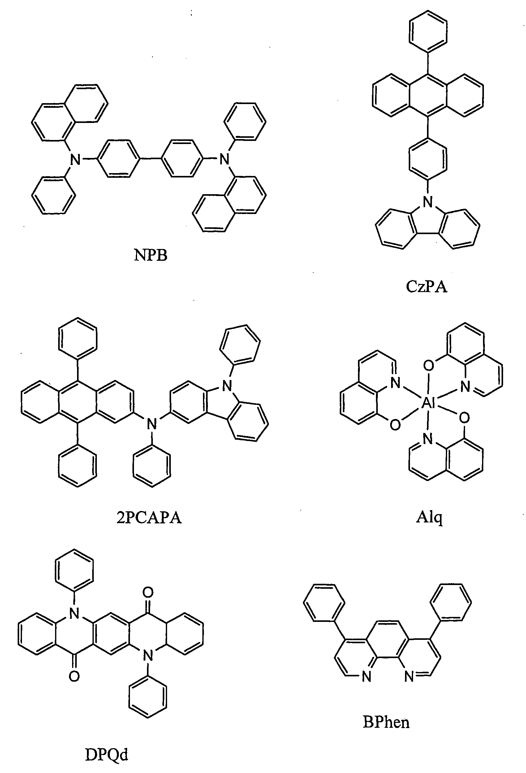
以下,敘述本例子的發光元件的製造方法。 Hereinafter, a method of manufacturing the light-emitting element of this example will be described.
首先,以使形成有像素電極512的面朝下的方式將形成有像素電極512的基板固定於設置在真空蒸鍍裝置中的基板支架。在減壓到10-4Pa左右之後,藉由在像素電極512上共蒸鍍4,4’-雙[N-(1-萘基)-N-苯基氨基]聯苯(簡稱:NPB)和氧化鉬(VI),形成包含複合有機化合物和無機化合物而成的複合材料的第一層2111作為電洞注入層。其厚度為140nm,並將NPB和氧化鉬(VI)的重量比調節為1:0.11(=NPB:氧化鉬)。共蒸鍍法是指在一個處理室中從多個蒸發源同時進行蒸鍍的蒸鍍法。
First, the substrate on which the
接著,藉由使用了電阻加熱的蒸鍍法,在包含複合材料的第一層2111上形成10nm厚的NPB,並形成第二層2112作為電洞傳輸層。
Next, by an evaporation method using resistance heating, NPB was formed to a thickness of 10 nm on the
然後,在第二層2112上共蒸鍍9-[4-(10-苯基-9-蒽基)苯基]-9H-咔唑(簡稱:CzPA)和綠色的發光物質N-(9,10-二苯基-2-蒽基)-N,9-二苯基-9H-咔唑-3-胺(簡稱:2PCAPA),形成第三層2113作為發光層。發光層的厚度為30nm,並將蒸鍍速率調節為使CzPA和2PCAPA的重量比為1:0.05(=CzPA:2PCAPA)。
Then, on the
然後,藉由在第三層2113上共蒸鍍三(8-羥基喹啉合)鋁(簡稱:Alq)和作為電子捕捉性物質的N,N’-二苯基喹吖啶酮(簡稱:DPQd),形成第一電子傳輸區2114a。第一電子傳輸區2114a的厚度為10nm,並將蒸鍍速率調節為使Alq和DPQd的重量比為1:0.005(=Alq:
DPQd)。
Then, by co-evaporating tris(8-hydroxyquinoline) aluminum (abbreviation: Alq) and N,N'-diphenylquinacridone (abbreviation: Alq) as an electron-trapping substance on the
隨後,蒸鍍用作第二電子傳輸區2114b的30nm的紅菲咯啉(簡稱:BPhen),並且形成由第一電子傳輸區2114a和第二電子傳輸區2114b構成的第四層2114作為電子傳輸層。
Subsequently, 30 nm of bathophenanthroline (abbreviation: BPhen) used as the second
此外,藉由在第四層2114上蒸鍍氟化鋰(LiF),形成第五層2115作為電子注入層。第五層2115的厚度為1nm。
Furthermore, by evaporating lithium fluoride (LiF) on the
最後,形成用作陰極的第二電極517。第二電極517由兩層構成。共蒸鍍鋁(Al)和NPB來形成接觸於第五層2115的第一導電層517a。在此,將鋁和NPB的重量比調節為5:1(=Al:NPB)。此外,厚度為100nm。此外,在第一導電層517a上蒸鍍100nm的鋁作為第二導電層517b。須注意第二電極517藉由共同電極層與端子部連接。
Finally, a
此外,在上述蒸鍍過程中,所有蒸鍍都可以使用電阻加熱法。 In addition, in the above-mentioned vapor deposition process, all vapor depositions can use the resistance heating method.
金屬基板401隔著第二黏合劑層400附著於被剝離層116和發光元件518(像素電極512包含在發光元件518中),以防止被剝離層116和發光元件518暴露於大氣。金屬基板401的熱膨脹率大約為10ppm/K,並由20μm厚的鐵素體類不銹鋼基板(Nippon Steel Materials Co.,Ltd所製造,產品名稱:YUS205-M1)構成。第二黏合劑層400由25μm厚的丙烯酸類片狀黏合劑(住友3M公司所
製造,產品名稱:8171J)構成。
The
根據實施例1所說明的製造方法製造本例子所敘述的發光裝置。亦即,首先,在形成在製造基板上的剝離層上形成具有保護膜501和用作第一電極的像素電極512等的被剝離層116。然後,藉由臨時支撐基板將被剝離層116從製造基板轉置到具有對於可見光的透光性和撓性的塑膠基板110。隨後,在像素電極512上形成EL層516和第二電極517來形成發光元件518。最後,使用第二黏合劑層400由金屬基板401密封被剝離層116和發光元件518來製造發光裝置。
The light-emitting device described in this example was manufactured according to the manufacturing method described in Example 1. That is, first, the peeled
在將本例子所敘述的撓性發光裝置捲在直徑10mm的圓柱上,並輸入視頻信號而進行驅動。該發光裝置以彎曲為圓筒狀的狀態回應視頻信號,並進行正常的工作。此外,當將其從圓柱卸下而進行驅動時,其在平面狀態下進行正常的工作。圖9示出發光狀態的照片。 The flexible light-emitting device described in this example was wound on a cylinder with a diameter of 10 mm, and a video signal was input to drive it. The light-emitting device responds to video signals in a state of being bent into a cylinder, and performs normal work. Also, when it is driven detached from the cylinder, it works normally in a flat state. Fig. 9 shows a photo of the light emitting state.
本例子所敘述的發光裝置具有使用耐熱性高的製造基板而製造的被剝離層。結果,可以對被剝離層使用高溫工藝,所以容易形成抗濕性高的保護膜,並且可以確實並廉價地保護發光元件。此外,本例子所敘述的發光裝置具有撓性,因此可以在彎曲的狀態或平面狀態下發光。 The light-emitting device described in this example has a peeled layer manufactured using a highly heat-resistant manufacturing substrate. As a result, a high-temperature process can be used for the peeled layer, so that a protective film with high moisture resistance can be easily formed, and the light-emitting element can be protected reliably and inexpensively. In addition, the light-emitting device described in this example is flexible, so it can emit light in a bent state or a flat state.
本例子中的發光裝置是由薄膜和薄的金屬板構成。因此,不僅重量輕且跌落時的變形少,而且其平面性優良且由於使用環境的變化所引起的彎曲少,所以顯示裝置的驅動電路不容易損壞。由此,所例示的發光裝置適用於撓性 顯示器的用途。 The light emitting device in this example is composed of thin film and thin metal plate. Therefore, not only is it light in weight and less deformed when dropped, but also has excellent planarity and less warpage due to changes in the use environment, so the driving circuit of the display device is less likely to be damaged. Thus, the illustrated light emitting device is suitable for flexible The purpose of the display.
在本例子中,將敘述也可以用作顯示裝置及照明裝置的撓性發光裝置。本例子的發光裝置因為其中不藉由開關元件連接到端子部的多個發光元件的電極層配置為矩陣狀,所以可以說是被動矩陣型,並且可以用作顯示裝置或顯示裝置的背光燈。須注意當不配置多個發光元件而配置一個發光元件時,也可以用作照明裝置。 In this example, a flexible light emitting device that can also be used as a display device and a lighting device will be described. The light emitting device of this example can be said to be a passive matrix type because electrode layers of a plurality of light emitting elements not connected to terminals via switching elements are arranged in a matrix, and can be used as a display device or a backlight for a display device. It should be noted that when one light emitting element is arranged instead of a plurality of light emitting elements, it can also be used as a lighting device.
圖8A和8B指出本例子所敘述的發光裝置的像素部的結構。圖8A是指出被動矩陣型發光裝置的頂視圖,且圖8B是沿著A-A’截斷圖8A的剖面圖。 8A and 8B show the structure of the pixel portion of the light-emitting device described in this example. FIG. 8A is a top view showing a passive matrix type light emitting device, and FIG. 8B is a cross-sectional view of FIG. 8A taken along A-A'.
本例子的撓性發光裝置包括塑膠基板110、被剝離層116、發光元件518和金屬基板401。因為塑膠基板110、發光元件518和金屬基板401是與例子1相同,所以省略其說明。
The flexible light-emitting device of this example includes a
本例子的剝離層116包括保護膜501、像素電極512、層間絕緣膜515a及515b和隔壁519。
The
保護膜501是由200nm厚的氧氮化矽(SiOxNy,x>y)層、200nm厚的氮化矽(SiNy)層、200nm厚的氧氮化矽(SiOxNy,x>y)層、140nm厚的氮氧化矽(SiNyOx,x<y)層、100nm厚的氧氮化矽(SiOxNy,x>y)層的多層膜構成。
The
第一層間絕緣膜515a是由50nm厚的氧氮化矽
(SiOxNy,x>y)層、140nm厚的氮氧化矽(SiNyOx,x<y)層、520nm厚的氧氮化矽(SiOxNy,x>y)層的多層膜構成。
The first
佈線層是使用具有100nm厚的鈦層、700nm厚的鋁層、100nm厚的鈦層的多層膜而形成。此外,第二層間絕緣膜515b是使用具有150nm厚的氧氮化矽(SiOxNy,x>y)層而形成。
The wiring layer was formed using a multilayer film having a 100 nm thick titanium layer, a 700 nm thick aluminum layer, and a 100 nm thick titanium layer. In addition, the second
像素電極512藉由第二層間絕緣膜515b的接觸孔與佈線層電連接。像素電極512是使用具有125nm厚的包含氧化矽的銦錫氧化物(ITSO)膜而形成。
The
此外,像素電極512的端部被由感光聚醯亞胺構成的隔壁519覆蓋。
In addition, the ends of the
在本例子中,在形成在0.7mm厚的玻璃基板上的剝離層上形成被剝離層116。剝離層是使用層疊100nm厚的氧氮化矽(SiOxNy,x>y)層和50nm厚的鎢層的多層膜而形成。
In this example, the peeled
將本例子的撓性發光裝置捲繞在直徑5mm至30mm的圓柱上而進行驅動。當被彎曲成一圓柱形形狀時,該發光裝置發光並正常地操作。此外,當發光裝置從圓柱卸下而進行驅動時,其以平坦形狀正常發光,且即使發光裝置被重複地捲繞在圓柱上且從圓柱卸下,發光裝置也能正常地發光。圖10指出發光狀態的照片。 The flexible light-emitting device of this example is wound around a cylinder with a diameter of 5 mm to 30 mm and driven. When bent into a cylindrical shape, the lighting device emits light and operates normally. In addition, when the light emitting device is detached from the cylinder to be driven, it normally emits light in a flat shape, and even if the light emitting device is repeatedly wound on and detached from the cylinder, the light emitting device can normally emit light. Figure 10 indicates a photo of the light emitting state.
本例子中的發光裝置包括使用耐熱性高的製造基板製造的被剝離層。結果,可以對被剝離層使用高溫處理,所 以容易形成抗濕性高的保護膜,並且可以確實並廉價地保護發光元件。此外,本例子的發光裝置是可撓性的,且可以在彎曲的狀態或平坦狀態下發光。 The light-emitting device in this example includes a peeled layer manufactured using a highly heat-resistant manufacturing substrate. As a result, high temperature treatment can be used on the peeled layer, so It is easy to form a protective film with high moisture resistance, and it is possible to reliably and inexpensively protect light-emitting elements. In addition, the light emitting device of this example is flexible and can emit light in a bent state or a flat state.
本例子的發光裝置是由薄膜和薄的金屬板構成。由於發光裝置是薄的,因此可以藉著沿一彎曲表面而被變形,使發光裝置放置於窄的地方。此外,發光裝置是重量輕的,所以可以適用於對重量有嚴格要求的裝置例如可擕式設備及飛機等。 The light-emitting device of this example is composed of a thin film and a thin metal plate. Since the light emitting device is thin, it can be deformed along a curved surface so that the light emitting device can be placed in a narrow place. In addition, the light-emitting device is light in weight, so it can be applied to devices with strict weight requirements such as portable devices and airplanes.
本發明係根據2008年10月16日在日本專利局申請的日本專利申請案號2008-267774,及2009年5月21日在日本專利局申請的日本專利申請案號2009-123451而製作,其整體內容亦併入本案中作為參考。 The present invention is made according to Japanese Patent Application No. 2008-267774 filed at the Japan Patent Office on October 16, 2008, and Japanese Patent Application No. 2009-123451 filed at the Japan Patent Office on May 21, 2009. The entire content is also incorporated into this case by reference.
110:塑膠基板 110: Plastic substrate
111:黏合劑層 111: Adhesive layer
112:保護膜 112: Protective film
113:基底絕緣膜 113: base insulating film
114:像素TFT 114: pixel TFT
115:TFT 115:TFT
116:被剝離層 116: stripped layer
117:第一電極 117: first electrode
118:分隔壁 118: partition wall
119:EL層 119:EL layer
120:第二電極 120: second electrode
121:黏合劑層 121: Adhesive layer
122:金屬基板 122: metal substrate
123:樹脂層 123: resin layer
124:塗敷膜 124: coating film
125:保護膜 125: Protective film
126:膜密封層 126: Membrane sealing layer
127:發光元件 127: Light emitting element
128:第一層間絕緣膜 128: The first interlayer insulating film
129:第二層間絕緣膜 129: Second interlayer insulating film
Claims (5)
Applications Claiming Priority (4)
| Application Number | Priority Date | Filing Date | Title |
|---|---|---|---|
| JP2008267774 | 2008-10-16 | ||
| JP2008-267774 | 2008-10-16 | ||
| JP2009-123451 | 2009-05-21 | ||
| JP2009123451 | 2009-05-21 |
Publications (2)
| Publication Number | Publication Date |
|---|---|
| TW202119866A TW202119866A (en) | 2021-05-16 |
| TWI792062B true TWI792062B (en) | 2023-02-11 |
Family
ID=41647038
Family Applications (5)
| Application Number | Title | Priority Date | Filing Date |
|---|---|---|---|
| TW105137897A TWI624191B (en) | 2008-10-16 | 2009-10-13 | Flexible light-emitting device, electronic device, and method for manufacturing flexible-light emitting device |
| TW104122036A TWI573490B (en) | 2008-10-16 | 2009-10-13 | Flexible light-emitting device, electronic device, and manufacturing method of flexible light-emitting device |
| TW098134618A TWI503042B (en) | 2008-10-16 | 2009-10-13 | Flexible light-emitting device, electronic device, and manufacturing method of flexible light-emitting device |
| TW107106238A TWI708522B (en) | 2008-10-16 | 2009-10-13 | Light-emitting device |
| TW109134122A TWI792062B (en) | 2008-10-16 | 2009-10-13 | Light-emitting device |
Family Applications Before (4)
| Application Number | Title | Priority Date | Filing Date |
|---|---|---|---|
| TW105137897A TWI624191B (en) | 2008-10-16 | 2009-10-13 | Flexible light-emitting device, electronic device, and method for manufacturing flexible-light emitting device |
| TW104122036A TWI573490B (en) | 2008-10-16 | 2009-10-13 | Flexible light-emitting device, electronic device, and manufacturing method of flexible light-emitting device |
| TW098134618A TWI503042B (en) | 2008-10-16 | 2009-10-13 | Flexible light-emitting device, electronic device, and manufacturing method of flexible light-emitting device |
| TW107106238A TWI708522B (en) | 2008-10-16 | 2009-10-13 | Light-emitting device |
Country Status (6)
| Country | Link |
|---|---|
| US (9) | US8188474B2 (en) |
| EP (1) | EP2178133B1 (en) |
| JP (12) | JP2011003522A (en) |
| KR (9) | KR101691385B1 (en) |
| CN (1) | CN101728420B (en) |
| TW (5) | TWI624191B (en) |
Families Citing this family (116)
| Publication number | Priority date | Publication date | Assignee | Title |
|---|---|---|---|---|
| JP2011003522A (en) | 2008-10-16 | 2011-01-06 | Semiconductor Energy Lab Co Ltd | Flexible light-emitting device, electronic equipment, and method of manufacturing flexible light-emitting device |
| US8610155B2 (en) | 2008-11-18 | 2013-12-17 | Semiconductor Energy Laboratory Co., Ltd. | Light-emitting device, method for manufacturing the same, and cellular phone |
| TWI654754B (en) | 2008-11-28 | 2019-03-21 | 日商半導體能源研究所股份有限公司 | Liquid crystal display device |
| US8576209B2 (en) | 2009-07-07 | 2013-11-05 | Semiconductor Energy Laboratory Co., Ltd. | Display device |
| JP5642447B2 (en) * | 2009-08-07 | 2014-12-17 | 株式会社半導体エネルギー研究所 | Semiconductor device |
| KR102480780B1 (en) | 2009-09-16 | 2022-12-22 | 가부시키가이샤 한도오따이 에네루기 켄큐쇼 | Light-emitting device and manufacturing method thereof |
| KR101730347B1 (en) * | 2009-09-16 | 2017-04-27 | 가부시키가이샤 한도오따이 에네루기 켄큐쇼 | Semiconductor device and manufacturing method thereof |
| US8716699B2 (en) * | 2009-10-29 | 2014-05-06 | E I Du Pont De Nemours And Company | Organic light-emitting diodes having white light emission |
| US8716700B2 (en) | 2009-10-29 | 2014-05-06 | E I Du Pont De Nemours And Company | Organic light-emitting diodes having white light emission |
| KR101125570B1 (en) * | 2009-12-04 | 2012-03-22 | 삼성모바일디스플레이주식회사 | Organic light emitting diode device |
| TWI589042B (en) * | 2010-01-20 | 2017-06-21 | 半導體能源研究所股份有限公司 | Light emitting device, flexible light emitting device, electronic device, lighting device, and manufacturing method of light emitting device and flexible light emitting device |
| US9000442B2 (en) * | 2010-01-20 | 2015-04-07 | Semiconductor Energy Laboratory Co., Ltd. | Light-emitting device, flexible light-emitting device, electronic device, and method for manufacturing light-emitting device and flexible-light emitting device |
| US8569793B2 (en) * | 2010-04-01 | 2013-10-29 | National Tsing Hua University | Organic light-emitting diode with high color rendering |
| US8647919B2 (en) * | 2010-09-13 | 2014-02-11 | Semiconductor Energy Laboratory Co., Ltd. | Light-emitting display device and method for manufacturing the same |
| US8476622B2 (en) * | 2011-01-05 | 2013-07-02 | Electronics And Telecommunications Research Institute | Active matrix organic light emitting diode |
| KR102010429B1 (en) * | 2011-02-25 | 2019-08-13 | 가부시키가이샤 한도오따이 에네루기 켄큐쇼 | Light-emitting device and electronic device using light-emitting device |
| KR20120102001A (en) * | 2011-03-07 | 2012-09-17 | 가부시키가이샤 한도오따이 에네루기 켄큐쇼 | Light-emitting element and light-emitting device |
| JP5355618B2 (en) | 2011-03-10 | 2013-11-27 | 三星ディスプレイ株式會社 | Flexible display device and manufacturing method thereof |
| JP4976595B1 (en) * | 2011-03-11 | 2012-07-18 | パイオニア株式会社 | Organic electroluminescence device |
| KR101917752B1 (en) * | 2011-05-11 | 2018-11-13 | 가부시키가이샤 한도오따이 에네루기 켄큐쇼 | Light-emitting element, light-emitting module, light-emmiting panel, and light-emitting device |
| KR101320384B1 (en) | 2011-06-30 | 2013-10-23 | 삼성디스플레이 주식회사 | Flexible display panel and the display apparatus comprising the flexible display panel |
| WO2013008765A1 (en) * | 2011-07-08 | 2013-01-17 | Semiconductor Energy Laboratory Co., Ltd. | Light-emitting module, light-emitting device, and method for manufacturing the light-emitting module |
| JP4982620B1 (en) * | 2011-07-29 | 2012-07-25 | 富士フイルム株式会社 | Manufacturing method of field effect transistor, field effect transistor, display device, image sensor, and X-ray sensor |
| JP2013045522A (en) * | 2011-08-22 | 2013-03-04 | Sony Corp | Display device and manufacturing method therefor |
| KR101862676B1 (en) * | 2011-10-06 | 2018-06-01 | 삼성디스플레이 주식회사 | Organic light emitting display device |
| US10446629B2 (en) | 2011-10-14 | 2019-10-15 | Diftek Lasers, Inc. | Electronic device and method of making thereof |
| CN102386329B (en) * | 2011-11-14 | 2014-04-30 | 中山大学 | Manufacturing method of flexible electronic device |
| CN102496684B (en) * | 2011-12-27 | 2015-08-26 | 昆山龙腾光电有限公司 | Flexible display |
| JP2013251255A (en) * | 2012-05-04 | 2013-12-12 | Semiconductor Energy Lab Co Ltd | Method for manufacturing light-emitting device |
| KR102079188B1 (en) | 2012-05-09 | 2020-02-19 | 가부시키가이샤 한도오따이 에네루기 켄큐쇼 | Light-emitting device and electronic device |
| KR102082793B1 (en) | 2012-05-10 | 2020-02-28 | 가부시키가이샤 한도오따이 에네루기 켄큐쇼 | Display device and method for manufacturing the same |
| KR101386219B1 (en) | 2012-06-26 | 2014-04-17 | 삼성디스플레이 주식회사 | Flexible display panel, display device comprising the panel and method thereof |
| US9184211B2 (en) | 2012-07-05 | 2015-11-10 | Semiconductor Energy Laboratory Co., Ltd. | Light-emitting device and method for fabricating the same |
| US9673014B2 (en) * | 2012-07-13 | 2017-06-06 | Samsung Display Co., Ltd. | Method of manufacturing display panel |
| US20150162566A1 (en) * | 2012-07-27 | 2015-06-11 | Konica Minolta, Inc. | Organic electroluminescent element |
| JP6296187B2 (en) * | 2012-07-31 | 2018-03-20 | 株式会社Joled | Display device and electronic device |
| KR20140021096A (en) * | 2012-08-07 | 2014-02-20 | 한국전자통신연구원 | Self-aligned thin film transistor with doping barrier and manufacturing method thereof |
| KR102703850B1 (en) | 2012-08-10 | 2024-09-09 | 가부시키가이샤 한도오따이 에네루기 켄큐쇼 | Light-emitting device |
| US20140061610A1 (en) | 2012-08-31 | 2014-03-06 | Hyo-Young MUN | Organic light emitting device and manufacturing method thereof |
| KR101578266B1 (en) * | 2013-03-12 | 2015-12-16 | 박진성 | Wafer Level Chip Scale Light Emitting Diode Package |
| JP6490901B2 (en) | 2013-03-14 | 2019-03-27 | 株式会社半導体エネルギー研究所 | Method for manufacturing light emitting device |
| US9209207B2 (en) * | 2013-04-09 | 2015-12-08 | Apple Inc. | Flexible display with bent edge regions |
| TWI692108B (en) * | 2013-04-10 | 2020-04-21 | 日商半導體能源研究所股份有限公司 | Semiconductor device and manufacturing method thereof |
| TW201445794A (en) * | 2013-05-27 | 2014-12-01 | Wistron Corp | Package structure of organic optic-electro device and method for packaging thereof |
| KR102090713B1 (en) * | 2013-06-25 | 2020-03-19 | 삼성디스플레이 주식회사 | flexible display panel and the display apparatus comprising the flexible display panel |
| TWI532162B (en) | 2013-06-25 | 2016-05-01 | 友達光電股份有限公司 | Flexible display panel and method of manufacturing same |
| KR101429095B1 (en) * | 2013-07-09 | 2014-08-12 | 피에스아이 주식회사 | LED lamps with nano-scale LED electrode assembly |
| KR102059167B1 (en) * | 2013-07-30 | 2020-02-07 | 엘지디스플레이 주식회사 | Flexible Organic Electroluminescence Device and Method for fabricating of the same |
| KR102127791B1 (en) * | 2013-07-31 | 2020-06-30 | 삼성디스플레이 주식회사 | Flexible display device |
| CN103400850B (en) * | 2013-08-14 | 2016-01-20 | 中国科学院长春光学精密机械与物理研究所 | For flexible led array device and the manufacture method of micro-display and illumination |
| JP6286941B2 (en) | 2013-08-27 | 2018-03-07 | セイコーエプソン株式会社 | LIGHT EMITTING DEVICE, LIGHT EMITTING DEVICE MANUFACTURING METHOD, ELECTRONIC DEVICE |
| CN105473577B (en) * | 2013-08-29 | 2019-05-14 | 株式会社半导体能源研究所 | Heterocyclic compound, light-emitting element, light-emitting device, electronic equipment, and lighting device |
| TWI705861B (en) * | 2013-08-30 | 2020-10-01 | 日商半導體能源研究所股份有限公司 | Support supply apparatus and method for supplying support |
| JP2015072770A (en) * | 2013-10-02 | 2015-04-16 | 株式会社ジャパンディスプレイ | Organic electroluminescent device and method for manufacturing the same |
| US9430180B2 (en) | 2013-11-15 | 2016-08-30 | Semiconductor Energy Laboratory Co., Ltd | Display panel and electronic device |
| KR102315659B1 (en) | 2013-11-27 | 2021-10-20 | 가부시키가이샤 한도오따이 에네루기 켄큐쇼 | Display device |
| CN110676395A (en) * | 2013-12-02 | 2020-01-10 | 株式会社半导体能源研究所 | Display device and method of manufacturing the same |
| KR102132697B1 (en) | 2013-12-05 | 2020-07-10 | 엘지디스플레이 주식회사 | Curved Display Device |
| JP2015122148A (en) * | 2013-12-20 | 2015-07-02 | 株式会社ジャパンディスプレイ | Organic electroluminescence display device |
| KR20150075367A (en) * | 2013-12-25 | 2015-07-03 | 가부시키가이샤 한도오따이 에네루기 켄큐쇼 | Display device and electronic device |
| KR102347532B1 (en) | 2014-01-23 | 2022-01-05 | 삼성디스플레이 주식회사 | Flexible display apparatus and method of manufacturing thereof |
| KR102334815B1 (en) | 2014-02-19 | 2021-12-02 | 가부시키가이샤 한도오따이 에네루기 켄큐쇼 | Light-emitting device and peeling method |
| US9899626B2 (en) * | 2014-03-06 | 2018-02-20 | Semiconductor Energy Laboratory Co., Ltd. | Light-emitting device |
| US9660004B2 (en) * | 2014-03-21 | 2017-05-23 | Apple Inc. | Flexible displays with strengthened pad area |
| TWI831924B (en) | 2014-04-25 | 2024-02-11 | 日商半導體能源研究所股份有限公司 | Display device and electronic device |
| JP6399801B2 (en) * | 2014-05-13 | 2018-10-03 | 株式会社ジャパンディスプレイ | Organic electroluminescence display device |
| TWI726843B (en) * | 2014-05-30 | 2021-05-11 | 日商半導體能源研究所股份有限公司 | Touch panel |
| JP6727762B2 (en) * | 2014-05-30 | 2020-07-22 | 株式会社半導体エネルギー研究所 | Light emitting device and electronic device |
| JP2016085969A (en) * | 2014-10-24 | 2016-05-19 | 株式会社半導体エネルギー研究所 | LIGHT EMITTING ELEMENT, LIGHT EMITTING DEVICE, ELECTRONIC DEVICE, AND LIGHTING DEVICE |
| JP6674764B2 (en) * | 2014-12-01 | 2020-04-01 | 株式会社半導体エネルギー研究所 | Method for manufacturing display panel |
| JP6595317B2 (en) * | 2014-12-01 | 2019-10-23 | 株式会社半導体エネルギー研究所 | Display device |
| KR102439040B1 (en) * | 2014-12-01 | 2022-09-01 | 엘지디스플레이 주식회사 | Organic light emitting display device and rollable organic light emitting display system including same |
| KR20160068672A (en) * | 2014-12-05 | 2016-06-15 | 동우 화인켐 주식회사 | Flexible substrate and preparing method thereof |
| CN104538420A (en) * | 2014-12-12 | 2015-04-22 | 深圳市华星光电技术有限公司 | Flexible oled display device and manufacturing method thereof |
| JP6432343B2 (en) * | 2014-12-26 | 2018-12-05 | 日亜化学工業株式会社 | Method for manufacturing light emitting device |
| CN104485351A (en) * | 2014-12-31 | 2015-04-01 | 深圳市华星光电技术有限公司 | Flexible organic light-emitting display and manufacturing method thereof |
| JP2017004642A (en) * | 2015-06-05 | 2017-01-05 | 双葉電子工業株式会社 | Flexible organic EL device |
| JP2017009725A (en) * | 2015-06-19 | 2017-01-12 | ソニー株式会社 | Display device |
| KR102288354B1 (en) * | 2015-08-10 | 2021-08-11 | 삼성디스플레이 주식회사 | Method for manufacturing flexible display apparatus |
| CN105182652A (en) * | 2015-09-25 | 2015-12-23 | 京东方科技集团股份有限公司 | Pixel separating wall, display substrate and manufacturing method thereof and display device |
| TWI577251B (en) * | 2015-12-01 | 2017-04-01 | 同泰電子科技股份有限公司 | Rigid-flex circuit board and manufacturing method thereof |
| US10312310B2 (en) * | 2016-01-19 | 2019-06-04 | Diftek Lasers, Inc. | OLED display and method of fabrication thereof |
| US10590600B1 (en) * | 2016-01-19 | 2020-03-17 | Apple Inc. | Illumination systems within fabric-based devices |
| CN105720062B (en) * | 2016-02-02 | 2018-11-06 | 京东方科技集团股份有限公司 | The flexible base board and preparation method thereof of bent display device |
| KR102340066B1 (en) * | 2016-04-07 | 2021-12-15 | 가부시키가이샤 한도오따이 에네루기 켄큐쇼 | Peeling method and manufacturing method of flexible device |
| CN106371664B (en) * | 2016-08-31 | 2020-03-24 | 绍兴市梓昂新材料有限公司 | Preparation method of flexible nano touch film |
| US10528198B2 (en) | 2016-09-16 | 2020-01-07 | Semiconductor Energy Laboratory Co., Ltd. | Display panel, display device, input/output device, data processing device, and method for manufacturing the display panel |
| US10593657B2 (en) * | 2016-11-01 | 2020-03-17 | Innolux Corporation | Display devices and methods for forming the same |
| JP6890003B2 (en) * | 2016-11-29 | 2021-06-18 | 株式会社ジャパンディスプレイ | Display device |
| JP6887799B2 (en) * | 2016-12-26 | 2021-06-16 | 株式会社ジャパンディスプレイ | Display device |
| KR102597750B1 (en) * | 2016-12-28 | 2023-11-07 | 엘지디스플레이 주식회사 | Flexible display |
| KR102646618B1 (en) * | 2017-01-11 | 2024-03-12 | 삼성디스플레이 주식회사 | Display device and manufacturing method of the same |
| KR102561983B1 (en) * | 2017-03-16 | 2023-08-01 | 가부시키가이샤 한도오따이 에네루기 켄큐쇼 | Manufacturing method of semiconductor device and semiconductor device |
| WO2018179266A1 (en) * | 2017-03-30 | 2018-10-04 | シャープ株式会社 | Method for manufacturing el device and apparatus for manufacturing el device |
| CN107104200A (en) * | 2017-04-27 | 2017-08-29 | 上海天马微电子有限公司 | Flexible display panel and flexible display device |
| CN107123666A (en) * | 2017-05-27 | 2017-09-01 | 上海天马微电子有限公司 | Display panel and display device |
| JP6935244B2 (en) * | 2017-06-27 | 2021-09-15 | 株式会社ジャパンディスプレイ | Display device and manufacturing method of display device |
| KR102349279B1 (en) * | 2017-09-08 | 2022-01-11 | 삼성디스플레이 주식회사 | Display device |
| JP6562054B2 (en) * | 2017-10-02 | 2019-08-21 | セイコーエプソン株式会社 | LIGHT EMITTING DEVICE AND ELECTRONIC DEVICE |
| KR102448325B1 (en) * | 2017-11-16 | 2022-09-30 | 삼성디스플레이 주식회사 | Display panel and electronic device including same |
| JP2019102153A (en) * | 2017-11-29 | 2019-06-24 | 株式会社ジャパンディスプレイ | Light emitting device and display device |
| KR102546170B1 (en) | 2018-01-19 | 2023-06-22 | 삼성디스플레이 주식회사 | Display device |
| US10879195B2 (en) * | 2018-02-15 | 2020-12-29 | Micron Technology, Inc. | Method for substrate moisture NCF voiding elimination |
| CN109713164A (en) * | 2018-12-29 | 2019-05-03 | 武汉天马微电子有限公司 | Display panel and display device |
| CN109801953B (en) * | 2019-02-15 | 2021-02-26 | 京东方科技集团股份有限公司 | Organic light emitting diode display substrate, and preparation method and device thereof |
| TWI706205B (en) * | 2019-02-19 | 2020-10-01 | 陳冠宇 | Organic light emitting display device |
| CN110021714A (en) * | 2019-04-15 | 2019-07-16 | 湖畔光电科技(江苏)有限公司 | A kind of production technology of OLED minitype displayer transparent cathode |
| US12029100B2 (en) * | 2019-04-19 | 2024-07-02 | Sharp Kabushiki Kaisha | Method for manufacturing display device |
| JP2021005469A (en) * | 2019-06-25 | 2021-01-14 | 住友化学株式会社 | Manufacturing method of organic electronic device |
| CN111341812B (en) * | 2020-03-10 | 2022-07-29 | 京东方科技集团股份有限公司 | Display substrate, preparation method thereof and display device |
| CN113570844B (en) * | 2020-04-28 | 2022-09-09 | 清华大学 | Laser remote control switch system |
| KR102826508B1 (en) * | 2020-06-02 | 2025-06-27 | 삼성디스플레이 주식회사 | Display device and manufacturing method thereof |
| EP4141972A4 (en) * | 2020-06-08 | 2024-05-01 | Seoul Viosys Co., Ltd | UNIT PIXEL WITH LIGHT-EMITTING DEVICES AND DISPLAY DEVICE |
| US12364073B2 (en) | 2020-06-08 | 2025-07-15 | Seoul Viosys Co., Ltd. | Unit pixel having light emitting device and displaying apparatus |
| KR20220048506A (en) * | 2020-10-12 | 2022-04-20 | 삼성디스플레이 주식회사 | Display device |
| CN112786802A (en) * | 2020-12-23 | 2021-05-11 | 乐金显示光电科技(中国)有限公司 | Display device packaging structure and manufacturing method of packaging plate |
Citations (4)
| Publication number | Priority date | Publication date | Assignee | Title |
|---|---|---|---|---|
| JP2001313164A (en) * | 2000-04-28 | 2001-11-09 | Matsushita Electric Ind Co Ltd | Organic electroluminescence element, display device and mobile terminal using the same |
| TW200534746A (en) * | 2004-03-26 | 2005-10-16 | Matsushita Electric Works Ltd | Organic light emitting element |
| JP2007250239A (en) * | 2006-03-14 | 2007-09-27 | Konica Minolta Holdings Inc | Organic electroluminescence element, and organic electroluminescence display |
| US20080238302A1 (en) * | 2007-03-28 | 2008-10-02 | Samsung Electronics Co., Ltd. | Display device and method for manufacturing the same |
Family Cites Families (223)
| Publication number | Priority date | Publication date | Assignee | Title |
|---|---|---|---|---|
| JPS5944453B2 (en) | 1980-12-03 | 1984-10-30 | 五洋建設株式会社 | Sand column creation device for soft ground improvement |
| JPS60154730U (en) | 1984-03-26 | 1985-10-15 | 株式会社クボタ | Equipment for removing deposits inside the ash chute in an incinerator |
| JPS6330015A (en) | 1986-07-23 | 1988-02-08 | Hitachi Ltd | Surface acoustic wave delay device |
| JPS63170892A (en) | 1987-01-07 | 1988-07-14 | アルプス電気株式会社 | Thin film el device |
| JP2742057B2 (en) | 1988-07-14 | 1998-04-22 | シャープ株式会社 | Thin film EL panel |
| JPH02106858A (en) | 1988-10-14 | 1990-04-18 | Nec Corp | Cathode-ray tube |
| US5189405A (en) | 1989-01-26 | 1993-02-23 | Sharp Kabushiki Kaisha | Thin film electroluminescent panel |
| JPH0329291A (en) | 1989-06-27 | 1991-02-07 | Sumitomo Bakelite Co Ltd | Water-trapping film for organic dispersed EL lamps |
| JPH03238792A (en) * | 1990-02-16 | 1991-10-24 | Nitto Denko Corp | Electro-luminescence light emitting apparatus |
| JPH06330015A (en) | 1993-05-20 | 1994-11-29 | Nissan Motor Co Ltd | Adhesive resin composition |
| JP3293736B2 (en) | 1996-02-28 | 2002-06-17 | キヤノン株式会社 | Semiconductor substrate manufacturing method and bonded substrate |
| US5771562A (en) | 1995-05-02 | 1998-06-30 | Motorola, Inc. | Passivation of organic devices |
| US5811177A (en) | 1995-11-30 | 1998-09-22 | Motorola, Inc. | Passivation of electroluminescent organic devices |
| US5686360A (en) | 1995-11-30 | 1997-11-11 | Motorola | Passivation of organic devices |
| US6008506A (en) * | 1996-04-25 | 1999-12-28 | Nec Corporation | SOI optical semiconductor device |
| US5693956A (en) | 1996-07-29 | 1997-12-02 | Motorola | Inverted oleds on hard plastic substrate |
| EP0858110B1 (en) | 1996-08-27 | 2006-12-13 | Seiko Epson Corporation | Separating method, method for transferring thin film device, and liquid crystal display device manufactured by using the transferring method |
| US5789859A (en) * | 1996-11-25 | 1998-08-04 | Micron Display Technology, Inc. | Field emission display with non-evaporable getter material |
| US5952778A (en) | 1997-03-18 | 1999-09-14 | International Business Machines Corporation | Encapsulated organic light emitting device |
| JP3290375B2 (en) | 1997-05-12 | 2002-06-10 | 松下電器産業株式会社 | Organic electroluminescent device |
| JPH1126733A (en) | 1997-07-03 | 1999-01-29 | Seiko Epson Corp | Transfer method of thin film device, thin film device, thin film integrated circuit device, active matrix substrate, liquid crystal display device, and electronic equipment |
| US6198220B1 (en) | 1997-07-11 | 2001-03-06 | Emagin Corporation | Sealing structure for organic light emitting devices |
| JPH1173148A (en) | 1997-08-27 | 1999-03-16 | Pioneer Electron Corp | Light emitting display device and its production |
| KR100249784B1 (en) | 1997-11-20 | 2000-04-01 | 정선종 | Packaging method of organic or polymer electroluminescent device using polymer composite membrane |
| US6157426A (en) * | 1998-02-13 | 2000-12-05 | Ois Optical Imaging Systems, Inc. | Liquid crystal display with SiOx Ny inclusive multilayer black matrix |
| US6008872A (en) * | 1998-03-13 | 1999-12-28 | Ois Optical Imaging Systems, Inc. | High aperture liquid crystal display including thin film diodes, and method of making same |
| US6200734B1 (en) * | 1998-06-15 | 2001-03-13 | Lucent Technologies Inc. | Method for fabricating semiconductor devices |
| JP3039517B2 (en) * | 1998-06-19 | 2000-05-08 | 日本電気株式会社 | Active matrix liquid crystal display |
| US6146225A (en) | 1998-07-30 | 2000-11-14 | Agilent Technologies, Inc. | Transparent, flexible permeability barrier for organic electroluminescent devices |
| US6097041A (en) * | 1998-08-24 | 2000-08-01 | Kingmax Technology Inc. | Light-emitting diode with anti-reflector |
| US6268695B1 (en) | 1998-12-16 | 2001-07-31 | Battelle Memorial Institute | Environmental barrier material for organic light emitting device and method of making |
| US6153541A (en) * | 1999-02-23 | 2000-11-28 | Vanguard International Semiconductor Corporation | Method for fabricating an oxynitride layer having anti-reflective properties and low leakage current |
| EP1041624A1 (en) | 1999-04-02 | 2000-10-04 | Interuniversitair Microelektronica Centrum Vzw | Method of transferring ultra-thin substrates and application of the method to the manufacture of a multilayer thin film device |
| US6461899B1 (en) * | 1999-04-30 | 2002-10-08 | Semiconductor Energy Laboratory, Co., Ltd. | Oxynitride laminate “blocking layer” for thin film semiconductor devices |
| TW517260B (en) * | 1999-05-15 | 2003-01-11 | Semiconductor Energy Lab | Semiconductor device and method for its fabrication |
| GB9915648D0 (en) | 1999-07-06 | 1999-09-01 | Rolls Royce Plc | Improvement in or relating to turbine blades |
| JP3942770B2 (en) | 1999-09-22 | 2007-07-11 | 株式会社半導体エネルギー研究所 | EL display device and electronic device |
| US6413645B1 (en) | 2000-04-20 | 2002-07-02 | Battelle Memorial Institute | Ultrabarrier substrates |
| JP4562835B2 (en) * | 1999-11-05 | 2010-10-13 | 株式会社半導体エネルギー研究所 | Method for manufacturing semiconductor device |
| JP2001175198A (en) | 1999-12-14 | 2001-06-29 | Semiconductor Energy Lab Co Ltd | Semiconductor device and manufacturing method thereof |
| TWI252592B (en) | 2000-01-17 | 2006-04-01 | Semiconductor Energy Lab | EL display device |
| US7060153B2 (en) * | 2000-01-17 | 2006-06-13 | Semiconductor Energy Laboratory Co., Ltd. | Display device and method of manufacturing the same |
| US20010053559A1 (en) * | 2000-01-25 | 2001-12-20 | Semiconductor Energy Laboratory Co., Ltd. | Method of fabricating display device |
| TW494447B (en) * | 2000-02-01 | 2002-07-11 | Semiconductor Energy Lab | Semiconductor device and manufacturing method thereof |
| JP3862466B2 (en) | 2000-02-29 | 2006-12-27 | 三井化学株式会社 | Transparent electrode |
| TW507258B (en) * | 2000-02-29 | 2002-10-21 | Semiconductor Systems Corp | Display device and method for fabricating the same |
| US6882102B2 (en) * | 2000-02-29 | 2005-04-19 | Semiconductor Energy Laboratory Co., Ltd. | Light emitting device and manufacturing method thereof |
| US6492026B1 (en) | 2000-04-20 | 2002-12-10 | Battelle Memorial Institute | Smoothing and barrier layers on high Tg substrates |
| US7579203B2 (en) * | 2000-04-25 | 2009-08-25 | Semiconductor Energy Laboratory Co., Ltd. | Light emitting device |
| KR100386611B1 (en) * | 2000-05-08 | 2003-06-02 | 주식회사 하이닉스반도체 | A array of flash memory cell and method for programming of data thereby and method for erased thereby |
| TW501282B (en) * | 2000-06-07 | 2002-09-01 | Semiconductor Energy Lab | Method of manufacturing semiconductor device |
| JP2002015858A (en) | 2000-06-30 | 2002-01-18 | Sony Corp | Electroluminescence display device |
| JP4626018B2 (en) | 2000-06-30 | 2011-02-02 | ソニー株式会社 | Organic electroluminescence display device |
| JP4747401B2 (en) * | 2000-08-07 | 2011-08-17 | 凸版印刷株式会社 | Organic electroluminescence device and method for manufacturing the same |
| US6825820B2 (en) | 2000-08-10 | 2004-11-30 | Semiconductor Energy Laboratory Co., Ltd. | Display device and electronic device |
| JP4906022B2 (en) * | 2000-08-10 | 2012-03-28 | 株式会社半導体エネルギー研究所 | Active matrix EL display device and electronic device |
| US7178927B2 (en) | 2000-11-14 | 2007-02-20 | Semiconductor Energy Laboratory Co., Ltd. | Electroluminescent device having drying agent |
| JP4507395B2 (en) | 2000-11-30 | 2010-07-21 | セイコーエプソン株式会社 | Method for manufacturing element substrate for electro-optical device |
| US6583440B2 (en) | 2000-11-30 | 2003-06-24 | Seiko Epson Corporation | Soi substrate, element substrate, semiconductor device, electro-optical apparatus, electronic equipment, method of manufacturing the soi substrate, method of manufacturing the element substrate, and method of manufacturing the electro-optical apparatus |
| US6881447B2 (en) * | 2002-04-04 | 2005-04-19 | Dielectric Systems, Inc. | Chemically and electrically stabilized polymer films |
| JP4831885B2 (en) * | 2001-04-27 | 2011-12-07 | 株式会社半導体エネルギー研究所 | Method for manufacturing semiconductor device |
| JP2003086356A (en) | 2001-09-06 | 2003-03-20 | Semiconductor Energy Lab Co Ltd | Light emitting device and electronic device |
| TW548860B (en) | 2001-06-20 | 2003-08-21 | Semiconductor Energy Lab | Light emitting device and method of manufacturing the same |
| US7211828B2 (en) | 2001-06-20 | 2007-05-01 | Semiconductor Energy Laboratory Co., Ltd. | Light emitting device and electronic apparatus |
| US6475857B1 (en) * | 2001-06-21 | 2002-11-05 | Samsung Electronics Co., Ltd. | Method of making a scalable two transistor memory device |
| TW546857B (en) * | 2001-07-03 | 2003-08-11 | Semiconductor Energy Lab | Light-emitting device, method of manufacturing a light-emitting device, and electronic equipment |
| US6982178B2 (en) | 2002-06-10 | 2006-01-03 | E Ink Corporation | Components and methods for use in electro-optic displays |
| TW564471B (en) | 2001-07-16 | 2003-12-01 | Semiconductor Energy Lab | Semiconductor device and peeling off method and method of manufacturing semiconductor device |
| JP4027740B2 (en) | 2001-07-16 | 2007-12-26 | 株式会社半導体エネルギー研究所 | Method for manufacturing semiconductor device |
| JP2003109773A (en) * | 2001-07-27 | 2003-04-11 | Semiconductor Energy Lab Co Ltd | Light emitting device, semiconductor device, and manufacturing method thereof |
| KR20030011986A (en) | 2001-07-30 | 2003-02-12 | 엘지.필립스 엘시디 주식회사 | The organic electro-luminescence device |
| US7351300B2 (en) * | 2001-08-22 | 2008-04-01 | Semiconductor Energy Laboratory Co., Ltd. | Peeling method and method of manufacturing semiconductor device |
| US6653053B2 (en) * | 2001-08-27 | 2003-11-25 | Motorola, Inc. | Method of forming a pattern on a semiconductor wafer using an attenuated phase shifting reflective mask |
| JP2003203925A (en) | 2001-10-26 | 2003-07-18 | Semiconductor Energy Lab Co Ltd | Semiconductor device and manufacturing method therefor |
| TW594947B (en) | 2001-10-30 | 2004-06-21 | Semiconductor Energy Lab | Semiconductor device and method of manufacturing the same |
| TWI264121B (en) * | 2001-11-30 | 2006-10-11 | Semiconductor Energy Lab | A display device, a method of manufacturing a semiconductor device, and a method of manufacturing a display device |
| JP2003229548A (en) | 2001-11-30 | 2003-08-15 | Semiconductor Energy Lab Co Ltd | Vehicle, display device and method for manufacturing semiconductor device |
| US7050835B2 (en) | 2001-12-12 | 2006-05-23 | Universal Display Corporation | Intelligent multi-media display communication system |
| JP4563031B2 (en) | 2001-12-12 | 2010-10-13 | ユニバーサル ディスプレイ コーポレイション | Multimedia display communication system with information processing function |
| KR20040066898A (en) | 2001-12-13 | 2004-07-27 | 코닌클리케 필립스 일렉트로닉스 엔.브이. | Sealing structure for display devices |
| US6815723B2 (en) * | 2001-12-28 | 2004-11-09 | Semiconductor Energy Laboratory Co., Ltd. | Light emitting device, method of manufacturing the same, and manufacturing apparatus therefor |
| US6835954B2 (en) | 2001-12-29 | 2004-12-28 | Lg.Philips Lcd Co., Ltd. | Active matrix organic electroluminescent display device |
| KR100484591B1 (en) | 2001-12-29 | 2005-04-20 | 엘지.필립스 엘시디 주식회사 | an active matrix organic electroluminescence display and a manufacturing method of the same |
| US6933520B2 (en) | 2002-02-13 | 2005-08-23 | Semiconductor Energy Laboratory Co., Ltd. | Light emitting device |
| JP3942017B2 (en) | 2002-03-25 | 2007-07-11 | 富士フイルム株式会社 | Light emitting element |
| JP2003282238A (en) | 2002-03-25 | 2003-10-03 | Pioneer Electronic Corp | Organic electroluminescent display panel and manufacturing method |
| US20050174045A1 (en) * | 2002-04-04 | 2005-08-11 | Dielectric Systems, Inc. | Organic light-emitting device display having a plurality of passive polymer layers |
| KR100968496B1 (en) | 2002-04-15 | 2010-07-07 | 가부시키가이샤 한도오따이 에네루기 켄큐쇼 | Display device and manufacturing method |
| JP2003323132A (en) | 2002-04-30 | 2003-11-14 | Sony Corp | Method of manufacturing thin film device and semiconductor device |
| US7649674B2 (en) | 2002-06-10 | 2010-01-19 | E Ink Corporation | Electro-optic display with edge seal |
| US7091110B2 (en) * | 2002-06-12 | 2006-08-15 | Semiconductor Energy Laboratory Co., Ltd. | Method of manufacturing a semiconductor device by gettering using a anti-diffusion layer |
| US6642092B1 (en) | 2002-07-11 | 2003-11-04 | Sharp Laboratories Of America, Inc. | Thin-film transistors formed on a metal foil substrate |
| AU2003254851A1 (en) | 2002-08-07 | 2004-02-25 | Kabushiki Kaisha Toyota Chuo Kenkyusho | Laminate having adherent layer and laminate having protective film |
| JP2004087253A (en) | 2002-08-26 | 2004-03-18 | Toyota Central Res & Dev Lab Inc | Organic electronic devices |
| JP2004103337A (en) | 2002-09-06 | 2004-04-02 | Semiconductor Energy Lab Co Ltd | Light emitting device and manufacturing method thereof |
| JP2004103442A (en) * | 2002-09-11 | 2004-04-02 | Ulvac Japan Ltd | Organic EL device and method of manufacturing the same |
| JP2004118794A (en) | 2002-09-30 | 2004-04-15 | Brother Ind Ltd | Input device having a windable display and a foldable keyboard, and a personal computer having the input device |
| US7196692B2 (en) | 2002-09-30 | 2007-03-27 | Brother Kogyo Kabushiki Kaisha | Input device provided with windable display and foldable keyboard, and personal computer provided with the input device |
| US7936338B2 (en) * | 2002-10-01 | 2011-05-03 | Sony Corporation | Display unit and its manufacturing method |
| JP2004140267A (en) | 2002-10-18 | 2004-05-13 | Semiconductor Energy Lab Co Ltd | Semiconductor device and manufacturing method thereof |
| JP2004200141A (en) | 2002-10-24 | 2004-07-15 | Toyota Industries Corp | Organic EL device |
| JP2005123205A (en) | 2002-10-24 | 2005-05-12 | Toyota Industries Corp | Organic el element |
| JP3997888B2 (en) * | 2002-10-25 | 2007-10-24 | セイコーエプソン株式会社 | Electro-optical device, method of manufacturing electro-optical device, and electronic apparatus |
| JP2004170554A (en) * | 2002-11-18 | 2004-06-17 | Victor Co Of Japan Ltd | Reflective liquid crystal display device |
| JP2004207479A (en) * | 2002-12-25 | 2004-07-22 | Pioneer Electronic Corp | Semiconductor laser device and method of manufacturing the same |
| TWI330269B (en) * | 2002-12-27 | 2010-09-11 | Semiconductor Energy Lab | Separating method |
| CN1739129A (en) | 2003-01-15 | 2006-02-22 | 株式会社半导体能源研究所 | Peeling method and method of manufacturing display device using the peeling method |
| JP4801579B2 (en) | 2003-01-15 | 2011-10-26 | 株式会社半導体エネルギー研究所 | Method for manufacturing light emitting device |
| CN102290422A (en) | 2003-01-15 | 2011-12-21 | 株式会社半导体能源研究所 | Peeling method and method for manufacturing display device using the peeling method |
| JP2004247373A (en) * | 2003-02-12 | 2004-09-02 | Semiconductor Energy Lab Co Ltd | Semiconductor device |
| EP1468774B1 (en) * | 2003-02-28 | 2009-04-15 | Semiconductor Energy Laboratory Co., Ltd. | Laser irradiation method, laser irradiation apparatus, and method for manufacturing semiconductor device |
| JP4515034B2 (en) * | 2003-02-28 | 2010-07-28 | 株式会社半導体エネルギー研究所 | Method for manufacturing semiconductor device |
| JP2004288624A (en) | 2003-03-03 | 2004-10-14 | Sanyo Electric Co Ltd | Electroluminescence display device |
| JP4325249B2 (en) * | 2003-03-31 | 2009-09-02 | 凸版印刷株式会社 | Method for manufacturing organic electroluminescence element |
| JP4373115B2 (en) * | 2003-04-04 | 2009-11-25 | 株式会社半導体エネルギー研究所 | Method for manufacturing semiconductor device |
| FR2853623B1 (en) | 2003-04-10 | 2006-03-03 | Intertechnique Sa | STORAGE DEVICE FOR EMERGENCY EQUIPMENT |
| JP4062171B2 (en) * | 2003-05-28 | 2008-03-19 | ソニー株式会社 | Manufacturing method of laminated structure |
| US20060145603A1 (en) | 2003-06-25 | 2006-07-06 | Yoshio Taniguchi | Organic electroluminescence element, process for fabricating the same and electrode film |
| JP4820536B2 (en) | 2003-06-25 | 2011-11-24 | 彬雄 谷口 | Method for manufacturing organic electroluminescence device |
| JP4184189B2 (en) * | 2003-08-13 | 2008-11-19 | 株式会社 日立ディスプレイズ | Light-emitting display device |
| CN100499035C (en) * | 2003-10-03 | 2009-06-10 | 株式会社半导体能源研究所 | Method for manufacturing semiconductor device |
| JP3994994B2 (en) | 2003-10-23 | 2007-10-24 | セイコーエプソン株式会社 | Organic EL device manufacturing method, organic EL device, and electronic apparatus |
| US7229900B2 (en) | 2003-10-28 | 2007-06-12 | Semiconductor Energy Laboratory Co., Ltd. | Semiconductor device, method of manufacturing thereof, and method of manufacturing base material |
| CN100583193C (en) * | 2003-11-28 | 2010-01-20 | 株式会社半导体能源研究所 | Manufacturing method of display device |
| US7666050B2 (en) * | 2003-11-28 | 2010-02-23 | Semiconductor Energy Laboratory Co., Ltd. | Method of manufacturing display device |
| US7084045B2 (en) * | 2003-12-12 | 2006-08-01 | Seminconductor Energy Laboratory Co., Ltd. | Method for manufacturing semiconductor device |
| KR100529846B1 (en) * | 2003-12-26 | 2005-11-22 | 엘지.필립스 엘시디 주식회사 | Dual Panel Type Organic Electroluminescent Device and Method for Fabricating the same |
| EP1547719A3 (en) | 2003-12-26 | 2009-01-28 | Semiconductor Energy Laboratory Co., Ltd. | Laser irradiation apparatus, laser irradiation method, and method for manufacturing crystalline semiconductor film |
| JP2005210103A (en) | 2003-12-26 | 2005-08-04 | Semiconductor Energy Lab Co Ltd | Laser irradiation apparatus, laser irradiation method, and method for manufacturing crystalline semiconductor film |
| JP2007536697A (en) | 2003-12-30 | 2007-12-13 | エージェンシー フォー サイエンス,テクノロジー アンド リサーチ | Flexible electroluminescence device |
| KR100712098B1 (en) * | 2004-01-13 | 2007-05-02 | 삼성에스디아이 주식회사 | White light emitting organic light emitting display device and organic light emitting display device comprising the same |
| JP2005303262A (en) | 2004-03-18 | 2005-10-27 | Sharp Corp | Active matrix substrate, manufacturing apparatus thereof, and display device |
| JP4970934B2 (en) | 2004-03-19 | 2012-07-11 | 出光興産株式会社 | Organic electroluminescence device |
| US7282380B2 (en) * | 2004-03-25 | 2007-10-16 | Semiconductor Energy Laboratory Co., Ltd. | Method for manufacturing semiconductor device |
| US7259030B2 (en) * | 2004-03-29 | 2007-08-21 | Articulated Technologies, Llc | Roll-to-roll fabricated light sheet and encapsulated semiconductor circuit devices |
| US20070090387A1 (en) * | 2004-03-29 | 2007-04-26 | Articulated Technologies, Llc | Solid state light sheet and encapsulated bare die semiconductor circuits |
| US7220489B1 (en) * | 2004-04-16 | 2007-05-22 | Lockheed Martin Corporation | Layered structures for optical reflectors |
| JP5025095B2 (en) * | 2004-05-07 | 2012-09-12 | 株式会社半導体エネルギー研究所 | Method for manufacturing semiconductor device |
| US7521368B2 (en) | 2004-05-07 | 2009-04-21 | Semiconductor Energy Laboratory Co., Ltd. | Method for manufacturing semiconductor device |
| US7202504B2 (en) * | 2004-05-20 | 2007-04-10 | Semiconductor Energy Laboratory Co., Ltd. | Light-emitting element and display device |
| US8018152B2 (en) * | 2004-05-20 | 2011-09-13 | Semiconductor Energy Laboratory Co., Ltd. | Light-emitting element including intermediate conductive layer having a hole-injection layer with an island-like structure |
| CN101847653B (en) | 2004-05-21 | 2013-08-28 | 株式会社半导体能源研究所 | Light emitting element and light emitting device using the same |
| JP4589035B2 (en) | 2004-06-02 | 2010-12-01 | 株式会社 日立ディスプレイズ | Organic EL display device |
| US20050269943A1 (en) * | 2004-06-04 | 2005-12-08 | Michael Hack | Protected organic electronic devices and methods for making the same |
| KR100721554B1 (en) * | 2004-07-22 | 2007-05-23 | 삼성에스디아이 주식회사 | Organic electroluminescent device and manufacturing method thereof |
| US8217396B2 (en) * | 2004-07-30 | 2012-07-10 | Semiconductor Energy Laboratory Co., Ltd. | Display device comprising electrode layer contacting wiring in the connection region and extending to pixel region |
| US7033960B1 (en) * | 2004-08-16 | 2006-04-25 | Advanced Micro Devices, Inc. | Multi-chamber deposition of silicon oxynitride film for patterning |
| JP4825409B2 (en) * | 2004-08-31 | 2011-11-30 | 株式会社日本触媒 | Optical sheet thermoplastic resin molding, polarizing plate using the same, and liquid crystal display device |
| TWI287025B (en) | 2004-08-31 | 2007-09-21 | Nippon Catalytic Chem Ind | Optical sheet form thermoplastic resin molded product |
| US8350466B2 (en) * | 2004-09-17 | 2013-01-08 | Semiconductor Energy Laboratory Co., Ltd. | Display device and manufacturing method thereof |
| US20080000388A1 (en) | 2004-10-22 | 2008-01-03 | Yoshiyuki Abe | Gas Barrier Transparent Resin Substrate Method for Manufacturing Thereof, and Flexible Display Element Using Barrier Transparent Resin Substrate |
| JP2006156972A (en) * | 2004-10-28 | 2006-06-15 | Semiconductor Energy Lab Co Ltd | Semiconductor device and preparing method of the same |
| US8058652B2 (en) | 2004-10-28 | 2011-11-15 | Semiconductor Energy Laboratory Co., Ltd. | Semiconductor device used as electro-optical device having channel formation region containing first element, and source or drain region containing second element |
| JP2006127986A (en) | 2004-10-29 | 2006-05-18 | Sanyo Electric Co Ltd | Organic electroluminescent element, its manufacturing method, and organic electroluminescent device |
| US20060091397A1 (en) * | 2004-11-04 | 2006-05-04 | Kengo Akimoto | Display device and method for manufacturing the same |
| US7575959B2 (en) * | 2004-11-26 | 2009-08-18 | Semiconductor Energy Laboratory Co., Ltd. | Manufacturing method of semiconductor device |
| JP4496949B2 (en) | 2004-12-13 | 2010-07-07 | 株式会社豊田自動織機 | Organic EL device |
| JP2006222071A (en) * | 2005-01-17 | 2006-08-24 | Seiko Epson Corp | LIGHT EMITTING DEVICE, LIGHT EMITTING DEVICE MANUFACTURING METHOD, AND ELECTRONIC DEVICE |
| US7579224B2 (en) * | 2005-01-21 | 2009-08-25 | Semiconductor Energy Laboratory Co., Ltd. | Method for manufacturing a thin film semiconductor device |
| US8604547B2 (en) * | 2005-02-10 | 2013-12-10 | Semiconductor Energy Laboratory Co., Ltd. | Memory element and semiconductor device |
| JP2006236794A (en) * | 2005-02-25 | 2006-09-07 | Toppan Printing Co Ltd | Organic electroluminescence device and method for producing the same |
| US7566633B2 (en) * | 2005-02-25 | 2009-07-28 | Semiconductor Energy Laboratory Co., Ltd. | Semiconductor device and method for manufacturing the same |
| JP5117667B2 (en) | 2005-02-28 | 2013-01-16 | カシオ計算機株式会社 | Thin film transistor panel |
| JP4425167B2 (en) | 2005-03-22 | 2010-03-03 | 富士フイルム株式会社 | Gas barrier film, substrate film and organic electroluminescence device |
| JP2006278241A (en) | 2005-03-30 | 2006-10-12 | Tohoku Pioneer Corp | Spontaneous light emitting panel and manufacturing method of the same |
| JP2006337997A (en) | 2005-05-02 | 2006-12-14 | Semiconductor Energy Lab Co Ltd | Display device |
| EP1720149A3 (en) | 2005-05-02 | 2007-06-27 | Semiconductor Energy Laboratory Co., Ltd. | Display device |
| US7485511B2 (en) * | 2005-06-01 | 2009-02-03 | Semiconductor Energy Laboratory Co., Ltd. | Integrated circuit device and method for manufacturing integrated circuit device |
| JP4534875B2 (en) * | 2005-06-10 | 2010-09-01 | セイコーエプソン株式会社 | LIGHT EMITTING ELEMENT, LIGHT EMITTING ELEMENT MANUFACTURING METHOD, ELECTRONIC DEVICE, AND ELECTRONIC DEVICE |
| US7820495B2 (en) * | 2005-06-30 | 2010-10-26 | Semiconductor Energy Laboratory Co., Ltd. | Method for manufacturing semiconductor device |
| US7685706B2 (en) * | 2005-07-08 | 2010-03-30 | Semiconductor Energy Laboratory Co., Ltd | Method of manufacturing a semiconductor device |
| US7492024B2 (en) * | 2005-07-15 | 2009-02-17 | Hoya Corporation Usa | Reflector for a double-pass photodetector |
| US8102111B2 (en) * | 2005-07-15 | 2012-01-24 | Seiko Epson Corporation | Electroluminescence device, method of manufacturing electroluminescence device, and electronic apparatus |
| US7738756B2 (en) * | 2005-07-21 | 2010-06-15 | Massachusetts Institute Of Technology | Energy coupled superlattice structures for silicon based lasers and modulators |
| US8138502B2 (en) * | 2005-08-05 | 2012-03-20 | Semiconductor Energy Laboratory Co., Ltd. | Light-emitting device and manufacturing method thereof |
| EP1760776B1 (en) | 2005-08-31 | 2019-12-25 | Semiconductor Energy Laboratory Co., Ltd. | Manufacturing method for semiconductor device with flexible substrate |
| JP5121183B2 (en) | 2005-08-31 | 2013-01-16 | 株式会社半導体エネルギー研究所 | Semiconductor device and manufacturing method thereof |
| CN101916763B (en) * | 2005-09-30 | 2012-11-14 | 株式会社半导体能源研究所 | Manufacturing method of semiconductor device |
| JP2007103028A (en) * | 2005-09-30 | 2007-04-19 | Sanyo Electric Co Ltd | Organic electroluminescent display device |
| FR2893750B1 (en) | 2005-11-22 | 2008-03-14 | Commissariat Energie Atomique | METHOD FOR MANUFACTURING SCREEN TYPE FLEXIBLE ELECTRONIC DEVICE COMPRISING A PLURALITY OF THIN FILM COMPONENTS |
| KR100709194B1 (en) | 2005-11-23 | 2007-04-18 | 삼성에스디아이 주식회사 | OLED display and manufacturing method thereof |
| WO2007063786A1 (en) * | 2005-11-29 | 2007-06-07 | Semiconductor Energy Laboratory Co., Ltd. | Antenna and manufacturing method thereof, semiconductor device including antenna and manufacturing method thereof, and radio communication system |
| JP4539547B2 (en) * | 2005-12-08 | 2010-09-08 | セイコーエプソン株式会社 | LIGHT EMITTING DEVICE, LIGHT EMITTING DEVICE MANUFACTURING METHOD, AND ELECTRONIC DEVICE |
| KR100714017B1 (en) | 2005-12-14 | 2007-05-04 | 삼성에스디아이 주식회사 | Organic light emitting display |
| KR101252083B1 (en) * | 2005-12-22 | 2013-04-12 | 엘지디스플레이 주식회사 | Organic electro-luminescence display device and fabricating method thereof |
| JP2007213999A (en) | 2006-02-10 | 2007-08-23 | Seiko Epson Corp | Organic EL device manufacturing method and organic EL device |
| US8222116B2 (en) * | 2006-03-03 | 2012-07-17 | Semiconductor Energy Laboratory Co., Ltd. | Method for manufacturing semiconductor device |
| JP2007253589A (en) * | 2006-03-27 | 2007-10-04 | Fujifilm Corp | Barrier film substrate and organic electroluminescence device |
| JP2007253588A (en) * | 2006-03-27 | 2007-10-04 | Fujifilm Corp | Barrier film substrate and organic electroluminescence device |
| US8294224B2 (en) * | 2006-04-06 | 2012-10-23 | Micron Technology, Inc. | Devices and methods to improve carrier mobility |
| US8900970B2 (en) | 2006-04-28 | 2014-12-02 | Semiconductor Energy Laboratory Co., Ltd. | Method for manufacturing a semiconductor device using a flexible substrate |
| KR100770267B1 (en) | 2006-05-04 | 2007-10-25 | 삼성에스디아이 주식회사 | Organic light emitting diode |
| US20070278498A1 (en) * | 2006-06-02 | 2007-12-06 | Semiconductor Energy Laboratory Co., Ltd. | Light emitting device, electronic apparatus, and manufacturing method of light emitting device |
| JP2008052040A (en) | 2006-08-24 | 2008-03-06 | Fujifilm Corp | Display device |
| EP1895545B1 (en) * | 2006-08-31 | 2014-04-23 | Semiconductor Energy Laboratory Co., Ltd. | Liquid crystal display device |
| KR20150082671A (en) * | 2006-09-29 | 2015-07-15 | 오스람 옵토 세미컨덕터스 게엠베하 | Organic lighting device and lighting equipment |
| KR100781708B1 (en) | 2006-10-12 | 2007-12-03 | 삼성전자주식회사 | Flexible display unit and mobile terminal having same |
| JP5354884B2 (en) | 2006-10-19 | 2013-11-27 | 株式会社半導体エネルギー研究所 | Method for manufacturing semiconductor device |
| EP2064732A4 (en) | 2006-10-19 | 2012-07-25 | Semiconductor Energy Lab | SEMICONDUCTOR COMPONENT AND MANUFACTURING METHOD THEREFOR |
| TWI442368B (en) * | 2006-10-26 | 2014-06-21 | Semiconductor Energy Lab | Electronic device, display device, and semiconductor device, and driving method thereof |
| JP5216204B2 (en) * | 2006-10-31 | 2013-06-19 | 株式会社半導体エネルギー研究所 | Liquid crystal display device and manufacturing method thereof |
| JP4333727B2 (en) * | 2006-11-13 | 2009-09-16 | エプソンイメージングデバイス株式会社 | ELECTRO-OPTICAL DEVICE, LIGHTING DEVICE, AND ELECTRONIC DEVICE |
| KR100839750B1 (en) | 2007-01-15 | 2008-06-19 | 삼성에스디아이 주식회사 | Organic electroluminescent display |
| JP2008182035A (en) * | 2007-01-24 | 2008-08-07 | Toshiba Corp | Semiconductor memory device and manufacturing method thereof |
| US7968382B2 (en) * | 2007-02-02 | 2011-06-28 | Semiconductor Energy Laboratory Co., Ltd. | Method of manufacturing semiconductor device |
| JP2008218212A (en) | 2007-03-05 | 2008-09-18 | Pioneer Electronic Corp | Optical device and its manufacturing method |
| US8591694B2 (en) * | 2007-03-23 | 2013-11-26 | Semiconductor Energy Laboratory Co., Ltd. | Method for manufacturing liquid crystal display device |
| JP5110265B2 (en) | 2007-04-21 | 2012-12-26 | 株式会社ラブアース・テクノロジー | Gas appliance misuse prevention automatic shut-off device |
| TWI470325B (en) * | 2007-04-26 | 2015-01-21 | Semiconductor Energy Lab | Liquid crystal display device and manufacturing method thereof |
| JP5117762B2 (en) * | 2007-05-18 | 2013-01-16 | 株式会社半導体エネルギー研究所 | Liquid crystal display |
| JP2008287119A (en) * | 2007-05-18 | 2008-11-27 | Semiconductor Energy Lab Co Ltd | Driving method of liquid crystal display device |
| US8513678B2 (en) * | 2007-05-18 | 2013-08-20 | Semiconductor Energy Laboratory Co., Ltd. | Light-emitting device |
| US7990060B2 (en) * | 2007-05-31 | 2011-08-02 | Lg Display Co., Ltd. | Organic light emitting display device and method of manufacturing the same |
| EP2019425A1 (en) * | 2007-07-27 | 2009-01-28 | Semiconductor Energy Laboratory Co., Ltd. | Semiconductor device and method for manufacturing the same |
| JP4858379B2 (en) * | 2007-09-18 | 2012-01-18 | セイコーエプソン株式会社 | LIGHT EMITTING DEVICE AND ELECTRONIC DEVICE |
| JP4893573B2 (en) * | 2007-10-03 | 2012-03-07 | セイコーエプソン株式会社 | LIGHT EMITTING ELEMENT, DISPLAY DEVICE, AND ELECTRONIC DEVICE |
| US8434909B2 (en) * | 2007-10-09 | 2013-05-07 | Flex Lighting Ii, Llc | Light emitting display with light mixing within a film |
| JP2009123451A (en) | 2007-11-14 | 2009-06-04 | Fuji Densen Kogyo Kk | Method of spot-welding electric wire and terminal |
| US7976908B2 (en) * | 2008-05-16 | 2011-07-12 | General Electric Company | High throughput processes and systems for barrier film deposition and/or encapsulation of optoelectronic devices |
| US8138505B2 (en) * | 2008-06-02 | 2012-03-20 | Seiko Epson Corporation | Light-emitting device, display apparatus, and electronic system |
| JP2011003522A (en) | 2008-10-16 | 2011-01-06 | Semiconductor Energy Lab Co Ltd | Flexible light-emitting device, electronic equipment, and method of manufacturing flexible light-emitting device |
| JP2010191283A (en) | 2009-02-19 | 2010-09-02 | Sharp Corp | Method for manufacturing active element substrate, active element substrate, and active type display device |
| KR101267529B1 (en) * | 2010-10-30 | 2013-05-24 | 엘지디스플레이 주식회사 | Method of fabricating flexible organic electro luminescent device |
-
2009
- 2009-10-02 JP JP2009230071A patent/JP2011003522A/en not_active Withdrawn
- 2009-10-02 EP EP09172018.5A patent/EP2178133B1/en active Active
- 2009-10-13 TW TW105137897A patent/TWI624191B/en active
- 2009-10-13 TW TW104122036A patent/TWI573490B/en active
- 2009-10-13 TW TW098134618A patent/TWI503042B/en active
- 2009-10-13 TW TW107106238A patent/TWI708522B/en active
- 2009-10-13 TW TW109134122A patent/TWI792062B/en active
- 2009-10-14 US US12/578,687 patent/US8188474B2/en active Active
- 2009-10-15 KR KR1020090098014A patent/KR101691385B1/en active Active
- 2009-10-16 CN CN200910205184.4A patent/CN101728420B/en not_active Expired - Fee Related
-
2012
- 2012-05-25 US US13/480,693 patent/US8581265B2/en active Active
-
2013
- 2013-11-07 US US14/074,091 patent/US9117976B2/en active Active
-
2014
- 2014-08-22 JP JP2014169205A patent/JP5796118B2/en not_active Expired - Fee Related
- 2014-10-17 KR KR1020140140457A patent/KR101700321B1/en active Active
- 2014-12-30 US US14/585,963 patent/US9401458B2/en active Active
-
2015
- 2015-08-17 JP JP2015160306A patent/JP6049972B2/en not_active Expired - Fee Related
-
2016
- 2016-07-18 US US15/212,633 patent/US9793329B2/en active Active
- 2016-11-23 JP JP2016227353A patent/JP6408537B2/en active Active
- 2016-11-23 JP JP2016227352A patent/JP6330015B2/en not_active Expired - Fee Related
-
2017
- 2017-01-20 KR KR1020170009731A patent/KR101846151B1/en active Active
- 2017-08-14 US US15/676,037 patent/US10340319B2/en active Active
- 2017-10-23 JP JP2017204379A patent/JP6517301B2/en active Active
-
2018
- 2018-03-14 JP JP2018046652A patent/JP2018101640A/en not_active Withdrawn
- 2018-03-30 KR KR1020180037135A patent/KR101912584B1/en active Active
- 2018-10-17 KR KR1020180123625A patent/KR102015760B1/en active Active
-
2019
- 2019-04-01 US US16/371,583 patent/US11189676B2/en active Active
- 2019-08-21 KR KR1020190102170A patent/KR102258574B1/en not_active Expired - Fee Related
-
2020
- 2020-02-18 JP JP2020025347A patent/JP2020080320A/en not_active Withdrawn
- 2020-08-04 JP JP2020132365A patent/JP2020177929A/en not_active Withdrawn
-
2021
- 2021-05-25 KR KR1020210067000A patent/KR102436411B1/en active Active
- 2021-11-22 US US17/532,302 patent/US11930668B2/en active Active
-
2022
- 2022-04-12 JP JP2022065597A patent/JP2022087208A/en not_active Withdrawn
- 2022-08-22 KR KR1020220104614A patent/KR102817077B1/en active Active
-
2024
- 2024-01-19 JP JP2024006483A patent/JP2024038443A/en not_active Withdrawn
- 2024-03-04 US US18/594,460 patent/US20240349546A1/en active Pending
-
2025
- 2025-05-30 KR KR1020250071011A patent/KR20250084098A/en active Pending
- 2025-10-14 JP JP2025172636A patent/JP2026012746A/en active Pending
Patent Citations (4)
| Publication number | Priority date | Publication date | Assignee | Title |
|---|---|---|---|---|
| JP2001313164A (en) * | 2000-04-28 | 2001-11-09 | Matsushita Electric Ind Co Ltd | Organic electroluminescence element, display device and mobile terminal using the same |
| TW200534746A (en) * | 2004-03-26 | 2005-10-16 | Matsushita Electric Works Ltd | Organic light emitting element |
| JP2007250239A (en) * | 2006-03-14 | 2007-09-27 | Konica Minolta Holdings Inc | Organic electroluminescence element, and organic electroluminescence display |
| US20080238302A1 (en) * | 2007-03-28 | 2008-10-02 | Samsung Electronics Co., Ltd. | Display device and method for manufacturing the same |
Also Published As
Similar Documents
| Publication | Publication Date | Title |
|---|---|---|
| KR102817077B1 (en) | Flexible light-emitting device, electronic device and method for manufacturing flexible-light emitting device | |
| CN102169964B (en) | The manufacture method of light-emitting device, flexible light-emitting device, electronic equipment, lighting device and light-emitting device and flexible light-emitting device | |
| JP2011171287A (en) | Flexible light-emitting device, electronic equipment, and manufacturing method for flexible light-emitting device |