TWI722621B - Drawstring lock - Google Patents
Drawstring lock Download PDFInfo
- Publication number
- TWI722621B TWI722621B TW108138744A TW108138744A TWI722621B TW I722621 B TWI722621 B TW I722621B TW 108138744 A TW108138744 A TW 108138744A TW 108138744 A TW108138744 A TW 108138744A TW I722621 B TWI722621 B TW I722621B
- Authority
- TW
- Taiwan
- Prior art keywords
- lock
- drawstring
- block
- button
- shell
- Prior art date
Links
- 230000007246 mechanism Effects 0.000 claims abstract description 93
- 230000035515 penetration Effects 0.000 claims description 33
- 230000000149 penetrating effect Effects 0.000 description 11
- 239000010410 layer Substances 0.000 description 7
- 230000000903 blocking effect Effects 0.000 description 4
- 239000002184 metal Substances 0.000 description 4
- 239000004744 fabric Substances 0.000 description 2
- 239000000463 material Substances 0.000 description 2
- 238000000034 method Methods 0.000 description 2
- 229910000831 Steel Inorganic materials 0.000 description 1
- 239000011324 bead Substances 0.000 description 1
- 238000005253 cladding Methods 0.000 description 1
- 239000011248 coating agent Substances 0.000 description 1
- 239000011247 coating layer Substances 0.000 description 1
- 238000000576 coating method Methods 0.000 description 1
- 230000009977 dual effect Effects 0.000 description 1
- 230000000694 effects Effects 0.000 description 1
- 230000000452 restraining effect Effects 0.000 description 1
- 239000010959 steel Substances 0.000 description 1
Images


Classifications
-
- F—MECHANICAL ENGINEERING; LIGHTING; HEATING; WEAPONS; BLASTING
- F16—ENGINEERING ELEMENTS AND UNITS; GENERAL MEASURES FOR PRODUCING AND MAINTAINING EFFECTIVE FUNCTIONING OF MACHINES OR INSTALLATIONS; THERMAL INSULATION IN GENERAL
- F16G—BELTS, CABLES, OR ROPES, PREDOMINANTLY USED FOR DRIVING PURPOSES; CHAINS; FITTINGS PREDOMINANTLY USED THEREFOR
- F16G11/00—Means for fastening cables or ropes to one another or to other objects; Caps or sleeves for fixing on cables or ropes
- F16G11/10—Quick-acting fastenings; Clamps holding in one direction only
- F16G11/101—Quick-acting fastenings; Clamps holding in one direction only deforming the cable by moving a part of the fastener
-
- E—FIXED CONSTRUCTIONS
- E05—LOCKS; KEYS; WINDOW OR DOOR FITTINGS; SAFES
- E05B—LOCKS; ACCESSORIES THEREFOR; HANDCUFFS
- E05B37/00—Permutation or combination locks; Puzzle locks
- E05B37/02—Permutation or combination locks; Puzzle locks with tumbler discs or rings arranged on a single axis, each disc being adjustable independently of the others
-
- E—FIXED CONSTRUCTIONS
- E05—LOCKS; KEYS; WINDOW OR DOOR FITTINGS; SAFES
- E05B—LOCKS; ACCESSORIES THEREFOR; HANDCUFFS
- E05B37/00—Permutation or combination locks; Puzzle locks
- E05B37/16—Permutation or combination locks; Puzzle locks with two or more push or pull knobs, slides, or the like
-
- E—FIXED CONSTRUCTIONS
- E05—LOCKS; KEYS; WINDOW OR DOOR FITTINGS; SAFES
- E05B—LOCKS; ACCESSORIES THEREFOR; HANDCUFFS
- E05B67/00—Padlocks; Details thereof
- E05B67/003—Chain, wire or cable locks
-
- F—MECHANICAL ENGINEERING; LIGHTING; HEATING; WEAPONS; BLASTING
- F16—ENGINEERING ELEMENTS AND UNITS; GENERAL MEASURES FOR PRODUCING AND MAINTAINING EFFECTIVE FUNCTIONING OF MACHINES OR INSTALLATIONS; THERMAL INSULATION IN GENERAL
- F16G—BELTS, CABLES, OR ROPES, PREDOMINANTLY USED FOR DRIVING PURPOSES; CHAINS; FITTINGS PREDOMINANTLY USED THEREFOR
- F16G11/00—Means for fastening cables or ropes to one another or to other objects; Caps or sleeves for fixing on cables or ropes
- F16G11/14—Devices or coupling-pieces designed for easy formation of adjustable loops, e.g. choker hooks; Hooks or eyes with integral parts designed to facilitate quick attachment to cables or ropes at any point, e.g. by forming loops
Landscapes
- Engineering & Computer Science (AREA)
- General Engineering & Computer Science (AREA)
- Mechanical Engineering (AREA)
- Purses, Travelling Bags, Baskets, Or Suitcases (AREA)
- Slide Fasteners (AREA)
Abstract
Description
本發明與鎖有關,尤其涉及用於鎖住一抽繩的抽繩鎖,該抽繩通常被運用於一束口包,用以收束該束口包的一袋口。The present invention relates to locks, and more particularly to a drawstring lock for locking a drawstring, which is usually used in a mouthpiece bag to close a mouth of the mouthpiece bag.
圖28及29顯示一種束口包9,它基本上包括一袋體91及一抽繩92 。抽繩92亦有稱為束繩或拉繩,它穿設在袋體91靠近袋口910的地方,用以收束袋口910。然而,通常僅藉由一收束件93束住抽繩92,以使藉以抽繩92暫時維持住一收束狀態,例如圖28或29中的收束狀態,以使袋口910保持在展開或收攏的狀態下。前、後滑動收束件93可改變抽繩92的收束狀態,藉以調整袋口910的大小。問題在於,收束件93是可沿著抽繩92任意滑動,亦即,任何人都可以輕易滑移收束件93,以改變或解除抽繩92的目前收束狀態,從而將袋口910收攏或展開。此外,有的束口包上的抽繩是直接打個繩結來維持它的收束狀態,故只要打開該繩結就可解除它的收束狀態。Figures 28 and 29 show a
簡言之,現有的抽繩,無論是應用於束口包或其它裝置,它都有收束狀態易被改變或解除的問題而亟待解決。In short, the existing drawstring, no matter it is applied to a drawstring bag or other devices, has the problem that the tightening state is easy to be changed or released, which needs to be solved urgently.
本發明提供一種抽繩鎖,一抽繩被該抽繩鎖鎖住之後,就能維持在一收束狀態下,直到該抽繩鎖被解鎖。更詳而言之,本發明之抽繩鎖包括一鎖殻、設於該鎖殻上的一止動機構、及連接該止動機構的一鎖機構。該鎖殻能讓一抽繩的兩端穿過。該止動機構能被操作去禁止或允許該抽繩的該兩穿入段相對於該鎖殻移動。該鎖機構能在被上鎖時鎖住該止動機構,以使該止動機構無法被操作,及在被解鎖時釋放該止動機構,以使該止動機構能被操作。The present invention provides a drawstring lock. After a drawstring is locked by the drawstring lock, it can be maintained in a retracted state until the drawstring lock is unlocked. In more detail, the drawstring lock of the present invention includes a lock shell, a stop mechanism provided on the lock shell, and a lock mechanism connected to the stop mechanism. The lock shell allows two ends of a drawstring to pass through. The stop mechanism can be operated to prohibit or allow the two penetration sections of the drawstring to move relative to the lock housing. The lock mechanism can lock the stop mechanism when locked so that the stop mechanism cannot be operated, and when unlocked, release the stop mechanism so that the stop mechanism can be operated.
在一實施例中,本發明該鎖殻具有能讓該抽繩的該兩端穿入的一第一貫穿孔,及能讓該抽繩的該兩端穿出的一第二貫穿孔;該止動機構包括位於該鎖殻內部的一扭轉塊及能帶動該扭轉塊轉動的一鈕;該鈕在該鎖機構被上鎖時係無法被操作去帶動該扭轉塊,並在該鎖機構被解鎖時係能被操作去帶動該扭轉塊;該扭轉塊具有能讓該抽繩的該兩穿入段穿過的一通道,當該扭轉塊位於一原始位置時,該扭轉塊未扭轉該抽繩的該兩穿入段,以致於該抽繩可相對於該鎖殻移動,當該扭轉塊從該原始位置轉動到一止動位置時,該扭轉塊已扭轉該抽繩的該兩穿入段,以致於該抽繩的該兩穿入段無法相對於該鎖殻移動。In one embodiment, the lock case of the present invention has a first through hole through which the two ends of the drawstring can penetrate, and a second through hole through which the two ends of the drawstring can penetrate; the The stop mechanism includes a torsion block located inside the lock housing and a button that can drive the torsion block to rotate; the button cannot be operated to drive the torsion block when the lock mechanism is locked, and the lock mechanism is When unlocked, the system can be operated to drive the torsion block; the torsion block has a passage through which the two penetration sections of the drawstring can pass. When the torsion block is in an original position, the torsion block does not twist the drawstring. The two penetration sections of the rope, so that the drawstring can move relative to the lock shell, when the twisting block rotates from the original position to a stop position, the twisting block has twisted the two penetrations of the drawstring Section, so that the two penetration sections of the drawstring cannot move relative to the lock housing.
在一實施例中,本發明該鈕是可轉動地設於該鎖殻上,且嚙合於該扭轉塊,使得該扭轉塊能隨著該鈕的轉動而轉動。In one embodiment, the button of the present invention is rotatably arranged on the lock shell and engages with the torsion block, so that the torsion block can rotate with the rotation of the button.
在一實施例中,本發明該鎖殻具有不同位置的兩鎖槽,該鎖機構安裝於該扭轉塊上而能隨著該鈕與該扭轉塊的轉動而轉動,且包括一號碼鎖心、一按鍵及一鎖塊,該號碼鎖心設於該扭轉塊的一頂端,且位於該鈕內部。該按鍵連接該號碼鎖心,且在該號碼鎖心被撥出一正確密碼之狀態下,該按鍵能被按壓離開一位置,並於被釋放時返回該位置。該鎖塊能被該按鍵連動,且當該扭轉塊位於該原始位置時,該鎖塊能隨著該按鍵的移動而進、出該鎖殻的其中一鎖槽,當該扭轉塊位於該止動位置時,該鎖塊能隨著該按鍵的移動而進、出該鎖殻的另一鎖槽。In one embodiment, the lock housing of the present invention has two lock grooves at different positions. The lock mechanism is installed on the torsion block and can rotate with the rotation of the button and the torsion block, and includes a combination lock core, A button and a lock block, the number lock core is arranged on a top end of the twist block, and is located inside the button. The button is connected to the combination lock core, and when the combination lock core is dialed with a correct password, the button can be pressed to leave a position and return to the position when released. The lock block can be linked by the button, and when the torsion block is in the original position, the lock block can enter and exit one of the lock grooves of the lock shell with the movement of the button. When the torsion block is located at the stop In the moving position, the lock block can enter and exit another lock slot of the lock shell along with the movement of the button.
在一實施例中,本發明該鎖殻具有的兩貫穿通道,該兩貫穿通道能分別讓該抽繩的該兩端穿過,該止動機構包括兩止動塊及一推部,該兩止動塊可橫向移動,且分別位於該兩貫穿通道的兩側孔內,該推部位於兩止動塊之間,且能緃向移動,用以推動該兩止動塊去壓制該抽繩的該兩穿入段。較佳地,本發明之該推部具有一錐塊,該錐塊的兩相對側面均為斜面且各自面對該兩止動塊。In one embodiment, the lock case of the present invention has two through channels, the two through channels can respectively allow the two ends of the drawstring to pass through, and the stop mechanism includes two stop blocks and a push part. The stop blocks can move laterally and are respectively located in the holes on both sides of the two through passages. The pushing part is located between the two stop blocks and can move in the horizontal direction to push the two stop blocks to suppress the drawstring. Of the two penetration into the segment. Preferably, the pushing portion of the present invention has a cone block, and two opposite side surfaces of the cone block are inclined surfaces and each face the two stop blocks.
在一實施例中,本發明該鎖機構包括連接該推部的一號碼鎖心,當該號碼鎖心被撥出一正確密碼時,該推部就能作緃向移動,當該號碼鎖心被撥出一不正確密碼時,該推部就無法移動。In one embodiment, the lock mechanism of the present invention includes a combination lock core connected to the push part. When the combination lock core is dialed with a correct code, the push part can move in a downward direction. When an incorrect password is dialed, the pusher cannot be moved.
在一實施例中,本發明該鎖殻的一背面具有可收納該抽繩其中一穿出段的一溝槽,該推部具有一L型擋桿,該L型檔桿從該鎖殻的該背面伸出,用以擋住該溝槽中的該穿出段。In one embodiment, the back of the lock case of the present invention has a groove for accommodating one of the outgoing sections of the drawstring, and the push portion has an L-shaped block lever that extends from the lock case. The back side protrudes to block the pass-through section in the groove.
在一實施例中,本發明該鎖殻包括一主殻及樞接於該主殻上的兩擺臂 ,該兩擺臂可相對於該主殻擺動到一展開位置及一收合位置,每一擺臂各具有相通的一貫穿通道及一側孔,該兩貫穿通道能分別讓該抽繩的該兩端穿過;該止動機構包括兩止動塊及一插梢部,該兩止動塊固設於該主殻的兩相對側邊,且分別面對該兩擺臂的兩側孔,該插梢部連接該鎖機構,且能緃向移動,其中該插梢部還具有兩卡梢,該兩卡梢能分別插入或脫離該兩擺臂上的兩卡孔。In one embodiment, the lock shell of the present invention includes a main shell and two swing arms pivotally connected to the main shell. The two swing arms can swing relative to the main shell to an unfolded position and a folded position. A swing arm has a through channel and a side hole communicating with each other, and the two through channels can respectively allow the two ends of the drawstring to pass through; the stop mechanism includes two stop blocks and a pin part. The movable block is fixed on the two opposite sides of the main shell and faces the holes on both sides of the two swing arms respectively. The pin part is connected to the lock mechanism and can move in a horizontal direction, wherein the pin part also has two The two clamping pins can be inserted into or separated from the two clamping holes on the two swing arms respectively.
在一實施例中,本發明該鎖機構包括連接該插梢部的一號碼鎖心,當該號碼鎖心被撥出一正確密碼時,該插梢部就能作緃向移動,當該號碼鎖心被撥出一不正確密碼時,該插梢部就無法移動。In one embodiment, the lock mechanism of the present invention includes a combination lock core connected to the pin plug. When the combination lock core is dialed with a correct code, the pin plug can move in a downward direction. When an incorrect code is dialed out of the lock core, the tip of the plug cannot be moved.
相對於先前技術,本發明之抽繩鎖能將一抽繩鎖定在一收束狀態下,只有合法的使用者才能透過解鎖操作來改變或解除該抽繩的該收束狀態,解決現有抽繩長期以來收束狀態易被改變或解除的問題。Compared with the prior art, the drawstring lock of the present invention can lock a drawstring in a closed state, and only a legitimate user can change or release the closed state of the drawstring through the unlocking operation, which solves the problem of the existing drawstring The condensing state is easy to be changed or removed for a long time.
圖1顯示本發明之抽繩鎖的一第一較佳實施例使用於一束口包9的情形,該抽繩鎖包括一鎖殻1、設於鎖殻1上的一止動機構2及連接止動機構2的一鎖機構3。在此實施例中,本發明之抽繩鎖是用於鎖住或釋放一抽繩92,抽繩92是穿設於束口包9的一袋體91的袋口910附近 ,且抽繩92的兩端穿過鎖殻1之後,抽繩92就會被鎖殻1區分成位於鎖殻1內的兩穿入段921、位於鎖殻1外面且形成一封閉迴圈的一迴圈段922、及已穿過鎖殻1的兩穿出段923。兩穿入段921的兩頭端是接續迴圈段922的兩終端,兩穿出段923的兩頭端接續兩穿入段921的兩尾端,至於兩穿出段923的兩末端則通常會形成一阻擋部(圖中未示)或固定在某一物品上。以束口包9為例,阻擋部通常具有裝飾作用,例如一繩結、一個珠或是一個流蘇飾物,且可避免鎖殻1從穿出段923的該兩末端脫落。Fig. 1 shows a first preferred embodiment of the drawstring lock of the present invention when used in a
如圖2所示,鎖殻1具有一第一貫穿孔14 及一第二貫穿孔15,第一貫穿孔14能讓抽繩92的該兩端穿入,第二貫穿孔15能讓該抽繩的該兩端穿出。在此實施例中,鎖殻1包括一底蓋11、一及內部中空的一本體12 ,底蓋11蓋合於本體12的一底面,本體12的一頂面具有一開口13,本體12的全部側面形成多個浮凸表面(也可改成粗糙表面或滾花表面)而非為平面,以使手易握緊本體12。其中,開口13正對於底蓋11,第一貫穿孔14位於本體12的一側面,第二貫穿孔15位於本體12的另一側面。第一貫穿孔14與第二貫穿孔15相正對,但也可以相錯開。As shown in Figure 2, the
止動機構2包括位於鎖殻1內部的一扭轉塊21及能帶動扭轉塊21轉動的一鈕22。扭轉塊21具有貫穿的一通道213,通道213能讓抽繩92的兩穿入段921穿過。在此實施例中,如圖2及3所示,鈕22是可轉動地設於鎖殻1內,且有一部分從鎖殻的開口13露出以供操作,及有一部分是嚙合於扭轉塊21的一端,更詳而言之,鈕22具有兩缺槽221及222,扭轉塊21對應其中一缺槽221的位置具有一卡塊211,對應另一缺槽222的位置具有另一卡塊212。當鈕22組合至扭轉塊21時,如圖4及5所示,兩個卡塊211及212就分別卡在兩缺槽221及222內而形成前述的嚙合關係,因此,轉動鈕22就能帶動扭轉塊21轉動。然而,鈕22與扭轉塊21間的連動機制不限於前述做法,例如,此連動機制也可以改成向下按壓鈕22就帶動扭轉塊21轉動的做法。The
如圖2、3所示,鎖機構3連接止動機構2,用以鎖住或釋放止動機構2。在此實施例中,鎖機構3是安裝在扭轉塊21上而能跟著扭轉塊21一起轉動。更詳而言之,鎖機構3包括一號碼鎖心31、一按鍵32及一鎖塊33,號碼鎖心31設於扭轉塊21的一頂端且位於鈕22的內部,按鍵32連接號碼鎖心31且從鈕22的缺槽221露出。如一般所知,號碼鎖心31包括多個號碼輪310、一移動桿311與一彈簧312,該些號碼輪310從鈕22上的多個孔223露出,移動桿311可移動地穿設在該些號碼輪310內,彈簧312使移動桿311能彈性地移動。當號碼鎖心31的該些號碼輪310被撥出一正確密碼時,移動桿311就可彈性地移動,反之,當該些號碼輪310被撥出一不正確密碼時,移動桿311就無法移動。由於按鍵32是固接在號碼鎖心31的移動桿311的一端,因此,在號碼鎖心31被撥出該正確密碼之狀態下,按鍵32就能被按壓離開一位置,並於被釋放時(即按鍵32不再被按壓時)返回該位置。由於鎖塊33固接於按鍵32而能被按鍵32連動,且鎖塊33是對應鎖殻1上不同位置的兩鎖槽18及19而設置的,因此,當扭轉塊21位於如圖8所示的一原始位置時,鎖塊33就能隨著按鍵31的移動而進、出鎖殻1的其中一鎖槽18,當扭轉塊21位於圖12所示的一止動位置時,鎖塊33能隨著按鍵32的移動而進、出鎖殻1的另一鎖槽19。As shown in Figures 2 and 3, the
如圖1 、及6至8所示,鈕22及扭轉塊21均位於一原始位置,此時,鎖塊33卡合於鎖槽18 ,扭轉塊21上的通道213跟第一貫穿孔14與第二貫穿孔15排成一列,抽繩92的該兩端從第一貫穿孔14穿入鎖殻1內,然後再穿經扭轉塊21上的通道213,接著從第二貫穿孔15穿出到鎖殻1外面。由於抽繩92的穿入段921尚未被扭轉塊21扭轉,故殻體1可相對於抽繩92的穿入段921移動,換言之,鎖殻1此時是可以沿著抽繩92前、後移動位置,藉以改變抽繩92的收束狀態,達到調整抽繩92的迴圈段922所形成的封閉迴圈的大小(亦即調整袋口910大小)的目的。As shown in Figures 1 and 6 to 8, the
當號碼鎖心31被撥出正確密碼而使按鍵32變成可按壓的狀態時,只要按壓按鍵32就能連動鎖塊33退離鎖槽18,一如圖9所示,此時,鈕22進入可被轉動之狀態。當鈕22被轉動而帶動扭轉塊21轉動一預定角度(例如90度),扭轉塊21就會從該原始位置轉動到如圖10 至12圖所示的一止動位置,並因此將抽繩92的穿入段921扭轉到產生多個轉折之狀態,一如圖11所示,以致於穿入段921無法相對於鎖殻1移動,此時無論是去拉抽繩92的穿出段923或迴圈段922,都無法讓抽繩92的穿入段921相對於鎖殻1移動。其中,由於整個鎖機構3能跟著扭轉塊21一起轉動,因此,一旦扭轉塊21到達該止動位置,鎖塊33也會跟著到達正對另一鎖槽19的位置,並藉由彈簧312的彈力而自動卡入鎖槽19,一如圖12所示,此時,只要號碼鎖心31被撥出不正確密碼而進入上鎖狀態,按鍵32就變成不可按壓的狀態,導致鎖塊33一直卡在鎖槽19中,鈕22就無法轉回該原始位置,扭轉塊21亦然,這意味著整個止動機構2已被鎖機構3鎖住而無法被操作,故止動機構2就會維持在使抽繩92的穿入段921無法相對於鎖殻1移動之一止動狀態下,直到鎖機構3被解鎖為止。而鎖機構3被解鎖意味著號碼鎖心31被撥出一正確密碼,只要按壓按鍵32就能連動鎖塊33退離鎖槽19,使得止動機構2恢復可操作之狀態。接著,只要反轉鈕22一預設角度(例如90度),就可連動扭轉塊21轉回該原始位置,讓抽繩92的穿入段921恢復到未被扭轉塊21扭轉之狀態,使得鎖殻1能沿著抽繩92前、後移動位置。When the
如圖2、3所示,在此實施例中,鎖殻1還具有環繞開口13的一環形擋緣16,鈕22對應環形擋緣16之處形成有兩弧形凸緣224及225,當鈕22組裝於鎖殻1上時,鎖殻1的環形擋緣16就可擋住鈕22的兩弧形凸緣224及225,使得鈕22不致於從鎖殻1的開口13掉出。As shown in Figures 2 and 3, in this embodiment, the
較佳地,鎖殻1還具有設於環形擋緣16下方的一限位塊17,用以限制鈕22的轉動角度。當鈕22及扭轉塊21位於該原始位置時,如圖13所示, 限位塊17的一側邊是擋住其中一弧形凸緣224的一端,而當鈕22及扭轉塊21被轉動到該止動位置時,如圖14所示,限位塊17的另一側邊是擋住位於另一弧形凸緣225一端的卡塊212上。Preferably, the
圖15顯示本發明之抽繩鎖的一第二較佳實施例,其包括一鎖殻1a、設於鎖殻1a上的一止動機構2a及連接止動機構2a的一鎖機構3a。鎖殻1a同樣能讓抽繩92的兩端穿過,使得抽繩92被鎖殻1a區分成位於鎖殻1a內的兩穿入段921、位於鎖殻1a外面且形成一封閉迴圈的一迴圈段922、及已穿過鎖殻1a的兩穿出段923。在此實施例中,如圖16所示,鎖殻1a具有平行的兩貫穿通道14a,抽繩92的兩端分別穿過兩貫穿通道14a。Figure 15 shows a second preferred embodiment of the drawstring lock of the present invention, which includes a
如圖16及17所示,止動機構2a包括兩止動塊21a及一推部22a。兩止動塊21a可橫向移動,且分別位於兩貫穿通道14a的兩側孔141a內。推部22a位於兩止動塊21a之間,且能緃向移動。推部22a還具有沿其移動方向排列的兩錐塊221a,但也可以只設置一錐塊221 a。錐塊221a的兩相對側面均為斜面且各自面對兩止動塊21a。As shown in Figures 16 and 17, the
鎖機構3a可選用第一較佳實施例中的號碼鎖心31。號碼鎖心31的移動桿311的一端固接推部22a。因此,當號碼鎖心31被撥出一正確密碼時,推部22a就可作緃向移動,此時可推或拉推部22a的一手柄220a ,使得推部22a沿一緃向而向前或向後移動。反之,當號碼鎖心31被撥出一不正確密碼時,推部22a就無法移動,此時是無法推動或拉動手柄220a的,換言之,止動機構2a此時是被鎖機構3a鎖住的。The
如圖18所示,當推部22a位於一原始位置時,兩止動塊21a未受推部22a推動,此時,兩止動塊21a位於一原始位置而均未壓制抽繩92的穿入段921,使得鎖殻1a能相對於兩穿入段921移動。當號碼鎖心31被撥出一正確密碼而允許推部22a移動時,只要推動位於鎖殻1a外面的手柄220a,就能將推部22a從該原始位置推移到如圖19所示的一止動位置,此時,兩止動塊21a被推部22a的兩錐塊221a推斥而分別往兩穿入段921移動到分別壓制住兩穿入段921的位置,使得鎖殻1a無法相對於兩穿入段921移動。接著,只要號碼鎖心31被撥出不正確密碼,手柄220a就無法被往外拉動,這意味著兩穿入段921被兩止動塊21a壓制而無法相對於鎖殻1a移動之止動狀態,將被維持住,直到號碼鎖心31被撥出正確密碼。一旦號碼鎖心31被撥出正確密碼,就可將手柄220a往外拉動,使得推部22a返回圖18所示的原位始置,此時,兩穿入段921恢復可相對於鎖殻1a移動之原始狀態。As shown in Figure 18, when the pushing
如圖16及17所示,推部22a還具有一L型擋桿222a,L型檔桿222a從鎖殻1a的一背面伸出,且當推部22a位於圖18所示的原始位置時,L型檔桿222a沒有擋住形成於鎖殻1a背面的一溝槽15a之狀態,而當推部22a位於圖19所示的止動位置時,L型檔桿222a則如圖20所示地擋住溝槽15a。如圖21所示,溝槽15a是用來安置抽繩92的其中一穿出段923的一部分,並利用L型檔桿222a擋住穿出段923的該部分,以使穿出段923的該部分不會從溝槽15a掉出。As shown in Figures 16 and 17, the
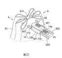
圖22顯示本發明之抽繩鎖的一第三較佳實施例,其包括一鎖殻1b、設於鎖殻1b上的一止動機構2b及連接止動機構2b的一鎖機構3b。鎖殻1b同樣能讓抽繩92的兩端穿過,使得抽繩92被鎖殻1b區分成位於鎖殻1b內的兩穿入段921、位於鎖殻1b外面且形成一封閉迴圈的一迴圈段922、及已穿過鎖殻1b的兩穿出段923。在此實施例中,如圖23所示,鎖殻1a包括一主殻11b及樞接於主殻11b上的兩擺臂12b ,兩擺臂12b可相對於主殻11b擺動。圖24顯示兩擺臂12b位於一展開位置,圖25顯示兩擺臂12b位於一收合位置。如圖23所示,每一擺臂12b各具有相通的一貫穿通道14b 及一側孔122b,抽繩92的兩端分別穿過兩貫穿通道14b。Figure 22 shows a third preferred embodiment of the drawstring lock of the present invention, which includes a
如圖23及24所示,止動機構2b包括兩止動塊21b及一插梢部22b。兩止動塊21b固設於主殻11b的兩相對側邊,且分別面對兩擺臂12b的兩側孔122b。插梢部22b連接鎖機構3b,且能緃向移動。插梢部22b還具有兩卡梢221b,兩卡梢221b可分別插入或脫離兩擺臂12b上的兩卡孔121b。As shown in Figures 23 and 24, the
鎖機構3b仍可選用第一較佳實施例中的號碼鎖心31。號碼鎖心31的移動桿311的一端固接插梢部22b。因此,當號碼鎖心31被撥出一正確密碼時,插梢部22b就可作緃向移動,此時可推或拉插梢部22b的一手柄220b ,使得插梢部22b沿一緃向而向前或向後移動。反之,當號碼鎖心31被撥出一不正確密碼時,插梢部22b就無法移動,此時是無法推動或拉動手柄220b的,換言之,止動機構2b此時是被鎖機構3b鎖住的。The
如圖24所示,當插梢部22b位於一原始位置時,兩擺臂12b呈展開狀態,使得抽繩92的兩穿入段921均未被兩止動塊21b均未壓制,故鎖殻1b此時能相對於兩穿入段921移動,亦即鎖殻1b可沿著抽繩92前、後移動。當號碼鎖心31被撥出一正確密碼而允許插梢部22b移動時,只要先將兩擺臂12b收合,就能推動位於鎖殻1b外面的手柄220b,以使插梢部22b從該原始位置推移到如圖25所示的一止動位置,此時,插梢部22b的兩卡梢221b分別插入兩擺臂12b上的兩卡孔121b,使得兩擺臂12b無法再展開。其中,於兩擺臂12b閉合時,兩止動塊21b分別壓制住兩擺臂12b中的兩穿入段921,使得鎖殻1b無法相對於兩穿入段921移動,亦即鎖殻1b無法沿著抽繩92前、後移動。接著,只要號碼鎖心31被撥出不正確密碼,插梢部22b就無法被往外拉動,這意味著兩穿入段921被兩止動塊21b壓制而無法相對於鎖殻1a移動之止動狀態將被維持住,直到號碼鎖心31被撥出正確密碼。一旦號碼鎖心31被撥出正確密碼,就可將手柄220b往外拉動,使得插梢部22b返回圖24所示的原位始置,此時,展開兩擺臂12b,以使兩止動塊21b不再壓制兩穿入段921,鎖殻1b就恢復可相對於兩穿入段921移動之原始狀態。As shown in Figure 24, when the
上述鎖機構3、3a 、3b均可用一鑰匙鎖心來取代上述的號碼鎖心31 。較佳地,上述鎖機構3、3a 、3b也可採用一雙鎖心機構,該雙鎖心機構包括能分別獨立鎖住或釋放上述止動機構的兩鎖心,或是包括能協同鎖住或釋放上述止動機構的兩鎖心,該兩鎖心可均為號碼鎖心或鑰匙鎖心,也可以其中一鎖心為一號碼鎖心,另一鎖心為一鑰匙鎖心。The above-mentioned
從上述說明可知,本發明之抽繩鎖的鎖殻1、1a或1b都能讓抽繩92的兩端穿過,並能沿著抽繩92前、後移動位置,藉以調整抽繩92的迴圈段922所形成的封閉迴圈的大小,且鎖殻1、1a或1b一旦到達想要的位置,便可操作止動機構2、2a或2b進入一止動狀態,以使抽繩92的穿入段921無法相對於鎖殻1、1a或1b移動,然後再將鎖機構3、3a或3b上鎖,藉以將止動機構2、2a或2b鎖定在該止動狀態下,以維持抽繩92的目前收束狀態(或是說維持迴圈段922目前所形成的封閉迴圈的大小),此時,除了該抽繩鎖的合法使用者之外,其它人就無再移動鎖殻1、1a或1b的位置,確保抽繩92的目前收束狀態不會被非法使用者改變或解除,解決習知抽繩的收束狀態易被改變或解除的問題。It can be seen from the above description that the
另外,上述抽繩92為一般塑膠或布質的材質,但也可以改用圖26及27中的一抽繩94來取代,抽繩94包括一金屬索941(例如一鋼索)及包覆金屬索941的一包覆層942,包覆層942可由塑膠或布質材料製成。較佳地,包覆層942還包括包圍金屬索941的一內層942a及包圍內層942a的一外層942b。In addition, the above-mentioned
1:鎖殻
11:底蓋
12:本體
13:開口
14:第一貫穿孔
15:第二貫穿孔
16:環形擋緣
17:限位塊
18、19:鎖槽
2:止動機構
21:扭轉塊
211、212:卡塊
213:通道
22:鈕
221、222:缺槽
223:孔
224、225:弧形凸緣
3:鎖機構
31:號碼鎖心
310:號碼輪
311:移動桿
312:彈簧
32:按鍵
33:鎖塊
1a:鎖殻
14a:貫穿通道
15a:溝槽
2a:止動機構
21a:止動塊
22a:推部
220a:手柄
222a:L型擋桿
3a:鎖機構
1b:鎖殻
11b:主殻
12b:擺臂
121b:卡孔
122b:側孔
14b:貫穿通道
2b:止動機構
21b:止動塊
22b:插梢部
220b:手柄
221b:卡梢
3b:鎖機構
9:束口包
910:袋口
91:袋體
92:抽繩
921:穿入段
922:迴圈段
923:穿出段
93:收束件
94:抽繩
941:金屬索
942:包覆層
942a:內層
942b:外層1: lock shell
11: bottom cover
12: body
13: opening
14: The first through hole
15: The second through hole
16: Ring flange
17:
圖1顯示本發明一第一較佳實施例使用於一束口包9的情形。
圖2及3顯示本發明該第一較佳實施例不同角度的立體分解圖。
圖4及5顯示本發明該第一較佳實施例不同角度的止動機構的立體圖。
圖6至8顯示本發明該第一較佳實施例的扭轉塊21位於一原始位置時的不同位置斷面圖。
圖9顯示本發明該第一較佳實施例的按鍵32被按下後的斷面圖
圖10至12顯示本發明該第一較佳實施例的鈕22位於一止動位置時的不同位置斷面圖。
圖13及14顯示該第一較佳實施例的鈕22被一限位塊17限位在該原始位置及該止動位置時的斷面圖。
圖15顯示本發明一第二較佳實施例使用於束口包9的情形。
圖16及17顯示本發明該第二較佳實施例不同角度的立體分解圖。
圖18及19顯示本發明該第二較佳實施例在一原始狀態及一止動狀態下的部分斷面圖。
圖20顯示本發明該第二較佳實施例的立體圖。
圖21顯示本發明該第二較佳實施例收納一抽繩92的一穿出段923時的平面圖。
圖22顯示本發明一第三較佳實施例使用於束口包9的情形。
圖23顯示本發明該第三較佳實施例的立體分解圖。
圖24及25顯示本發明該第三較佳實施例的在一原始狀態及一止動狀態下的部分斷面圖。
圖26顯示可穿過本發明之一抽繩93的部分立體斷面圖。
圖27顯示本發明之該抽繩93的部分斷面圖。
圖28及29顯示使用一收束件93的一束口包9在其袋口910展開及收攏時的部份立體圖。
FIG. 1 shows a first preferred embodiment of the present invention used in a
1:鎖殼 1: lock shell
2:止動機構 2: stop mechanism
3:鎖機構 3: lock mechanism
9:束口包 9: Beam mouth bag
910:袋口 910: bag mouth
91:袋體 91: bag body
92:抽繩 92: drawstring
921:穿入段 921: piercing section
922:迴圈段 922: loop section
923:穿出段 923: piercing
Claims (10)
Priority Applications (2)
| Application Number | Priority Date | Filing Date | Title |
|---|---|---|---|
| TW108138744A TWI722621B (en) | 2019-10-25 | 2019-10-25 | Drawstring lock |
| US17/079,092 US11339851B2 (en) | 2019-10-25 | 2020-10-23 | Drawstring lock |
Applications Claiming Priority (1)
| Application Number | Priority Date | Filing Date | Title |
|---|---|---|---|
| TW108138744A TWI722621B (en) | 2019-10-25 | 2019-10-25 | Drawstring lock |
Publications (2)
| Publication Number | Publication Date |
|---|---|
| TWI722621B true TWI722621B (en) | 2021-03-21 |
| TW202116213A TW202116213A (en) | 2021-05-01 |
Family
ID=75586658
Family Applications (1)
| Application Number | Title | Priority Date | Filing Date |
|---|---|---|---|
| TW108138744A TWI722621B (en) | 2019-10-25 | 2019-10-25 | Drawstring lock |
Country Status (2)
| Country | Link |
|---|---|
| US (1) | US11339851B2 (en) |
| TW (1) | TWI722621B (en) |
Families Citing this family (2)
| Publication number | Priority date | Publication date | Assignee | Title |
|---|---|---|---|---|
| US11326856B2 (en) * | 2019-05-20 | 2022-05-10 | Nelson R. De La Nuez | Gun safety storage system |
| CN113914723B (en) * | 2021-09-20 | 2022-09-16 | 陆境燃 | Safety tension lock |
Citations (3)
| Publication number | Priority date | Publication date | Assignee | Title |
|---|---|---|---|---|
| US4022486A (en) * | 1974-09-16 | 1977-05-10 | Plaiss Charles E | Lock |
| TWM266341U (en) * | 2004-10-07 | 2005-06-01 | Sinox Co Ltd | Cable lock |
| US20160298365A1 (en) * | 2015-04-07 | 2016-10-13 | Isaac Christensen | Cassette restraints |
Family Cites Families (9)
| Publication number | Priority date | Publication date | Assignee | Title |
|---|---|---|---|---|
| US1660040A (en) * | 1927-04-21 | 1928-02-21 | Lehtonen Matti | Cord and rope holder |
| US2292746A (en) * | 1939-07-27 | 1942-08-11 | Cleo E Boyd | Cable clamp |
| US2226393A (en) * | 1939-12-11 | 1940-12-24 | Baird Jr | Wire clamp |
| US4594752A (en) * | 1984-10-12 | 1986-06-17 | Garner Sr Ronald S | Cable or rope connection including clamp device |
| US4592116A (en) * | 1984-12-28 | 1986-06-03 | Christensen Harold B | Rope securing device |
| US4881302A (en) * | 1988-07-07 | 1989-11-21 | Lee So Sun K | Cord or rod clamp |
| US5572770A (en) * | 1995-08-18 | 1996-11-12 | Boden; Robert O. | Self locking cord lock |
| US5896623A (en) * | 1997-07-21 | 1999-04-27 | Martin; Mark | Reusable cable binder |
| FR2798176B1 (en) * | 1999-09-08 | 2001-10-12 | Salomon Sa | LACET FASTENER |
-
2019
- 2019-10-25 TW TW108138744A patent/TWI722621B/en not_active IP Right Cessation
-
2020
- 2020-10-23 US US17/079,092 patent/US11339851B2/en active Active
Patent Citations (3)
| Publication number | Priority date | Publication date | Assignee | Title |
|---|---|---|---|---|
| US4022486A (en) * | 1974-09-16 | 1977-05-10 | Plaiss Charles E | Lock |
| TWM266341U (en) * | 2004-10-07 | 2005-06-01 | Sinox Co Ltd | Cable lock |
| US20160298365A1 (en) * | 2015-04-07 | 2016-10-13 | Isaac Christensen | Cassette restraints |
Also Published As
| Publication number | Publication date |
|---|---|
| US20210123501A1 (en) | 2021-04-29 |
| US11339851B2 (en) | 2022-05-24 |
| TW202116213A (en) | 2021-05-01 |
Similar Documents
| Publication | Publication Date | Title |
|---|---|---|
| TWI722621B (en) | Drawstring lock | |
| KR101216733B1 (en) | Grip type handle for locking apparatus | |
| US6062051A (en) | Dial lock slide for a slide fastener | |
| CN107404986A (en) | Closing device component for baggage item | |
| RU2314398C2 (en) | Security lock | |
| TWM345107U (en) | Dual brake lock | |
| US3408839A (en) | Universal combination luggage lock | |
| CN113423906B (en) | Retractable cable lock with improved reset mechanism | |
| JP2020171659A (en) | Easy-to-use makeup pouch | |
| TWM493576U (en) | Door lock | |
| KR101663893B1 (en) | Door Lock for internal type | |
| TWI608154B (en) | Keyhole shielding device | |
| KR101527693B1 (en) | Dial type lock device | |
| CN204782320U (en) | Side lock and combination lock for combination lock | |
| TW201925589A (en) | Mobile device lock with simple locking effect allowing a user to lock a mobile device without using a key | |
| TW200928072A (en) | Lock with key mechanism | |
| US2669857A (en) | Locking device for bags, trunks, and the like | |
| KR200367910Y1 (en) | Hook | |
| CN100475077C (en) | Pivotal handle for towable baggage | |
| KR101195925B1 (en) | A door lock device | |
| JP7085916B2 (en) | Box confinement prevention device | |
| CN218894514U (en) | Automatic scramble lock | |
| CN221749767U (en) | A pull tab capable of crossing the lock hole on a zipper head | |
| US1944722A (en) | Novelty lock box | |
| US949548A (en) | Door-lock. |
Legal Events
| Date | Code | Title | Description |
|---|---|---|---|
| MM4A | Annulment or lapse of patent due to non-payment of fees |