在下述的實施方式的說明中,真實世界座標系(World Coordinate System)和攝影機座標系皆是三維座標系。三維座標系是由原點以及互相垂直的軸、軸、軸所構成。三維座標系根據、、三軸所依循的向量的相對關係,可分為左手座標系與右手座標系。其中,左手座標系是以左手大拇指朝向軸正向,四指向手掌彎曲的方向是從軸正向轉為軸正向。右手座標系為以右手大拇指朝向軸正向,四指向手掌彎曲的方向是從軸正向轉為軸正向。真實世界座標系和攝影機座標系可以同屬於左手座標系或同屬於右手座標系。本揭露不限於此。In the description of the following embodiments, both the real world coordinate system (World Coordinate System) and the camera coordinate system are three-dimensional coordinate systems. The three-dimensional coordinate system is from the origin and perpendicular to each other axis, axis, Constituted by the shaft. The three-dimensional coordinate system is based on , , The relative relationship of the vectors followed by the three axes can be divided into a left-handed coordinate system and a right-handed coordinate system. Among them, the left hand coordinate system is oriented with the thumb of the left hand The axis is positive, the four-pointing palm bending direction is from Axis positive turn into The axis is positive. The right-hand coordinate system is oriented with the thumb of the right hand The axis is positive, the four-pointing palm bending direction is from Axis positive turn into The axis is positive. The real-world coordinate system and the camera coordinate system can belong to the same left-hand coordinate system or the same right-hand coordinate system. This disclosure is not limited to this.
真實世界座標系是標示物體在真實世界的空間位置所採用的座標系。此座標系的軸正向為經由地心穿過地面向上的方向,為地平面,平面垂直於軸。舉例來說,真實世界座標系可以採用世界大地測量系統(World Geodetic System,WGS)來實現,又或者是,在本揭露的其他實施例中,原點位置、軸方向和軸方向皆由觀測者自行定義,端看觀測者期望以何種參考體系來描述物體位置。本揭露不限於此。The real-world coordinate system is the coordinate system used to indicate the spatial position of an object in the real world. Of this coordinate system The positive axis is the upward direction through the ground through the center of the earth, Is the ground plane, Plane perpendicular to axis. For example, the real-world coordinate system can be implemented by using the World Geodetic System (WGS), or, in other embodiments of the present disclosure, the origin position, Axis direction and The direction of the axis is defined by the observer. It depends on what kind of reference system the observer expects to describe the position of the object. This disclosure is not limited to this.
攝影機座標系是以攝影機鏡頭中央點為原點所形成的三維座標系。攝影機座標系會以相應於左手或右手座標系的方式定義三維座標系的三軸方向。The camera coordinate system is a three-dimensional coordinate system formed by the center point of the camera lens as the origin. The camera coordinate system defines the three-axis direction of the three-dimensional coordinate system in a manner corresponding to the left-handed or right-handed coordinate system.
影像座標系是攝影機拍攝的影像所屬的座標系統,也就是說,影像座標系實際上是二維座標系。影像座標系由影像原點、軸、以及軸所構成。在本揭露的一實施例中,影像座標系的原點位於影像平面正中央,軸方向為水平由左向右,軸方向為垂直由下向上,然本揭露不限於此。影像座標系會相應於攝影機座標系,具體而言,當物體在影像座標系中的影像座標與在真實世界座標系的真實座標間切換時,是通過中介的攝影機座標系進行轉換。The image coordinate system is the coordinate system to which the image shot by the camera belongs, that is to say, the image coordinate system is actually a two-dimensional coordinate system. The image coordinates are from the image origin, Shaft, and Constituted by the shaft. In an embodiment of the present disclosure, the origin of the image coordinate system is located in the center of the image plane, The axis direction is horizontal from left to right, The axis direction is vertical from bottom to top, but the disclosure is not limited to this. The image coordinate system will correspond to the camera coordinate system. Specifically, when the object is switched between the image coordinate in the image coordinate system and the real coordinate in the real world coordinate system, the conversion is performed through the intermediary camera coordinate system.
圖1繪示本揭露一實施例影像定位系統的系統示意圖。請參照圖1,影像定位系統100具有攝影機110、儲存單元120以及處理單元130。FIG. 1 shows a system schematic diagram of an image positioning system according to an embodiment of the disclosure. Please refer to FIG. 1, the image positioning system 100 has a camera 110, a storage unit 120 and a processing unit 130.
攝影機110用以獲取影像,並且,攝影機110會對應外部參數(Extrinsic Parameters)以及內部參數(Intrinsic Parameters)。外部參數相應於真實世界座標與攝影機座標(Camera Coordinates)之間的轉換關係,例如但不限於,旋轉(Rotation)資訊以及平移(Translation)資訊。內部參數則是相應於攝影機座標以及影像平面座標的轉換關係,例如但不限於,攝影機焦距、影像畫面中心點資訊以及攝影機透鏡變形(Lens Distortion)等參數。攝影機110可以採用任何型號及任何品牌發行的攝影機所實現,本揭露不限於此。The camera 110 is used to obtain images, and the camera 110 corresponds to external parameters (Extrinsic Parameters) and internal parameters (Intrinsic Parameters). The external parameters correspond to the conversion relationship between real world coordinates and camera coordinates (Camera Coordinates), such as, but not limited to, rotation (Rotation) information and translation (Translation) information. The internal parameters correspond to the conversion relationship between the camera coordinates and the image plane coordinates, such as but not limited to parameters such as the camera focal length, the image center point information, and the camera lens distortion (Lens Distortion). The camera 110 can be implemented by a camera issued by any model and brand, and the disclosure is not limited to this.
儲存單元120用以儲存影像定位系統100執行時所需的各類程式碼與資料。特別是,儲存單元120儲存座標轉換參數。儲存單元120例如但不限於,以任何型態的固定或可移動隨機存取記憶體(Random Access Memory,RAM)、唯讀記憶體(Read-Only Memory,ROM)、快閃記憶體(flash memory)、硬碟(Hard Disk Drive,HDD)、固態硬碟(Solid State Drive,SSD)或類似元件或上述元件的組合所實現,且本揭露不限於此。The storage unit 120 is used to store various kinds of program codes and data required by the image positioning system 100 during execution. In particular, the storage unit 120 stores the coordinate conversion parameters. The storage unit 120 is, for example, but not limited to, any type of fixed or removable random access memory (Random Access Memory, RAM), read-only memory (Read-Only Memory, ROM), and flash memory (flash memory). ), a hard disk (Hard Disk Drive, HDD), a solid state drive (Solid State Drive, SSD) or similar components or a combination of the above components, and the present disclosure is not limited thereto.
處理單元130連接攝影機110以及儲存單元120,用以接收來自攝影機110的影像、存取儲存單元120的程式碼與資料、對數據運算與處理等,以完成影像定位系統100所需的各類運算。處理單元130例如為,中央處理單元(Central Processing Unit,CPU),或是其他可程式化之一般用途或特殊用途的微處理器(Microprocessor)、數位信號處理器(Digital Signal Processor,DSP)、可程式化控制器、特殊應用積體電路(Application Specific Integrated Circuit,ASIC)或其他類似元件或上述元件的組合,本揭露不限於此。The processing unit 130 is connected to the camera 110 and the storage unit 120 to receive the image from the camera 110, access the code and data of the storage unit 120, calculate and process the data, etc., to complete various operations required by the image positioning system 100 . The processing unit 130 is, for example, a central processing unit (Central Processing Unit, CPU), or other programmable general-purpose or special-purpose microprocessors (Microprocessors), digital signal processors (Digital Signal Processors, DSPs), and Programmable controller, Application Specific Integrated Circuit (ASIC) or other similar components or combinations of the above components are not limited to this disclosure.
在本揭露的一實施例中,影像定位系統100的攝影機110會以外接的方式連接於處理單元130,或者是,儲存單元120與處理單元130會被配置在攝影機110當中,並連接於攝影機110的各類電性元件,本揭露不限於此。In an embodiment of the present disclosure, the camera 110 of the image positioning system 100 is connected to the processing unit 130 in an external manner, or the storage unit 120 and the processing unit 130 are configured in the camera 110 and connected to the camera 110 The present disclosure is not limited to all kinds of electrical components.
圖2繪示本揭露一實施例影像定位方法的流程示意圖。圖2的影像定位方法至少適用於圖1的影像定位系統100,然本揭露不限於此。請參照圖1與圖2,以下將通過圖1與圖2說明影像定位系統100運行影像定位方法的過程。FIG. 2 is a schematic flowchart of an image positioning method according to an embodiment of the disclosure. The image positioning method of FIG. 2 is at least applicable to the image positioning system 100 of FIG. 1, but the present disclosure is not limited to this. Please refer to FIG. 1 and FIG. 2. The process of the image positioning system 100 running the image positioning method will be described below through FIG. 1 and FIG. 2.
在步驟S210,由處理單元130獲取二個參考點的真實座標以及相應二個參考點的二個投影點的影像座標。並且,在步驟S220,由處理單元130僅依據二個參考點的真實座標、二個投影點的影像座標和攝影機110的真實座標計算相應於攝影機的任一影像座標和任一真實座標之間轉換的多個座標轉換參數。In step S210, the processing unit 130 obtains the real coordinates of the two reference points and the image coordinates of the two projection points corresponding to the two reference points. In addition, in step S220, the processing unit 130 only calculates the conversion between any image coordinate of the camera and any real coordinate based on the real coordinates of the two reference points, the image coordinates of the two projection points, and the real coordinates of the camera 110. The multiple coordinate conversion parameters.
具體來說,二個參考點是任意二個存在於真實世界的點。處理單元130會接收使用者所輸入二個參考點的真實座標。或者是,在本揭露另一實施例中,二個參考點上具有配置位置偵測單元(例如但不限於,支援全球定位系統Global Positioning System,GPS的晶片)的電子裝置。處理單元130會通訊連接於兩個參考點上的電子裝置,以自動地獲取二個參考點的真實座標,本揭露不限於此。相似地,處理單元130也會通過使用者的輸入或者是配置於攝影機110上的位置偵測單元獲取攝影機110的真實座標。本揭露並不以上述實施例為限。具體來說,攝影機110的真實座標對應於攝影機110鏡頭的真實座標,特別是表示為攝影機110鏡頭中心點的真實座標。Specifically, the two reference points are any two points that exist in the real world. The processing unit 130 receives the real coordinates of the two reference points input by the user. Or, in another embodiment of the present disclosure, an electronic device equipped with a position detection unit (for example, but not limited to, a chip supporting the Global Positioning System, GPS) is provided on the two reference points. The processing unit 130 is communicatively connected to the electronic devices on the two reference points to automatically obtain the real coordinates of the two reference points, and the disclosure is not limited to this. Similarly, the processing unit 130 also obtains the real coordinates of the camera 110 through the user's input or the position detection unit disposed on the camera 110. The present disclosure is not limited to the above-mentioned embodiments. Specifically, the real coordinates of the camera 110 correspond to the real coordinates of the lens of the camera 110, especially expressed as the real coordinates of the center point of the lens of the camera 110.
此外,處理單元130會接收攝影機110所擷取的影像,此影像中亦具有相應二個投影點。處理單元130會依據二個參考點分析影像,進而獲取相應二個投影點在影像座標系上的影像座標。又或者是,處理單元130也可以通過使用者自行輸入的方式獲取二個投影點在影像座標系上的影像座標。藉此,處理單元130可以通過攝影機的真實座標、二個參考點的真實座標及其相應的投影點在影像座標系上的影像座標,進而獲取相應於攝影機的任一影像座標和任一真實座標之間轉換的多個座標轉換參數,包括相應於真實世界座標和攝影機座標之間轉換的外部參數、以及相應於攝影機座標和影像座標之間轉換的內部參數。處理單元130會將座標轉換參數記錄在儲存單元120中。通過攝影機的真實座標、二個參考點的真實座標及其相應的投影點在影像座標系上的影像座標,進而獲取相應於攝影機的任一影像座標和任一真實座標之間轉換的多個座標轉換參數的細節將於後方再進行說明。In addition, the processing unit 130 receives the image captured by the camera 110, and the image also has two corresponding projection points. The processing unit 130 analyzes the image according to the two reference points, and then obtains the image coordinates of the corresponding two projection points on the image coordinate system. Alternatively, the processing unit 130 may also obtain the image coordinates of the two projection points on the image coordinate system through the user's own input. Thereby, the processing unit 130 can obtain any image coordinate and any real coordinate corresponding to the camera through the real coordinates of the camera, the real coordinates of the two reference points, and the corresponding projection points on the image coordinate system. The multiple coordinate conversion parameters for conversion include external parameters corresponding to the conversion between real world coordinates and camera coordinates, and internal parameters corresponding to conversion between camera coordinates and image coordinates. The processing unit 130 records the coordinate conversion parameters in the storage unit 120. Through the real coordinates of the camera, the real coordinates of the two reference points and the image coordinates of the corresponding projection points on the image coordinate system, multiple coordinates corresponding to the conversion between any image coordinate and any real coordinate of the camera are obtained The details of the conversion parameters will be explained later.
在步驟S230,由攝影機110獲取影像(第二影像)。在本實施例中,影像中具有相應一物體的物體影像,此物體影像會對應影像座標系統中的影像座標。在步驟S240,由處理單元130依據座標轉換參數,定位物體的真實座標。具體來說,由於儲存單元120儲存座標轉換參數,因此,在處理單元130獲取攝影機110拍攝的影像時,能夠直接依據座標轉換參數而將物體的影像座標轉換為此物體在真實世界座標系中的真實座標。In step S230, an image (second image) is acquired by the camera 110. In this embodiment, the image has an object image corresponding to an object, and the object image corresponds to the image coordinates in the image coordinate system. In step S240, the processing unit 130 locates the real coordinates of the object according to the coordinate conversion parameters. Specifically, since the storage unit 120 stores the coordinate conversion parameters, when the processing unit 130 obtains the image taken by the camera 110, it can directly convert the image coordinates of the object into the real-world coordinate system according to the coordinate conversion parameters. Real coordinates.
以下將採用第一實施例說明通過攝影機的真實座標、二個參考點的真實座標及其相應的投影點在影像座標系上的影像座標,進而獲取相應於攝影機的任一影像座標和任一真實座標之間轉換的多個座標轉換參數的細節。In the following, the first embodiment will be used to illustrate that the real coordinates of the camera, the real coordinates of the two reference points and the corresponding projection points on the image coordinate system are used to obtain any image coordinates and any real coordinates corresponding to the camera. Details of multiple coordinate conversion parameters for conversion between coordinates.
需先說明的是,在此實施例中,真實世界座標系和攝影機座標系為左手座標系。也就是說,左手拇指為軸正向,四指彎曲的方向是從軸正向轉為軸正向。並且,以下實施例中,處理單元130所決定的攝影機座標系皆是以攝影機鏡頭中心點作為攝影機座標系的原點(0,0,0),攝影機鏡頭直視的方向作為攝影機座標系的軸正向,並依據相應於左手座標系的向量,進而決定攝影機110直視方向的水平右方為攝影機座標系的軸正向,攝影機110直視方向的垂直上方為攝影機座標系的軸正向。並且,當攝影機110繞軸旋轉角不為零時,攝影機所拍攝的真實世界的水平和垂直方向反映在影像畫面,與影像座標系的軸和軸方向不一致。It should be noted that, in this embodiment, the real world coordinate system and the camera coordinate system are the left-hand coordinate system. In other words, the left thumb is The axis is positive, the direction of bending of the four fingers is from Axis positive turn into The axis is positive. In addition, in the following embodiments, the camera coordinate system determined by the processing unit 130 is based on the center point of the camera lens as the origin (0,0,0) of the camera coordinate system, and the direction in which the camera lens looks directly as the camera coordinate system The axis is positive, and according to the vector corresponding to the left-hand coordinate system, the horizontal right of the camera 110’s direct view direction is determined as the camera coordinate system Axis positive, the vertical above the camera 110’s direct viewing direction is the camera coordinate system The axis is positive. And, when the camera 110 goes around When the axis rotation angle is not zero, the horizontal and vertical directions of the real world shot by the camera are reflected in the image screen, and the coordinate system of the image is Shaft and The axis directions are inconsistent.
除此之外,在獲取相應於攝影機的任一影像座標和任一真實座標之間轉換的多個座標轉換參數時,會運用第一中途座標系、第二中途座標系以及第三中途座標系獲取座標轉換參數。具體來說,由於攝影機座標系以及真實世界座標系都是採用三維空間的直角座標系,因此,彼此之間會存在數值上相依的關係(例如,角度相依、距離相依等)。第一中途座標系、第二中途座標系以及第三中途座標系即為由真實世界座標系轉換成攝影機座標系的中途所形成的座標系。並且,下述對應於每一座標系,第一座標軸為該座標系的軸、第二座標軸為該座標系的軸、第三座標軸為該座標系的軸。例如,對應於真實世界座標系,(真實)第一座標軸、(真實)第二座標軸、(真實)第三座標軸分別為真實世界座標系的軸、軸和軸;對應於第一中途座標系,(中途)第一座標軸、(中途)第二座標軸、(中途)第三座標軸分別為第一中途座標系的軸、軸和軸;對應於第二中途座標系,(中途)第一座標軸、(中途)第二座標軸、(中途)第三座標軸分別為第二中途座標系的軸、軸和軸;對應於第三中途座標系,(中途)第一座標軸、(中途)第二座標軸、(中途)第三座標軸分別為第三中途座標系的軸、軸和軸;對應於攝影機座標系,(攝影機)第一座標軸、(攝影機)第二座標軸、(攝影機)第三座標軸分別為攝影機座標系的軸、軸和軸。然本揭露不限於此。In addition, when obtaining multiple coordinate conversion parameters corresponding to the conversion between any image coordinate of the camera and any real coordinate, the first midway coordinate system, the second midway coordinate system, and the third midway coordinate system are used Get the coordinate conversion parameters. Specifically, since both the camera coordinate system and the real-world coordinate system use a three-dimensional orthogonal coordinate system, there will be a numerically dependent relationship between each other (for example, angle dependence, distance dependence, etc.). The first midway coordinate system, the second midway coordinate system, and the third midway coordinate system are the coordinate systems formed during the conversion from the real world coordinate system to the camera coordinate system. And, the following corresponds to each coordinate system, the first coordinate axis is the coordinate system Axis, the second coordinate axis is the coordinate system Axis, the third coordinate axis is the coordinate system axis. For example, corresponding to the real-world coordinate system, the (real) first coordinate axis, (real) second coordinate axis, and (real) third coordinate axis are respectively the real-world coordinate system axis, Shaft and Axis; corresponding to the first midway coordinate system, the (midway) first coordinate axis, (midway) second coordinate axis, (midway) third coordinate axis are respectively the first midway coordinate system axis, Shaft and Axis; corresponding to the second midway coordinate system, the (midway) first coordinate axis, (midway) second coordinate axis, (midway) third coordinate axis are respectively the second midway coordinate system axis, Shaft and Axis; corresponding to the third midway coordinate system, the (midway) first coordinate axis, (midway) second coordinate axis, (midway) third coordinate axis are respectively the third midway coordinate system axis, Shaft and Axis; corresponding to the camera coordinate system, the (camera) first coordinate axis, (camera) second coordinate axis, (camera) third coordinate axis are respectively the camera coordinate system axis, Shaft and axis. However, this disclosure is not limited to this.
圖3及圖4繪示本揭露一實施例的真實世界座標系與攝影機座標系的轉換示意圖。請參照圖3,具體來說,圖3的(1)對應於真實世界座標系。此時,攝影機座標系的軸、軸及軸分別與真實世界座標系的軸、軸及軸重疊,攝影機110鏡頭中心的真實座標為(0,0,0)。3 and 4 are schematic diagrams showing the conversion between the real world coordinate system and the camera coordinate system according to an embodiment of the disclosure. Please refer to FIG. 3. Specifically, (1) of FIG. 3 corresponds to the real world coordinate system. At this time, the camera coordinate system axis, Shaft and Axis and real-world coordinate system axis, Shaft and The axes overlap, and the real coordinates of the lens center of the camera 110 are (0,0,0).
圖3的(2)對應第一中途座標系,相較於真實世界座標系,第一中途座標系整體會被平移,而使攝影機110原點的真實座標由(0,0,0)被平移至(,,)。此時,軸、軸、軸的方向維持不變,但跟隨著原點被平移,形成第一中途座標系的軸、軸與軸。在本實施例中,、、是任意實數,然不限於此。Figure 3 (2) corresponds to the first midway coordinate system. Compared with the real world coordinate system, the first midway coordinate system will be translated as a whole, and the real coordinates of the origin of the camera 110 will be translated from (0,0,0) to( , , ). at this time, axis, axis, The direction of the axis remains unchanged, but it is translated following the origin to form the first midway coordinate system axis, Axis and axis. In this embodiment, , , It is any real number, but it is not limited to this.
圖3的(3)對應第二中途座標系,相較於第一中途座標系,第二中途座標系會繞著軸旋轉的角度。同時,請參考圖4的(1)所繪示攝影機的俯視圖。相較於第一中途座標系,第二中途座標系的原點及中途第三座標軸維持不變,因此,軸等同於軸,但軸與軸的方向皆向同一方向旋轉了的角度,形成第二中途座標系的軸與軸。(3) of Figure 3 corresponds to the second midway coordinate system. Compared with the first midway coordinate system, the second midway coordinate system will go around Axis rotation Angle. At the same time, please refer to the top view of the camera shown in Figure 4 (1). Compared with the first midway coordinate system, the origin of the second midway coordinate system and the midway third coordinate axis remain unchanged. Therefore, The axis is equivalent to Shaft but Axis and The directions of the axes are all rotated in the same direction Angle, forming the second midway coordinate system Axis and axis.
圖3的(4)對應第三中途座標系,相較於第二中途座標系,第三中途座標系會繞著軸旋轉的角度。同時,請參考圖4的(2)所繪示攝影機的側視圖。相較於第二中途座標系,第三中途座標系的原點及中途第二座標軸維持不變,因此,軸等同於軸,但軸與軸的方向皆向同一方向旋轉了的角度,形成第三中途座標系的軸及軸。(4) of Figure 3 corresponds to the third midway coordinate system. Compared with the second midway coordinate system, the third midway coordinate system will go around Axis rotation Angle. At the same time, please refer to the side view of the camera shown in Figure 4 (2). Compared with the second midway coordinate system, the origin of the third midway coordinate system and the midway second coordinate axis remain unchanged. Therefore, The axis is equivalent to Shaft but Axis and The directions of the axes are all rotated in the same direction Angle, forming the third midway coordinate system Shaft and axis.
圖3的(5)對應攝影機座標系,相較於第三中途座標系,攝影機座標系會繞著軸旋轉θx
的角度。同時,請參考圖4的(3)所繪示攝影機的前視圖。相較於第三中途座標系,攝影機座標系的原點及第一座標軸維持不變,因此,軸等同於軸,但軸與軸的方向皆向同一方向旋轉了的角度,形成攝影機座標系的軸及軸。經過平移以及、、軸的角度調整,攝影機的位置及方向皆由真實世界座標系轉換成為攝影機座標系。(5) of Figure 3 corresponds to the camera coordinate system. Compared to the third midway coordinate system, the camera coordinate system moves around The axis is rotated by the angle θ x. At the same time, please refer to the front view of the camera shown in Figure 4 (3). Compared with the third midway coordinate system, the origin of the camera coordinate system and the first coordinate axis remain unchanged. Therefore, The axis is equivalent to Shaft but Axis and The directions of the axes are all rotated in the same direction Angle, forming the camera coordinate system Shaft and axis. After panning and , , The angle adjustment of the axis, the position and direction of the camera are converted from the real world coordinate system to the camera coordinate system.
相反地,倘若欲從攝影機座標系轉換回真實世界座標系時,攝影機座標系會經過第三中途座標系、第二中途座標系以及第一中途座標系後,轉換回真實世界座標系。Conversely, if you want to convert from the camera coordinate system back to the real world coordinate system, the camera coordinate system will be converted back to the real world coordinate system after passing through the third midway coordinate system, the second midway coordinate system, and the first midway coordinate system.
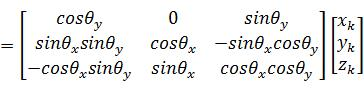
值得一提的是,倘若處理單元130已知物體在真實世界座標系的真實座標為(,,),處理單元130能夠依據真實世界座標系的真實座標轉換為物體在攝影機座標系的空間座標(,,)。處理單元130將真實世界座標系的真實座標轉換為攝影機座標系的空間座標可以被表示為方程式(1):(1)
其中,、以及分別對應於攝影機鏡頭在真實世界座標系的真實座標(,,)。矩陣、、分別是用以代表在第一座標軸、第二座標軸以及第三座標軸的旋轉,矩陣運算的順序相應於真實世界座標系轉換為攝影機座標系的過程。、、可以被表示為方程式(2):,,(2)It is worth mentioning that if the processing unit 130 knows that the real coordinates of the object in the real world coordinate system are ( , , ), the processing unit 130 can convert the real coordinates of the object in the camera coordinate system according to the real coordinates of the real world coordinate system ( , , ). The processing unit 130 converts the real coordinates of the real world coordinate system into the space coordinates of the camera coordinate system, which can be expressed as equation (1): (1) Among them, , as well as They correspond to the real coordinates of the camera lens in the real world coordinate system ( , , ). matrix , , They are used to represent the rotation on the first coordinate axis, the second coordinate axis, and the third coordinate axis. The sequence of matrix operations corresponds to the process of converting the real world coordinate system to the camera coordinate system. , , Can be expressed as equation (2): , , (2)
相反地,倘若物體在攝影機座標系的空間座標為(,,),處理單元130能夠依據攝影機座標系的空間座標(,,)進而獲取物體在真實世界座標系的真實座標(,,)。處理單元130獲取物體在真實世界座標系的真實座標的過程可以被表示為下述座標轉換方程式(3):(3)
其中,矩陣、、分別是用以代表在第一座標軸、第二座標軸以及第三座標軸的反向旋轉,矩陣運算的順序相應於攝影機座標系轉換為真實世界座標系的過程。、、可以被表示為方程式(4):,,(4)Conversely, if the spatial coordinates of the object in the camera coordinate system are ( , , ), the processing unit 130 can be based on the spatial coordinates of the camera coordinate system ( , , ) And then obtain the real coordinates of the object in the real world coordinate system ( , , ). The process of the processing unit 130 obtaining the real coordinates of the object in the real world coordinate system can be expressed as the following coordinate conversion equation (3): (3) Among them, the matrix , , They are used to represent the reverse rotation on the first coordinate axis, the second coordinate axis, and the third coordinate axis. The sequence of matrix operations corresponds to the process of converting the camera coordinate system to the real world coordinate system. , , It can be expressed as equation (4): , , (4)
然而,由於相較於真實世界座標系,攝影機座標系會因攝影機110設置的位置與角度等外部參數而有所不同。並且,對應於攝影機座標系的空間座標,物體呈現在影像座標系的影像座標也會與攝影機110的焦距等內部參數相關。因此,通過獲取座標轉換參數並儲存在儲存單元120中,可以加速物體在真實世界座標與影像座標的切換運算,更進一步地對影像中的物體進行定位。However, as compared with the real world coordinate system, the camera coordinate system may be different due to external parameters such as the position and angle set by the camera 110. In addition, corresponding to the spatial coordinates of the camera coordinate system, the image coordinates of the object presented in the image coordinate system are also related to internal parameters such as the focal length of the camera 110. Therefore, by acquiring the coordinate conversion parameters and storing them in the storage unit 120, the switching operation between the real world coordinates and the image coordinates of the object can be accelerated, and the object in the image can be further positioned.
圖5繪示本揭露一實施例影像定位方法的部分細部流程圖。圖6繪示相應圖5實施例二個參考點的幾何示意圖。圖7繪示相應圖5實施例獲取焦距參數的幾何示意圖。以下將由圖5至圖7說明通過攝影機的真實座標、二個參考點的真實座標及其相應的投影點在影像座標系的影像座標,進而獲取相應於攝影機的任一影像座標和任一真實座標之間轉換的多個座標轉換參數的流程。FIG. 5 shows a partial detailed flowchart of an image positioning method according to an embodiment of the disclosure. FIG. 6 is a geometrical schematic diagram of two reference points corresponding to the embodiment in FIG. 5. FIG. 7 is a geometrical schematic diagram of obtaining focal length parameters corresponding to the embodiment in FIG. 5. The following will illustrate the real coordinates of the camera, the real coordinates of the two reference points and the image coordinates of the corresponding projection points in the image coordinate system from Figures 5 to 7, and then obtain any image coordinates and any real coordinates corresponding to the camera The process of converting multiple coordinate conversion parameters between.
請參照圖5至圖7,在圖5步驟S510,由處理單元130獲取來自攝影機110的輸出影像(第一影像),並獲取相應輸出影像的解析度資訊,以依據解析度資訊獲取影像中心點的影像座標。Referring to FIGS. 5 to 7, in step S510 of FIG. 5, the processing unit 130 obtains the output image (first image) from the camera 110, and obtains the resolution information of the corresponding output image, so as to obtain the image center point according to the resolution information The image coordinates.
具體來說,解析度資訊相應於輸出影像的寬高解析度。因此,處理單元130獲取影像的寬高解析度後,會依據解析度資訊而將影像座標化,並對影像進行分析。藉此,處理單元130會進而推知二個投影點的影像座標。舉例來說,在解析度為19201080,且以左上角為原點、橫座標軸為由左向右、縱座標軸為由上至下的影像中,影像中心點的影像座標為(960,540)。倘若投影點的影像座標為(,),投影點的影像座標為(,),在本實施例中,處理單元130會進一步設定影像中心點的影像座標為原點(0,0)、橫座標軸為由左向右、縱座標軸為由下向上。也就是說,影像左上角的座標將由(0, 0)轉變為(-960, 540),投影點的影像座標為(,) =(,+540),投影點的影像座標為(,)=(,+540)。然本揭露不限於此。Specifically, the resolution information corresponds to the width and height resolution of the output image. Therefore, after the processing unit 130 obtains the width and height resolution of the image, it coordinates the image according to the resolution information and analyzes the image. In this way, the processing unit 130 further infers the image coordinates of the two projection points. For example, at a resolution of 1920 1080, and in the image with the upper left corner as the origin, the abscissa axis from left to right, and the ordinate axis from top to bottom, the image coordinates of the center point of the image are (960,540). If the projection point The image coordinates of is ( , ), the projection point The image coordinates of is ( , ). In this embodiment, the processing unit 130 further sets the image coordinates of the image center point as the origin (0, 0), the horizontal axis is from left to right, and the vertical axis is from bottom to top. In other words, the coordinates of the upper left corner of the image will change from (0, 0) to (-960, 540), and the projection point The image coordinates of is ( , ) = ( , +540), projection point The image coordinates of is ( , )=( , +540). However, this disclosure is not limited to this.
詳細來說,請同時參照圖5至圖6。在圖6中,二個參考點分別是在真實世界座標系中的第一參考點以及第二參考點。並且,攝影機110會拍攝並輸出影像。輸出影像相應於影像座標系,並具有相應二個參考點的第一投影點及第二投影點。攝影機鏡頭中心點被標示為,攝影機座標系的軸穿過攝影機鏡頭,並與地面形成中心交點。由攝影機鏡頭中心點至第一參考點的參考距離為,由攝影機鏡頭中心點至第二參考點的參考距離為,由第一參考點至第二參考點的參考距離為。攝影機鏡頭中心點與地面垂直交會形成垂直交點,由攝影機鏡頭中心點至垂直交點的高度為。In detail, please refer to Figures 5 to 6 at the same time. In Figure 6, the two reference points are the first reference point in the real-world coordinate system. And the second reference point . In addition, the camera 110 will shoot and output images. The output image corresponds to the image coordinate system and has a first projection point corresponding to two reference points And the second projection point . The center point of the camera lens is marked as , The camera coordinate system The axis passes through the camera lens , And form a central intersection with the ground . From the center point of the camera lens To the first reference point The reference distance is , From the center point of the camera lens To the second reference point The reference distance is , By the first reference point To the second reference point The reference distance is . Camera lens center point Vertical intersection with the ground to form a vertical intersection , From the center point of the camera lens To vertical intersection The height is .
除此之外,圖6存在垂直軸的投影面,也就是說,此投影面平行於攝影機110成像的平面,並且相應於攝影機110的輸出影像。由於在本實施例中,軸為攝影機鏡頭直視的方向,且攝影機座標系的軸會消失在影像座標系的中心點以形成二維的空間。因此,攝影機鏡頭中心點投影在影像座標系上的投影位置可視為影像中心點。攝影機鏡頭中心點和其投影點的距離即為攝影機鏡頭中心點對於此投影面的焦距。此外,投影面分別與攝影機鏡頭中心點及第一參考點、第二參考點所形成的直線以及相交,形成相應第一參考點以及第二參考點的第一投影點以及第二投影點。並且,請參照圖7,影像中心點和第一投影點的投影距離為,影像中心點和第二投影點的投影距離為,第一投影點和第二投影點的投影距離為。In addition, Figure 6 has vertical Projection surface of the axis , That is, this projection surface It is parallel to the imaging plane of the camera 110 and corresponds to the output image of the camera 110. Because in this embodiment, The axis is the direction of the camera lens, and the camera coordinate system The axis will disappear at the center point of the image coordinate system to form a two-dimensional space. Therefore, the center point of the camera lens The projection position projected on the image coordinate system can be regarded as the image center point . Camera lens center point And its projection point The distance is the center point of the camera lens For this projection surface Focal length . In addition, the projection surface Respectively and the camera lens center point And the first reference point , The second reference point Straight line formed as well as Intersect to form the corresponding first reference point And the second reference point The first projection point And the second projection point . And, please refer to Figure 7, the image center point And the first projection point The projection distance is , The image center point And the second projection point The projection distance is , The first projection point And the second projection point The projection distance is .
在步驟S520,由處理單元130依據攝影機鏡頭及二個參考點的真實座標決定攝影機鏡頭與二個參考點之間的參考距離。In step S520, the processing unit 130 determines the reference distance between the camera lens and the two reference points according to the real coordinates of the camera lens and the two reference points.
由於處理單元130已獲取二個參考點、以及攝影機鏡頭中心點的真實座標,因此,處理單元130會依據二個參考點、的真實座標計算攝影機鏡頭中心點與第一參考點的參考距離、攝影機鏡頭中心點與第二參考點的參考距離、以及第一參考點與第二參考點的參考距離。在本揭露的其他實施例中,處理單元130也可以直接接收來自使用者所輸入的參考距離、參考距離、以及參考距離,本揭露不限於此。需說明的是,參考距離、及可以採用距離單位(例如,公分、公厘)來表示,也可以採用影像像素(Pixel)為單位,本揭露不限於此。處理單元130會自動將所有參數、變數轉換成為同一個單位。舉例來說,在一個實施例中,1公分相當於37.795275591像素。處理單元130即能據此而使所有的參數、變數在公分與像素之間轉換。Since the processing unit 130 has acquired two reference points , And the center point of the camera lens Therefore, the processing unit 130 will base on the two reference points , Calculate the center point of the camera lens with the true coordinates With the first reference point Reference distance , Camera lens center point With the second reference point Reference distance , And the first reference point With the second reference point Reference distance . In other embodiments of the present disclosure, the processing unit 130 may also directly receive the reference distance input from the user. , Reference distance , And reference distance , This disclosure is not limited to this. It should be noted that the reference distance , and It can be expressed in distance units (for example, centimeters, millimeters), and can also be expressed in image pixels (Pixel), and the present disclosure is not limited to this. The processing unit 130 automatically converts all parameters and variables into the same unit. For example, in one embodiment, 1 cm is equivalent to 37.795275591 pixels. The processing unit 130 can convert all parameters and variables between centimeters and pixels accordingly.
在步驟S530,由處理單元130依據二個投影點、的影像座標決定影像中心點與二個投影點、之間的投影距離。由於處理單元130已獲取二個投影點、以及影像中心點的影像座標,在一實施例中,影像中心點的影像座標為原點(0, 0),處理單元130會依據二個投影點、的影像座標,進而決定影像中心點與第一投影點的投影距離、影像中心點與第二投影點的投影距離、以及第一投影點與第二投影點的投影距離。其中,投影距離、及可以採用距離單位來表示,也可以採用影像像素為單位,本揭露不限於此。In step S530, the processing unit 130 performs according to the two projection points , The image coordinates determine the center point of the image With two projection points , The projection distance between. Since the processing unit 130 has acquired two projection points , And the image center point The image coordinates of the image, in one embodiment, the image center point The image coordinates of is the origin (0, 0), and the processing unit 130 will base on the two projection points , The image coordinates of, and then determine the center point of the image With the first projection point Projection distance , Image center point With the second projection point Projection distance , And the first projection point With the second projection point Projection distance . Among them, the projection distance , and The unit of distance can be used to express, or the unit of image pixel can be used as the unit, and the present disclosure is not limited to this.
在步驟S540,由處理單元130依據參考距離、、以及投影距離、、獲取焦距參數。請同時參照圖7,首先,決定和在攝影機座標系的軸的垂直參考點分別為和,以決定由攝影機鏡頭中心點、第一參考點以及第一垂直參考點所形成的三角形、以及由攝影機鏡頭中心點、第二參考點以及第二垂直參考點所形成的三角形。In step S540, the processing unit 130 according to the reference distance , , And the projection distance , , Get focal length parameters . Please refer to Figure 7 at the same time. First of all, decide with In the camera coordinate system The vertical reference points of the axes are with To determine the center point of the camera lens , The first reference point And the first vertical reference point The triangle formed by the camera lens center point , The second reference point And the second vertical reference point The formed triangle.
並且,由於攝影機鏡頭中心點、影像中心點、第一垂直參考點以及第二垂直參考點皆位於軸上,因此攝影機鏡頭中心點與影像中心點的距離、攝影機鏡頭中心點與第一垂直參考點以及攝影機鏡頭中心點與第二垂直參考點的距離呈現倍數關係。並且,由於攝影機鏡頭中心點與影像中心點的距離相當於焦距,處理單元130會依據距離倍數、決定攝影機鏡頭中心點與第一垂直參考點的距離為相當於、攝影機鏡頭中心點與第二垂直參考點的距離相當於。And, because the center point of the camera lens , Image center point , The first vertical reference point And the second vertical reference point Are located Axis, so the center point of the camera lens And image center point Distance, the center point of the camera lens With the first vertical reference point And the center point of the camera lens With the second vertical reference point The distance shows a multiple relationship. And, because the center point of the camera lens And image center point The distance is equivalent to the focal length , The processing unit 130 will depend on the distance multiple , Determine the center point of the camera lens With the first vertical reference point The distance is equivalent to , Camera lens center point With the second vertical reference point The distance is equivalent to .
不僅如此,請參照圖7,由於夾角等於夾角,且夾角等於夾角,因此,三角形相似於三角形。依據線段長度與線段長度的倍數關係,獲取線段長度為。相似地,三角形相似於三角形。依據線段長度與線段長度的倍數關係,獲取線段長度為。Not only that, please refer to Figure 7, due to the angle Equal to included angle , And the included angle Equal to included angle , Therefore, the triangle Similar to triangle . Based on the line segment Length and line segment Multiple relationship of length, get line segment Length is . Similarly, the triangle Similar to triangle . Based on the line segment Length and line segment Multiple relationship of length, get line segment Length is .
基此,處理單元130會決定參考距離、、以及投影距離、、之間的關聯情形。舉例來說,處理單元130所決定的關聯情形可以被表示為下述方程式(5)、(6)。下述方程式(5)、(6)是分別將由攝影機鏡頭中心點、第一參考點與第一垂直參考點所形成的三角形△以及由攝影機鏡頭中心點、第二參考點與第二垂直參考點所形成的三角形△以畢氏定理表示:(5)(6)Based on this, the processing unit 130 will determine the reference distance , , And the projection distance , , The relationship between. For example, the association situation determined by the processing unit 130 can be expressed as the following equations (5) and (6). The following equations (5) and (6) are calculated from the center point of the camera lens , The first reference point With the first vertical reference point The formed triangle△ And from the center point of the camera lens , The second reference point With the second vertical reference point The formed triangle△ Expressed in Pythagorean theorem: (5) (6)
除此之外,處理單元130還進一步決定影像中心點與第一投影點和第二投影點構成的中心角、參考距離、、及投影距離、、之間的關聯情形。In addition, the processing unit 130 further determines the image center point With the first projection point And the second projection point Center angle , Reference distance , , And projection distance , , The relationship between.
具體來說,以圖7繼續說明,若沿著軸平行移動線段,使第二垂直參考點移動至第一垂直參考點的位置,則第二參考點會移動至輔助點的位置,形成線段。此時,由第一垂直參考點、第二垂直參考點、第二參考點以及輔助點所形成的四邊形為平行四邊形,因此線段平行於線段,兩者長度皆為,而線段平行於線段且長度皆為。Specifically, the description will be continued with Figure 7, if you follow Axis parallel movement line segment , Make the second vertical reference point Move to the first vertical reference point , The second reference point Will move to the auxiliary point Position to form a line segment . At this time, from the first vertical reference point , The second vertical reference point , The second reference point And auxiliary points The quadrilateral formed is a parallelogram, so the line segment Parallel to the line , Both lengths are , And the line segment Parallel to the line And the length is .
再者,由於線段垂直於線段,故線段亦垂直於線段。又線段亦垂直於線段,故線段垂直於平面。而線段平行於線段,故線段亦垂直於平面。因此,線段垂直於平面上的線段。也就是說,由第一參考點、輔助點以及第二參考點所形成的三角形為直角三角形。基此,通過畢氏定理,線段可以被表示為方程式(7):(7)Furthermore, due to the line segment Perpendicular to the line , So the line segment Also perpendicular to the line segment . Another line segment Also perpendicular to the line segment , So the line segment Perpendicular to the plane . While the line segment Parallel to the line , So the line segment Also perpendicular to the plane . Therefore, the line segment Perpendicular to the plane Line segment on . In other words, from the first reference point , Auxiliary point And the second reference point The formed triangle is a right triangle. Based on this, through Pythagorean theorem, the line segment Can be expressed as equation (7): (7)
並且,由於平行於,因此平行於,又因為平行於,因此,夾角會相等於夾角,例如為中心角。因此,處理單元130所決定參考距離及投影距離之間的關聯情形,能夠通過第一參考點、第一垂直參考點以及輔助點構成的中心角,以及依據餘弦定理而被表示為方程式(8): (8)
其中,同樣依據餘弦定理,可得到由第一投影點、影像中心點以及第二投影點所構成的中心角的餘弦值為已知,例如為:。And because of Parallel to ,therefore Parallel to ,also because Parallel to , Therefore, the included angle Will be equal to the included angle , For example, the center angle . Therefore, the relationship between the reference distance and the projection distance determined by the processing unit 130 can pass through the first reference point , The first vertical reference point And auxiliary points Center angle , And expressed as equation (8) according to the law of cosines: (8)
Among them, according to the law of cosines, it can be obtained from the first projection point , Image center point And the second projection point Central angle Cosine of Is known, for example: .
基此,處理單元130會依據參考距離、、與投影距離、、之間的關聯情形以及第一投影點、影像中心點與第二投影點構成的中心角獲取焦距參數的值。若以圖7的幾何圖形與數值關係進行說明,則是藉由方程式(5)、(6)、(8)之間的運算進而獲取距離倍數 、 以及焦距的值。如何依據方程式(5)、(6)、(8)進行運算,藉此以獲取、以及焦距的值為本領域技術人員容易理解的,本揭露不限於此。在一個實施例以中,藉由方程式(9)(10)(11)以獲取、以及焦距的值: (9)
(10)
(11)
其中,參數、、、、分別表示成為方程式(12):,,,, 。 (12)
Based on this, the processing unit 130 will use the reference distance , , And projection distance , , The relationship between and the first projection point , Image center point With the second projection point Center angle Get focal length parameters Value. If the geometrical figure and the numerical relationship in Fig. 7 are used to illustrate, the distance multiple is obtained through the calculation between equations (5), (6), and (8) , And focal length Value. How to calculate according to equations (5), (6), (8) to obtain , And focal length The value of is easily understood by those skilled in the art, and the present disclosure is not limited thereto. In one embodiment, the equations (9)(10)(11) are used to obtain , And focal length Value: (9)
(10)
(11)
Among them, the parameters , , , , Respectively expressed as equation (12): , , , , . (12)
值得一提的是,倘若採用方程式(5)、(6)、(8)進行運算後,和皆可能有兩個正解,從對應的距離倍數和的正解,可得到焦距參數的平方,從而求得焦距參數。但、和的兩組正解當中僅有一組能滿足方程式(5)和(6),因此可得到距離倍數、和焦距參數的唯一解。It is worth mentioning that if equations (5), (6), and (8) are used for calculation, with There may be two positive solutions, from the corresponding distance multiple with The positive solution of, the square of the focal length parameter can be obtained , So as to obtain the focal length parameter . but , with Only one of the two sets of positive solutions can satisfy equations (5) and (6), so the distance multiples can be obtained , And focal length parameters The only solution.
在步驟S550,由處理單元130依據相應二個參考點、的二個投影點、的影像座標、二個參考點、相對於攝影機的高度差、以及焦距參數獲取第一旋轉角度以及第二旋轉角度。具體來說,在本實施例由第一中途座標系轉換為第二中途座標系時,攝影機110會繞第一中途座標系的軸旋轉。此時,由於軸的方向不會改變,因此二個參考點、各自在第二中途座標系和第一中途座標系的中途第三座標軸的座標值相等(沒有改變)。處理單元130會依據此特性決定攝影機110相應於第一座標軸和第二座標軸的第一旋轉角度和第二旋轉角度。In step S550, the processing unit 130 uses the corresponding two reference points , Two projection points , Image coordinates, two reference points , The height difference relative to the camera and the focal length parameters Get the first rotation angle And the second rotation angle . Specifically, in this embodiment, when the first midway coordinate system is converted to the second midway coordinate system, the camera 110 will move around the first midway coordinate system. The shaft rotates. At this time, due to The direction of the axis will not change, so the two reference points , The coordinate values of the third coordinate axis in the second halfway coordinate system and the first halfway coordinate system are the same (there is no change). The processing unit 130 determines the first rotation angle of the camera 110 corresponding to the first coordinate axis and the second coordinate axis according to this characteristic And the second rotation angle .
詳細來說,處理單元130會決定二個參考點、在第二中途座標系的中途第三座標軸的座標值,並且確保無論是由真實世界座標系轉換為第二中途座標系,或者是由攝影機座標系轉換為第二中途座標系,二個參考點、在第二中途座標系的中途第三座標軸的座標值是一致的。從幾何角度來看,由攝影機座標系轉換為第二中途座標系的過程中,攝影機座標系會先繞著攝影機第一座標軸旋轉角度成為第三中途座標系,再繞著中途第二座標軸旋轉角度成為第二中途座標系。舉例來說,倘若一物體在攝影機座標系的座標為(,,),則此物體在第二中途座標系的座標可以被表示為方程式(13): (13)In detail, the processing unit 130 will determine two reference points , The coordinate value of the third coordinate axis in the middle of the second midway coordinate system, and ensure that whether it is converted from the real world coordinate system to the second midway coordinate system, or from the camera coordinate system to the second midway coordinate system, there are two reference points , The coordinate values of the third coordinate axis are the same in the middle of the second halfway coordinate system. From a geometric point of view, during the conversion from the camera coordinate system to the second midway coordinate system, the camera coordinate system will first rotate around the first coordinate axis of the camera The angle becomes the third midway coordinate system, and then rotates around the midway second coordinate axis The angle becomes the second midway coordinate system. For example, if the coordinates of an object in the camera coordinate system are ( , , ), then the coordinates of this object in the second midway coordinate system can be expressed as equation (13): (13)
在此實施例中,第一投影點和第二投影點在投影平面上的影像座標分別為和,則此二個投影點、轉換至攝影機座標系的空間座標分別為和。因此,根據方程式(13),分別將和代入方程式(13)的,此二個參考點、在第二中途座標系的中途第三座標軸的座標值可以分別表示為和。此外,此實施例二個參考點、假設位於地面,因此,二個參考點、在第一中途座標系的中途第三座標軸的座標值為。其中為攝影機鏡頭距離地面的高度,也就是說,等於攝影機鏡頭在真實世界座標系的座標值。由於二個參考點、在第二中途座標系和第一中途座標系的中途第三座標軸的座標值相等,轉換為方程式(14)、方程式(15):(14)(15)In this embodiment, the first projection point And the second projection point The image coordinates on the projection plane are with , Then these two projection points , The spatial coordinates converted to the camera coordinate system are with . Therefore, according to equation (13), the with Substitute into equation (13) , These two reference points , The coordinate values of the third coordinate axis in the middle of the second halfway coordinate system can be expressed as with . In addition, the two reference points of this embodiment , Suppose it’s on the ground, so the two reference points , The coordinate value of the third coordinate axis midway in the first midway coordinate system is . among them Is the height of the camera lens from the ground, that is, Equal to the camera lens in the real world coordinate system Coordinate value . Due to two reference points , The coordinate values of the third coordinate axis in the middle of the second halfway coordinate system and the first halfway coordinate system are equal, and converted into equations (14) and (15): (14) (15)
此時,、以及都為已知。如何依據方程式(14)、(15)進行運算,藉此以獲取、為本領域技術人員容易理解的,本揭露不限於此。在一個實施例以中,藉由方程式(16)(17)以獲取、的值: (16)
(17)
其中,參數、、、、、分別表示成為方程式(18):,,,,,。(18)at this time, , as well as All are known. How to calculate according to equations (14) and (15) to obtain , As can be easily understood by those skilled in the art, the present disclosure is not limited to this. In one embodiment, equations (16)(17) are used to obtain , Value: (16)
(17)
Among them, the parameters , , , , , Respectively expressed as equation (18): , , , , , . (18)
由於處理單元130在依據相應二個參考點、的二個投影點、所獲取第一旋轉角度以及第二旋轉角度時,例如是採用前述原理。因此,第一旋轉角度以及第二旋轉角度與二個參考點、的二個投影點、之間的關聯情形可以被表示為方程式(14)、(15)。Since the processing unit 130 is based on the corresponding two reference points , Two projection points , The first rotation angle obtained And the second rotation angle When, for example, the aforementioned principle is used. Therefore, the first rotation angle And the second rotation angle With two reference points , Two projection points , The relationship between the two can be expressed as equations (14) and (15).
倘若採用方程式(14)、(15)進行運算後,選擇且,可得到、、以及,再將對應的、、、代入方程式(14)、(15),可篩選出唯一的一組、、以及滿足方程式(14)、(15),從而得到和的唯一解。If equations (14) and (15) are used for calculation, select And ,available , , as well as , And then the corresponding , , , Substitute into equations (14) and (15), you can filter out a unique set , , as well as Satisfy equations (14) and (15), thus obtaining with The only solution.
值得一提的是,倘若二個參考點、不在地面,二個參考點、在第二中途座標系的中途第三座標軸的座標值將會分別等於和。其中,和分別代表二個參考點、在真實世界座標系的座標值。因此,二個參考點、在第二中途座標系的中途第三座標軸的座標值可以轉換為方程式(19)、(20): (19)
(20)
It’s worth mentioning that if two reference points , Not on the ground, two reference points , The coordinate values of the third coordinate axis in the middle of the second halfway coordinate system will be respectively equal to with . among them, with Respectively represent two reference points , In real world coordinates Coordinate value. Therefore, the two reference points , The coordinate value of the third coordinate axis in the middle of the second halfway coordinate system can be converted into equations (19) and (20): (19)
(20)
因此,處理單元130所獲取第一旋轉角度以及第二旋轉角度與二個參考點、的二個投影點、之間的關聯情形會被調整為方程式(21)、(22): (21)
(22)
其中,若,,則參數、、、、、可以分別表示為方程式(23):,,,,,。
(23)Therefore, the first rotation angle obtained by the processing unit 130 And the second rotation angle With two reference points , Two projection points , The relationship between will be adjusted to equations (21) and (22): (twenty one)
(twenty two)
Among them, if , , The parameter , , , , , It can be expressed as equation (23): , , , , , . (twenty three)
在步驟S560,由處理單元130在真實世界座標系中,獲取由二個參考點、所形成的參考向量投影在與真實第三座標軸垂直的真實平面(例如:平面)的真實投影向量。In step S560, the processing unit 130 acquires the two reference points in the real-world coordinate system. , The formed reference vector is projected on the real plane perpendicular to the real third coordinate axis (for example: Plane) real projection vector .
在此實施例中,真實世界座標系中的二個參考點、投影在平面所形成的真實投影向量表示為方程式(24):(24)In this embodiment, the two reference points in the real world coordinate system , Projected on Real projection vector formed by the plane Expressed as equation (24): (twenty four)
在步驟S570,由處理單元130在第二中途座標系中,獲取由二個參考點、所形成的參考向量投影在與中途第三座標軸垂直的中途平面(例如:平面)的中途投影向量。In step S570, the processing unit 130 acquires the two reference points in the second midway coordinate system. , The formed reference vector is projected on the midway plane perpendicular to the midway third coordinate axis (for example: Plane) midway projection vector .
在此實施例中,二個參考點、在攝影機座標系的空間座標分別為和,因此,依據方程式(13),第二中途座標系中的二個參考點、投影在平面所形成的中途投影向量表示為方程式(25):(25)
其中,、、、分別表示為方程式(26),,,。 (26)In this embodiment, the two reference points , The spatial coordinates in the camera coordinate system are with , Therefore, according to equation (13), the two reference points in the second midway coordinate system , Projected on Midway projection vector formed by the plane Expressed as equation (25): (25) Among them, , , , Respectively expressed as equation (26) , , , . (26)
步驟S580,由處理單元130依據真實投影向量以及中途投影向量,獲取第三旋轉角度。In step S580, the processing unit 130 uses the real projection vector And the midway projection vector , Get the third rotation angle .
處理單元130如何依據真實投影向量以及中途投影向量,藉此以獲取第三旋轉角度有多種方法。在一實施例中,依據真實投影向量與真實世界座標系的真實第一座標軸或真實第二座標軸所形成的真實角度,以及中途投影向量與第二中途座標系的中途第一座標軸或中途第二座標軸所形成的中途角度的角度差,獲取第三旋轉角度。然本揭露不限於此。How the processing unit 130 depends on the real projection vector And the midway projection vector To get the third angle of rotation There are many ways. In one embodiment, according to the real projection vector The real angle formed by the real first coordinate axis or the real second coordinate axis of the real world coordinate system, and the midway projection vector The angle difference between the halfway angle formed by the halfway first coordinate axis or the halfway second coordinate axis of the second halfway coordinate system to obtain the third rotation angle . However, this disclosure is not limited to this.
具體來說,真實世界座標系的原點平移後會得到第一中途座標系,並且在繞著中途第三座標軸旋轉第三旋轉角度後,獲得第二中途座標系。因此,對於中途第一座標軸及而言,由第一中途座標系的軸轉變成第二中途座標系的軸時,軸與軸之間的夾角即相當於第三旋轉角度。相似地,對於中途第二座標軸及而言,由第一中途座標系的軸轉變成第二中途座標系的軸時,軸與軸之間的夾角即相當於第三旋轉角度。Specifically, after the origin of the real world coordinate system is translated, the first midway coordinate system will be obtained, and the third rotation angle will be rotated around the midway third coordinate axis Later, the second midway coordinate system was obtained. Therefore, for the first axis in the middle and In terms of the first midway coordinate system Axis into the second midway coordinate system Shaft, Axis and The angle between the shafts is equivalent to the third angle of rotation . Similarly, for the second coordinate axis midway and In terms of the first midway coordinate system Axis into the second midway coordinate system Shaft, Axis and The angle between the shafts is equivalent to the third angle of rotation .
在此實施例中,通過真實投影向量與真實世界座標系的軸在平面的向量(1,0)的內積,可以獲得真實投影向量與軸所形成的真實角度的餘弦值,表示為方程式(27): (27)
因此,真實角度可以表示為方程式(28):(28)In this embodiment, the real projection vector With real world coordinates Axis at The inner product of the plane vector (1,0), the real projection vector can be obtained versus The cosine of the true angle formed by the axis is expressed as equation (27): (27)
Therefore, the true angle It can be expressed as equation (28): (28)
再者,在此實施例中,通過中途投影向量在第二中途座標系的平面的斜率,可以獲得中途投影向量與軸所形成的中途角度的正切值,表示為方程式(29): (29)
因此,中途角度可以進一步表示為方程式(30):(30)
其中, Furthermore, in this embodiment, the vector is projected halfway through In the second halfway coordinate system The slope of the plane, the halfway projection vector can be obtained versus The tangent of the halfway angle formed by the shaft is expressed as equation (29): (29)
Therefore, the halfway angle It can be further expressed as equation (30): (30) Among them,
基此,真實角度以及中途角度的角度差,即第三旋轉角度會被表示為方程式(31):(31)Based on this, the true perspective And midway angle The angle difference, that is, the third angle of rotation Will be expressed as equation (31): (31)
也就是說,處理單元130依據真實角度與中途角度的角度差,獲取第三旋轉角度例如能夠被表示為方程式(28)、(30)、(31),然本揭露不限於此。That is, the processing unit 130 obtains the third rotation angle according to the angle difference between the real angle and the halfway angle, for example, which can be expressed as equations (28), (30), (31), but the disclosure is not limited thereto.
以下將說明如何依據真實投影向量以及中途投影向量,藉此以獲取第三旋轉角度的另一實施例。在此實施例中,依據真實投影向量與中途投影向量之間的夾角,獲取第三旋轉角度。The following will explain how based on the real projection vector And the midway projection vector To get the third angle of rotation Another embodiment. In this embodiment, according to the real projection vector With midway projection vector The angle between to get the third angle of rotation .
具體來說,真實世界座標系的原點平移後會得到第一中途座標系,並且在繞著中途第三座標軸旋轉第三旋轉角度後,獲得第二中途座標系。因此,對於二個參考點、所形成的參考向量而言,由中途投影向量在第二中途座標系中的方向轉換為真實投影向量在真實世界座標系中的方向所需旋轉角度,即相當於第三旋轉角度。Specifically, after the origin of the real world coordinate system is translated, the first midway coordinate system will be obtained, and the third rotation angle will be rotated around the midway third coordinate axis Later, the second midway coordinate system was obtained. Therefore, for the two reference points , In terms of the reference vector formed, the midway projection vector The direction in the second midway coordinate system is converted to a real projection vector The required rotation angle of the direction in the real world coordinate system, which is equivalent to the third rotation angle .
在此實施例中,通過真實投影向量與中途投影向量的內積,可以獲得真實投影向量與中途投影向量之間的夾角的餘弦值,表示為方程式(32): (32)
因此,真實角度可以表示為方程式(33):(33)
其中, In this embodiment, the real projection vector With midway projection vector The inner product of, the real projection vector can be obtained With midway projection vector The cosine of the angle between is expressed as equation (32): (32)
Therefore, the true angle It can be expressed as equation (33): (33) Among them,
基於上述,處理單元130能夠獲取攝影機110的焦距、第一旋轉角度、第二旋轉角度、以及第三旋轉角度的公式解,以形成座標轉換參數。Based on the above, the processing unit 130 can obtain the focal length of the camera 110 , The first rotation angle , The second rotation angle , And the third angle of rotation Solution of the formula to form coordinate conversion parameters.
以下將說明如何應用座標轉換參數將物體在影像座標系的影像座標轉換為真實世界座標系的真實座標。The following will explain how to apply the coordinate conversion parameters to convert the image coordinates of the object in the image coordinate system to the real coordinates of the real world coordinate system.
倘若處理單元130已知攝影機110所拍攝的影像中,物體的影像座標為(,),此影像座標對應於攝影機座標系為一直線,可以被表示成方程式(34):(34)
其中為大於0的任意值。If the processing unit 130 knows that in the image taken by the camera 110, the image coordinates of the object are ( , ), this image coordinate corresponds to the camera coordinate system as a straight line, which can be expressed as equation (34): (34) where Any value greater than 0.
處理單元130可以依據獲取的焦距、第一旋轉角度、第二旋轉角度、以及第三旋轉角度,進而獲取物體在真實世界座標系中的真實座標。舉例來說,在本揭露的一實施例中,處理單元130獲取真實座標的方式可以被表示如前述方程式(3)(4),於此不再贅述。The processing unit 130 can be based on the acquired focal length , The first rotation angle , The second rotation angle , And the third angle of rotation , And then obtain the real coordinates of the object in the real world coordinate system. For example, in an embodiment of the present disclosure, the manner in which the processing unit 130 obtains the real coordinates can be expressed as the aforementioned equations (3)(4), which will not be repeated here.
相反地,倘若處理單元130已知真實世界座標系中的任一點真實座標(,,),處理單元130可以將真實世界座標系中的真實座標轉換為攝影機座標系的空間座標(,,)。舉例來說,處理單元130將真實世界座標系中的真實座標轉換為攝影機座標系的空間座標的過程,可以被表示如前述方程式(1)(2),於此不再贅述。Conversely, if the processing unit 130 knows the real coordinates of any point in the real world coordinate system ( , , ), the processing unit 130 can convert the real coordinates in the real world coordinate system into the space coordinates of the camera coordinate system ( , , ). For example, the process of the processing unit 130 converting the real coordinates in the real world coordinate system into the spatial coordinates of the camera coordinate system can be expressed as the aforementioned equations (1) and (2), which will not be repeated here.
除此之外,處理單元130還會進一步將真實世界座標系的真實座標(,,)轉換為影像座標系的影像座標(,)。舉例來說,轉換真實座標為影像座標可以被表示成方程式(35):(35)
其中,矩陣是一個23的矩陣,的元素分別如方程式(36):=,=,=,=,=,=。 (36)
其中,中的代表的是矩陣中的列(row)編號,代表的是矩陣中的行(column)編號。此外,參數的表示例如為方程式(37): (37)
由於真實世界座標系的真實座標(、攝影機的真實座標(、第一旋轉角度、第二旋轉角度、以及第三旋轉角度皆為已知,且亦為已知。因此,平面座標(,)可以基此而獲取。In addition, the processing unit 130 will further convert the real coordinates of the real world coordinate system ( , , ) Is converted to the image coordinate of the image coordinate system ( , ). For example, converting real coordinates to image coordinates can be expressed as equation (35): (35) Among them, the matrix Is a 2 3 matrix, The elements of are as equation (36): = , = , = , = , = , = . (36) Among them, middle Represents the matrix The row number in, Represents the matrix The row (column) number in. In addition, the parameters The expression of is, for example, equation (37): (37)
Since the real coordinates of the real world coordinate system ( , The real coordinates of the camera ( , The first rotation angle , The second rotation angle , And the third angle of rotation Are all known, and Also known. Therefore, the plane coordinates ( , ) Can be obtained based on this.
基此,處理單元130轉換真實世界座標系的真實座標為影像座標系的影像座標的過程可例如被表示為方程式(35)至(37)。又或者是,處理單元130轉換影像座標系的影像座標為真實世界座標系的真實座標的過程可例如被表示為方程式(34)、(3)至(4)。也就是說,通過座標轉換參數,處理單元130可以在獲知物體在真實世界座標系的真實座標或者是影像座標系的影像座標時,立即轉換為影像座標系的影像座標或真實世界座標系的真實座標。Based on this, the process of converting the real coordinates of the real world coordinate system into the image coordinates of the image coordinate system by the processing unit 130 can be expressed as equations (35) to (37), for example. Or, the process of converting the image coordinates of the image coordinate system into the real coordinates of the real world coordinate system by the processing unit 130 can be expressed as equations (34), (3) to (4), for example. That is to say, through the coordinate conversion parameters, the processing unit 130 can immediately convert the real coordinates of the object in the real world coordinate system or the image coordinates of the image coordinate system into the image coordinates of the image coordinate system or the real world coordinate system. coordinate.
以下將採用第二實施例說明通過攝影機的真實座標、二個參考點的真實座標、及其相應的投影點在影像座標系上的影像座標,進而獲取相應於攝影機的任一影像座標和任一真實座標之間轉換的多個座標轉換參數的細節。In the following, the second embodiment will be used to illustrate that the real coordinates of the camera, the real coordinates of the two reference points, and the image coordinates of the corresponding projection points on the image coordinate system are used to obtain any image coordinates and any image coordinates corresponding to the camera. Details of multiple coordinate conversion parameters for conversion between real coordinates.
需先說明的是,在此實施例中,真實世界座標系和攝影機座標系為右手座標系。也就是說,右手拇指為軸正向,四指彎曲的方向是從軸正向轉為軸正向。相似於前述實施例,攝影機座標系是以攝影機鏡頭中心點作為原點(0, 0, 0),攝影機鏡頭直視的方向作為軸正向,攝影機110直視方向的垂直上方作為軸正向。然而,與前述實施例不同的是,在此實施例中,依據相應於右手座標系的向量,決定攝影機110直視方向的水平左方為攝影機座標系的軸正向,然本揭露不限於此。It should be noted that, in this embodiment, the real world coordinate system and the camera coordinate system are the right-hand coordinate system. In other words, the right thumb is The axis is positive, the direction of bending of the four fingers is from Axis positive turn into The axis is positive. Similar to the previous embodiment, the camera coordinate system is based on the center point of the camera lens as the origin (0, 0, 0), and the direction in which the camera lens looks directly Axis positive, the vertical above the camera 110’s direct view is taken as The axis is positive. However, unlike the previous embodiment, in this embodiment, according to the vector corresponding to the right-hand coordinate system, the horizontal left of the direct view direction of the camera 110 is determined to be the camera coordinate system. The axis is positive, but this disclosure is not limited to this.
相似於前述實施例,在獲取相應於攝影機的任一影像座標和任一真實座標之間轉換的多個座標轉換參數時,此實施例會運用第一中途座標系、第二中途座標系以及第三中途座標系獲取座標轉換參數。下述對應於每一座標系,第一座標軸為該座標系的軸、第二座標軸為該座標系的軸、第三座標軸為該座標系的軸,然本揭露不限於此。並且,相同於前述實施例,此實施例第一中途座標系是由真實世界座標系經由原點平移至真實座標(,,)而獲取第一中途座標系、第二中途座標系是由第一中途座標系繞著中途第三座標軸(即軸)旋轉第三旋轉角度而獲得第二中途座標系、第三中途座標系由第二中途座標系繞著中途第二座標軸(即軸)旋轉第二旋轉角度而獲得第三中途座標系,最後,再由第三中途座標系繞著中途第一座標軸(即軸)旋轉第一旋轉角度獲得攝影機座標系。Similar to the foregoing embodiment, when obtaining multiple coordinate conversion parameters corresponding to the conversion between any image coordinate of the camera and any real coordinate, this embodiment uses the first midway coordinate system, the second midway coordinate system, and the third The midway coordinate system obtains the coordinate conversion parameters. The following corresponds to each coordinate system, the first coordinate axis is the coordinate system Axis, the second coordinate axis is the coordinate system Axis, the third coordinate axis is the coordinate system However, this disclosure is not limited to this. And, similar to the previous embodiment, the first midway coordinate system of this embodiment is translated from the real world coordinate system to the real coordinate system via the origin ( , , ) And the acquisition of the first halfway coordinate system and the second halfway coordinate system is from the first halfway coordinate system around the halfway third coordinate axis (ie Axis) rotate the third angle of rotation The second midway coordinate system and the third midway coordinate system are obtained from the second midway coordinate system around the midway second coordinate axis (ie Axis) Rotate the second angle of rotation The third midway coordinate system is obtained, and finally, the third midway coordinate system revolves around the first midway coordinate axis (ie Axis) Rotate the first angle of rotation Obtain the camera coordinate system.
倘若物體在真實世界座標系的真實座標為(,,),則此物體在攝影機座標系的空間座標(,,)可採用座標轉換方程式(1)、(2)獲得,於此不再贅述。If the real coordinates of the object in the real world coordinate system are ( , , ), then the spatial coordinates of this object in the camera coordinate system ( , , ) Can be obtained by using coordinate conversion equations (1) and (2), which will not be repeated here.
相反地,倘若物體在攝影機座標系的空間座標為(,,),則此物體在真實世界座標系的真實座標(,,)可採用座標轉換方程式(3)、(4)獲得,於此不再贅述。Conversely, if the spatial coordinates of the object in the camera coordinate system are ( , , ), then the real coordinates of this object in the real world coordinate system ( , , ) Can be obtained by using coordinate conversion equations (3) and (4), which will not be repeated here.
相同於前述實施例,在此實施例中,處理單元130亦依據二個參考點、、相應的二個投影點、,並通過畢氏定理以及餘弦定理等方式獲取焦距。於此即不加以贅述。Same as the previous embodiment, in this embodiment, the processing unit 130 also uses two reference points , , The corresponding two projection points , , And get the focal length through Pythagorean theorem and the law of cosines . I will not repeat them here.
在獲取第一旋轉角度、第二旋轉角度、以及第三旋轉角度的過程亦與前述實施例相似,但略有不同。以下將繼續說明此實施例如何獲取第一旋轉角度、第二旋轉角度以及第三旋轉角度。首先,倘若物體在攝影機座標系的座標為(,,),則此物體在第二中途座標系的座標表示為方程式(13)。在此實施例中,第一投影點和第二投影點在投影平面上的影像座標分別為和,則此兩點在攝影機座標系的空間座標分別為和。因此,根據方程式(13),分別將和代入方程式(13)的,此二個參考點、在第二中途座標系的中途第三座標軸的座標值可以分別表示為和。並且,在此實施例中,由於假設二個參考點、在於地面,因此二個參考點在第二中途座標系的中途第三座標軸的座標值設定為。轉換為方程式(38)、方程式(39):(38)(39)
其中,、以及皆為已知。此時,處理單元130所獲取的第一旋轉角度以及第二旋轉角度與二個參考點、的二個投影點、之間的關聯情形可以被表示為方程式(38)、(39)。Get the first rotation angle , The second rotation angle , And the third angle of rotation The process is also similar to the previous embodiment, but slightly different. The following will continue to explain how this embodiment obtains the first rotation angle , The second rotation angle And the third angle of rotation . First, if the coordinates of the object in the camera coordinate system are ( , , ), then the coordinates of this object in the second midway coordinate system are expressed as equation (13). In this embodiment, the first projection point And the second projection point The image coordinates on the projection plane are with , Then the spatial coordinates of these two points in the camera coordinate system are with . Therefore, according to equation (13), the with Substitute into equation (13) , These two reference points , The coordinate values of the third coordinate axis in the middle of the second halfway coordinate system can be expressed as with . And, in this embodiment, since two reference points are assumed , It lies on the ground, so the coordinate value of the third coordinate axis in the middle of the second middle coordinate system of the two reference points is set as . Converted to equation (38), equation (39): (38) (39) Among them, , as well as All are known. At this time, the first rotation angle acquired by the processing unit 130 And the second rotation angle With two reference points , Two projection points , The relationship between the two can be expressed as equations (38) and (39).
相同於前述實施例,通過方程式(16)、(17)、(18),處理單元130可獲取和的值。更進一步,處理單元130亦依據方程式(38)、(39)篩選以獲取正確的和。Same as the foregoing embodiment, through equations (16), (17), (18), the processing unit 130 can obtain with Value. Furthermore, the processing unit 130 also filters according to equations (38) and (39) to obtain the correct with .
接著,相同於前述實施例,由處理單元130在真實世界座標系中,獲取由二個參考點、所形成的參考向量投影在與真實第三座標軸垂直的真實平面(例如:平面)的真實投影向量,表示為方程式(24),於此不再贅述。Next, similar to the foregoing embodiment, the processing unit 130 obtains the two reference points in the real-world coordinate system. , The formed reference vector is projected on the real plane perpendicular to the real third coordinate axis (for example: Plane) real projection vector , Expressed as equation (24), will not be repeated here.
再者,由處理單元130在第二中途座標系中,獲取由二個參考點、所形成的參考向量投影在與中途第三座標軸垂直的中途平面(例如:平面)的中途投影向量,表示為方程式(25)。然而,與前述實施例不同的是,在此實施例中,二個參考點、在攝影機座標系的空間座標分別為和,因此,依據方程式(13),、、、分別表示為方程式(40):,,,。 (40)Furthermore, the processing unit 130 obtains the two reference points in the second midway coordinate system , The formed reference vector is projected on the midway plane perpendicular to the midway third coordinate axis (for example: Plane) midway projection vector , Expressed as equation (25). However, unlike the previous embodiment, in this embodiment, the two reference points , The spatial coordinates in the camera coordinate system are with , Therefore, according to equation (13), , , , Respectively expressed as equation (40): , , , . (40)
最後,由處理單元130依據真實投影向量以及中途投影向量,獲取第三旋轉角度。相似於前述實施例,處理單元130可以依據真實投影向量與真實世界座標系的真實第一座標軸或真實第二座標軸所形成的真實角度,以及中途投影向量與第二中途座標系的中途第一座標軸或中途第二座標軸所形成的中途角度的角度差,獲取第三旋轉角度,例如表示為方程式(40)、(28)、(30)、(31)。或者,處理單元130可以依據真實投影向量與中途投影向量之間的夾角,獲取第三旋轉角度,例如表示為方程式(40)、(33)。然本揭露不限於此。Finally, the processing unit 130 according to the real projection vector And the midway projection vector , Get the third rotation angle . Similar to the previous embodiment, the processing unit 130 can be based on the real projection vector The real angle formed by the real first coordinate axis or the real second coordinate axis of the real world coordinate system, and the midway projection vector The angle difference between the halfway angle formed by the halfway first coordinate axis or the halfway second coordinate axis of the second halfway coordinate system to obtain the third rotation angle , For example, expressed as equations (40), (28), (30), (31). Alternatively, the processing unit 130 can be based on the real projection vector With midway projection vector The angle between to get the third angle of rotation , For example, expressed as equations (40) and (33). However, this disclosure is not limited to this.
基於上述,處理單元130能夠獲取攝影機110的焦距、第一旋轉角度、第二旋轉角度、以及第三旋轉角度的公式解,以形成座標轉換參數。Based on the above, the processing unit 130 can obtain the focal length of the camera 110 , The first rotation angle , The second rotation angle , And the third angle of rotation Solution of the formula to form coordinate conversion parameters.
以下將說明如何應用座標轉換參數將物體在影像座標系的影像座標轉換為真實世界座標系的真實座標。The following will explain how to apply the coordinate conversion parameters to convert the image coordinates of the object in the image coordinate system to the real coordinates of the real world coordinate system.
倘若處理單元130已知攝影機110所拍攝的影像中,物體的影像座標為(,),在此實施例中,此影像座標對應於攝影機座標系為一直線可以被表示成方程式(41):(41)
其中為大於0的任意值。If the processing unit 130 knows that in the image taken by the camera 110, the image coordinates of the object are ( , ). In this embodiment, the image coordinate corresponding to the camera coordinate system as a straight line can be expressed as equation (41): (41) where Any value greater than 0.
處理單元130可以依據獲取的焦距、第一旋轉角度、第二旋轉角度、以及第三旋轉角度,進而獲取物體在真實世界座標系中的真實座標。舉例來說,在本揭露的一實施例中,處理單元130獲取真實座標的方式可以被表示如前述方程式(3)(4),於此不再贅述。The processing unit 130 can be based on the acquired focal length , The first rotation angle , The second rotation angle , And the third angle of rotation , And then obtain the real coordinates of the object in the real world coordinate system. For example, in an embodiment of the present disclosure, the manner in which the processing unit 130 obtains the real coordinates can be expressed as the aforementioned equations (3)(4), which will not be repeated here.
相反地,倘若處理單元130已知真實世界座標系中的任一點真實座標(,,),處理單元130可以將真實世界座標系中的真實座標轉換為攝影機座標系的空間座標(,,)。舉例來說,處理單元130將真實世界座標系中的真實座標轉換為攝影機座標系的空間座標的過程,可以被表示如前述方程式(1)(2),於此不再贅述。Conversely, if the processing unit 130 knows the real coordinates of any point in the real world coordinate system ( , , ), the processing unit 130 can convert the real coordinates in the real world coordinate system into the space coordinates of the camera coordinate system ( , , ). For example, the process of the processing unit 130 converting the real coordinates in the real world coordinate system into the spatial coordinates of the camera coordinate system can be expressed as the aforementioned equations (1) and (2), which will not be repeated here.
除此之外,處理單元130還會進一步將真實世界座標系的真實座標(,,)轉換為影像座標系的影像座標(,)。舉例來說,轉換真實座標為影像座標,例如,可以被表示成方程式(35),其中矩陣是一個23的矩陣,與前述實施例不同的是,在此實施例中,的元素分別如方程式(42):=,=,=,=,=,=。 (42)
其中,中的代表的是矩陣中的列(row)編號,代表的是矩陣中的行(column)編號。此外,參數的表示例如為方程式(37)。In addition, the processing unit 130 will further convert the real coordinates of the real world coordinate system ( , , ) Is converted to the image coordinate of the image coordinate system ( , ). For example, the conversion of real coordinates to image coordinates, for example, can be expressed as equation (35), where the matrix Is a 2 The matrix of 3 is different from the previous embodiment. In this embodiment, The elements of are as shown in equation (42): = , = , = , = , = , = . (42) Among them, middle Represents the matrix The row number in, Represents the matrix The row (column) number in. In addition, the parameters The expression of is, for example, equation (37).
基此,處理單元130轉換真實世界座標系的真實座標為影像座標系的影像座標的過程可例如被表示為方程式(35)、(37)、(42)。又或者是,處理單元130轉換影像座標系的影像座標為真實世界座標系的真實座標的過程可例如被表示為方程式(41)、(3)、(4)。也就是說,通過座標轉換參數,處理單元130可以在獲知物體在真實世界座標系的真實座標或者是影像座標系的影像座標時,立即轉換為影像座標系的影像座標或真實世界座標系裡的真實座標。Based on this, the process of converting the real coordinates of the real world coordinate system into the image coordinates of the image coordinate system by the processing unit 130 can be expressed as equations (35), (37), (42), for example. Or, the process of converting the image coordinates of the image coordinate system into the real coordinates of the real world coordinate system by the processing unit 130 can be expressed as equations (41), (3), (4), for example. That is to say, through the coordinate conversion parameters, the processing unit 130 can immediately convert the real coordinates of the object in the real world coordinate system or the image coordinates of the image coordinate system to the image coordinates of the image coordinate system or the image coordinates in the real world coordinate system. Real coordinates.
以下將採用第三實施例說明通過攝影機的真實座標、二個參考點的真實座標、及其相應的投影點在影像座標系上的影像座標,進而獲取相應於攝影機的任一影像座標和任一真實座標之間轉換的多個座標轉換參數的細節。In the following, the third embodiment will be used to illustrate that the real coordinates of the camera, the real coordinates of the two reference points, and the image coordinates of the corresponding projection points on the image coordinate system are used to obtain any image coordinates and any image coordinates corresponding to the camera. Details of multiple coordinate conversion parameters for conversion between real coordinates.
相似於前述實施例,在此實施例中,真實世界座標系和攝影機座標系為右手座標系。並且,攝影機座標系是以攝影機鏡頭中心點作為攝影機座標系的原點(0, 0, 0)。然而,與前述實施例不同的是,攝影機鏡頭直視的方向作為攝影機座標系的軸正向,並依據相應於右手座標系的向量,進而決定攝影機110直視方向的水平右方為攝影機座標系的軸正向,攝影機110直視方向的垂直上方為攝影機座標系的軸正向,然本揭露不限於此。並且,當攝影機110繞軸旋轉角不為零時,攝影機所拍攝的真實世界的水平和垂直方向反映在影像畫面,與影像座標系的軸和軸方向不一致。Similar to the foregoing embodiment, in this embodiment, the real world coordinate system and the camera coordinate system are the right-hand coordinate system. In addition, the camera coordinate system is based on the center point of the camera lens as the origin (0, 0, 0) of the camera coordinate system. However, unlike the previous embodiment, the direction in which the camera lens looks directly as the coordinate system of the camera The axis is positive, and according to the vector corresponding to the right-hand coordinate system, it is determined that the horizontal right of the camera 110’s direct viewing direction is the camera coordinate system Axis positive, the vertical above the camera 110’s direct viewing direction is the camera coordinate system The axis is positive, but this disclosure is not limited to this. And, when the camera 110 goes around When the axis rotation angle is not zero, the horizontal and vertical directions of the real world shot by the camera are reflected in the image screen, and the coordinate system of the image is Shaft and The axis directions are inconsistent.
除此之外,在獲取相應於攝影機的任一影像座標和任一真實座標之間轉換的多個座標轉換參數時,會運用第一中途座標系、第二中途座標系以及第三中途座標系獲取座標轉換參數。具體來說,由於真實世界座標系和攝影機座標系都是採用三維空間的直角座標系。因此,彼此之間會存在數值上相依的關係(例如,角度、距離相依等)。第一中途座標系、第二中途座標系以及第三中途座標系即為由真實世界座標系轉換成攝影機座標系的中途所形成的座標系。並且,下述對應於每一座標系,第一座標軸為該座標系的軸、第二座標軸為該座標系的軸、第三座標軸為該座標系的軸。例如,對應於真實世界座標系,(真實)第一座標軸、(真實)第二座標軸、(真實)第三座標軸分別為真實世界座標系的軸、軸和軸;對應於第一中途座標系,(中途)第一座標軸、(中途)第二座標軸、(中途)第三座標軸分別為第一中途座標系的軸、軸和軸;對應於第二中途座標系,(中途)第一座標軸、(中途)第二座標軸、(中途)第三座標軸分別為第二中途座標系的軸、軸和軸;對應於第三中途座標系,(中途)第一座標軸、(中途)第二座標軸、(中途)第三座標軸分別為第三中途座標系的軸、軸和軸;對應於攝影機座標系,(攝影機)第一座標軸、(攝影機)第二座標軸、(攝影機)第三座標軸分別為攝影機座標系的軸、軸和軸。然本揭露不限於此。In addition, when obtaining multiple coordinate conversion parameters corresponding to the conversion between any image coordinate of the camera and any real coordinate, the first midway coordinate system, the second midway coordinate system, and the third midway coordinate system are used Get the coordinate conversion parameters. Specifically, because the real-world coordinate system and the camera coordinate system both use the rectangular coordinate system in three-dimensional space. Therefore, there will be a numerically dependent relationship between each other (for example, angle, distance, etc.). The first midway coordinate system, the second midway coordinate system, and the third midway coordinate system are the coordinate systems formed during the conversion from the real world coordinate system to the camera coordinate system. And, the following corresponds to each coordinate system, the first coordinate axis is the coordinate system Axis, the second coordinate axis is the coordinate system Axis, the third coordinate axis is the coordinate system axis. For example, corresponding to the real-world coordinate system, the (real) first coordinate axis, (real) second coordinate axis, and (real) third coordinate axis are respectively the real-world coordinate system axis, Shaft and Axis; corresponding to the first midway coordinate system, the (midway) first coordinate axis, (midway) second coordinate axis, (midway) third coordinate axis are respectively the first midway coordinate system axis, Shaft and Axis; corresponding to the second midway coordinate system, the (midway) first coordinate axis, (midway) second coordinate axis, (midway) third coordinate axis are respectively the second midway coordinate system axis, Shaft and Axis; corresponding to the third midway coordinate system, the (midway) first coordinate axis, (midway) second coordinate axis, (midway) third coordinate axis are respectively the third midway coordinate system axis, Shaft and Axis; corresponding to the camera coordinate system, the (camera) first coordinate axis, (camera) second coordinate axis, (camera) third coordinate axis are respectively the camera coordinate system axis, Shaft and axis. However, this disclosure is not limited to this.
相似於圖3至圖7的實施例,在此實施例中,處理單元130在獲取相應於攝影機的任一影像座標和任一真實座標之間轉換的多個座標轉換參數時,會運用第一中途座標系、第二中途座標系以及第三中途座標系獲取座標轉換參數。並且,相似於前述實施例,第一中途座標系是由真實世界座標系經由原點平移至真實座標(,,)獲取第一中途座標系、第二中途座標系是由第一中途座標系繞著中途第三座標軸(即軸)旋轉第三旋轉角度而獲得第二中途座標系。然而,不同於前述實施例,在此實施例中,第三中途座標系是先由第二中途座標系繞著中途第一座標軸(即軸)旋轉第一旋轉角度而獲得第三中途座標系,最後,再由第三中途座標系繞著中途第二座標軸(即軸)旋轉第二旋轉角度獲得攝影機座標系。由於由真實世界座標系經由平移、旋轉的方式相似於圖3的實施例,差異僅在於轉動軸向的順序。因此,於此即不贅述細節。Similar to the embodiments of FIGS. 3 to 7, in this embodiment, the processing unit 130 uses the first coordinate conversion parameter when acquiring a plurality of coordinate conversion parameters corresponding to the conversion between any image coordinate of the camera and any real coordinate. The midway coordinate system, the second midway coordinate system, and the third midway coordinate system acquire coordinate conversion parameters. And, similar to the foregoing embodiment, the first midway coordinate system is translated from the real world coordinate system to the real coordinate system via the origin ( , , ) To obtain the first midway coordinate system and the second midway coordinate system, the first midway coordinate system surrounds the midway third coordinate axis (ie Axis) rotate the third angle of rotation And get the second midway coordinate system. However, different from the foregoing embodiment, in this embodiment, the third midway coordinate system is first halfway around the first midway coordinate system from the second midway coordinate system (ie Axis) Rotate the first angle of rotation The third midway coordinate system is obtained, and finally, the third midway coordinate system revolves around the midway second coordinate axis (ie Axis) Rotate the second angle of rotation Obtain the camera coordinate system. Since the way of translation and rotation from the real world coordinate system is similar to the embodiment of FIG. 3, the difference lies only in the order of the rotation axis. Therefore, the details will not be repeated here.
倘若物體在真實世界座標系的座標為(,,),則此物體在攝影機座標系的空間座標(,,)可採用下述座標轉換方程式(43)表示:(43)
其中,矩陣、、運算的順序相應於真實世界座標系轉換為攝影機座標系的過程。矩陣、、相同於方程式(2)所述,於此不再贅述。If the coordinates of the object in the real world coordinate system are ( , , ), then the spatial coordinates of this object in the camera coordinate system ( , , ) Can be expressed by the following coordinate conversion equation (43): (43) Among them, the matrix , , The sequence of operations corresponds to the process of converting the real-world coordinate system to the camera coordinate system. matrix , , It is the same as that described in equation (2) and will not be repeated here.
相反地,倘若物體在攝影機座標系的座標為(,,),則此物體在真實世界座標系的真實座標(,,)可採用下述座標轉換方程式(44)表示:(44)
其中,矩陣、、運算的順序相應於攝影機座標系轉換為真實世界座標系的過程。矩陣、、相同於方程式(4)所述,於此不再贅述。Conversely, if the coordinates of the object in the camera coordinate system are ( , , ), then the real coordinates of this object in the real world coordinate system ( , , ) Can be expressed by the following coordinate conversion equation (44): (44) Among them, the matrix , , The sequence of operations corresponds to the process of converting the camera coordinate system to the real world coordinate system. matrix , , It is the same as that described in equation (4) and will not be repeated here.
相同於前述實施例,在此實施例中,處理單元130亦依據二個參考點、、相應的二個投影點、,並通過畢氏定理以及餘弦定理等方式獲取焦距。於此即不加以贅述。Same as the previous embodiment, in this embodiment, the processing unit 130 also uses two reference points , , The corresponding two projection points , , And get the focal length through Pythagorean theorem and the law of cosines . I will not repeat them here.
在獲取第一旋轉角度、第二旋轉角度、以及第三旋轉角度的過程亦與前述實施例相似,但略有不同。以下將繼續說明在此實施例如何獲取第一旋轉角度、第二旋轉角度以及第三旋轉角度。首先,倘若物體在攝影機座標系的座標為(,,),則此物體在第二中途座標系的座標表示為方程式(45): (45)Get the first rotation angle , The second rotation angle , And the third angle of rotation The process is also similar to the previous embodiment, but slightly different. The following will continue to explain how to obtain the first rotation angle in this embodiment , The second rotation angle And the third angle of rotation . First, if the coordinates of the object in the camera coordinate system are ( , , ), then the coordinates of this object in the second midway coordinate system are expressed as equation (45): (45)
在此實施例中,第一投影點和第二投影點在投影平面上的影像座標分別為和,則此兩點在攝影機座標系的空間座標分別為和。因此,根據方程式(45),分別將和代入方程式(45)的,此二個參考點、在第二中途座標系的中途第三座標軸的座標值可以分別表示為和。並且,在此實施例中,由於二個參考點、假設在於地面,因此二個參考點在第二中途座標系的中途第三座標軸的座標值設定為。轉換為方程式(46)、方程式(47):(46)(47)
其中,、以及皆為已知。In this embodiment, the first projection point And the second projection point The image coordinates on the projection plane are with , Then the spatial coordinates of these two points in the camera coordinate system are with . Therefore, according to equation (45), with Substitute into equation (45) , These two reference points , The coordinate values of the third coordinate axis in the middle of the second halfway coordinate system can be expressed as with . And, in this embodiment, due to the two reference points , Suppose it is on the ground, so the coordinate value of the third coordinate axis in the middle of the second middle coordinate system of the two reference points is set as . Converted to equation (46), equation (47): (46) (47) Among them, , as well as All are known.
此時,處理單元130所獲取的第一旋轉角度以及第二旋轉角度與二個參考點、的二個投影點、之間的關聯情形可以被表示為方程式(46)、(47)。如何依據方程式(46)、(47)進行運算,藉此以獲取、為本領域技術人員容易理解的,本揭露不限於此。在一個實施例以中,藉由方程式(48)(49)以獲取、的值: (48)
(49)
其中,參數、、、、、分別表示成為前述方程式(18)。At this time, the first rotation angle acquired by the processing unit 130 And the second rotation angle With two reference points , Two projection points , The relationship between the two can be expressed as equations (46) and (47). How to calculate according to equations (46) and (47) to obtain , As can be easily understood by those skilled in the art, the present disclosure is not limited to this. In one embodiment, equations (48)(49) are used to obtain , Value: (48)
(49)
Among them, the parameters , , , , , They are expressed as the aforementioned equations (18).
相似於前述實施例,更進一步,處理單元130亦依據方程式(46)、(47)篩選以獲取正確的和。Similar to the foregoing embodiment, furthermore, the processing unit 130 also filters according to equations (46) and (47) to obtain the correct with .
接著,相同於前述實施例,由處理單元130在真實世界座標系中,獲取由二個參考點、所形成的參考向量投影在與真實第三座標軸垂直的真實平面(例如:平面)的真實投影向量,表示為方程式(24),於此不再贅述。Next, similar to the foregoing embodiment, the processing unit 130 obtains the two reference points in the real-world coordinate system. , The formed reference vector is projected on the real plane perpendicular to the real third coordinate axis (for example: Plane) real projection vector , Expressed as equation (24), will not be repeated here.
再者,由處理單元130在第二中途座標系中,獲取由二個參考點、所形成的參考向量投影在與中途第三座標軸垂直的中途平面(例如:平面)的中途投影向量,表示為方程式(25)。然而,與前述實施例不同的是,在此實施例中,二個參考點、在攝影機座標系的空間座標分別為和,因此,依據方程式(45),、、、分別表示為方程式(50):,,,。 (50)Furthermore, the processing unit 130 obtains the two reference points in the second midway coordinate system , The formed reference vector is projected on the midway plane perpendicular to the midway third coordinate axis (for example: Plane) midway projection vector , Expressed as equation (25). However, unlike the previous embodiment, in this embodiment, the two reference points , The spatial coordinates in the camera coordinate system are with , Therefore, according to equation (45), , , , Respectively expressed as equation (50): , , , . (50)
最後,由處理單元130依據真實投影向量以及中途投影向量,獲取第三旋轉角度。相似於前述實施例,處理單元130可以依據真實投影向量與真實世界座標系的真實第一座標軸或真實第二座標軸所形成的真實角度,以及中途投影向量與第二中途座標系的中途第一座標軸或中途第二座標軸所形成的中途角度的角度差,獲取第三旋轉角度,例如表示為方程式(50)、(28)、(30)、(31)。或者,處理單元130可以依據真實投影向量與中途投影向量之間的夾角,獲取第三旋轉角度,例如表示為方程式(50)、(33)。然本揭露不限於此。Finally, the processing unit 130 according to the real projection vector And the midway projection vector , Get the third rotation angle . Similar to the previous embodiment, the processing unit 130 can be based on the real projection vector The real angle formed by the real first coordinate axis or the real second coordinate axis of the real world coordinate system, and the midway projection vector The angle difference between the halfway angle formed by the halfway first coordinate axis or the halfway second coordinate axis of the second halfway coordinate system to obtain the third rotation angle , For example, expressed as equations (50), (28), (30), (31). Alternatively, the processing unit 130 can be based on the real projection vector With midway projection vector The angle between to get the third angle of rotation , For example, expressed as equations (50) and (33). However, this disclosure is not limited to this.
基於上述,處理單元130能夠獲取攝影機110的焦距、第一旋轉角度、第二旋轉角度、以及第三旋轉角度的公式解,以形成座標轉換參數。Based on the above, the processing unit 130 can obtain the focal length of the camera 110 , The first rotation angle , The second rotation angle , And the third angle of rotation Solution of the formula to form coordinate conversion parameters.
以下將說明如何應用座標轉換參數將物體在影像座標系的影像座標轉換為真實世界座標系的真實座標。The following will explain how to apply the coordinate conversion parameters to convert the image coordinates of the object in the image coordinate system to the real coordinates of the real world coordinate system.
倘若處理單元130已知攝影機110所拍攝的影像中,物體的影像座標為(,),在此實施例中,此影像座標對應於攝影機座標系為一直線可以被表示成方程式(51):(51)
其中為大於0的任意值。If the processing unit 130 knows that in the image taken by the camera 110, the image coordinates of the object are ( , ). In this embodiment, the image coordinate corresponding to the camera coordinate system as a straight line can be expressed as equation (51): (51) where Any value greater than 0.
處理單元130可以依據獲取的焦距、第一旋轉角度、第二旋轉角度、以及第三旋轉角度,進而獲取物體在真實世界座標系中的真實座標。舉例來說,在本揭露的一實施例中,處理單元130獲取真實座標的方式可以被表示如前述方程式(44)、(4),於此不再贅述。The processing unit 130 can be based on the acquired focal length , The first rotation angle , The second rotation angle , And the third angle of rotation , And then obtain the real coordinates of the object in the real world coordinate system. For example, in an embodiment of the present disclosure, the manner in which the processing unit 130 obtains the real coordinates can be expressed as the aforementioned equations (44) and (4), which will not be repeated here.
相反地,倘若處理單元130已知真實世界座標系中的任一點真實座標(,,),處理單元130可以將真實世界座標系中的真實座標轉換為攝影機座標系的空間座標(,,)。舉例來說,處理單元130將真實世界座標系中的真實座標轉換為攝影機座標系的空間座標的過程,可以被表示如前述方程式(43)、(2),於此不再贅述。Conversely, if the processing unit 130 knows the real coordinates of any point in the real world coordinate system ( , , ), the processing unit 130 can convert the real coordinates in the real world coordinate system into the space coordinates of the camera coordinate system ( , , ). For example, the process of the processing unit 130 converting the real coordinates in the real world coordinate system into the spatial coordinates of the camera coordinate system can be expressed as the aforementioned equations (43) and (2), which will not be repeated here.
除此之外,處理單元130還會進一步將真實世界座標系的真實座標(,,)轉換為影像座標系的影像座標(,)。舉例來說,轉換真實座標為影像座標,例如,可以被表示成方程式(35),其中矩陣是一個23的矩陣,與前述實施例不同的是,在此實施例中,的元素分別如方程式(52)=,=,=,=,=,=。 (52)
其中,中的代表的是矩陣中的列(row)編號,代表的是矩陣中的行(column)編號。此外,參數的表示例如為方程式(53): (53)
In addition, the processing unit 130 will further convert the real coordinates of the real world coordinate system ( , , ) Is converted to the image coordinate of the image coordinate system ( , ). For example, the conversion of real coordinates to image coordinates, for example, can be expressed as equation (35), where the matrix Is a 2 The matrix of 3 is different from the previous embodiment. In this embodiment, The elements of respectively are as in equation (52) = , = , = , = , = , = . (52) Among them, middle Represents the matrix The row number in, Represents the matrix The row (column) number in. In addition, the parameters The representation of is, for example, equation (53): (53)
基此,處理單元130轉換真實世界座標系的真實座標為影像座標系的影像座標的過程可例如被表示為方程式(35)、(52)、(53)。又或者是,處理單元130轉換影像座標系的影像座標為真實世界座標系的真實座標的過程可例如被表示為方程式(51)、(44)、(4)。也就是說,通過座標轉換參數,處理單元130可以在獲知物體在真實世界座標系的真實座標或者是影像座標系的影像座標時,立即轉換為影像座標系的影像座標或真實世界座標系裡的真實座標。Based on this, the process of converting the real coordinates of the real world coordinate system into the image coordinates of the image coordinate system by the processing unit 130 can be expressed as equations (35), (52), (53), for example. Alternatively, the process of converting the image coordinates of the image coordinate system into the real coordinates of the real world coordinate system by the processing unit 130 can be expressed as equations (51), (44), (4), for example. That is to say, through the coordinate conversion parameters, the processing unit 130 can immediately convert the real coordinates of the object in the real world coordinate system or the image coordinates of the image coordinate system to the image coordinates of the image coordinate system or the image coordinates in the real world coordinate system. Real coordinates.
圖8繪示本揭露一實施例的第一情境示意圖。請參照圖8,在本揭露的一適用情境例如為監視系統,監視器以固定的位置和方向架設於場域內、場域周圍、或出入口等。前述場域例如為機場、銀行、展覽館、會議室、商店、餐廳、運動場、住宅社區、公園、馬路等。當監視器架設完成時,會先採用參考點、以及監視器的攝影機所拍攝的影像中,相應參考點、的投影點、獲取座標轉換參數。基此,當攝影機拍攝影像後,處理單元130即可據此獲取影像中任一目標物體,例如,人、動物、車子、飛機、展示品、商品、棒球等的影像座標,例如、,並獲取相應目標物體在真實世界座標系中的真實座標,例如、。處理單元130獲取影像中任一物體影像並獲取相應物體的真實座標已於前述實施例中詳細說明影像定位方法及影像定位系統運行的細節,於此即不再贅述。FIG. 8 is a schematic diagram of a first scenario of an embodiment of the present disclosure. Please refer to FIG. 8, in an applicable scenario of the present disclosure, for example, a surveillance system, the monitor is set up in the field, around the field, or the entrance and exit in a fixed position and direction. The aforementioned fields are, for example, airports, banks, exhibition halls, conference rooms, shops, restaurants, sports fields, residential communities, parks, roads, and the like. When the monitor is set up, the reference point will be used first , And the corresponding reference point in the image taken by the camera of the monitor , Projection point , Get the coordinate conversion parameters. Based on this, after the camera shoots an image, the processing unit 130 can obtain the image coordinates of any target object in the image, for example, people, animals, cars, airplanes, exhibits, commodities, baseballs, etc., such as , , And get the real coordinates of the corresponding target object in the real world coordinate system, for example , . The processing unit 130 obtains an image of any object in the image and obtains the real coordinates of the corresponding object. The details of the image positioning method and the operation of the image positioning system have been described in detail in the foregoing embodiments, and will not be repeated here.
圖9繪示本揭露一實施例的第二情境示意圖。請參照圖9,在本揭露的另一適用情境例如為空拍機。當空拍機運行於空中時,會採用參考點、以及空拍機所拍攝的影像中,相應參考點、的投影點、獲取座標轉換參數。基此,當空拍機拍攝影像後,處理單元130即可據此獲取影像中任一目標物體,例如,建築、車子、路樹、電塔等的影像座標,例如,並獲取相應目標物體在真實世界座標系中的真實座標,例如。處理單元130獲取影像中任一物體影像並獲取相應物體的真實座標的細節,於此即不再贅述。FIG. 9 is a schematic diagram of a second scenario according to an embodiment of the present disclosure. Please refer to FIG. 9, another applicable scenario in this disclosure is, for example, an aerial camera. When the aerial camera is running in the air, it will use the reference point , And in the image taken by the aerial camera, the corresponding reference point , Projection point , Get the coordinate conversion parameters. Based on this, after the aerial camera shoots an image, the processing unit 130 can obtain any target object in the image accordingly, for example, the image coordinates of a building, a car, a road tree, an electric tower, etc., such as , And get the real coordinates of the corresponding target object in the real world coordinate system, for example . The processing unit 130 obtains an image of any object in the image and obtains the details of the actual coordinates of the corresponding object, which will not be repeated here.
值得一提的是,在一實施例中,處理單元130會在攝影機110開機時,判斷攝影機110是否為初次開機,並在攝影機110為初次開機時,重新運行影像定位方法。又或者是,處理單元130會在攝影機110開機時,依據攝影機110前一次所擷取的影像與開機後所擷取的影像判斷是否發生位置變動。倘若攝影機110的位置變動了,處理單元130會重新運行影像定位方法。又或者是,攝影機110也可以通過接收定位指令進而重新運行影像定位方法,本揭露並不限於此。It is worth mentioning that, in one embodiment, the processing unit 130 determines whether the camera 110 is turned on for the first time when the camera 110 is turned on, and re-runs the image positioning method when the camera 110 is turned on for the first time. Alternatively, when the camera 110 is turned on, the processing unit 130 determines whether the position has changed based on the image captured by the camera 110 last time and the image captured after the camera 110 is turned on. If the position of the camera 110 changes, the processing unit 130 will re-run the image positioning method. Alternatively, the camera 110 may also re-run the image positioning method by receiving a positioning instruction, and the disclosure is not limited to this.
雖然本發明已以實施例揭露如上,然其並非用以限定本發明,任何所屬技術領域中具有通常知識者,在不脫離本發明的精神和範圍內,當可作些許的更動與潤飾,故本發明的保護範圍當視後附的申請專利範圍所界定者為準。Although the present invention has been disclosed in the above embodiments, it is not intended to limit the present invention. Anyone with ordinary knowledge in the relevant technical field can make some changes and modifications without departing from the spirit and scope of the present invention. The scope of protection of the present invention shall be determined by the scope of the attached patent application.