TWI719284B - Ampoule for semiconductor manufacturing precursor and ampoule for semiconductor precursor liquid - Google Patents
Ampoule for semiconductor manufacturing precursor and ampoule for semiconductor precursor liquid Download PDFInfo
- Publication number
- TWI719284B TWI719284B TW107106966A TW107106966A TWI719284B TW I719284 B TWI719284 B TW I719284B TW 107106966 A TW107106966 A TW 107106966A TW 107106966 A TW107106966 A TW 107106966A TW I719284 B TWI719284 B TW I719284B
- Authority
- TW
- Taiwan
- Prior art keywords
- liquid
- ampoule
- inlet port
- nozzles
- cavity
- Prior art date
Links
Images


Classifications
-
- B—PERFORMING OPERATIONS; TRANSPORTING
- B05—SPRAYING OR ATOMISING IN GENERAL; APPLYING FLUENT MATERIALS TO SURFACES, IN GENERAL
- B05B—SPRAYING APPARATUS; ATOMISING APPARATUS; NOZZLES
- B05B7/00—Spraying apparatus for discharge of liquids or other fluent materials from two or more sources, e.g. of liquid and air, of powder and gas
- B05B7/24—Spraying apparatus for discharge of liquids or other fluent materials from two or more sources, e.g. of liquid and air, of powder and gas with means, e.g. a container, for supplying liquid or other fluent material to a discharge device
- B05B7/2489—Spraying apparatus for discharge of liquids or other fluent materials from two or more sources, e.g. of liquid and air, of powder and gas with means, e.g. a container, for supplying liquid or other fluent material to a discharge device an atomising fluid, e.g. a gas, being supplied to the discharge device
- B05B7/2491—Spraying apparatus for discharge of liquids or other fluent materials from two or more sources, e.g. of liquid and air, of powder and gas with means, e.g. a container, for supplying liquid or other fluent material to a discharge device an atomising fluid, e.g. a gas, being supplied to the discharge device characterised by the means for producing or supplying the atomising fluid, e.g. air hoses, air pumps, gas containers, compressors, fans, ventilators, their drives
-
- C—CHEMISTRY; METALLURGY
- C23—COATING METALLIC MATERIAL; COATING MATERIAL WITH METALLIC MATERIAL; CHEMICAL SURFACE TREATMENT; DIFFUSION TREATMENT OF METALLIC MATERIAL; COATING BY VACUUM EVAPORATION, BY SPUTTERING, BY ION IMPLANTATION OR BY CHEMICAL VAPOUR DEPOSITION, IN GENERAL; INHIBITING CORROSION OF METALLIC MATERIAL OR INCRUSTATION IN GENERAL
- C23C—COATING METALLIC MATERIAL; COATING MATERIAL WITH METALLIC MATERIAL; SURFACE TREATMENT OF METALLIC MATERIAL BY DIFFUSION INTO THE SURFACE, BY CHEMICAL CONVERSION OR SUBSTITUTION; COATING BY VACUUM EVAPORATION, BY SPUTTERING, BY ION IMPLANTATION OR BY CHEMICAL VAPOUR DEPOSITION, IN GENERAL
- C23C16/00—Chemical coating by decomposition of gaseous compounds, without leaving reaction products of surface material in the coating, i.e. chemical vapour deposition [CVD] processes
- C23C16/44—Chemical coating by decomposition of gaseous compounds, without leaving reaction products of surface material in the coating, i.e. chemical vapour deposition [CVD] processes characterised by the method of coating
- C23C16/448—Chemical coating by decomposition of gaseous compounds, without leaving reaction products of surface material in the coating, i.e. chemical vapour deposition [CVD] processes characterised by the method of coating characterised by the method used for generating reactive gas streams, e.g. by evaporation or sublimation of precursor materials
- C23C16/4481—Chemical coating by decomposition of gaseous compounds, without leaving reaction products of surface material in the coating, i.e. chemical vapour deposition [CVD] processes characterised by the method of coating characterised by the method used for generating reactive gas streams, e.g. by evaporation or sublimation of precursor materials by evaporation using carrier gas in contact with the source material
-
- B—PERFORMING OPERATIONS; TRANSPORTING
- B05—SPRAYING OR ATOMISING IN GENERAL; APPLYING FLUENT MATERIALS TO SURFACES, IN GENERAL
- B05B—SPRAYING APPARATUS; ATOMISING APPARATUS; NOZZLES
- B05B7/00—Spraying apparatus for discharge of liquids or other fluent materials from two or more sources, e.g. of liquid and air, of powder and gas
- B05B7/0075—Nozzle arrangements in gas streams
-
- B—PERFORMING OPERATIONS; TRANSPORTING
- B65—CONVEYING; PACKING; STORING; HANDLING THIN OR FILAMENTARY MATERIAL
- B65D—CONTAINERS FOR STORAGE OR TRANSPORT OF ARTICLES OR MATERIALS, e.g. BAGS, BARRELS, BOTTLES, BOXES, CANS, CARTONS, CRATES, DRUMS, JARS, TANKS, HOPPERS, FORWARDING CONTAINERS; ACCESSORIES, CLOSURES, OR FITTINGS THEREFOR; PACKAGING ELEMENTS; PACKAGES
- B65D1/00—Rigid or semi-rigid containers having bodies formed in one piece, e.g. by casting metallic material, by moulding plastics, by blowing vitreous material, by throwing ceramic material, by moulding pulped fibrous material or by deep-drawing operations performed on sheet material
- B65D1/09—Ampoules
-
- C—CHEMISTRY; METALLURGY
- C23—COATING METALLIC MATERIAL; COATING MATERIAL WITH METALLIC MATERIAL; CHEMICAL SURFACE TREATMENT; DIFFUSION TREATMENT OF METALLIC MATERIAL; COATING BY VACUUM EVAPORATION, BY SPUTTERING, BY ION IMPLANTATION OR BY CHEMICAL VAPOUR DEPOSITION, IN GENERAL; INHIBITING CORROSION OF METALLIC MATERIAL OR INCRUSTATION IN GENERAL
- C23C—COATING METALLIC MATERIAL; COATING MATERIAL WITH METALLIC MATERIAL; SURFACE TREATMENT OF METALLIC MATERIAL BY DIFFUSION INTO THE SURFACE, BY CHEMICAL CONVERSION OR SUBSTITUTION; COATING BY VACUUM EVAPORATION, BY SPUTTERING, BY ION IMPLANTATION OR BY CHEMICAL VAPOUR DEPOSITION, IN GENERAL
- C23C16/00—Chemical coating by decomposition of gaseous compounds, without leaving reaction products of surface material in the coating, i.e. chemical vapour deposition [CVD] processes
- C23C16/06—Chemical coating by decomposition of gaseous compounds, without leaving reaction products of surface material in the coating, i.e. chemical vapour deposition [CVD] processes characterised by the deposition of metallic material
- C23C16/18—Chemical coating by decomposition of gaseous compounds, without leaving reaction products of surface material in the coating, i.e. chemical vapour deposition [CVD] processes characterised by the deposition of metallic material from metallo-organic compounds
-
- C—CHEMISTRY; METALLURGY
- C23—COATING METALLIC MATERIAL; COATING MATERIAL WITH METALLIC MATERIAL; CHEMICAL SURFACE TREATMENT; DIFFUSION TREATMENT OF METALLIC MATERIAL; COATING BY VACUUM EVAPORATION, BY SPUTTERING, BY ION IMPLANTATION OR BY CHEMICAL VAPOUR DEPOSITION, IN GENERAL; INHIBITING CORROSION OF METALLIC MATERIAL OR INCRUSTATION IN GENERAL
- C23C—COATING METALLIC MATERIAL; COATING MATERIAL WITH METALLIC MATERIAL; SURFACE TREATMENT OF METALLIC MATERIAL BY DIFFUSION INTO THE SURFACE, BY CHEMICAL CONVERSION OR SUBSTITUTION; COATING BY VACUUM EVAPORATION, BY SPUTTERING, BY ION IMPLANTATION OR BY CHEMICAL VAPOUR DEPOSITION, IN GENERAL
- C23C16/00—Chemical coating by decomposition of gaseous compounds, without leaving reaction products of surface material in the coating, i.e. chemical vapour deposition [CVD] processes
- C23C16/44—Chemical coating by decomposition of gaseous compounds, without leaving reaction products of surface material in the coating, i.e. chemical vapour deposition [CVD] processes characterised by the method of coating
- C23C16/448—Chemical coating by decomposition of gaseous compounds, without leaving reaction products of surface material in the coating, i.e. chemical vapour deposition [CVD] processes characterised by the method of coating characterised by the method used for generating reactive gas streams, e.g. by evaporation or sublimation of precursor materials
- C23C16/4481—Chemical coating by decomposition of gaseous compounds, without leaving reaction products of surface material in the coating, i.e. chemical vapour deposition [CVD] processes characterised by the method of coating characterised by the method used for generating reactive gas streams, e.g. by evaporation or sublimation of precursor materials by evaporation using carrier gas in contact with the source material
- C23C16/4482—Chemical coating by decomposition of gaseous compounds, without leaving reaction products of surface material in the coating, i.e. chemical vapour deposition [CVD] processes characterised by the method of coating characterised by the method used for generating reactive gas streams, e.g. by evaporation or sublimation of precursor materials by evaporation using carrier gas in contact with the source material by bubbling of carrier gas through liquid source material
-
- C—CHEMISTRY; METALLURGY
- C23—COATING METALLIC MATERIAL; COATING MATERIAL WITH METALLIC MATERIAL; CHEMICAL SURFACE TREATMENT; DIFFUSION TREATMENT OF METALLIC MATERIAL; COATING BY VACUUM EVAPORATION, BY SPUTTERING, BY ION IMPLANTATION OR BY CHEMICAL VAPOUR DEPOSITION, IN GENERAL; INHIBITING CORROSION OF METALLIC MATERIAL OR INCRUSTATION IN GENERAL
- C23C—COATING METALLIC MATERIAL; COATING MATERIAL WITH METALLIC MATERIAL; SURFACE TREATMENT OF METALLIC MATERIAL BY DIFFUSION INTO THE SURFACE, BY CHEMICAL CONVERSION OR SUBSTITUTION; COATING BY VACUUM EVAPORATION, BY SPUTTERING, BY ION IMPLANTATION OR BY CHEMICAL VAPOUR DEPOSITION, IN GENERAL
- C23C16/00—Chemical coating by decomposition of gaseous compounds, without leaving reaction products of surface material in the coating, i.e. chemical vapour deposition [CVD] processes
- C23C16/44—Chemical coating by decomposition of gaseous compounds, without leaving reaction products of surface material in the coating, i.e. chemical vapour deposition [CVD] processes characterised by the method of coating
- C23C16/455—Chemical coating by decomposition of gaseous compounds, without leaving reaction products of surface material in the coating, i.e. chemical vapour deposition [CVD] processes characterised by the method of coating characterised by the method used for introducing gases into reaction chamber or for modifying gas flows in reaction chamber
- C23C16/45563—Gas nozzles
- C23C16/45565—Shower nozzles
-
- C—CHEMISTRY; METALLURGY
- C23—COATING METALLIC MATERIAL; COATING MATERIAL WITH METALLIC MATERIAL; CHEMICAL SURFACE TREATMENT; DIFFUSION TREATMENT OF METALLIC MATERIAL; COATING BY VACUUM EVAPORATION, BY SPUTTERING, BY ION IMPLANTATION OR BY CHEMICAL VAPOUR DEPOSITION, IN GENERAL; INHIBITING CORROSION OF METALLIC MATERIAL OR INCRUSTATION IN GENERAL
- C23C—COATING METALLIC MATERIAL; COATING MATERIAL WITH METALLIC MATERIAL; SURFACE TREATMENT OF METALLIC MATERIAL BY DIFFUSION INTO THE SURFACE, BY CHEMICAL CONVERSION OR SUBSTITUTION; COATING BY VACUUM EVAPORATION, BY SPUTTERING, BY ION IMPLANTATION OR BY CHEMICAL VAPOUR DEPOSITION, IN GENERAL
- C23C16/00—Chemical coating by decomposition of gaseous compounds, without leaving reaction products of surface material in the coating, i.e. chemical vapour deposition [CVD] processes
- C23C16/44—Chemical coating by decomposition of gaseous compounds, without leaving reaction products of surface material in the coating, i.e. chemical vapour deposition [CVD] processes characterised by the method of coating
- C23C16/455—Chemical coating by decomposition of gaseous compounds, without leaving reaction products of surface material in the coating, i.e. chemical vapour deposition [CVD] processes characterised by the method of coating characterised by the method used for introducing gases into reaction chamber or for modifying gas flows in reaction chamber
- C23C16/45563—Gas nozzles
- C23C16/45568—Porous nozzles
-
- H10P72/50—
-
- H10P72/0402—
Landscapes
- Chemical & Material Sciences (AREA)
- Engineering & Computer Science (AREA)
- Mechanical Engineering (AREA)
- General Chemical & Material Sciences (AREA)
- Chemical Kinetics & Catalysis (AREA)
- Materials Engineering (AREA)
- Metallurgy (AREA)
- Organic Chemistry (AREA)
- Ceramic Engineering (AREA)
- Chemical Vapour Deposition (AREA)
- Physics & Mathematics (AREA)
- Condensed Matter Physics & Semiconductors (AREA)
- General Physics & Mathematics (AREA)
- Manufacturing & Machinery (AREA)
- Computer Hardware Design (AREA)
- Microelectronics & Electronic Packaging (AREA)
- Power Engineering (AREA)
- Nozzles (AREA)
- Electric Connection Of Electric Components To Printed Circuits (AREA)
Abstract
Description
本揭露書一般關於形成半導體裝置的接點的方法。特別地,本揭露書關於用於形成具有臨界尺寸控制的自對準接點的處理。 This disclosure generally relates to methods of forming contacts of semiconductor devices. In particular, this disclosure relates to a process for forming a self-aligned joint with critical dimension control.
半導體工業正在使用越來越多種的用於化學氣相沉積(CVD)和原子層沉積(ALD)處理的液體或固體形式的化學品。前驅物通常在具有單個入口和單個出口的密閉容器或安瓿內。 The semiconductor industry is using an increasing variety of chemicals in liquid or solid form for chemical vapor deposition (CVD) and atomic layer deposition (ALD) processes. The precursor is usually in a closed container or ampoule with a single inlet and a single outlet.
具有低蒸氣壓的前驅物常常使用載氣將蒸汽從安瓿運送到處理反應器。對於這些類型的處理,通常使用兩種類型的安瓿:起泡器,其中入口載氣進入浸入到前驅物中的管中;及交叉流安瓿,其中載氣吹掃安瓿中的頂部空間。有些情況下,由於夾帶有前驅物,不能使用起泡器,或因為前驅物的通量不符合處理參數,因此不能使用交叉流安瓿。 Precursors with low vapor pressure often use carrier gas to transport vapor from the ampoule to the processing reactor. For these types of treatments, two types of ampoules are generally used: bubblers, where the inlet carrier gas enters a tube immersed in the precursor; and cross-flow ampoules, where the carrier gas sweeps the headspace in the ampoules. In some cases, the bubbler cannot be used due to the entrainment of the precursor, or because the flux of the precursor does not meet the processing parameters, so the cross-flow ampoules cannot be used.
因此,本領域存在有用以提供比交叉流安瓿更高的前驅物通量的安瓿和方法的需求。 Therefore, there is a need in the art for ampoules and methods useful to provide a higher flux of precursors than cross-flow ampoules.
本揭露書的一個或多個實施例涉及一種用於半導體製造前驅物的安瓿。安瓿包含容器,容器具有封閉空腔的底部、側壁和蓋子。入口埠與空腔流體連通。入口埠在位於空腔內的入口埠的端部上具有噴頭。噴頭包含至少兩個成角度的噴嘴,以引導氣流,使得當液體存在於容器中時,氣流不垂直於液體的表面。出口埠與空腔流體連通。 One or more embodiments of the present disclosure relate to an ampoule for semiconductor manufacturing precursors. The ampoule contains a container with a bottom, side walls, and lid that close the cavity. The inlet port is in fluid communication with the cavity. The inlet port has a spray head on the end of the inlet port located in the cavity. The spray head contains at least two angled nozzles to direct the airflow so that when the liquid is present in the container, the airflow is not perpendicular to the surface of the liquid. The outlet port is in fluid communication with the cavity.
本揭露書的另外的實施例涉及一種用於半導體製造前驅物的安瓿。安瓿包含容器,容器具有封閉空腔的底部、側壁和蓋子。入口埠與空腔流體連通。入口埠在位於空腔內的入口埠的端部上具有噴頭。噴頭包含三個成角度的噴嘴,以引導氣流,使得當液體存在於容器中時,來自每個噴嘴的氣流在相對於與液體的表面正交的線而量測的約5°至約7°的範圍中獨立地成角度。出口埠與空腔流體連通。 Another embodiment of the present disclosure relates to an ampoule for semiconductor manufacturing precursors. The ampoule contains a container with a bottom, side walls, and lid that close the cavity. The inlet port is in fluid communication with the cavity. The inlet port has a spray head on the end of the inlet port located in the cavity. The spray head contains three angled nozzles to direct the airflow so that when the liquid is present in the container, the airflow from each nozzle is measured at about 5° to about 7° relative to a line orthogonal to the surface of the liquid. The range is independently angled. The outlet port is in fluid communication with the cavity.
本揭露書的其他實施例涉及一種提供前驅物流的方法。將載氣流動通過其中具有液體前驅物的前驅物安瓿的入口埠。在安瓿內藉由在入口埠的端部處的噴頭而引導載氣流。噴頭包含至少兩個成角度的噴嘴,以便以不垂直於液體前驅物的表面的角度引導氣流。將載氣和前驅物通過出口埠而流出安瓿。 Other embodiments of this disclosure relate to a method of providing precursor logistics. The carrier gas flows through the inlet port of the precursor ampoule with the liquid precursor therein. In the ampoule, the carrier gas is guided by a spray head at the end of the inlet port. The spray head contains at least two angled nozzles to direct the airflow at an angle that is not perpendicular to the surface of the liquid precursor. The carrier gas and precursor flow out of the ampoule through the outlet port.
2:放大區域 2: zoom in area
100:安瓿 100: Ampoule
110:容器 110: container
112:底部 112: bottom
114:側壁 114: sidewall
116:蓋子 116: Lid
118:空腔 118: Cavity
120:入口埠 120: entrance port
121:通道 121: Channel
122:噴頭 122: print head
123:端部 123: End
125:底端 125: bottom
130:出口埠 130: exit port
140:噴嘴 140: Nozzle
141:氣流 141: Airflow
144:軸線 144: Axis
145:線 145: Line
150:液體 150: liquid
151:表面 151: Surface
153:凹坑 153: Pit
160:開口 160: opening
162:O形環 162: O-ring
170:入口管線 170: inlet pipeline
172:入口閥/閥 172: inlet valve/valve
175:氣體源 175: Gas source
180:出口管線 180: outlet pipeline
182:出口閥/閥 182: Outlet valve/valve
185:處理腔室 185: processing chamber
為了能夠詳細理解本發明的上述特徵的方式,可藉由參考實施例而對上面簡要總結的本發明的更具體的描述而獲得,其中一些實施例顯示在附隨的圖式中。然而,應注意附隨的圖式僅顯示了本發明的典型實施例,且因此不應被視為限制其範圍,因為本發明可允許其他等效的實施例。 In order to be able to understand the above-mentioned features of the present invention in detail, it can be obtained by a more detailed description of the present invention briefly summarized above with reference to examples, some of which are shown in the accompanying drawings. However, it should be noted that the accompanying drawings only show typical embodiments of the present invention, and therefore should not be considered as limiting its scope, as the present invention may allow other equivalent embodiments.
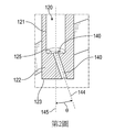
第1圖顯示了根據本揭露書的一個或多個實施例的安瓿的剖視圖;第2圖顯示了第1圖的放大區域2;第3圖顯示了根據本揭露書的一個或多個實施例的安瓿的局部橫截面;及第4圖顯示了根據本揭露書的一個或多個實施例的安瓿和管道的示意圖。
Figure 1 shows a cross-sectional view of an ampoule according to one or more embodiments of this disclosure; Figure 2 shows an enlarged
在附隨的圖式中,類似的部件及/或特徵可具有相同的元件符號。此外,相同類型的各種部件可藉由在元件符號之後用區分類似部件之間的破折號和第二符號來區分。若在說明書中僅使用第一元件符號,則實施方式適用於具有相同第一元件符號的任何一個相似部件,而不管第二元件符號如何。圖式中部件的交叉影線陰影意欲幫助視覺化不同的部分,且不一定指示不同的構造材料。 In the accompanying drawings, similar components and/or features may have the same symbol. In addition, various components of the same type can be distinguished by using a dash and a second symbol after the element symbol to distinguish between similar components. If only the first component symbol is used in the specification, the embodiment is applicable to any one similar component having the same first component symbol regardless of the second component symbol. The cross-hatched shading of the parts in the drawing is intended to help visualize the different parts, and does not necessarily indicate different construction materials.
在描述本發明的若干示例性實施例之前,應該理解本發明不限於以下的實施方式中闡述的構造或處理 步驟的細節。本發明能夠具有其他實施例並能夠以各種方式實施或執行。 Before describing several exemplary embodiments of the present invention, it should be understood that the present invention is not limited to the configuration or processing set forth in the following embodiments The details of the steps. The present invention can have other embodiments and can be implemented or executed in various ways.
本揭露書的一些實施例有利地提供具有比交叉流安瓿高的通量的安瓿。一些實施例有利地為安瓿提供通過液體前驅物不會起泡的氣流。一些實施例有利地提供了不與前驅物表面正交的氣流。 Some embodiments of the present disclosure advantageously provide ampoules with higher throughput than cross-flow ampoules. Some embodiments advantageously provide the ampoule with a gas flow that does not foam through the liquid precursor. Some embodiments advantageously provide an air flow that is not orthogonal to the precursor surface.
在一些實施例中,噴頭設置在安瓿的入口上,具有在其內的液體上成角度的複數個噴嘴。保持液體的水平與噴頭之間的距離,使得噴頭不浸沒在液體中。 In some embodiments, the spray head is disposed on the inlet of the ampoule, and has a plurality of nozzles angled on the liquid inside. Keep the distance between the level of the liquid and the nozzle so that the nozzle is not immersed in the liquid.
第1圖顯示了用於半導體製造試劑的安瓿100。術語「前驅物」用以描述安瓿100的內容物,且指的是流到處理環境中的任何試劑。
Figure 1 shows an
安瓿100包括容器110,容器110具有封閉空腔118的底部112、側壁114和蓋子116。入口埠120和出口埠130與空腔118流體連通。
The
入口埠120通常構造成允許連接到氣體源且可具有合適的螺紋或密封連接。入口埠120(如第1和2圖所示)具有通道121,通道121具有界定通道121的橫截面寬度的內徑。通道121具有可彎曲,漸縮,或達到平坦端的底端125。
The
入口埠120在位於空腔118內的入口埠120的端部123上具有噴頭122。噴頭122是入口埠120的位於通道121的底端125與入口埠120的端部123之間的部分。噴頭122包含至少兩個成角度的噴嘴140,以引導氣
流141。噴頭122中的噴嘴140的數量可在約2到約24的範圍中,或在約2至約18的範圍中,或在約2至約12的範圍中,或在約2至約10的範圍中,或在約2至約8的範圍中,或在約2至約6的範圍中,或在約2至約4的範圍中。在一些實施例中,在噴頭122中有三個噴嘴140。
The
噴嘴140被配置為提供相對於與安瓿100內的液體150的表面151正交的線而量測的成角度的氣流141。參照第2和3圖,每個噴嘴140具有相對於與表面151正交的線145成角度θ的軸線144。
The
角度θ可為不垂直於液體150的表面151的任何合適的角度。每個噴嘴140可具有與任何其他噴嘴140不同的角度θ。在一些實施例中,角度θ相對於與表面151正交的線145大於1°,2°,3°或4°。在一些實施例中,角度θ在約2°至約25°的範圍中,或在約2.5°至約15°的範圍中,或在約3°至約12°的範圍中,或在約4°至約10°的範圍中,或在約5°至約7°的範圍中。在一些實施例中,離開噴嘴的氣流不垂直於容器110內的液體150的表面151。
The angle θ may be any suitable angle that is not perpendicular to the
出口埠130也與容器110中的空腔118流體連通。出口埠130通常被配置為能夠連接到管線,以允許離開容器110的氣體流動到處理腔室(或其他部件)。出口埠130可具有螺紋連接,以允許氣體管線連接。
The
在一些實施例中,如第1圖所示,蓋子116是與底部112和側壁114分開的部件。蓋子116可使用可移
除的螺栓通過適當成形的開口160而連接到容器110的側壁114。開口160可具有螺紋部分,以允許方便連接螺栓。螺栓可被移除,以允許蓋子116從容器110移除,使得容器110中的前驅物可被改變或添加。在一些實施例中,容器110包括定位在蓋子116和側壁114之間的O形環162,以形成流體緊密密封。
In some embodiments, as shown in FIG. 1, the
在一些實施例中,如第4圖所示,蓋子116可與容器110的側壁114和底部112一體形成。不同的管道配置可連接到蓋子116,以允許安瓿100被添加到處理腔室。在一些實施例中,入口管線170連接到入口埠120。入口閥172可定位在氣體源175和入口埠120之間的入口管線170上。入口閥172可與蓋子116一體地形成或作為單獨的部件連接到蓋子116。出口管線180可連接到出口埠130。一些實施例的出口管線180包括位於出口埠130和處理腔室185之間的出口閥182。入口閥172和出口閥182可用以隔離安瓿100,使得空腔118的內容物與容器110外部的環境隔離。在一些實施例中,沿著入口管線170及/或出口管線180存在多個閥。閥172、182可為手動閥或氣動閥。
In some embodiments, as shown in FIG. 4, the
在一些實施例中,安瓿100包括空腔118內的液體150。液體150可為與半導體製造處理一起使用的前驅物。一些實施例的液體150包含二鈷六羰基三級丁基乙炔(CCTBA)。
In some embodiments, the
參照第3圖,噴頭122到液體150的表面151的距離D可能隨著時間和前驅物的使用而變化。當使用前驅物時,容器110內的容積將減小,使得距離D增加。距離D足以防止噴頭122接觸或浸沒在液體150中。
Referring to Figure 3, the distance D from the
在一些實施例中,通過入口埠120和噴頭122的氣流141足以擾動液體前驅物的液體/氣體界面而不起泡。在一些實施例中,擾動液體/氣體界面在液體150的表面151中形成凹坑153。凹坑153可具有高達約3mm的深度。在一些實施例中,凹坑具有大於或等於大約0.1mm的深度(從表面151量測)。在一些實施例中,凹坑153具有小於或等於約2.5mm,2mm,1.5mm,1mm,或0.5mm的深度。氣流141可在處理期間隨著液體150的水平降低而調節,以保持液體/氣體界面的充分擾動。一些實施例的氣流141具有足以防止液體150在出口埠130處冷凝的最大速度。
In some embodiments, the
貫穿這份說明書對「一個實施例」,「某些實施例」,「一個或多個實施例」或「實施例」的引用意味著結合該實施例而描述的特定特徵,結構,材料,或特性被包括在本發明的至少一個實施例中。因此,貫穿這份說明書各處出現的諸如「在一個或多個實施例中」,「在某些實施例中」,「在一個實施例中」或「在實施例中」的短語不一定代表本發明的相同實施例。此外,特定特徵,結構,材料,或特性可以任何合適的方式在一個或多個實施例中組合。 Throughout this specification, references to "one embodiment," "certain embodiments," "one or more embodiments," or "an embodiment" mean specific features, structures, materials, or The characteristics are included in at least one embodiment of the present invention. Therefore, phrases such as "in one or more embodiments", "in certain embodiments", "in one embodiment" or "in an embodiment" appearing throughout this specification are not necessarily Represents the same embodiment of the present invention. In addition, specific features, structures, materials, or characteristics may be combined in one or more embodiments in any suitable manner.
儘管已經參考特定實施例描述了於此的本發明,但應該理解這些實施例僅僅是對本發明的原理和應用的說明。對於熟悉本領域者來說顯而易見的是,在不背離本發明的精神和範圍的情況下,可對本發明的方法和設備進行各種修改和變化。因此,本發明意欲包括在所附隨的申請專利範圍及其等效元件的範圍內的修改和變化。 Although the present invention has been described herein with reference to specific embodiments, it should be understood that these embodiments are merely illustrative of the principles and applications of the present invention. It is obvious to those skilled in the art that various modifications and changes can be made to the method and device of the present invention without departing from the spirit and scope of the present invention. Therefore, the present invention intends to include modifications and changes within the scope of the attached patent application and its equivalent elements.
2:放大區域 2: zoom in area
100:安瓿 100: Ampoule
110:容器 110: container
112:底部 112: bottom
114:側壁 114: sidewall
116:蓋子 116: Lid
118:空腔 118: Cavity
120:入口埠 120: entrance port
121:通道 121: Channel
122:噴頭 122: print head
123:端部 123: End
130:出口埠 130: exit port
140:噴嘴 140: Nozzle
160:開口 160: opening
162:O形環 162: O-ring
Claims (30)
Applications Claiming Priority (2)
| Application Number | Priority Date | Filing Date | Title |
|---|---|---|---|
| US201762466669P | 2017-03-03 | 2017-03-03 | |
| US62/466,669 | 2017-03-03 |
Publications (2)
| Publication Number | Publication Date |
|---|---|
| TW201834935A TW201834935A (en) | 2018-10-01 |
| TWI719284B true TWI719284B (en) | 2021-02-21 |
Family
ID=63356839
Family Applications (1)
| Application Number | Title | Priority Date | Filing Date |
|---|---|---|---|
| TW107106966A TWI719284B (en) | 2017-03-03 | 2018-03-02 | Ampoule for semiconductor manufacturing precursor and ampoule for semiconductor precursor liquid |
Country Status (7)
| Country | Link |
|---|---|
| US (2) | US11059061B2 (en) |
| EP (1) | EP3589776A4 (en) |
| JP (2) | JP7289789B2 (en) |
| KR (3) | KR20240005188A (en) |
| CN (2) | CN110475905B (en) |
| TW (1) | TWI719284B (en) |
| WO (1) | WO2018160931A1 (en) |
Families Citing this family (5)
| Publication number | Priority date | Publication date | Assignee | Title |
|---|---|---|---|---|
| JP7267088B2 (en) * | 2019-05-10 | 2023-05-01 | 東京エレクトロン株式会社 | Tanks, substrate processing equipment, and methods of using tanks |
| KR102732061B1 (en) * | 2019-05-31 | 2024-11-18 | 어플라이드 머티어리얼스, 인코포레이티드 | Methods and systems for forming films on substrates |
| US11502160B2 (en) * | 2020-03-02 | 2022-11-15 | Taiwan Semiconductor Manufacturing Co., Ltd. | Method and system for forming metal-insulator-metal capacitors |
| US11587873B2 (en) | 2020-05-06 | 2023-02-21 | Applied Materials, Inc. | Binary metal liner layers |
| US11270911B2 (en) | 2020-05-06 | 2022-03-08 | Applied Materials Inc. | Doping of metal barrier layers |
Citations (1)
| Publication number | Priority date | Publication date | Assignee | Title |
|---|---|---|---|---|
| US20160333477A1 (en) * | 2015-05-13 | 2016-11-17 | Air Products And Chemicals, Inc. | Container for chemical precursors in a deposition process |
Family Cites Families (19)
| Publication number | Priority date | Publication date | Assignee | Title |
|---|---|---|---|---|
| JPH06295862A (en) | 1992-11-20 | 1994-10-21 | Mitsubishi Electric Corp | Compound semiconductor fabrication system and organic metal material vessel |
| JP2001274145A (en) * | 2000-03-24 | 2001-10-05 | Mitsubishi Electric Corp | Liquid source vaporizer, semiconductor device, and method of manufacturing semiconductor device |
| US7118783B2 (en) * | 2002-06-26 | 2006-10-10 | Micron Technology, Inc. | Methods and apparatus for vapor processing of micro-device workpieces |
| US7186385B2 (en) | 2002-07-17 | 2007-03-06 | Applied Materials, Inc. | Apparatus for providing gas to a processing chamber |
| US7156380B2 (en) | 2003-09-29 | 2007-01-02 | Asm International, N.V. | Safe liquid source containers |
| US20050249873A1 (en) | 2004-05-05 | 2005-11-10 | Demetrius Sarigiannis | Apparatuses and methods for producing chemically reactive vapors used in manufacturing microelectronic devices |
| JP4553245B2 (en) * | 2004-09-30 | 2010-09-29 | 東京エレクトロン株式会社 | Vaporizer, film forming apparatus and film forming method |
| JP4299286B2 (en) * | 2005-10-06 | 2009-07-22 | 東京エレクトロン株式会社 | Vaporization apparatus, film forming apparatus, and vaporization method |
| US7464917B2 (en) * | 2005-10-07 | 2008-12-16 | Appiled Materials, Inc. | Ampoule splash guard apparatus |
| US7967911B2 (en) * | 2006-04-11 | 2011-06-28 | Applied Materials, Inc. | Apparatus and methods for chemical vapor deposition |
| KR100980729B1 (en) * | 2006-07-03 | 2010-09-07 | 주식회사 야스 | Multi-nozzle evaporation source for deposition process |
| US8518483B2 (en) * | 2007-01-29 | 2013-08-27 | Praxair Technology, Inc. | Diptube apparatus and method for delivering vapor phase reagent to a deposition chamber |
| US8146896B2 (en) | 2008-10-31 | 2012-04-03 | Applied Materials, Inc. | Chemical precursor ampoule for vapor deposition processes |
| US20100119734A1 (en) | 2008-11-07 | 2010-05-13 | Applied Materials, Inc. | Laminar flow in a precursor source canister |
| JP5589873B2 (en) | 2011-01-31 | 2014-09-17 | 東京エレクトロン株式会社 | Vaporization apparatus and film forming apparatus |
| JP5728772B2 (en) * | 2011-05-31 | 2015-06-03 | 株式会社ブイ・テクノロジー | Raw material gas generator |
| JP5761067B2 (en) | 2012-02-13 | 2015-08-12 | 東京エレクトロン株式会社 | Gas supply device and heat treatment device |
| KR101389011B1 (en) * | 2012-03-28 | 2014-04-24 | 주식회사 유니텍스 | Source container and reactor for vapor phase deposition |
| US10480070B2 (en) | 2016-05-12 | 2019-11-19 | Versum Materials Us, Llc | Delivery container with flow distributor |
-
2018
- 2018-03-02 TW TW107106966A patent/TWI719284B/en active
- 2018-03-02 KR KR1020237044558A patent/KR20240005188A/en not_active Ceased
- 2018-03-02 EP EP18760987.0A patent/EP3589776A4/en active Pending
- 2018-03-02 KR KR1020197028275A patent/KR20190112212A/en not_active Ceased
- 2018-03-02 US US15/910,398 patent/US11059061B2/en active Active
- 2018-03-02 CN CN201880020038.1A patent/CN110475905B/en active Active
- 2018-03-02 KR KR1020217038623A patent/KR20210148405A/en not_active Ceased
- 2018-03-02 WO PCT/US2018/020601 patent/WO2018160931A1/en not_active Ceased
- 2018-03-02 CN CN202210670164.XA patent/CN115044888A/en active Pending
- 2018-03-02 JP JP2019548066A patent/JP7289789B2/en active Active
-
2021
- 2021-06-17 US US17/350,353 patent/US11628456B2/en active Active
-
2022
- 2022-02-24 JP JP2022026852A patent/JP7788087B2/en active Active
Patent Citations (1)
| Publication number | Priority date | Publication date | Assignee | Title |
|---|---|---|---|---|
| US20160333477A1 (en) * | 2015-05-13 | 2016-11-17 | Air Products And Chemicals, Inc. | Container for chemical precursors in a deposition process |
Also Published As
| Publication number | Publication date |
|---|---|
| EP3589776A4 (en) | 2020-11-11 |
| US11628456B2 (en) | 2023-04-18 |
| JP2022075691A (en) | 2022-05-18 |
| US20210308703A1 (en) | 2021-10-07 |
| EP3589776A1 (en) | 2020-01-08 |
| CN110475905B (en) | 2025-07-15 |
| JP2020509239A (en) | 2020-03-26 |
| KR20210148405A (en) | 2021-12-07 |
| JP7289789B2 (en) | 2023-06-12 |
| CN110475905A (en) | 2019-11-19 |
| WO2018160931A1 (en) | 2018-09-07 |
| CN115044888A (en) | 2022-09-13 |
| KR20190112212A (en) | 2019-10-02 |
| US20180250695A1 (en) | 2018-09-06 |
| JP7788087B2 (en) | 2025-12-18 |
| TW201834935A (en) | 2018-10-01 |
| US11059061B2 (en) | 2021-07-13 |
| KR20240005188A (en) | 2024-01-11 |
Similar Documents
| Publication | Publication Date | Title |
|---|---|---|
| TWI719284B (en) | Ampoule for semiconductor manufacturing precursor and ampoule for semiconductor precursor liquid | |
| US11166441B2 (en) | Vapor delivery container with flow distributor | |
| TWI467104B (en) | Isolation valve with corrosion protected and heat transfer enhanced valve actuator and closure apparatus and method | |
| KR100905569B1 (en) | High flow volume distribution head with seal inspection and low foam return line | |
| KR101697205B1 (en) | Horizontal type chamber assembly for treating substrate | |
| KR20170067827A (en) | Atomic layer deposition chamber with thermal lid | |
| JP5086237B2 (en) | Large capacity fluid distribution system | |
| US11578406B2 (en) | Ampoule for a semiconductor manufacturing precursor | |
| TWI675120B (en) | Aerosol-free vessel and method for bubbling chemical precursors in a deposition process | |
| TWI878376B (en) | High temperature dual channel showerhead | |
| JP2000346238A5 (en) | Vacuum valves and vacuum processing equipment | |
| US9512518B2 (en) | Apparatus for treating a gas stream | |
| CN114277358A (en) | Liquid source bottle and semiconductor process equipment | |
| US12331849B2 (en) | Diaphragm valves | |
| KR100837303B1 (en) | Gate Valves for Semiconductor and LC Vacuum Equipment | |
| KR20230129810A (en) | Process chamber for semiconductor | |
| KR20250121578A (en) | Ampoules for semiconductor manufacturing precursors |