TWI712062B - Key and electronic device with same - Google Patents
Key and electronic device with same Download PDFInfo
- Publication number
- TWI712062B TWI712062B TW106124035A TW106124035A TWI712062B TW I712062 B TWI712062 B TW I712062B TW 106124035 A TW106124035 A TW 106124035A TW 106124035 A TW106124035 A TW 106124035A TW I712062 B TWI712062 B TW I712062B
- Authority
- TW
- Taiwan
- Prior art keywords
- key
- button
- cap
- waterproof ring
- electronic device
- Prior art date
Links
Images


Landscapes
- Push-Button Switches (AREA)
- Switch Cases, Indication, And Locking (AREA)
Abstract
Description
本發明涉及一種按鍵及具有該按鍵的電子裝置 The invention relates to a button and an electronic device with the button
近幾年來,消費者對防水手機的需求日漸增加,也將防水功能視為購入新機的條件之一。另外,對防水手機的防水效果也提出了更高的要求。目前,市場上的防水設計主要是在按鍵和開關之間隔著一片橡膠膜以達到防水的效果。但是,該橡膠膜的設置會對使用者的按壓手感產生間接的影響。 In recent years, consumers' demand for waterproof mobile phones has increased day by day, and they also regard waterproof function as one of the conditions for purchasing new phones. In addition, higher requirements are put forward for the waterproof effect of waterproof mobile phones. At present, the waterproof design on the market is mainly based on a rubber membrane between the button and the switch to achieve the waterproof effect. However, the arrangement of the rubber film will have an indirect effect on the user's pressing feel.
有鑑於此,有必要提供一種按壓舒適的按鍵。 In view of this, it is necessary to provide a button that is comfortable to press.
本發明還提供了一種具有該按鍵的電子裝置。 The invention also provides an electronic device with the button.
一種按鍵,設置於電子裝置的殼體上,所述按鍵包括鍵帽、按鍵支架、防水圈及按鍵柱,所述按鍵支架卡接於所述鍵帽,所述按鍵支架上設置有穿孔,所述防水圈設置於所述穿孔內,所述按鍵柱設置於所述防水圈內並抵持於所述鍵帽。 A key is arranged on a housing of an electronic device. The key includes a key cap, a key support, a waterproof ring, and a key post. The key support is clipped to the key cap, and the key support is provided with perforations. The waterproof ring is arranged in the perforation, and the key column is arranged in the waterproof ring and resists the key cap.
一種電子裝置,包括一殼體,所述電子裝置還包括至少一個所述按鍵,其中所述按鍵設置於所述殼體上。 An electronic device includes a housing, the electronic device further includes at least one of the keys, wherein the keys are arranged on the housing.
綜上所述,所述按鍵設置於所述電子裝置的殼體外表面。藉由在所述按鍵支架的穿孔上設置防水圈,以得到具有防水和防塵功能的按鍵。同時,所述按鍵安裝程式簡單,而且按壓的手感也更佳。 In summary, the button is arranged on the outer surface of the housing of the electronic device. A waterproof ring is provided on the perforation of the button bracket to obtain a button with waterproof and dustproof functions. At the same time, the button installation program is simple, and the pressing feel is better.
10:殼體 10: Shell
101:安裝槽 101: installation slot
1011:通孔 1011: Through hole
1013:螺絲 1013: screw
20:按鍵 20: Button
201:鍵帽 201: keycap
2011:第一凹槽 2011: first groove
2013:第二凹槽 2013: second groove
202:凸出部 202: protruding part
203:按鍵支架 203: Button bracket
2031:穿孔 2031: Piercing
2033:貫穿螺孔 2033: Through screw hole
204:卡槽 204: card slot
205a:按鍵柱 205a: Button column
205b:按鍵柱 205b: Button column
2051:柱體 2051: cylinder
2053:柱體 2053: cylinder
2052:帽體 2052: cap body
2054:帽體 2054: Cap body
206:卡條部 206: Card section
207:防水圈 207: Waterproof ring
30:按鍵 30: Button
301:鍵帽 301: keycap
303:按鍵支架 303: Button bracket
305:按鍵柱 305: Button column
40:開關模組 40: switch module
401:開關 401: switch
402:開關 402: Switch
403:開關 403: switch
100:電子裝置 100: electronic device
圖1為本發明較佳實施例的具有按鍵的電子裝置。 FIG. 1 is an electronic device with buttons according to a preferred embodiment of the present invention.
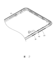
圖2為圖1所示具有按鍵的電子裝置的一視角的部分結構示意圖。 FIG. 2 is a schematic view of a partial structure of the electronic device with buttons shown in FIG. 1 from a perspective.
圖3為圖1所示具有按鍵的電子裝置的另一視角的部分結構示意圖。 FIG. 3 is a schematic diagram of a partial structure of the electronic device with buttons shown in FIG. 1 from another perspective.
圖4為圖2所示具有按鍵的電子裝置的分解圖。 Fig. 4 is an exploded view of the electronic device with buttons shown in Fig. 2.
圖5為圖3所示具有按鍵的電子裝置另一視角的分解圖。 FIG. 5 is an exploded view of the electronic device with buttons shown in FIG. 3 from another perspective.
圖6為圖1所示具有按鍵的電子裝置的部分結構剖視圖。 6 is a cross-sectional view of a partial structure of the electronic device with buttons shown in FIG. 1.
下面將結合本發明實施例中的附圖,對本發明實施例中的技術方案進行清楚、完整地描述。顯然,所描述的實施例僅是本發明一部分實施例,而不是全部的實施例。基於本發明中的實施例,本領域普通技術人員在沒有做出創造性勞動前提下所獲得的所有其他實施例,都屬於本發明保護的範圍。 The technical solutions in the embodiments of the present invention will be clearly and completely described below in conjunction with the drawings in the embodiments of the present invention. Obviously, the described embodiments are only a part of the embodiments of the present invention, rather than all the embodiments. Based on the embodiments of the present invention, all other embodiments obtained by those of ordinary skill in the art without creative work shall fall within the protection scope of the present invention.
除非另有定義,本文所使用的所有的技術和科學術語與屬於本發明的技術領域的技術人員通常理解的含義相同。本文中在本發明的說明書中所使用的術語只是為了描述具體的實施例的目的,不是旨在限制本發明。 Unless otherwise defined, all technical and scientific terms used herein have the same meaning as commonly understood by those skilled in the technical field of the present invention. The terms used in the description of the present invention herein are only for the purpose of describing specific embodiments, and are not intended to limit the present invention.
下面結合附圖,對本發明的一些實施方式作詳細說明。在不衝突的情況下,下述的實施例及實施例中的特徵可以相互組合。 Hereinafter, some embodiments of the present invention will be described in detail with reference to the accompanying drawings. In the case of no conflict, the following embodiments and features in the embodiments can be combined with each other.
參閱圖1,本發明提供了一較佳實施例的電子裝置100。所述電子裝置100可為各種帶有殼體的電子裝置,如手機、平板電腦、智慧手錶等。所述電子裝置100包括殼體10及設置於所述殼體10上的按鍵。其中,所述按鍵部分露出於所述殼體10外表面。
Referring to FIG. 1, the present invention provides an
請一併參閱圖2和圖3,在本實施例中,所述電子裝置100還包括開關模組40。所述開關模組40安裝於所述殼體10內。所述開關模組40與所述電子裝置100內的各元件電連接。所述開關模組40亦與所述按鍵連接,以藉由所述按鍵的按壓操作控制所述開關模組40連接的電子裝置100內的各元件。
Please refer to FIGS. 2 and 3 together. In this embodiment, the
請一併參閱圖4、圖5和圖6,所述殼體10上開設有安裝槽101。所述安裝槽101的形狀與所述按鍵形狀一致。所述按鍵容置於所述安裝槽101,並部分露出於所述安裝槽101,以方便外界的按壓操作。在本實施例中,所述安裝槽101由一類似的圓角矩形的底壁及一周壁構成。
Please refer to FIG. 4, FIG. 5 and FIG. 6 together, the
可以理解,所述電子裝置100上的按鍵數量可根據實際需要進行調整。如此,所述電子裝置100的按鍵數可為一個、兩個、三個等。在本實施例中,所述電子裝置100具有兩個按鍵。為了方便描述,在下述的描述中將所述兩個按鍵定義為按鍵20和按鍵30。
It can be understood that the number of buttons on the
所述按鍵20包括鍵帽201、按鍵支架203和按鍵柱205a和按鍵柱205b。對應所述按鍵柱205a和按鍵柱205b,所述開關模組40包括開關401和開關402。其中,所述按鍵柱205a和按鍵柱205b分別對應所述開關401和開關402設置。
The key 20 includes a
所述鍵帽201部分露出於所述殼體10外表面。所述露出部分可方便使用者感知按鍵20所設置的位置,也便於外界的按壓操作。所述鍵帽201本體兩端垂直方向分別延伸出一凸出部202。沿著所述凸出部202本體垂直方向開一凹形的卡槽204。所述卡槽204用以卡接所述按鍵支架203。所述鍵帽201本體靠近所述凸出部202處分別設置第一凹槽2011。所述鍵帽201本體靠近所述第一凹槽2011處分別設置第二凹槽2013。
The
所述按鍵支架203用以固定所述鍵帽201。所述按鍵支架203與所述鍵帽201形狀大致相似。沿著所述按鍵支架203本體兩端水準方向分別延伸出一卡條部206。所述卡條部206卡接於所述卡槽204,從而將所述鍵帽201與所述按鍵支架203組裝在一起。
The
所述按鍵支架203本體對應所述第一凹槽2011設置有穿孔2031。所述穿孔2031貫穿所述按鍵支架203。所述按鍵支架203本體對應所述第二凹槽2013設置有貫穿螺孔2033。相應的,所述安裝槽101的底壁設置與所述穿孔2031
及所述貫穿螺孔2033對應的通孔1011。如此,於所殼體10內部將螺絲1013依次穿過所述通孔1011和所述貫穿螺孔2033,以將所述按鍵支架203固定於所述電子裝置100的殼體10上,從而將所述按鍵20固定於所述電子裝置100的殼體10上。其中,所述鍵帽201及所述殼體10完全包覆所述按鍵支架203。較佳的,在本實施例中,所述螺絲1013對應所述第二凹槽2013設置,但不接觸所述第二凹槽2013,以避免鍵帽201下壓時由於螺絲1013的抵持影響鍵帽201的下壓操作。
The body of the
所述按鍵柱205a和按鍵柱205b大體上均呈一T字形。所述按鍵柱205a和按鍵柱205b的主體分別為柱體2051和柱體2053。所述柱體2051其中一端設置有帽體2052。所述柱體2053其中一端設置有帽體2054。所述帽體2052和帽體2054分別相對所述柱體2051和柱體2053垂直設置。所述按鍵柱205a的柱體2051和按鍵柱205b的柱體2053同時穿過依次對應的所述通孔1011和所述穿孔2031,並抵持於所述鍵帽201上對應的所述第一凹槽2011。所述按鍵柱205a的帽體2052和按鍵柱205b的帽體2054分別抵持於所述開關401和開關402。如此,當外界對所述鍵帽201的一端進行按壓操作時,就會帶動抵持於所述鍵帽201上的按鍵柱205a/按鍵柱205b以抵持並觸發所述開關401/開關402。
The
在本實施例中,所述按鍵20還包括防水圈207。所述防水圈207為環狀結構。所述防水圈207由彈性材料製成,如橡膠等。所述防水圈207設置於所述按鍵支架203的穿孔2031內。所述防水圈207的外徑等於所述穿孔2031的孔徑,以將所述防水圈207設置於所述穿孔2031內。所述防水圈207的內徑略小於所述按鍵柱205a/按鍵柱205b的柱體2051/柱體2053的直徑,使得所述防水圈207的內表面可完全貼在所述柱體2051/柱體2053的外周面。同時,所述防水圈207受到所述柱體2051/柱體2053的擠壓而完全貼在所述穿孔2031的內表面,從而達到防水、防塵的效果。
In this embodiment, the
在其他實施例中,為了防止防水圈207受擠壓而脫離所述穿孔2031,以將所述穿孔2031兩端設置大小不一的孔徑。其中,所述穿孔2031遠離所述鍵帽201端的孔徑略大於靠近所述鍵帽201端的孔徑。所述防水圈207設置於所述穿孔2031孔徑略大的一端。
In other embodiments, in order to prevent the
當然,也可於所述貫穿螺孔2033中設置所述防水圈207以防塵和防水。
Of course, the
在本實施例中,所述按鍵柱205a和按鍵柱205b分別位於所述鍵帽201的兩端。用戶可分別對所述鍵帽201的兩端進行按壓操作,以分別帶動按鍵柱205a和按鍵柱205b抵持並觸發對應的開關401和開關402,進而啟動所述電子裝置100中不同功能。另外,按鍵20可以是音量鍵,所述功能可以是增加音量與降低音量。
In this embodiment, the
所述按鍵30包括鍵帽301、按鍵支架303和按鍵柱305。對應所述按鍵柱305,所述開關模組40還包括開關403。其中,所述按鍵柱305對應所述開關403設置。所述按鍵30與所述按鍵20的結構差別在於,所述按鍵30僅有一個按鍵柱305。用戶僅需按壓所述鍵帽301,以帶到所述按鍵柱305抵持並觸發所述開關403,進而啟動所述電子裝置100中的其他功能。
The key 30 includes a
在其他實施例中,所述電子裝置100上的按鍵可根據實際需要安裝如按鍵20和/或按鍵30。
In other embodiments, the buttons on the
以按鍵20為例,將所述按鍵20安裝於所述電子裝置100的工序為:
Taking the
步驟一:將所述按鍵支架203上的卡條部206卡接於所述鍵帽201上的卡槽204,使得所述鍵帽201與所述按鍵支架203組裝在一起。
Step 1: Clip the
步驟二:將防水圈207設置於所述穿孔2031。
Step 2: Set the
步驟三:將組裝成一體的鍵帽201和按鍵支架203放入所述安裝槽101中。
Step 3: Put the assembled
步驟四:將螺絲1013依次穿過所述殼體10的通孔1011與所述按鍵支架203的貫穿螺孔2033,從而將所述殼體10與所述按鍵支架203固定在一起。
Step 4: Pass the
步驟五:所述按鍵柱205a的柱體2051和按鍵柱205b的柱體2053同時穿過依次對應的所述通孔1011和所述穿孔2031,並抵持於所述鍵帽201上對應的的第一凹槽2011。所述按鍵柱205a的帽體2052和所述按鍵柱205b的帽體2054分別抵持於所述開關401和開關402。如此,所述按鍵20即已安裝於所述電子裝置100。
Step 5: The
綜上所述,所述按鍵設置於所述電子裝置100的殼體10外表面。藉由在所述按鍵支架203的穿孔2031及貫穿螺孔2033上設置防水圈207,以得到具有防水和防塵功能的按鍵。同時,所述按鍵安裝程式簡單,而且按壓的手感也更佳。
In summary, the button is arranged on the outer surface of the
以上實施例僅用以說明本發明的技術方案而非限制,儘管參照較佳實施例對本發明進行了詳細的說明,本領域的普通技術人員應當理解,可以對本發明的技術方案進行修改或等同替換,而不脫離本發明技術方案的精神和實質。 The above embodiments are only used to illustrate the technical solutions of the present invention and not to limit them. Although the present invention has been described in detail with reference to the preferred embodiments, those of ordinary skill in the art should understand that the technical solutions of the present invention can be modified or equivalently replaced. , Without departing from the spirit and essence of the technical solution of the present invention.
10:殼體 10: Shell
101:安裝槽 101: installation slot
1013:螺絲 1013: screw
201:鍵帽 201: keycap
202:凸出部 202: protruding part
203:按鍵支架 203: Button bracket
2031:穿孔 2031: Piercing
2033:貫穿螺孔 2033: Through screw hole
204:卡槽 204: card slot
205a:按鍵柱 205a: Button column
205b:按鍵柱 205b: Button column
2051:柱體 2051: cylinder
2053:柱體 2053: cylinder
2052:帽體 2052: cap body
2054:帽體 2054: Cap body
206:卡條部 206: Card section
207:防水圈 207: Waterproof ring
301:鍵帽 301: keycap
303:按鍵支架 303: Button bracket
305:按鍵柱 305: Button column
40:開關模組 40: switch module
401:開關 401: switch
402:開關 402: Switch
403:開關 403: switch
Claims (8)
Priority Applications (1)
| Application Number | Priority Date | Filing Date | Title |
|---|---|---|---|
| TW106124035A TWI712062B (en) | 2017-07-18 | 2017-07-18 | Key and electronic device with same |
Applications Claiming Priority (1)
| Application Number | Priority Date | Filing Date | Title |
|---|---|---|---|
| TW106124035A TWI712062B (en) | 2017-07-18 | 2017-07-18 | Key and electronic device with same |
Publications (2)
| Publication Number | Publication Date |
|---|---|
| TW201909214A TW201909214A (en) | 2019-03-01 |
| TWI712062B true TWI712062B (en) | 2020-12-01 |
Family
ID=66590069
Family Applications (1)
| Application Number | Title | Priority Date | Filing Date |
|---|---|---|---|
| TW106124035A TWI712062B (en) | 2017-07-18 | 2017-07-18 | Key and electronic device with same |
Country Status (1)
| Country | Link |
|---|---|
| TW (1) | TWI712062B (en) |
Families Citing this family (1)
| Publication number | Priority date | Publication date | Assignee | Title |
|---|---|---|---|---|
| TWI812452B (en) * | 2022-09-05 | 2023-08-11 | 和碩聯合科技股份有限公司 | Button module |
Citations (4)
| Publication number | Priority date | Publication date | Assignee | Title |
|---|---|---|---|---|
| CN102709086A (en) * | 2012-05-28 | 2012-10-03 | 鸿富锦精密工业(深圳)有限公司 | Press key and electronic device with same |
| CN104534295A (en) * | 2015-01-19 | 2015-04-22 | 李文杰 | Electric torch capable of achieving dimming conveniently and rapidly |
| CN205487860U (en) * | 2016-03-31 | 2016-08-17 | 上海鼎为电子科技(集团)有限公司 | Lateral push button structure of cell phone |
| TW201643913A (en) * | 2015-03-03 | 2016-12-16 | 賓工程工廠公司 | Micro push-button assembly |
-
2017
- 2017-07-18 TW TW106124035A patent/TWI712062B/en active
Patent Citations (4)
| Publication number | Priority date | Publication date | Assignee | Title |
|---|---|---|---|---|
| CN102709086A (en) * | 2012-05-28 | 2012-10-03 | 鸿富锦精密工业(深圳)有限公司 | Press key and electronic device with same |
| CN104534295A (en) * | 2015-01-19 | 2015-04-22 | 李文杰 | Electric torch capable of achieving dimming conveniently and rapidly |
| TW201643913A (en) * | 2015-03-03 | 2016-12-16 | 賓工程工廠公司 | Micro push-button assembly |
| CN205487860U (en) * | 2016-03-31 | 2016-08-17 | 上海鼎为电子科技(集团)有限公司 | Lateral push button structure of cell phone |
Also Published As
| Publication number | Publication date |
|---|---|
| TW201909214A (en) | 2019-03-01 |
Similar Documents
| Publication | Publication Date | Title |
|---|---|---|
| CN109273305B (en) | Key and electronic device with same | |
| CN107408358B (en) | Scroll type flexible display | |
| JP6945311B2 (en) | cover | |
| CN107835972B (en) | Reel type flexible input device | |
| CN102157286A (en) | Output and input system for electronic apparatus | |
| WO2015192473A1 (en) | Waterproof apparatus for terminal side-key, and terminal | |
| US20160135308A1 (en) | Protective case for electronic device | |
| US20130162541A1 (en) | Control key assembly for portable electronic device | |
| TWI712062B (en) | Key and electronic device with same | |
| CN108511242B (en) | a mobile terminal | |
| US9299511B2 (en) | Key assembly and electronic device | |
| JP2008187361A (en) | Portable radio terminal unit | |
| WO2019001465A1 (en) | Decorative component and electronic device | |
| CN211980469U (en) | Key structure and electronic equipment | |
| CN108565159B (en) | Key assembly and wearable equipment | |
| JP2014131088A (en) | Electronic apparatus | |
| CN202839381U (en) | Side-press button structure and handheld electronic device | |
| JP2016122605A (en) | External connection terminal section and electronic device including the same | |
| US20180262225A1 (en) | Protective case and electronic assembly | |
| CN108513184B (en) | Intelligent wearing device | |
| CN220935214U (en) | Electronic equipment protective housing | |
| JP2014099709A (en) | Portable terminal | |
| CN216291304U (en) | Wearable intelligent sound box | |
| CN107864578A (en) | Anti-loss device and its anti-scratch hand housing | |
| CN213124213U (en) | Key connection structure and electronic equipment |