TWI709939B - Displacement detection method and system - Google Patents
Displacement detection method and system Download PDFInfo
- Publication number
- TWI709939B TWI709939B TW107118689A TW107118689A TWI709939B TW I709939 B TWI709939 B TW I709939B TW 107118689 A TW107118689 A TW 107118689A TW 107118689 A TW107118689 A TW 107118689A TW I709939 B TWI709939 B TW I709939B
- Authority
- TW
- Taiwan
- Prior art keywords
- section
- displacement
- deformation
- time
- value
- Prior art date
Links
Images


Landscapes
- Length Measuring Devices With Unspecified Measuring Means (AREA)
- Testing Or Calibration Of Command Recording Devices (AREA)
Abstract
本發明係一種變位偵測方法及其系統,該變位偵測方法包括提供不相同之第一斷面及第二斷面,於該第一斷面設置複數個第一偵測裝置,且於該第二斷面設置複數個第二偵測裝置,以該些第一偵測裝置及該些第二偵測裝置定義一多面體;計算該多面體於第一時間之第一基準中心及於第二時間之第二基準中心;基於該第一基準中心及該第二基準中心,計算平移值及旋轉值;基於該平移值及該旋轉值,計算變形值;以及若該變形值不為零,該些第一偵測裝置及該些第二偵測裝置於該第二時間之位置,進行第三時間及第四時間的斷面測量,該斷面測量包含該第一斷面及該第二斷面的數量足以偵測斷面變形之非固定監測點的三維座標測量;基於該非固定監測點於該第三時間及該第四時間的坐標差異得到變位值,且計算該變位值之變位模態組成,變位模態包含剛體運動變位模態與變形變位模態。本發明能有效利用固定監測點位置確定並確實反映隧道區域行為。 The present invention is a displacement detection method and system thereof. The displacement detection method includes providing a first section and a second section that are different, and arranging a plurality of first detection devices on the first section, and A plurality of second detection devices are set on the second section, and a polyhedron is defined by the first detection devices and the second detection devices; the first reference center of the polyhedron at the first time and the first reference center at the first time are calculated Two time second reference centers; based on the first reference center and the second reference center, calculate the translation value and rotation value; based on the translation value and the rotation value, calculate the deformation value; and if the deformation value is not zero, The first detection devices and the second detection devices perform cross-sectional measurement at the third time and the fourth time at the position of the second time, and the cross-sectional measurement includes the first cross-section and the second The number of sections is sufficient to detect the three-dimensional coordinate measurement of the non-fixed monitoring point of the cross-section deformation; the displacement value is obtained based on the coordinate difference of the non-fixed monitoring point at the third time and the fourth time, and the displacement value is calculated It consists of displacement modes, which include rigid body movement displacement modes and deformation displacement modes. The invention can effectively use the fixed monitoring point position to determine and indeed reflect the behavior of the tunnel area.
Description
本發明是關於土木監測之領域,更特定而言是關於變位偵測方法及其系統。 The present invention relates to the field of civil engineering monitoring, and more specifically to a displacement detection method and system.
諸多可能造成隧道變位之因素,例如:地質因素、設計因素及施工因素等。而地質因素譬如地質或岩盤強度不足;設計因素譬如隧道選址不當或因滑動邊坡造成側向偏壓過大;施工因素譬如開炸方式不當或支撐不足,使岩體切離或鬆弛等諸多因素,若未及早察覺隧道之變位,將可能釀成非常大之災害。 Many factors that may cause the displacement of the tunnel, such as: geological factors, design factors, and construction factors. Geological factors such as geology or lack of strength of rock plates; design factors such as improper site selection of tunnels or excessive lateral bias due to sliding slopes; construction factors such as improper blasting methods or insufficient support, which cause the rock mass to cut away or relax, etc. , If the displacement of the tunnel is not detected early, it may cause a very serious disaster.
在隧道監測之先前技術中,係以監測斷面為單位,利用斷面上所有監測點回歸鉛直平面,並求出監測點在回歸平面之投影點,於回歸平面上定義局部坐標,計算所有投影點構成之形心作為斷面形心坐標。同斷面前後兩次監測形心位置差為斷面平移量,再將之分為回歸平面上的分量,稱其為平面上平移量;以及回歸平面以外的分量,稱作平面外平移量。將較後一次投影點坐標全數扣除平移量,使兩次監測的回歸平面上投影點形心重合,以各投影點相對於形心轉角的平均作為旋轉量,而後得到扣除平移量和旋轉量的回歸平面上變形量,作為監測斷面之變形量。 In the prior art of tunnel monitoring, the monitoring section is used as a unit, and all monitoring points on the section are used to return to the vertical plane, and the projection points of the monitoring points on the regression plane are calculated. The local coordinates are defined on the regression plane and all projections are calculated. The centroid formed by the points is used as the cross-section centroid coordinates. The difference between the two monitoring centroid positions before and after the same fault is the section translation, which is then divided into the components on the regression plane, which is called the on-plane translation; and the components outside the regression plane, are called the out-of-plane translation. The coordinate of the last projection point is deducted from the translation amount so that the centroids of the projection points on the two monitored regression planes coincide, and the average rotation angle of each projection point relative to the centroid is used as the amount of rotation, and then the translation amount and the amount of rotation are deducted The amount of deformation on the return plane is used as the amount of deformation of the monitored section.
惟先前技術之隧道變位解析方法計算監測斷面平移量、旋轉量與變形量時並未區隔固定監測點及非固定監測點,而是將監測斷面上所有監測點 以相同流程處理。固定監測點為以鋼釘或規標等標的物固定於隧道襯砌上之點位;非固定監測點係利用首次量測獲得坐標,於第二次之後監測時利用前後GPS控制點、導線控制點等進行儀器定位後,以放樣功能測得;固定監測點較非固定監測點可靠度高。此外,已知方法主要解算隧道監測斷面,僅可計算出在隧道監測斷面的回歸平面上之二維變形量,無法用於估計回歸平面外的三維變形。 However, the prior art tunnel displacement analysis method does not distinguish between fixed monitoring points and non-fixed monitoring points when calculating the translation, rotation, and deformation of the monitoring section, but all monitoring points on the monitoring section Follow the same process. Fixed monitoring points are points fixed on the tunnel lining with steel nails or standard objects; non-fixed monitoring points are used to obtain coordinates from the first measurement, and the front and rear GPS control points and wire control points are used for monitoring after the second time. After the instrument is positioned, it can be measured with the stakeout function; fixed monitoring points are more reliable than non-fixed monitoring points. In addition, the known method mainly calculates the tunnel monitoring section, and can only calculate the two-dimensional deformation on the regression plane of the tunnel monitoring section, and cannot be used to estimate the three-dimensional deformation outside the regression plane.
有鑑於此,本發明提出一種變位偵測方法及其系統,以解決先前技術之無法估計回歸平面外的三維變形的缺點。 In view of this, the present invention proposes a displacement detection method and system to solve the disadvantage of the prior art that the three-dimensional deformation outside the regression plane cannot be estimated.
本發明提供一種變位偵測方法,係包括:提供不相同之第一斷面及第二斷面,於該第一斷面設置複數個第一偵測裝置,且於該第二斷面設置複數個第二偵測裝置,以該些第一偵測裝置及該些第二偵測裝置定義一多面體;計算該多面體於第一時間之第一基準中心及於第二時間之第二基準中心;基於該第一基準中心及該第二基準中心,計算平移值及旋轉值;基於該平移值及該旋轉值,計算變形值;以及若該變形值不為零,該些第一偵測裝置及該些第二偵測裝置於該第二時間之位置進行第三時間及第四時間的斷面測量,該斷面測量包含該第一斷面及該第二斷面數量足以偵測斷面變形之非固定監測點的三維坐標測量;基於非固定監測點於該第三時間及該第四時間的坐標差異得到變位值,且計算該變位值之變位模態組成,變位模態包含剛體運動變位模態與變形變位模態。 The present invention provides a displacement detection method, which includes: providing a first section and a second section that are different, and arranging a plurality of first detecting devices on the first section, and arranging on the second section A plurality of second detecting devices define a polyhedron by the first detecting devices and the second detecting devices; calculating the first reference center of the polyhedron at the first time and the second reference center at the second time Calculate the translation value and the rotation value based on the first reference center and the second reference center; calculate the deformation value based on the translation value and the rotation value; and if the deformation value is not zero, the first detection devices And the second detecting devices perform section measurement at the third time and the fourth time at the position of the second time, and the section measurement includes the first section and the second section in sufficient quantity to detect sections Three-dimensional coordinate measurement of the deformed non-fixed monitoring point; based on the coordinate difference between the non-fixed monitoring point at the third time and the fourth time, the displacement value is obtained, and the displacement modal composition of the displacement value is calculated, the displacement mode The state includes rigid body motion displacement mode and deformation displacement mode.
本發明之變位偵測方法,其中,該些第一偵測裝置之數目為至少四個,該些第二偵測裝置之數目為至少四個,以定義該多面體至少為六面體。 In the displacement detection method of the present invention, the number of the first detection devices is at least four, and the number of the second detection devices is at least four to define the polyhedron as at least a hexahedron.
本發明之變位偵測方法,其中,該第一基準中心及該第二基準中心係該第一時間及該第二時間之該多面體的各投影面上之各平面基準中心。 In the displacement detection method of the present invention, the first reference center and the second reference center are each plane reference center on each projection surface of the polyhedron at the first time and the second time.
本發明之變位偵測方法,其中,基於該變形值以決定是否計算該多面體之絕對座標。 In the displacement detection method of the present invention, it is determined whether to calculate the absolute coordinates of the polyhedron based on the deformation value.
本發明之變位偵測方法,其中,該些第一偵測裝置及該些第二偵測裝置更包含全球定位系統之一部分單元以控制測量、導線控制測量、路線回歸或其組合,且偵測絕對座標。 In the displacement detection method of the present invention, the first detection devices and the second detection devices further include a part of a global positioning system for controlling measurement, wire control measurement, route return or a combination thereof, and detecting Measure absolute coordinates.
本發明之變位偵測方法,其中,該第一斷面及該第二斷面係以該些第一偵測裝置及該些第二偵測裝置為基準,以對該第一斷面及該第二斷面進行多點斷面測量,各斷面至少包含足以偵測該斷面變形之非固定監測點,用以偵測該斷面的變位,且計算該變位值之變位模態組成。 In the displacement detection method of the present invention, the first section and the second section are based on the first detection devices and the second detection devices, and the first section and The second section performs multi-point section measurement, and each section includes at least a non-fixed monitoring point sufficient to detect the deformation of the section to detect the displacement of the section and calculate the displacement of the displacement value Modal composition.
本發明之變位偵測方法,其中,該斷面測量的變位值係監測之該斷面上所有該非固定監測點於該第三時間與該第四時間之三維座標的差異值。 In the displacement detection method of the present invention, the displacement value measured on the section is the difference value of the three-dimensional coordinates of all the non-fixed monitoring points on the section monitored at the third time and the fourth time.
本發明之變位偵測方法,其中,該剛體運動變位模態包含水平平移變位模態、垂直平移變位模態與旋轉變位模態等變位模態,該變形變位模態包含斷面監測點相對於斷面形心放大或縮小之均勻變形模態,及相對於該斷面形心之變形為橢圓形變形模態,相對於該斷面形心之變形為三角形變形模態,相對於該斷面形心之變形為四邊形變形模態,相對於該斷面形心之變形為五邊形變形模態,乃至相對於該斷面形心之變形為多邊形變形模態之複數種變位模態。 The displacement detection method of the present invention, wherein the rigid body movement displacement mode includes a horizontal translation displacement mode, a vertical translation displacement mode, and a rotation displacement mode. The deformation displacement mode Including the uniform deformation mode where the cross-section monitoring point is enlarged or reduced relative to the cross-section centroid, and the deformation relative to the cross-section centroid is an elliptical deformation mode, and the deformation relative to the cross-section centroid is a triangular deformation mode The deformation relative to the cross-section centroid is a quadrilateral deformation mode, the deformation relative to the cross-section centroid is a pentagonal deformation mode, and even the deformation relative to the cross-section centroid is a polygonal deformation mode Multiple variant modes.
本發明另提供一種變位偵測系統,係包括:設置於第一斷面的複數個第一偵測裝置;設置於第二斷面的複數個第二偵測裝置,該些第一偵測裝置及該些第二偵測裝置定義一多面體,該第一斷面與該第二斷面不相同;以及處理裝置或處理單元,該處理裝置係與該些第一偵測裝置及該些第二偵測裝置耦接,該處理單元係至少設置於該些第一偵測裝置及該些第二偵測裝置之其中之一且其他之該第一偵測裝置及該第二偵測裝置至少與該處理單元耦接,其 中,該處理裝置或該處理單元計算該多面體於第一時間之第一基準中心及於第二時間之第二基準中心,且其後基於該第一基準中心及該第二基準中心計算平移值及旋轉值,然後基於該平移值及該旋轉值計算變形值,並於該變形值不為零時,令該些第一偵測裝置及該些第二偵測裝置於該第二時間之位置進行第三時間及第四時間的斷面測量,該斷面測量包含該第一斷面及該第二斷面的數量足以偵測斷面變形之非固定監測點的三維坐標測量,之後基於該非固定監測點於該第三時間及該第四時間的坐標差異得到變位值,且計算該變位值之變位模態組成,變位模態包含剛體運動變位模態與變形變位模態。 The present invention also provides a displacement detection system, which includes: a plurality of first detection devices arranged on a first section; a plurality of second detection devices arranged on a second section, the first detection devices The device and the second detection devices define a polyhedron, the first cross-section is different from the second cross-section; and the processing device or the processing unit, the processing device is the same as the first detection devices and the first Two detection devices are coupled, and the processing unit is disposed at least on one of the first detection devices and the second detection devices, and the other first detection device and the second detection device are at least Coupled with the processing unit, which Wherein, the processing device or the processing unit calculates the first reference center of the polyhedron at the first time and the second reference center at the second time, and then calculates the translation value based on the first reference center and the second reference center And the rotation value, and then calculate the deformation value based on the translation value and the rotation value, and when the deformation value is not zero, make the first detection devices and the second detection devices be at the second time Perform cross-sectional measurement at the third time and the fourth time. The cross-sectional measurement includes the three-dimensional coordinate measurement of the non-fixed monitoring point where the number of the first cross-section and the second cross-section is sufficient to detect the deformation of the cross-section. The coordinate difference of the fixed monitoring point at the third time and the fourth time obtains the displacement value, and calculates the displacement mode composition of the displacement value. The displacement mode includes the rigid body movement displacement mode and the deformation displacement mode state.
本發明之變位偵測系統,其中,該些第一偵測裝置之數目為至少四個,該些第二偵測裝置之數目為至少四個,以定義該多面體至少為六面體。 In the displacement detection system of the present invention, the number of the first detection devices is at least four, and the number of the second detection devices is at least four to define the polyhedron as at least a hexahedron.
本發明之變位偵測系統,其中,該第一基準中心及該第二基準中心係該第一時間及該第二時間之該多面體的各投影面上之各平面基準中心。 In the displacement detection system of the present invention, the first reference center and the second reference center are each plane reference center on each projection surface of the polyhedron at the first time and the second time.
本發明之變位偵測系統,其中,該處理裝置或該處理單元基於該變形值以決定是否計算該多面體之絕對座標。 In the displacement detection system of the present invention, the processing device or the processing unit determines whether to calculate the absolute coordinates of the polyhedron based on the deformation value.
本發明之變位偵測系統,其中,該些第一偵測裝置及該些第二偵測裝置更包含全球定位系統之一部分單元以控制測量、導線控制測量、路線回歸或其組合,且偵測絕對座標。 In the displacement detection system of the present invention, the first detection devices and the second detection devices further include a part of the global positioning system to control measurement, wire control measurement, route return or a combination thereof, and detect Measure absolute coordinates.
本發明之變位偵測系統,其中,該第一斷面及該第二斷面係以該些第一偵測裝置及該些第二偵測裝置為基準,以對該第一斷面及該第二斷面進行多點斷面測量,各斷面至少包含足以偵測該斷面變形之非固定監測點,用以偵測該斷面的變位,且計算該變位值之變位模態組成。 In the displacement detection system of the present invention, the first section and the second section are based on the first detection devices and the second detection devices, and the first section and The second section performs multi-point section measurement, and each section includes at least a non-fixed monitoring point sufficient to detect the deformation of the section to detect the displacement of the section and calculate the displacement of the displacement value Modal composition.
本發明之變位偵測系統,其中,該斷面測量的變位值係監測之該斷面上所有該非固定監測點於該第三時間與該第四時間之三維座標的差異值。 In the displacement detection system of the present invention, the displacement value measured on the cross-section is the difference value of the three-dimensional coordinates of all the non-fixed monitoring points on the monitored cross-section at the third time and the fourth time.
本發明之變位偵測系統,其中,該剛體運動變位模態包含水平平移變位模態、垂直平移變位模態與旋轉變位模態,該變形變位模態包含斷面監測點相對於斷面形心放大或縮小之均勻變形模態,及相對於該斷面形心之變形為橢圓形變形模態,相對於該斷面形心之變形為三角形變形模態,相對於該斷面形心之變形為四邊形變形模態,相對於該斷面形心之變形為五邊形變形模態,乃至相對於該斷面形心之變形為多邊形變形模態之複數種變位模態。 The displacement detection system of the present invention, wherein the rigid body movement displacement mode includes a horizontal translation displacement mode, a vertical translation displacement mode, and a rotation displacement mode, and the deformation displacement mode includes a section monitoring point The uniform deformation mode enlarged or reduced relative to the cross-section centroid, and the deformation relative to the cross-section centroid is an elliptical deformation mode, and the deformation relative to the cross-section centroid is a triangular deformation mode. The deformation of the cross-section centroid is a quadrilateral deformation mode, the deformation relative to the cross-section centroid is a pentagonal deformation mode, and even the deformation relative to the cross-section centroid is a plurality of deformation modes of polygonal deformation modes state.
相較於習知技術,本發明能提供隧道區段之三維平移量、旋轉量與變形量與隧道監測斷面之二維變位模態組成,及用於界定隧道區段、設有固定監測點之變形監測斷面和複數個足以偵測隧道變形之非固定監測點,進而可將區段內相對剛體運動與襯砌裂縫紀錄和其他監測結果比較,協助評估隧道健全度與安全性,研判引致隧道襯砌異狀之肇因。 Compared with the conventional technology, the present invention can provide the three-dimensional translation, rotation, and deformation of the tunnel section and the two-dimensional displacement modal composition of the tunnel monitoring section, and is used to define the tunnel section with fixed monitoring Deformation monitoring section of the point and a plurality of non-fixed monitoring points sufficient to detect tunnel deformation, and then the relative rigid body movement in the section can be compared with records of lining cracks and other monitoring results to help evaluate the soundness and safety of the tunnel. The cause of abnormal tunnel lining.
110a~110d:第一偵測裝置 110a~110d: the first detection device
120a~120d:第二偵測裝置 120a~120d: second detection device
130:處理裝置 130: processing device
1101:處理單元 1101: processing unit
200:多面體 200: Polyhedron
300:隧道 300: tunnel
400a:第一斷面 400a: first section
400b:第二斷面 400b: second section
C1:第一基準中心 C1: First reference center
C2:第二基準中心 C2: Second reference center
D1~D8:偵測點位置 D1~D8: Detection point position
X1、X2、Y1、Y2、Z1、Z2:平面 X1, X2, Y1, Y2, Z1, Z2: plane
ZC1:平面Z1之基準中心 ZC1: Datum center of plane Z1
ZC2:平面Z2之基準中心 ZC2: Datum center of plane Z2
S10、S20、S30、S40、S50、S60:步驟 S10, S20, S30, S40, S50, S60: steps
圖1係本發明變位偵測方法之流程圖。 Figure 1 is a flowchart of the displacement detection method of the present invention.
圖2A及圖2B係本發明實施例中隧道及斷面之示意圖,且圖2C係本發明另一實施例中隧道及斷面之示意圖。 2A and 2B are schematic diagrams of tunnels and sections in an embodiment of the present invention, and FIG. 2C is a schematic diagram of tunnels and sections in another embodiment of the present invention.
圖3A至圖3C係多面體及各投影面之示意圖。 3A to 3C are schematic diagrams of the polyhedron and each projection surface.
圖4A至圖4C係本發明實施例之多面體平移及旋轉之示意圖。 4A to 4C are schematic diagrams of translation and rotation of a polyhedron according to an embodiment of the present invention.
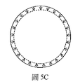
圖5係本發明實施例之各種變位模態的示意圖。 Fig. 5 is a schematic diagram of various displacement modes of the embodiment of the present invention.
圖6係本發明之變位偵測系統的一實施例之方塊圖。 Fig. 6 is a block diagram of an embodiment of the displacement detection system of the present invention.
圖7係本發明之變位偵測系統的另一實施例之方塊圖。 FIG. 7 is a block diagram of another embodiment of the displacement detection system of the present invention.
為充分瞭解本發明之目的、特徵及功效,茲藉由下述具體之實施例,並配合所附之圖式,對本發明做一詳細說明,說明如後: In order to fully understand the purpose, features and effects of the present invention, the following specific embodiments are used in conjunction with the accompanying drawings to give a detailed description of the present invention. The description is as follows:
請參考圖1,係本發明變位偵測方法之流程圖,其步驟包括步驟S10至步驟S60。步驟S10中,可提供不相同之第一斷面及第二斷面,於該第一斷面設置複數個第一偵測裝置,且於該第二斷面設置複數個第二偵測裝置,以該些第一偵測裝置及該些第二偵測裝置定義一多面體。特定而言,第一斷面及第二斷面可設定位於隧道中。另外,該些第一偵測裝置之數目為至少四個,該些第二偵測裝置之數目為至少四個,以定義該多面體至少為六面體。 Please refer to FIG. 1, which is a flowchart of the displacement detection method of the present invention. The steps include step S10 to step S60. In step S10, different first cross-sections and second cross-sections can be provided, a plurality of first detection devices are provided on the first cross-section, and a plurality of second detection devices are provided on the second cross-section, A polyhedron is defined by the first detection devices and the second detection devices. In particular, the first section and the second section can be set to be located in the tunnel. In addition, the number of the first detection devices is at least four, and the number of the second detection devices is at least four, so as to define the polyhedron to be at least a hexahedron.
詳細而言,如圖2A及圖2B,其為本發明實施例中隧道及斷面之示意圖,如圖2A所示,在隧道300中,先定義欲偵測之兩斷面,即第一斷面400a及第二斷面400b,在較佳實施例中,接著於第一斷面400a選擇D1~D4等4個偵測點位置,在第二斷面400b選擇D5~D8等4個偵測點位置,選擇上以使各偵測點盡可能涵蓋隧道300之內最多空間為佳。而在較佳實施例中,於偵測點位置D1~D4,設置第一偵測裝置110a~110d,於偵測點位置D5~D8,設置第二偵測裝置120a~120d,藉此定義如圖3A至圖3C之多面體200,且在較佳實施例中,多面體200可為六面體,更特定而言,多面體200可為長方體,惟於不同實施例中,偵測點位置及偵測裝置之數量不限於8個,且多面體不限於六面體或長方體,可利用不同數量之偵測點及偵測裝置,定義不同面數及形狀之多面體,並可組合不同之多面體,以更佳適應各種形狀之隧道。
In detail, as shown in Figure 2A and Figure 2B, which are schematic diagrams of the tunnel and cross section in the embodiment of the present invention, as shown in Figure 2A, in the
步驟S20中,可計算該多面體於第一時間之第一基準中心及於第二時間之第二基準中心。特定而言,該第一基準中心及該第二基準中心係該第一時間及該第二時間之該多面體的各投影面上之各平面基準中心。詳細而言,如圖3A至圖3C所示,其係多面體200及各投影面之示意圖。如圖3A所示,多面體200具體實施為六面體,且對應x軸方向之兩投影平面(或稱回歸平面,或簡稱平
面),分別定義為平面X1及平面X2。在圖3B中,對應y軸方向之兩平面,分別定義為平面Y1及平面Y2。在圖3C中,對應z軸方向之兩平面,分別定義為平面Z1及平面Z2。一般而言,x軸、y軸及z軸係設置為互相正交之座標軸。惟並不限於其他種類定義之座標軸,以適應不同隧道形狀之需求。
In step S20, the first reference center of the polyhedron at the first time and the second reference center at the second time can be calculated. Specifically, the first reference center and the second reference center are each plane reference center on each projection surface of the polyhedron at the first time and the second time. In detail, as shown in FIGS. 3A to 3C, which are schematic diagrams of the
步驟S30中,可基於該第一基準中心及該第二基準中心,計算平移值及旋轉值。接著於步驟S40中,可基於該平移值及該旋轉值,計算變形值。詳細而言,如圖4A至圖4C所示,其係本發明實施例之多面體平移及旋轉之示意圖。如圖4A所示,在第一時間下,多面體200之基準中心為C1。如圖4B所示,在第二時間下,多面體200若有變位,包含平移、旋轉或變形,及以上之組合,則其基準中心可能改變至C2。如圖4C所示,可計算第一基準中心C1及第二基準中心C2間之平移值及旋轉值。計算上可將第一基準中心C1及第二基準中心C2重合以利計算旋轉值。進一步可根據平移值及旋轉值,而計算出變形值。此中偵測資料所獲得的所有變位值,包含平移值、旋轉值及變形值,故可利用變位值(之物理量)扣除平移值及旋轉值,以獲得變形值。在較佳實施例中,所指基準中心,係指多面體200之三維形心,惟並不限於其他定義之基準中心,譬如質心、重心、內心、外心、垂心、旁心或其他不同定義之基準中心。且由多面體200之三維資料,可獲得三維之變位值,以及三維之平移值、旋轉值及變形值。
In step S30, a translation value and a rotation value can be calculated based on the first reference center and the second reference center. Then in step S40, a deformation value can be calculated based on the translation value and the rotation value. In detail, as shown in FIGS. 4A to 4C, which are schematic diagrams of the translation and rotation of the polyhedron according to the embodiment of the present invention. As shown in FIG. 4A, at the first time, the reference center of the
接著請參考圖2C,其例示另一種計算方式,為減化計算之資料量及複雜度,除了前述直接計算三維資料,亦可利用二維基準中心資料加以組合。如圖2C所例示,係以投影平面Z1及平面Z2為例,可分別計算平面Z1之基準中心(譬如平面Z1之形心)ZC1及平面Z2之基準中心(譬如平面Z2之形心)ZC2。以相同方式,亦可計算平面X1、平面X2、平面Y1及平面Y2之各基準中心XC1、XC2、YC1及YC2(未圖示)。並藉此進一步計算各平面基準中心(譬如形心)之變位值,即其平移值、旋轉值及變形值等。由於二維形心所需資料量較小,計算上較有
效率。藉此,可以各平面形心資料計算,並組合以評估三維變形值。換言之,此中所指多面體之基準中心,係可包含多面體三維之基準中心(三維形心),亦或多面體各投影面之平面基準中心(平面形心)之組合。可計算多面體200之剛體運動或多面體200之各回歸平面之剛體運動。
Next, please refer to FIG. 2C, which illustrates another calculation method to reduce the amount of data and complexity of the calculation. In addition to the aforementioned direct calculation of the three-dimensional data, the two-dimensional datum center data can also be used for combination. As shown in FIG. 2C, taking the projection plane Z1 and the plane Z2 as examples, the reference center of the plane Z1 (such as the centroid of the plane Z1) ZC1 and the reference center of the plane Z2 (such as the centroid of the plane Z2) ZC2 can be calculated respectively. In the same way, the reference centers XC1, XC2, YC1, and YC2 (not shown) of the plane X1, the plane X2, the plane Y1, and the plane Y2 can also be calculated. And to further calculate the displacement value of each plane reference center (such as centroid), that is, its translation value, rotation value, and deformation value. Due to the small amount of data required for the two-dimensional centroid, it is more computationally
effectiveness. In this way, the centroid data of each plane can be calculated and combined to evaluate the three-dimensional deformation value. In other words, the reference center of the polyhedron referred to herein may include the three-dimensional reference center of the polyhedron (three-dimensional centroid), or a combination of the plane reference centers (planar centroid) of each projection surface of the polyhedron. The rigid body motion of the
若該變形值不為零,進行步驟S50,若該變形值不為零,該些第一偵測裝置及該些第二偵測裝置於該第二時間之位置進行第三時間及第四時間的斷面測量,該斷面測量包含該第一斷面及該第二斷面的數量足以偵測斷面變形之非固定監測點的三維坐標測量。特定而言,可於該些第一偵測裝置110a~110d及該些第二偵測裝置120a~120d所在第一斷面與第二斷面上,於第三時間以具有自動目標辨識功能之全站儀約略等距量測量測密度足以偵測該隧道變形之非固定監測點的三維座標,於第四時間利用該全站儀自動目標辨識功能自動放樣量測第三時間原非固定監測點的三維座標。第一時間、第二時間、第三時間及第四時間係依時間由前向後排序。
If the deformation value is not zero, proceed to step S50. If the deformation value is not zero, the first detection devices and the second detection devices perform the third time and the fourth time at the second time position The cross-section measurement includes the three-dimensional coordinate measurement of the non-fixed monitoring point where the number of the first cross-section and the second cross-section is sufficient to detect the deformation of the cross-section. Specifically, the first and second cross-sections where the
再者,進行步驟S60,可基於該非固定監測點於該第三時間及該第四時間的坐標差異得到變位值,且計算該變位值之變位模態組成,變位模態包含剛體運動變位模態與變形變位模態。詳細而言,可基於該非固定監測點於該第三時間及該第四時間的坐標差異得到斷面非固定監測點之變位值,用以計算變位模態組成。該變位模態之數目可為複數個,該變位模態包含剛體運動變位模態與變形變位模態兩類。剛體運動變位模態包含水平平移變位模態、垂直平移變位模態與旋轉變位模態等變位模態,變形變位模態包含斷面監測點相對於斷面形心放大或縮小之均勻變形模態,及相對於該斷面形心之變形為橢圓形變形模態,相對於該斷面形心之變形為三角形變形模態,相對於該斷面形心之變形為四邊形變形模態,相對於該斷面形心之變形為五邊形變形模態,乃至相對於該斷面形心之變形為多邊形變形模態之複數種變位模態。 Furthermore, in step S60, the displacement value can be obtained based on the coordinate difference between the non-fixed monitoring point at the third time and the fourth time, and the displacement modal composition of the displacement value is calculated. The displacement mode includes a rigid body Movement displacement mode and deformation displacement mode. In detail, based on the coordinate difference of the non-fixed monitoring point at the third time and the fourth time, the displacement value of the non-fixed monitoring point of the section can be obtained to calculate the displacement modal composition. The number of the displacement modes can be plural, and the displacement modes include rigid body motion displacement modes and deformation displacement modes. The rigid body movement displacement modes include horizontal translation displacement modes, vertical translation displacement modes, and rotation displacement modes. The deformation displacement modes include the magnification or enlargement of the cross-section monitoring point relative to the cross-section centroid. The reduced uniform deformation mode, and the deformation relative to the cross-section centroid is an elliptical deformation mode, the deformation relative to the cross-section centroid is a triangular deformation mode, and the deformation relative to the cross-section centroid is a quadrilateral The deformation mode is a pentagonal deformation mode with respect to the centroid of the cross section, and even a plurality of deformation modes in which the deformation with respect to the centroid of the cross section is a polygonal deformation mode.
此外,本發明可基於該變形值以決定是否計算該多面體之絕對座標。本發明之一實例中的該些第一偵測裝置110a~110d及該些第二偵測裝置120a~120d更包含全球定位系統之一部分單元以控制測量、導線控制測量、路線回歸或其組合,且偵測絕對座標。
In addition, the present invention can determine whether to calculate the absolute coordinates of the polyhedron based on the deformation value. The
詳細而言,當多面體200有顯著變形時,隧道變位偵測與模態解析系統100除可改以絕對座標監測外,為偵測隧道複雜多樣之變位,進一步啟動斷面測量。斷面測量以預先設置偵測裝置為定位基準,針對第一斷面400a及第二斷面400b進行量測,每個斷面量測點可不小於32點。在第三時間下第一斷面與第二斷面獲得量測值,與第四時間第一斷面與第二斷面之量測值,可計算第一斷面與第二斷面之斷面變位值。藉此單一斷面超過32點之變位值,可精確描述隧道變位的量值和發生位置,以反映實際隧道行為。
In detail, when the
在較佳實施例中,為兼顧偵測之準確性及效率,可於平時僅偵測多面體之三維相對座標,而不偵測絕對座標。僅當相對座標之計算結果判定多面體200已有明顯變形時,始進一步利用第一偵測裝置110a~d及第二偵測裝置120a~d之全球定位系統(Global Positioning System,GPS)控制測量、導線控制測量、路線回歸或以上之組合等,以取得多面體200之三維絕對座標,以獲得更精確之計算結果。藉此,若相對座標評估無明顯變形時,本發明可持續以相對座標偵測,以得較高效率及較低成本。
In a preferred embodiment, in order to take into account the accuracy and efficiency of detection, only the three-dimensional relative coordinates of the polyhedron can be detected at ordinary times, and the absolute coordinates are not detected. Only when the calculation result of the relative coordinates determines that the
圖5為本發明實施例之變位模態的示意圖。隧道斷面變位分解為旋轉模態(圖500A)、垂直平移模態(圖500B)、均勻變形模態(圖500C)、橢圓變形模態(圖500D)、三角變形模態(圖500E)、四邊變形模態(圖500F)及其他模態之組合,各模態對應分量可為零,如該隧道斷面變位模態可能僅包含垂直平移、均勻變形、橢圓變形、三角變形、四邊變形及其他模態,但不含任何旋轉量。此中所指之變位模態,係可包含相互獨立之斷面剛體運動變位模態,其計有垂 直平移變位模態、水平平移變位模態及旋轉變位模態,以及相互獨立之斷面變形型態,包含但不限於均勻變形模態、橢圓變形模態、三角變形模態、四邊變形模態、多邊變形模態等。藉此,複雜不易解析之隧道變位可化為相互獨立的各變位模態及/或變形模態之組合。 Fig. 5 is a schematic diagram of a displacement mode of an embodiment of the present invention. The deformation of the tunnel section is decomposed into rotation mode (Figure 500A), vertical translation mode (Figure 500B), uniform deformation mode (Figure 500C), elliptical deformation mode (Figure 500D), and triangular deformation mode (Figure 500E) , Four-sided deformation mode (Figure 500F) and the combination of other modes, the corresponding component of each mode can be zero, for example, the tunnel section deformation mode may only include vertical translation, uniform deformation, elliptical deformation, triangular deformation, four sides Deformation and other modes, but without any rotation. The displacement modes referred to here can include independent cross-section rigid body motion displacement modes, which include vertical Straight translational displacement mode, horizontal translational displacement mode and rotation displacement mode, as well as mutually independent cross-sectional deformation modes, including but not limited to uniform deformation mode, elliptical deformation mode, triangular deformation mode, four sides Deformation mode, polygonal deformation mode, etc. In this way, the complex and difficult-to-analyze tunnel displacements can be transformed into mutually independent displacement modes and/or combinations of deformation modes.
在一些實施例中,第一偵測裝置110a~110d及第二偵測裝置120a~120d可包含位移偵測器。在不同實施例中,亦可包含溫度、應力、轉角、應變、速度、加速度、壓力、磁場或以上之組合之偵測器。在其他實施例中,亦可包含GPS控制測量、導線控制測量、路線回歸等偵測技術。
In some embodiments, the first detecting
請參考圖6及圖7,其係本發明之變位偵測系統的兩種實施例之方塊圖,其包括複數個第一偵測裝置110a~110d、複數個第二偵測裝置120a~120d、以及處理裝置130或處理單元1101。處理裝置130或處理單元1101可為電路、晶片、中央處理器、微處理器(MCU)或其組合。
Please refer to FIGS. 6 and 7, which are block diagrams of two embodiments of the displacement detection system of the present invention, which include a plurality of
如上所述之第一偵測裝置110a~110d可設置於第一斷面400a,且第二偵測裝置120a~120d可設置於第二斷面400b,第一偵測裝置110a~110d及第二偵測裝置120a~120d可定義一多面體200。進一步而言,第一偵測裝置110a~110d之數目為至少四個,第二偵測裝置120a~120d之數目為至少四個,以定義多面體200至少為六面體。
As mentioned above, the
如上所述之處理裝置130或處理單元1101,其中,處理裝置130可與第一偵測裝置110a~110d及第二偵測裝置120a~120d耦接,或者處理單元1101可至少設置於第一偵測裝置110a~110d及第二偵測裝置120a~120d之其中之一,且其他之第一偵測裝置及第二偵測裝置至少與處理單元1101耦接,其中,處理裝置130或處理單元1101計算多面體200於第一時間之第一基準中心C1及於第二時間之第二基準中心C2,且基於第一基準中心C1及第二基準中心C2計算平移值及旋轉值,另基於該平移值及該旋轉值計算變形值,並於該變形
值不為零時,令第一偵測裝置110a~110d及第二偵測裝置120a~120d於該第二時間之位置進行第三時間及第四時間的斷面測量以計算斷面的變位值。
The
另外,本發明之變位偵測系統可更包含儲存裝置或儲存單元,儲存裝置可與處理裝置130、處理單元1101、第一偵測裝置110a~110d、第二偵測裝置120a~120d或其組合耦接,儲存單元可可至少設置於第一偵測裝置110a~110d及第二偵測裝置120a~120d之其中之一,且其他之第一偵測裝置及第二偵測裝置可與儲存單元耦接,而處理裝置130或處理單元1101可與儲存單元耦接,以儲存偵測所得資料及/或計算資料。儲存裝置或儲存單元可為例如燒錄式光碟機、硬碟機、軟碟機、通用串行總線(USB)、動態隨機存取記憶體、快閃記憶體、電子抹除式可複寫唯讀記憶體(EEPROM)、可擦除可規劃式唯讀記憶體(EPROM)等。
In addition, the displacement detection system of the present invention may further include a storage device or a storage unit. The storage device may be combined with the
如上所述之處理裝置130或處理單元1101可基於該變位值計算變位模態,且若該變位模態之數目為複數個,該些變位模態包含水平平移變位模態、垂直平移變位模態、旋轉變位模態、均勻變形模態。
The
如上所述之第一基準中心C1及第二基準中心C2可為該第一時間及該第二時間之多面體200的各投影面上之各平面基準中心ZC1,ZC2。另外,第一斷面400a及第二斷面400b可以第一偵測裝置110a~110d及第二偵測裝置120a~120d為基準,以對第一斷面400a及第二斷面400b進行多點斷面測量,各斷面至少包含32個量測點,用以偵測該斷面的變位。
The first reference center C1 and the second reference center C2 as described above may be the plane reference centers ZC1, ZC2 on each projection surface of the
本發明之處理裝置130或處理單元1101可基於該變形值以決定是否計算多面體200之絕對座標。本發明之第一偵測裝置110a~110d及第二偵測裝置120a~120d可更包含全球定位系統之一部分單元以控制測量、導線控制測量、路線回歸或其組合,且偵測絕對座標。本發明之變位偵測系統的其它詳細內容已於上文敘述,不再贅述。
The
值得注意的是,該耦接可為電性耦接及/或光學耦接等可傳遞訊號或指令的耦接方式。 It should be noted that the coupling may be a coupling method capable of transmitting signals or commands, such as electrical coupling and/or optical coupling.
綜上所述,本發明能發展一種將固定監測點與非固定監測點分開考慮,且可獲得三維變形之解析方法。其不僅能提供隧道監測斷面之平移、旋轉與變形,也可解算隧道區間之平移、旋轉與變形,將原本以二維平面為單位之概念推廣至三維。進而提供隧道區段之三維平移量、旋轉量與變形量,及用於界定隧道區段、設有固定監測點之變形監測斷面,其不僅能有效利用固定監測點位置確定、確實反映隧道區域行為之優勢,並可將區段內相對剛體運動與襯砌裂縫紀錄和其他監測結果比較,協助評估隧道健全度與安全性,研判引致隧道襯砌異狀之肇因。 In summary, the present invention can develop an analytical method that separates fixed monitoring points from non-fixed monitoring points and obtains three-dimensional deformation. It can not only provide the translation, rotation and deformation of the tunnel monitoring section, but also calculate the translation, rotation and deformation of the tunnel section, and extend the original concept of using a two-dimensional plane as a unit to three-dimensional. Furthermore, it provides the three-dimensional translation, rotation, and deformation of the tunnel section, and the deformation monitoring section used to define the tunnel section with fixed monitoring points. It can not only effectively use the fixed monitoring point to determine the location, but also reflect the tunnel area. It can also compare the relative rigid body movement in the section with the records of lining cracks and other monitoring results to assist in evaluating the soundness and safety of the tunnel, and to determine the cause of the abnormal shape of the tunnel lining.
本發明在上文中已以較佳實施例揭露,然熟習本項技術者應理解的是,該實施例僅用於描繪本發明,而不應解讀為限制本發明之範圍。應注意的是,舉凡與該實施例等效之變化與置換,均應設為涵蓋於本發明之範疇內。因此,本發明之保護範圍當以申請專利範圍所界定者為準。 The present invention has been disclosed in a preferred embodiment above, but those skilled in the art should understand that the embodiment is only used to describe the present invention and should not be construed as limiting the scope of the present invention. It should be noted that all changes and substitutions equivalent to this embodiment should be included in the scope of the present invention. Therefore, the protection scope of the present invention should be defined by the scope of the patent application.
S10、S20、S30、S40、S50、S60:步驟 S10, S20, S30, S40, S50, S60: steps
Claims (16)
Priority Applications (1)
| Application Number | Priority Date | Filing Date | Title |
|---|---|---|---|
| TW107118689A TWI709939B (en) | 2018-05-31 | 2018-05-31 | Displacement detection method and system |
Applications Claiming Priority (1)
| Application Number | Priority Date | Filing Date | Title |
|---|---|---|---|
| TW107118689A TWI709939B (en) | 2018-05-31 | 2018-05-31 | Displacement detection method and system |
Publications (2)
| Publication Number | Publication Date |
|---|---|
| TW202004646A TW202004646A (en) | 2020-01-16 |
| TWI709939B true TWI709939B (en) | 2020-11-11 |
Family
ID=69942201
Family Applications (1)
| Application Number | Title | Priority Date | Filing Date |
|---|---|---|---|
| TW107118689A TWI709939B (en) | 2018-05-31 | 2018-05-31 | Displacement detection method and system |
Country Status (1)
| Country | Link |
|---|---|
| TW (1) | TWI709939B (en) |
Citations (4)
| Publication number | Priority date | Publication date | Assignee | Title |
|---|---|---|---|---|
| CN101882171A (en) * | 2010-05-21 | 2010-11-10 | 中交第二公路勘察设计研究院有限公司 | Method for fast establishing interactive tunnel and wall rock body three-dimensional models |
| CN107014683A (en) * | 2017-04-12 | 2017-08-04 | 山东东山王楼煤矿有限公司 | A kind of acquisition methods of earth's surface Rock Displacement Movement parameter |
| TWI612277B (en) * | 2017-01-20 | 2018-01-21 | Chuan Hai Yueh | Tunnel displacement monitoring method |
| US20180038683A1 (en) * | 2015-12-25 | 2018-02-08 | Tongji University | System for quickly detecting tunnel deformation |
-
2018
- 2018-05-31 TW TW107118689A patent/TWI709939B/en active
Patent Citations (4)
| Publication number | Priority date | Publication date | Assignee | Title |
|---|---|---|---|---|
| CN101882171A (en) * | 2010-05-21 | 2010-11-10 | 中交第二公路勘察设计研究院有限公司 | Method for fast establishing interactive tunnel and wall rock body three-dimensional models |
| US20180038683A1 (en) * | 2015-12-25 | 2018-02-08 | Tongji University | System for quickly detecting tunnel deformation |
| TWI612277B (en) * | 2017-01-20 | 2018-01-21 | Chuan Hai Yueh | Tunnel displacement monitoring method |
| CN107014683A (en) * | 2017-04-12 | 2017-08-04 | 山东东山王楼煤矿有限公司 | A kind of acquisition methods of earth's surface Rock Displacement Movement parameter |
Also Published As
| Publication number | Publication date |
|---|---|
| TW202004646A (en) | 2020-01-16 |
Similar Documents
| Publication | Publication Date | Title |
|---|---|---|
| JP6873437B2 (en) | An analysis method for determining the stress change of the tunnel lining through the amount of displacement, and its equipment and system | |
| JP6083091B2 (en) | Reinforcing bar inspection support device and program | |
| CN110398231A (en) | Acquisition methods, device, computer equipment and the storage medium of metope parameter | |
| CN105550448A (en) | Pre-drilling three-dimensional borehole modeling method and device based on drilling track design parameters | |
| CN109583116B (en) | Dynamic inversion method of initial stress field in underground engineering based on multi-source measured information | |
| KR102235632B1 (en) | Machine vision system | |
| CN104567773B (en) | The sloped correcting method of the base portion of arm type three-dimensional measuring machine and the support measuring machine | |
| TW201344633A (en) | System and method for measuring curved surfaces of objects | |
| CN114459656B (en) | Three-dimensional identification method and device for disturbance stress evolution process of underground cavern surrounding rock | |
| JP6990476B1 (en) | Welding inspection method, welding inspection system, welding inspection program | |
| JP7244336B2 (en) | Mountain tunnel concrete thickness measuring method and measuring device | |
| US20190158811A1 (en) | Stereo camera and stereophotogrammetric method | |
| JP2013072705A (en) | Detection method of discontinuity surface on rock bed slope and detection device of the same | |
| TWI709939B (en) | Displacement detection method and system | |
| CN111336985B (en) | Monitoring method and device for goaf iron tower, storage medium and electronic equipment | |
| US11117228B2 (en) | Manufacturing method and manufacturing apparatus | |
| KR100994742B1 (en) | The method of collision detection and passpoint generation for moving path in 3 dimensional coordinate measuring machine | |
| JP7602688B1 (en) | Reinforcing bar weld bead detection method and device | |
| CN113048972B (en) | Method and system for determining attitude and position of mining engineering machinery | |
| Jones et al. | A method for determining field accuracy of mobile scanning devices for geomechanics applications | |
| JP6773280B2 (en) | Tunnel excavation management method and management equipment | |
| CN108050986B (en) | Method for Determining the Position of the Internal Fracture Surface of Rock and Soil Mass Based on Multi-point Displacement Meter Monitoring | |
| KR20120009185A (en) | Multi-directional ground displacement measurement method | |
| TWI612277B (en) | Tunnel displacement monitoring method | |
| CN109190587B (en) | Method and system for evaluating lane line data accuracy and recall rate |