[go: up one dir, main page]

TWI692412B - Method of printing and apparatus for the same - Google Patents

Method of printing and apparatus for the same Download PDF

Info

Publication number
TWI692412B
TWI692412B TW105133941A TW105133941A TWI692412B TW I692412 B TWI692412 B TW I692412B TW 105133941 A TW105133941 A TW 105133941A TW 105133941 A TW105133941 A TW 105133941A TW I692412 B TWI692412 B TW I692412B
Authority
TW
Taiwan
Prior art keywords
printing
head assembly
print head
curing device
separation distance
Prior art date
Application number
TW105133941A
Other languages
Chinese (zh)
Other versions
TW201718276A (en
Inventor
塔德 W 米勒
Original Assignee
荷蘭商耐克創新有限合夥公司
Priority date (The priority date is an assumption and is not a legal conclusion. Google has not performed a legal analysis and makes no representation as to the accuracy of the date listed.)
Filing date
Publication date
Application filed by 荷蘭商耐克創新有限合夥公司 filed Critical 荷蘭商耐克創新有限合夥公司
Publication of TW201718276A publication Critical patent/TW201718276A/en
Application granted granted Critical
Publication of TWI692412B publication Critical patent/TWI692412B/en

Links

Images

Landscapes

  • Ink Jet (AREA)

Abstract

A method and apparatus of providing varying gloss levels for a printed surface of a two-dimensional or three-dimensional printed structure is disclosed. The method includes dynamically adjusting the spacing between a printhead assembly and a curing device according to a target gloss level for the resulting printed structure.

Description

列印方法及其裝置 Printing method and device

本實施例大體上係關於列印,包含三維列印系統及方法。 This embodiment is generally related to printing, including a three-dimensional printing system and method.

列印系統可用於列印2D結構或油墨層以及由各種類型之3D列印材料形成之3D結構。三維列印系統及方法可與各種技術相關聯,該等技術包含熔融沈積成形(FDM;Fused Deposition Modeling)、電子束無模製造(EBF;Electron Beam Freeform Fabrication)、選擇性雷射燒結(SLS;Selective Laser Sintering)以及其他類型之三維列印技術。 The printing system can be used to print 2D structures or ink layers and 3D structures formed from various types of 3D printing materials. The three-dimensional printing system and method can be associated with various technologies, including fused deposition modeling (FDM; Fused Deposition Modeling), electron beam moldless manufacturing (EBF; Electron Beam Freeform Fabrication), and selective laser sintering (SLS; Selective Laser Sintering) and other types of 3D printing technology.

由三維列印系統形成之結構可與藉由其他製造技術形成之物體一起使用。此等包含在各種鞋類物件及/或服裝物件中使用之紡織物材料。 The structure formed by the three-dimensional printing system can be used with objects formed by other manufacturing techniques. These include textile materials used in various footwear and/or clothing items.

當依2D及/或3D列印時,一經列印元件之所得外表面(即,一油墨層之表面或一3D列印結構之一表面)可具有各種類型之光潔度。一個可能類型之光潔度係一光澤度,其之範圍可係(例如)自無光澤至高光澤。 When printing in 2D and/or 3D, the resulting outer surface of a printed element (ie, the surface of an ink layer or the surface of a 3D printing structure) can have various types of finishes. One possible type of finish is gloss, and its range can be, for example, from matt to high gloss.

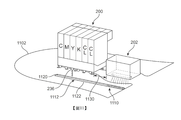
實施例包含用於在各種區域中以目標(即,預定)光澤度列印且固化一2D或3D結構之方法及一裝置。可藉由改變一列印系統之一列印頭總成與一固化器件之間之分離距離而變動結構之各種區域之光澤度。沿著一列印器件之軌或軌道移動列印頭總成及固化器件。可藉由增加列印頭總成與固化器件之間之分離距離而增加所達成之類型之光澤度(即,自無光澤移動至較光澤)。一些系統包含佈建,使得列印頭總成及固化器件經分開控制(即,致動),且因此其等沿著一軌或軌道之相對間隔可經自動動態調整而不需要在列印工作期間或之間之手動改變。 一般技術者在檢查以下圖及詳細描述之後將或將變得瞭解實施例之其他系統、方法、特徵及優點。全部此等額外系統、方法、特徵及優點旨在包含於此描述中,在實施例之範疇內且由以下申請專利範圍保護。 圖1係亦簡稱為列印系統100之三維列印系統100之一實施例之一示意圖。列印系統之一些實施例可包含在列印系統之不同器件當中分佈一或多個功能之佈建。如展示,列印系統100可包含列印器件102、計算系統104及網路106。在其他實施例中,列印系統可係一單一器件或組件(未展示)。 如本文中使用,術語「列印機」、「繪圖儀」、「三維列印機」或「三維列印系統」可指代可將多個層列印至一基板、一織物、一鞋類物件、一服裝物件或其他物件上之任何類型之系統。在一項實施例中,列印器件102可係一符號及圖形列印機。 Embodiments include a method and a device for printing and curing a 2D or 3D structure with target (ie, predetermined) gloss in various areas. The glossiness of various areas of the structure can be changed by changing the separation distance between a print head assembly of a printing system and a cured device. Move the print head assembly and curing device along the rail or track of a printing device. The type of gloss achieved (i.e., moving from matt to glossier) can be increased by increasing the separation distance between the print head assembly and the cured device. Some systems include deployments that allow the print head assembly and curing device to be controlled separately (ie, actuated), and therefore their relative spacing along a rail or track can be automatically dynamically adjusted without the need for printing work Manual changes during or between periods. One of ordinary skill will or will become aware of other systems, methods, features, and advantages of the embodiments after examining the following figures and detailed description. All such additional systems, methods, features, and advantages are intended to be included in this description, are within the scope of the embodiments, and are protected by the following patent applications. FIG. 1 is a schematic diagram of an embodiment of a three-dimensional printing system 100 also referred to as a printing system 100 for short. Some embodiments of the printing system may include the deployment of one or more functions distributed among different devices of the printing system. As shown, the printing system 100 may include a printing device 102, a computing system 104, and a network 106. In other embodiments, the printing system may be a single device or component (not shown). As used herein, the terms "printer," "plotter," "3D printer," or "3D printing system" may refer to printing multiple layers onto a substrate, fabric, or footwear Any type of system on an object, a clothing object, or other objects. In one embodiment, the printing device 102 may be a symbol and graphic printer.

列印系統100可利用各種類型之列印技術。技術可包含(但不限於)基於碳粉之列印、液體噴墨列印、固體油墨列印、染料昇華列印、無油墨列印(包含熱列印及UV列印)、微機電系統(MEMS;MicroElectroMechanical Systems)噴射列印技術以及任何其他列印方法。 The printing system 100 can utilize various types of printing technologies. Technology may include (but not limited to) toner-based printing, liquid inkjet printing, solid ink printing, dye sublimation printing, inkless printing (including thermal printing and UV printing), micro-electromechanical systems ( MEMS; MicroElectro Mechanical Systems) jet printing technology and any other printing methods.

一些實施例可使用積層製造技術或三維列印技術。三維列印或「3D列印」包括可用於藉由將連續材料層沈積於彼此之頂部上而形成三維物體之各種技術。可使用之例示性3D列印技術包含(但不限於)熔融細絲製造(FFF;Fused Filament Fabrication)、電子束無模製造(EBF;Electron Beam Freeform Fabrication)、直接金屬雷射燒結(DMLS;Direct Metal Laser Sintering)、電子束熔化(EMB;Electron Beam Melting)、選擇性雷射熔化(SLM;Selective Laser Melting)、選擇性熱燒結(SHS;Selective Heat Sintering)、選擇性雷射燒結(SLS;Selective Laser Sintering)、基於石膏之3D列印(PP;Plaster-Based 3D Printing)、分層物體製造(LOM;Laminated Object Manufacturing)、立體微影(SLA;Stereolithography)、數位光處理(DLP;Digital Light Processing)以及此項技術中已知之各種其他類型之3D列印或積層製造技術。自三維列印系統形成之結構可與藉由其他製造技術形成之物體一起使用。此等包含在各種鞋類物件、服裝物件及/或保護性物件中使用之紡織物材料。 Some embodiments may use layered manufacturing technology or three-dimensional printing technology. Three-dimensional printing or "3D printing" includes various techniques that can be used to form three-dimensional objects by depositing successive layers of materials on top of each other. Exemplary 3D printing techniques that can be used include (but are not limited to) Filament Fabrication (FFF; Fused Filament Fabrication), Electron Beam Freeform Fabrication (EBF; Electron Beam Freeform Fabrication), Direct Metal Laser Sintering (DMLS; Direct Metal Laser Sintering), electron beam melting (EMB; Electron Beam Melting), selective laser melting (SLM; Selective Laser Melting), selective thermal sintering (SHS; Selective Heat Sintering), selective laser sintering (SLS; Selective Laser Sintering), plaster-based 3D printing (PP; Plaster-Based 3D Printing), layered object manufacturing (LOM; Laminated Object Manufacturing), stereolithography (SLA; Stereolithography), digital light processing (DLP; Digital Light Processing ) And various other types of 3D printing or build-up manufacturing techniques known in the art. Structures formed from three-dimensional printing systems can be used with objects formed by other manufacturing techniques. These include textile materials used in various footwear, clothing and/or protective objects.

一些例示性實施例描繪將三維結構列印至一物件(例如,鞋類之一鞋面)上,然而,其他實施例可利用本文中論述之原理以列印及固化列印材料以用於任何應用。在一些其他實施例中,舉例而言,本文中論述之原理可用於列印及固化列印材料之薄膜或層,諸如可用於將一圖形或標記列印至一基板上。如在此實施方式中及在申請專利範圍中使用,術語「可列印特徵」指代藉由列印(例如,自一噴嘴噴出)形成之任何層、部分或結構。在一些情況中,一可列印特徵可係如可由一習知噴墨列印機沈積之一或多個油墨層。在其他情況中,一可列印特徵可係已使用一結構列印材料(諸如熱塑性材料)列印至一基板上之一3D結構特徵。 在一些情況中,列印系統100可利用兩個或兩個以上不同列印技術之一組合。舉例而言,在一些實施例中,可將彩色油墨列印為薄層而可列印清透或不透明列印材料以形成一經列印物體或形式之結構層。所使用之列印技術之類型可根據包含(但不限於)以下之因素變動:目標物件之材料、目標物件之大小及/或幾何形狀、經列印影像之所要性質(諸如持久性、色彩、油墨密度等)以及列印速度、列印成本及維護需要。 積層製造程序可用於在平坦接收表面上以及在輪廓化或非平坦表面上形成結構。舉例而言,在圖中描繪之一些實施例可繪示方法,藉此將材料列印至一物件之一平坦表面(諸如具有一平坦或未組裝組態之一鞋面之一材料區段)上。在此等情況中,可藉由將材料沈積為亦係平坦之薄膜而將材料列印至表面上。因此,一列印頭或噴嘴可在一或多個水平方向上移動以施覆一第N材料層且接著在垂直方向上移動以開始形成N+1層。然而,應理解,在其他實施例中,可將材料列印至一輪廓化或非平坦表面上。舉例而言,可將材料列印至一三維鞋楦上,其中鞋楦之表面非平坦。在此等情況中,施覆至表面之經列印層亦可係輪廓化。為了完成此列印方法,一列印頭或噴嘴可經結構設計以沿著一輪廓化表面移動且傾斜、旋轉或另外移動使得列印頭或噴嘴始終近似法向於其中施覆經列印材料之表面對準。在一些情況中,可將一列印頭安裝至一機器人臂,諸如具有6自由度之一鉸接式機器人臂。替代地,在又其他實施例中,可在一噴嘴下方重新定向具有一輪廓化表面之一物體使得可將經列印材料之輪廓化層施覆至物體。舉例而言,實施例可利用在於2013年1月17日公開之Mozeika等人之標題為「Robotic fabricator」之美國專利公開案第2013/0015596號(且在2012年6月22日申請為美國申請案第13/530,664號)中揭示之任何系統、特徵、組件及/或方法,該案之全文以引用的方式併入本文中。實施例亦可利用在在於2012年2月28日頒布之Cannell等人之標題為「Computerized apparatus and method for applying graphics to surfaces」之美國專利第8,123,350號中揭示之任何系統、特徵、組件及/或方法,該案之全文以引用的方式併入本文中。因此,可瞭解,本實施例不限於用於列印至平坦表面之列印程序且可結合可列印至具有任何類型之幾何形狀之任何類型之表面之列印系統使用。 一般言之,實施例可將任何類型之列印材料施覆至一基板。如本文中使用,術語「列印材料」或「可列印材料」指代可在一積層製造程序期間列印、噴出、發射或另外沈積之任何材料。例示性列印材料包含油墨以及樹脂、塑膠或與2D及/或3D列印相關聯之其他列印材料。在一些實施例中,列印技術中使用之材料可係任何水性油墨、基於染料之油墨、基於顏料之油墨、基於溶劑之油墨、染料昇華油墨、熱塑性材料(例如,PLA及ABS)及熱塑性粉末、丙烯酸樹脂、聚胺基甲酸酯、熱塑性聚胺基甲酸酯、聚矽氧或任何其他可固化物質。材料之又進一步實例包含高密度聚氨酯、共晶金屬、橡膠、油土、橡皮泥、RTV聚矽氧、瓷、金屬黏土、陶瓷材料、石膏及光聚合物以及已知用於3D列印之可能其他材料。 在一些實施例中,一列印材料可係在高於一預定溫度(諸如一玻璃轉變溫度及/或一熔化溫度)下實質上可模製及/或柔軟之任何材料。在一項實施例中,一列印材料具有一或多個熱性質,諸如一玻璃-液體轉變(「玻璃轉變」)溫度及/或一熔化溫度。舉例而言,列印材料可係具有一玻璃轉變溫度及一熔化溫度之一熱塑性材料。如本文中使用,熱塑性材料可包含(例如)丙烯酸、尼龍、聚苯并咪唑、聚乙烯、聚丙烯、聚苯乙烯、聚氯乙烯、聚四氟乙烯(PTFE)及類似者。 在一些實施例中,一列印材料可UV固化。一般言之,可使用任何適當類型之可UV固化之列印材料,包含丙烯酸樹脂、聚胺基甲酸酯、TPU、聚矽氧或任何其他適當列印材料。 列印系統之一些實施例可包含允許將經列印結構直接列印至一或多個物件上之佈建。術語「物件」旨在包含鞋類物件(例如,鞋子)及服裝物件(例如,襯衫、褲子等)兩者。如貫穿本發明使用之術語「鞋類物件」及「鞋類」包含任何鞋類及與鞋類相關聯之任何材料(包含一鞋面)且亦可應用於各種運動鞋類類型,包含(例如)棒球鞋、籃球鞋、交叉訓練鞋、自行車運動鞋、橄欖球鞋、網球鞋、足球鞋及登山靴。如本文中使用,術語「鞋類物件」及「鞋類」亦包含通常視為非運動、正式或裝飾性之鞋類類型,包含禮鞋、平底便鞋、涼鞋、拖鞋、船鞋及工作靴。 雖然在鞋類物件之背景內容中描述所揭示之實施例,但各項實施例可進一步同等地應用於包含三維列印之任何衣服、服裝或設備物件。舉例而言,各項實施例可應用於禮帽、帽子、襯衫、針織衫、夾克、短襪、短褲、褲子、內衣、運動支援服裝、手套、腕/臂帶、袖套、髮帶、任何針織材料、任何編織材料、任何不織布材料、運動設備等。因此,如本文中使用,術語「服裝物件」可指代任何服裝或衣服,包含任何鞋類物件以及禮帽、帽子、襯衫、針織衫、夾克、短襪、短褲、褲子、內衣、運動支援服裝、手套、腕/臂帶、袖套、髮帶、任何針織材料、任何編織材料、任何不織布材料及類似者。 為了將經列印材料直接施覆至一或多個物件,列印器件102可能夠列印至各種類型之材料之表面上。具體言之,在一些情況中,列印器件102可能夠列印至各種材料(諸如一紡織物、天然織物、合成織物、針織物、編織材料、不織布材料、網狀織物、皮革、合成皮革、聚合物、橡膠及發泡體或其等之任何組合)之表面上而不需要插置於一基板與經列印材料之底部之間之一釋放層,且不需要在其上列印之一完美或接近完美的平坦基板表面。舉例而言,所揭示方法可包含將一樹脂、丙烯酸、熱塑性材料或油墨材料列印至一織物(例如,一針織材料)上,其中將材料黏著/結合至織物,且其中材料在經折曲、輥壓、加工或經受額外組裝程序/步驟時通常不分層。如貫穿本發明使用,術語「織物」可用於大致指代選自任何紡織物、天然織物、合成織物、針織物、編織材料、不織布材料、網狀織物、皮革、合成皮革、聚合物、橡膠及發泡體之材料。 在一些實施例中,列印系統100可包含控制及/或接收來自列印器件102之資訊之佈建。此等佈建可包含計算系統104及網路106。一般言之,術語「計算系統」指代一單一電腦之計算資源、一單一電腦之計算資源之一部分及/或彼此通信之兩個或兩個以上電腦。任何此等資源可由一或多個人類使用者操作。在一些實施例中,計算系統104可包含一或多個伺服器。在一些實施例中,一列印伺服器可主要負責控制列印器件102及/或與列印器件102通信,而一單獨電腦(例如,桌上型電腦、膝上型電腦或平板電腦)可促成與一使用者之互動。計算系統104亦可包含一或多個儲存器件,包含(但不限於)磁性器件、光學器件、磁光學器件及/或記憶體(包含揮發性記憶體及非揮發性記憶體)。 在其中使用一計算系統之該等例項中,可使用任何適合硬體或硬體系統以促成控制及/或接收來自列印器件102之資訊之佈建。在一些實施例中,在使用一計算系統之情況下,計算系統104可包含中央處理器件115、觀看介面116 (例如,一監測器或螢幕)、輸入器件117 (例如,鍵盤及滑鼠)及用於設計一經列印結構之一電腦輔助設計表示之軟體。然而,在其他實施例中,可使用其他形式之硬體系統。 在其中使用用於設計一經列印結構之一電腦輔助設計表示之軟體之該等例項中,可使用任何適合資訊以促成用於設計一經列印結構之一電腦輔助設計表示之佈建。在至少一些實施例中,一經列印層及/或經列印結構之電腦輔助設計表示可不僅包含關於結構之幾何形狀之資訊而且包含關於列印結構之各種部分所需之材料之資訊。然而,在其他實施例中,可使用不同資訊。 在其中使用用於設計一經列印結構之一電腦輔助設計表示之軟體之該等例項中,可使用任何適合設計結構以將設計轉換為可由列印器件102 (或與列印器件102通信之一相關列印伺服器)解譯之資訊。在一些實施例中,可如下操作列印系統100以提供已使用一三維列印或積層程序形成之一或多個結構。可使用計算系統104以設計一結構。此可使用某個類型之CAD軟體或其他類型之軟體完成。接著可將設計轉換為可由列印器件102 (或與列印器件102通信之一相關列印伺服器)解譯之資訊。在一些實施例中,可將設計轉換為一三維可列印檔案,諸如一立體微影檔案(STL檔案),在其他情況中,可將設計轉換為一不同設計結構。在又其他實施例中,關於一待列印結構之資訊可以一影像檔案之形式發送,在該情況中可使用不同區域之影像資訊(色彩、色調、色澤、透明度等)以判定一對應3D結構。 在其中使用一網路之該等例項中,網路106可使用促成計算系統104與列印器件102之間之資訊之交換之任何有線或無線佈建。在一些實施例中,網路106可進一步包含各種組件,諸如網路介面控制器、轉發器、集線器、橋接器、開關、路由器、數據機及防火墻。在一些實施例中,網路106可係促成列印系統100之兩個或兩個以上系統、器件及/或組件之間之無線通信之一無線網路。無線網路之實例包含(但不限於)無線個人區域網路(包含例如藍芽)、無線區域網路(包含利用IEEE 802.11 WLAN標準之網路)、無線網狀網路、行動器件網路以及其他類型之無線網路。在其他情況中,網路106可係一有線網路,包含其等之信號由雙絞線、同軸纜線及光纖促成之網路。在又其他情況中,可使用有線及無線網路及/或連接之一組合。 如所論述,一列印系統可跨一或多個器件或系統分佈各種功能性。在其中列印系統包含在列印系統100之不同器件當中分佈一或多個功能之佈建之該等例項中,可使用任何適合協定、格式及方法以促成列印系統100之器件當中之通信。在一些實施例中,此等通信係使用網路106進行,在其他情況中,此等通信可直接在列印系統100之器件之間進行。 圖2繪示列印器件102 (見圖1)之一些組件之一放大部分之一示意圖。具體言之,圖2展示一列印頭總成200以及固化器件202。在圖2之實施例中,列印頭總成200及固化器件202進一步安裝至致動系統204。在一些情況中,致動系統204可包含用於促成列印頭總成200及/或固化器件202之移動之各種佈建。在一項實施例中,致動系統204包含一或多個軌道206。可使用一或多個致動器件將列印頭總成200及固化器件202安裝至軌道206,該一或多個致動器件容許列印頭總成200及固化器件202附接至軌道206且沿著軌道206 (即,在與列印器件102之縱向軸線210對準之方向上)運送。 在至少一些實施例中,一列印器件可包含安置於一列印頭之相對側上之兩個分離固化器件。此一組態容許一固化器件尾隨一列印頭「之後」,而不管列印頭之運動方向(即,沿著軸線210向左或向右)如何。在圖1至圖2之實施例中,展示一第二固化器件(圖2中之固化器件219)。然而,為了圖解之目的,自剩餘圖省略固化器件219,此係因為此第二固化器件之操作可與固化器件202之操作相同。 為了清楚起見,在圖2中未展示控制列印頭總成200及固化器件202之運動之致動器件。然而,可理解,可使用用於將列印頭及/或固化燈移動至一列印機或類似器件內之各種位置之任何已知系統、器件或方法。此等佈建可包含各種類型之電動馬達或此項技術中已知之用於列印機中之其他驅動器件。 列印器件之一些實施例可包含允許彩色列印之佈建。在一些實施例中,列印系統可使用CMYK列印。在其他實施例中,彩色列印可使用另一適合列印方法進行。 在其中使用CMYK列印之該等例項中,可使用任何適合器件、協定、標準及方法以促成彩色列印。如本文中使用,「CMYK」可指代在彩色列印中使用之四個顏料:「C」針對一青色顏料,「M」針對一洋紅色顏料,「Y」針對一黃色顏料且「K」針對一黑色顏料。在Miller在2015年1月1日公開之標題為「Additive Color Printing」之美國專利公開案第2015-0002567號(在2013年6月26日申請之美國專利申請案第13/927,551號)中揭示使用CMYK列印之一列印器件之一實例,該申請案以引用的方式併入本文中且在下文中稱為「彩色列印」申請案。在一些實施例中,列印系統100可包含在彩色列印申請案中揭示之系統、組件、器件及方法之一或多個特徵以促成彩色列印。舉例而言,列印器件102可經結構設計以藉由將一列印材料之液滴(包含一或多個顏料)施配至一基底上而列印一影像。如本文中使用,液滴可指代任何適合體積之列印材料。舉例而言,一液滴可係一毫升之列印材料。在其他實施例中,列印系統100可使用其他系統、組件、器件及方法。 在其中使用CMYK列印之該等例項中,CMYK可藉由列印且互混顏料之各種組合而產生或近似於在可見光譜中之任何色彩。參考圖2及圖3,列印頭總成200包含青色(C)、洋紅色(M)及黃色(Y)之分離油墨匣。因此,列印頭總成可針對色彩青色(由噴嘴232施配)、洋紅色(由噴嘴234施配)及黃色(由噴嘴236施配)施配油墨或其他彩色列印材料。可互混經施配彩色材料之組合以產生紅色、綠色及藍色之一或多個色彩。可使用彩色列印材料之進一步互混以產生紅色、綠色、藍色、青色、洋紅色及黃色之外之許多更多色彩。在例示性實施例中,列印頭總成200可進一步包含用於施配可由噴嘴238施配之黑色油墨或黑色列印材料(K)之一分離匣。在一些實施例中,列印器件102可包含一白色匣(未展示)。雖然在圖2中描繪用於各列印材料之一個匣,但依據一些實施例,列印器件102可包含用於列印頭總成200之一或多個列印材料之一個以上匣。 在其中使用CMYK列印之該等例項中,可使用任何適合列印材料以促成彩色列印。在一些實施例中,CMYK列印材料可係水基的。在其他實施例中,CMYK列印材料可係油基的。在一些實施例中,CMYK列印材料可包含一結構列印材料。 一些實施例亦可使用一結構列印材料,其之目的係提供3D結構而非色彩。在一些實施例中,CMYK列印材料可包含一清透及/或透明結構列印材料。在一些實施例中,一CMYK列印材料可包含一不透明結構列印材料。在一些實施例中,CMYK列印材料可包含一半透明結構列印材料。在其他實施例中,結構材料可具有透明結構材料及/或半透明結構材料之一組合。 參考圖2及圖3,列印頭總成200包含施配由噴嘴240及噴嘴242施配之一清透結構列印材料(CL)之兩個匣。雖然例示性實施例可使用清透結構列印材料,但其他實施例可包含具有顏料之結構列印材料。 實施例可包含用於固化一或多個類型之列印材料之佈建。一般言之,可使用用於固化可列印物質之任何已知方法及/或器件。一些實施例可使用紫外線(UV)固化燈。如圖2及圖3中展示,列印系統100 (圖1中展示)包含固化器件202。在一些實施例中,固化器件202包含外殼220及UV發射源222 (例如,一燈泡)。如下文中進一步詳細論述,固化器件202可經結構設計以在最近經噴出列印材料(諸如油墨或結構列印材料)上方通過以完全或部分固化列印材料。 使用一UV燈之實施例可利用任何類型之UV燈。可與實施例一起使用之例示性燈包含(但不限於)水銀蒸氣燈(包含H型、D型或V型水銀燈)、螢光燈及/或UV LED器件。所使用之燈之類型可根據列印材料之類型、列印應用之類型、所使用之列印器件之類型以及其他製造考量(包含成本及可用性)變動。 圖4及圖5係用以繪示列印頭總成200及固化器件202之一般操作之列印器件102 (圖1中展示)之一些部分之等角視圖。如圖4中所見,可將列印材料列印至一代表性基板400上。如本文中使用,術語「列印」、「噴出」、「沈積」及「施配」可互換使用以描述其中使用來自一列印頭總成之一噴嘴將列印材料放置於某個類型之一基板上之一程序。在此情況中,經列印區域402由自CMYK匣釋放之各種類型之彩色列印材料組成。在圖5中,已沿著軌道206 (經由一致動系統)偏移列印頭總成200及固化器件202,使得固化器件202安置於經列印區域正上方。接著自固化器件202發射之UV光可固化包括經列印區域之列印材料以產生一經列印及固化區域502。 可見經列印層(例如,一紙上之一單一油墨層)或一經列印三維結構(例如,由多個經列印層組成之一經列印物體)具有一最外經列印表面或光潔度。光潔度可進一步具有關於光如何反射離開表面特性化光潔度之視覺外觀之一相關聯之「光澤度」 (或「光彩度」)。舉例而言,具有一無光澤之光澤度(或無光澤光潔度)之一表面可隨著光依許多不同角度自表面擴散而顯得陰暗或「平光」,而具有一光澤之光澤度(或光澤光潔度)之一表面可隨著光沿著一共同(鏡狀)方向反射而顯得閃亮。在此項技術中已知表面之不同光澤度之一範圍且此一範圍之一實例包含平光、無光澤、蛋殼光、緞光、絲光、半光澤及高光澤。 在經UV固化之一些列印材料中,一或多個固化參數可影響在最終經列印表面中達成之光澤度之類型(即,一單一油墨層或一3D列印結構之最外層之光澤度)。不同固化參數之實例包含(但不限於)當列印材料施配於一表面上時與當列印材料固化時之間之時間延遲、用於固化之UV光之強度、固化燈在列印材料上方移動時其之速率(或速度)、UV器件與列印材料表面之間之垂直距離以及可能其他因素。 為了清楚起見,圖4至圖5描繪施覆至一基板之一單一列印材料層之列印。在一些情況中,列印材料可係實質上無厚度或深度之一油墨層。在其他情況中,列印材料可係旨在形成具有實質厚度之層以建立各種3D結構之一結構列印材料。 圖6及圖7繪示使用列印器件102列印且固化一列印材料之一程序之示意圖,其中清楚繪示列印頭總成200與固化器件202之間之水平間隔及當列印材料施配時與當列印材料固化時之間之時間延遲之關係。為了清楚起見,在圖6及圖7中展示一單一列印材料層,然而,本文中論述之概念亦可應用於其中經列印層形成於多個先前經列印層之頂部上之情況中。在圖6中,列印頭總成200安置於一單一層之列印材料600之第一部分602上方而固化器件202安置於單一層之列印材料600之一鄰近第二部分604上方。在固化器件202在第二部分604正上方之情況下,已固化列印材料600之第二部分604 (如在圖6及圖7中使用點刻指示)。如圖6中所見,列印頭總成200與固化器件202在一水平方向上隔開達距離620(即,列印頭總成200之一向後邊緣與固化器件202之一向前邊緣隔開)。 在圖7中,列印頭總成200及固化器件202已在方向630上沿著軌道206平移,使得列印頭總成200已移動至第一部分602前方且固化器件202安置於第一部分602正上方。在固化器件202在第一部分602正上方之情況下,現在亦已固化第一部分602。 使用時鐘640示意性指示圖6及圖7中列印頭總成200及固化器件202之不同位置之間之經過時間。因此,在圖7中之時鐘640上標記之時間延遲622在當列印材料600之第一部分602沈積至一下伏基板601上時與當第一部分602由固化器件202固化時之時刻之間發生。 考量圖6至圖7,可瞭解,在至少一些情況中,一列印頭總成與一固化器件之間之水平間隔可對應於當自列印頭總成噴出列印材料時與當固化器件定位於列印材料正上方(且因此能夠將最大強度之UV光施加至列印材料之下伏區域)時之間之時間延遲。再者,由於固化一最近經列印物質之時間延遲可影響其之所得光澤度,因此可見一列印材料之光澤度取決於在諸如列印器件102中使用之一組態中之列印頭總成與固化器件之間之水平間隔。 一般言之,當一列印材料沈積於一基底上時與當該列印材料固化時之間之經增加延遲可增加光澤度。此係因為固化時間之較長延遲容許列印材料(彩色油墨、清透油墨或清透結構列印材料)有較多時間流動及覆蓋,此導致一較光澤光潔度。 圖8至圖10繪示(一列印頭總成與一固化器件之間之)不同分離距離及由該分離距離產生之光澤度之示意圖。當然,可瞭解,一經列印表面之光澤度可根據各種其他參數變動,但為了清楚起見,可假定僅分離距離自一個組態至下一組態改變。在圖8中展示之組態中,列印頭總成200及固化器件202分開達第一分離距離802,此導致可列印特徵800之表面之一無光澤之光澤度。在圖9中展示之組態中,列印頭總成200及固化器件202分開達第二分離距離902,此導致可列印特徵900之表面之一緞光光澤度。藉由比較圖8及圖9可見,第二分離距離902大於第一分離距離802,藉此導致可列印特徵900相較於可列印特徵800之更高光澤。在圖10中展示之組態中,列印頭總成200及固化器件202分開達第三分離距離1002,此導致可列印特徵1000之表面之一高光澤度。藉由比較圖9及圖10可見,第三分離距離1002大於第二分離距離902,藉此導致可列印特徵1000相較於可列印特徵900之更高光澤。圖8至圖10之進展清楚證實在至少一些實施例中,一經固化列印表面(即,在固化之後一可列印特徵之表面)之光澤度自針對相對較小分離距離之較不光澤進展至針對相對較大分離距離之較光澤。 在圖8至圖10中論述之例示性分離距離僅旨在展示增加分離距離之相對效應,且因此在此等實施例中,不考量分離距離之絕對值。可瞭解,一或多個分離距離之特定值可根據各種因素變動,因素包含列印材料之類型、列印頭及固化器件速度、所使用之固化器件之類型以及可能其他因素。再者,實施例描繪對應於三個不同光澤度之三個特定分離距離;然而,可瞭解,其他實施例可連續變動分離距離以產生一連續範圍之光澤度。 實施例可經結構設計以動態調整一列印頭總成與一固化器件之間之間隔。即,在一列印器件之一些實施例中,可自動調整一列印頭總成與一固化器件之間之間隔(例如,藉由一列印控制器將指令發送至控制此等組件沿著軌道或軌之運動/位置之致動系統)。此等佈建可容許形成具有不同光澤度之經列印結構而不需要單獨列印運行及/或停止列印機以進行手動調整。 圖11及圖12繪示在鞋面1102 (例如,一列印基板)之一基底層之區域上方通過之列印頭總成200及固化器件202之示意圖。如圖11至圖12中所見,列印頭總成200及固化器件202在鞋面1102之表面上形成凸起條帶1110。具體言之,如圖11中所見,列印頭總成200最初定位於凸起條帶1110之部分1112上方且施配來自噴嘴236之一最終列印材料層(包括具有一黃色顏料之一列印材料)以形成部分1112之一未固化表面1120。在其中來自噴嘴236之列印材料係一油墨之一些情況中,列印材料可形成一3D列印結構之一彩色外部層。 接著,在圖12中展示之組態中,列印頭總成200及固化器件202已沿著鞋面1102前進同時維持一恆定分離距離1130。在固化器件202在部分1112正上方之情況下,形成部分1112之固化表面1124。在此情況中,選擇分離距離以達成部分1112之一無光澤之光澤度(或無光澤光潔度),其匹配凸起條帶1110之先前經列印及固化部分之光澤度。 在圖13至圖14中,列印系統100已在於鞋面1102上形成鞋眼結構1310之前動態調整列印頭總成200與固化器件202之間之分離距離。可以包含使用用於列印頭總成及固化器件之分離致動器之不同方式達成此動態調整,如下文中進一步詳細論述。在圖13中,形成具有未固化表面1322之鞋眼結構1310之部分1312。在圖14中,由於列印頭總成200與固化器件202之間之經增加分離距離1130 (相對於上文論述且在圖11至圖12中展示之分離距離1130),因此一旦固化器件202固化部分1312,部分1312便具有具備係高光澤之一光澤度之經固化表面1324。 圖15繪示可視為列印系統100 (見圖1)之一子系統之一動態列印及固化系統1500之一實施例之一示意圖。動態列印及固化系統1500可係用於控制列印頭總成及固化器件,使得可變動此兩個組件之間之分離距離(沿著其等之(若干)運動方向)之組件、器件及/或系統之任何集合。在圖15之實施例中,動態列印及固化系統1500包含至少兩個分離致動器,即列印頭總成致動器1502及固化器件致動器1504。因此,各致動器可獨立控制其之對應組件沿著列印器件102 (見圖1)之一軌道或軌之運動。如先前論述,此等致動器可包括用於移動列印系統之列印頭或其他組件之任何已知致動器件。替代地,在一些其他實施例中,一系統可利用同時移動列印頭總成及固化器件兩者之一第一致動系統及相對於列印頭總成定位固化器件之一第二致動系統。在此一組態中,第二致動系統無法獨立移動列印頭總成,但可相對於列印頭總成僅移動固化器件。因此,第一致動系統可附接至其中安裝列印頭總成及固化器件之一托架,而第二致動系統可用於改變固化器件在托架內(且相對於列印頭總成)之位置。 為了控制各不同器件或總成之位置及運動,動態列印及固化系統1500可進一步包括計算模組(例如,在一計算系統上運行之軟體內之獨立電路或模組),該等計算模組判定一列印頭總成與一固化器件之間之所要或目標分離距離,使得達成一經列印表面之所要或目標光澤度。 圖16繪示用於一列印系統之另一實施例中之列印頭總成1600及固化器件組1602之一示意平面圖。如圖16中所見,列印頭總成1600具有一緊湊型設計,其中施配彩色列印材料之噴嘴在第一列1610中對準且施配清透(或另外彩色)結構列印材料之噴嘴在第二列1612中對準。另外,固化器件組1602包括第一固化器件1620及第二固化器件1622。第一固化器件1620可與列印噴嘴之第一列1610對準(沿著運動或平移之一方向),且第二固化器件1622可與列印噴嘴之第二列1612對準。在Miller之標題為「Adjustable Gloss Level for Compact Printhead Arrangement」之美國專利申請案USSN 62/248,559(代理人檔案號碼51-4610)中論述關於一列印頭總成之此緊湊型或多列列印噴嘴組態之進一步細節,該案之全文以引用的方式併入本文中。可理解,列印頭總成細節類似於先前實施例,惟關於列印匣及/或噴嘴在列印頭總成內之位置及配置除外。同樣地,固化器件可彼此類似及/或類似於在先前實施例中先前論述之固化器件(例如,固化器件202)。 如同先前實施例,圖16之實施例可包含用於動態調整第一固化器件1620與列印噴嘴之第一列1610之間及第二固化器件1622與列印噴嘴之第二列1612之間之分離距離之佈建。此配置容許使用彩色列印材料列印之表面及使用清透列印材料(包含清透結構列印材料)列印之表面之光澤度之獨立控制。再者,此等分離距離之動態調整可容許在一單一運行中針對不同類型之列印材料列印具有各種不同光澤度之平坦或三維結構而不需要一列印工作期間之手動調整。 圖17繪示可視為針對圖16中展示之列印頭總成1600及固化器件組1602之一列印系統之一子系統之一動態列印及固化系統1700之一實施例之一示意圖。動態列印及固化系統1700可係用於控制列印頭總成及固化器件,使得可變動此等組件之間之分離距離(沿著其等之(若干)運動方向)之組件、器件及/或系統之任何集合。在圖17之實施例中,動態列印及固化系統1700包含至少三個分離致動器,即列印頭總成致動器1702、第一固化器件致動器1704 (用於控制第一致動器件1620之運動及位置)及第二固化器件致動器1706 (用於控制第二固化器件1622之運動及位置)。因此,各致動器可獨立控制其之對應組件沿著一列印器件之一軌道或軌之運動。如先前論述,此等致動器可包括用於移動列印系統之列印頭或其他組件之任何已知致動器件。 為了控制各不同器件或總成之位置及運動,動態列印及固化系統1700可進一步包括計算模組(例如,在一計算系統上運行之軟體內之獨立電路或模組),該等計算模組判定一列印頭總成與兩個固化燈之各者之間之所要或目標分離距離,使得達成使用一特定類型之列印材料形成之一經列印表面之所要或目標光澤度。 圖18繪示用於列印且固化一2D或3D結構之一部分之一程序之一實施例之一示意圖。可瞭解,在一些實施例中,一或多個步驟可係選用的,而在其他實施例中程序可包含額外步驟。因此,方法可不限於本文中論述之特定步驟或步驟之順序。 在步驟1802中,一列印系統(包含一列印器件或列印系統之任何其他組件)可接收關於作為待列印之結構或元件之一部分之所要光澤度之一目標光澤度之資訊。此資訊可作為一列印檔案之部分或作為一分開傳輸參數接收且可由一列印控制器、計算系統或其他器件發送。接著,在步驟1804中,一列印器件可針對目標光澤度計算一列印頭總成與一固化器件之間之一分離距離。此計算可包含各種不同輸入參數,諸如列印頭總成及固化器件之速度、固化能量、材料黏度以及可能其他參數。接著,在步驟1806中,列印系統可自動調整列印頭總成與固化器件之間之間隔。最後,在步驟1808中,列印系統列印所得經列印結構之一部分且固化該部分以便達成結構之該部分之目標光澤度。 在一些實施例中,變動分離距離以達成一結構之經列印區域之不同光澤度。然而,預期在其他實施例中,可變動一系統之其他參數以修改光澤度。圖19繪示一些可能光澤控制參數之一示意圖。在系統之某些操作模式中一些此等參數可視為計算分離距離之輸入,而在其他操作模式中此等可係可獨立調整參數。此等參數包含分離距離1902、組件速度1904 (例如,一列印頭總成及/或一固化器件之速度)、材料黏度1906 (即,一或多個列印材料之材料黏度)及UV固化能量1908。在一些實施例中,可獨立調整一些此等參數,而在其他實施例中,無法調整及/或可能無法獨立調整一些參數。 雖然已描述各項實施例,但描述旨在係例示性而非限制性,且一般技術者應瞭解,在實施例之範疇內之多得多的實施例及實施方案係可能的。任何實施例之任何特徵可與任何其他實施例中之任何其他特徵或元件組合使用或由任何其他實施例中之任何其他特徵或元件取代,除非具體限制。因此,不限制實施例,惟根據隨附申請專利範圍及其等之等效物除外。又,可在隨附申請專利範圍之範疇內做出各種修改及改變。Some exemplary embodiments depict printing three-dimensional structures onto an object (eg, one of the uppers of footwear), however, other embodiments may utilize the principles discussed herein to print and cure printing materials for use in any application. In some other embodiments, for example, the principles discussed herein can be used to print and cure thin films or layers of printing materials, such as can be used to print a graphic or indicia onto a substrate. As used in this embodiment and in the scope of patent applications, the term "printable feature" refers to any layer, portion, or structure formed by printing (eg, ejected from a nozzle). In some cases, a printable feature may be one or more ink layers that may be deposited by a conventional inkjet printer. In other cases, a printable feature may be a 3D structural feature that has been printed onto a substrate using a structural printing material (such as a thermoplastic material). In some cases, the printing system 100 may utilize a combination of one of two or more different printing technologies. For example, in some embodiments, the color ink may be printed as a thin layer and clear or opaque printing material may be printed to form a printed object or form of structural layer. The type of printing technology used may vary depending on factors including (but not limited to) the following: the material of the target object, the size and/or geometry of the target object, the desired properties of the printed image (such as persistence, color, Ink density, etc.) as well as printing speed, printing cost and maintenance needs. The build-up manufacturing process can be used to form structures on flat receiving surfaces as well as on contoured or non-flat surfaces. For example, some embodiments depicted in the figures may illustrate methods by which material is printed onto a flat surface of an object (such as a material section of a shoe upper with a flat or unassembled configuration) on. In these cases, the material can be printed onto the surface by depositing the material as a thin film that is also flat. Therefore, a print head or nozzle can be moved in one or more horizontal directions to coat an Nth material layer and then moved in a vertical direction to start forming an N+1 layer. However, it should be understood that in other embodiments, the material may be printed onto a contoured or non-flat surface. For example, the material can be printed onto a three-dimensional shoe last, where the surface of the shoe last is not flat. In these cases, the printed layer applied to the surface may also be contoured. To accomplish this printing method, a print head or nozzle can be structured to move along a contoured surface and tilt, rotate, or otherwise move so that the print head or nozzle is always approximately normal to the printed material applied to it Surface alignment. In some cases, a print head can be mounted to a robotic arm, such as an articulated robotic arm with 6 degrees of freedom. Alternatively, in still other embodiments, an object having a contoured surface can be reoriented below a nozzle so that a contoured layer of printed material can be applied to the object. For example, the embodiment can be used in the US Patent Publication No. 2013/0015596 of Mozeika et al. published on January 17, 2013, entitled "Robotic fabricator" (and applied for US applications on June 22, 2012 Case No. 13/530,664), any of the systems, features, components and/or methods disclosed in this case are incorporated herein by reference in their entirety. Embodiments can also utilize any system, features, components and/or disclosed in U.S. Patent No. 8,123,350 entitled "Computerized apparatus and method for applying graphics to surfaces" issued by Cannell et al. on February 28, 2012 Methods, the entire text of the case is incorporated by reference. Therefore, it can be understood that the present embodiment is not limited to a printing process for printing to a flat surface and can be used in conjunction with a printing system that can print to any type of surface having any type of geometry. Generally speaking, embodiments can apply any type of printing material to a substrate. As used herein, the term "printable material" or "printable material" refers to any material that can be printed, ejected, emitted, or otherwise deposited during a build-up manufacturing process. Exemplary printing materials include inks and resins, plastics, or other printing materials associated with 2D and/or 3D printing. In some embodiments, the materials used in printing technology may be any aqueous ink, dye-based ink, pigment-based ink, solvent-based ink, dye-sublimation ink, thermoplastic materials (eg, PLA and ABS), and thermoplastic powder , Acrylic resin, polyurethane, thermoplastic polyurethane, polysiloxane or any other curable substance. Still further examples of materials include high-density polyurethane, eutectic metals, rubber, clay, plasticine, RTV silicone, porcelain, metal clay, ceramic materials, gypsum and photopolymers and the possibility of being known for 3D printing other materials. In some embodiments, a printing material may be any material that can be molded and/or soft at a temperature above a predetermined temperature, such as a glass transition temperature and/or a melting temperature. In one embodiment, a printed material has one or more thermal properties, such as a glass-liquid transition ("glass transition") temperature and/or a melting temperature. For example, the printing material may be a thermoplastic material having a glass transition temperature and a melting temperature. As used herein, thermoplastic materials can include, for example, acrylic, nylon, polybenzimidazole, polyethylene, polypropylene, polystyrene, polyvinyl chloride, polytetrafluoroethylene (PTFE), and the like. In some embodiments, a printing material can be UV cured. In general, any suitable type of UV-curable printing material can be used, including acrylic resin, polyurethane, TPU, polysiloxane, or any other suitable printing material. Some embodiments of the printing system may include a layout that allows the printed structure to be printed directly onto one or more objects. The term "object" is intended to include both footwear objects (eg, shoes) and clothing objects (eg, shirts, pants, etc.). As used throughout this invention, the terms "footwear" and "footwear" include any footwear and any material associated with the footwear (including a vamp) and can also be applied to various types of sports footwear, including (e.g. )Baseball shoes, basketball shoes, cross-training shoes, bicycle sports shoes, football shoes, tennis shoes, football shoes and hiking boots. As used herein, the terms "footwear" and "footwear" also include types of footwear that are generally considered non-sports, formal or decorative, including court shoes, loafers, sandals, slippers, boat shoes, and work boots. Although the disclosed embodiments are described in the context of footwear items, the various embodiments can be further equally applied to any clothing, apparel, or equipment items that include three-dimensional printing. For example, various embodiments can be applied to bowler hats, hats, shirts, sweaters, jackets, socks, shorts, pants, underwear, sports support clothing, gloves, wrist/arm bands, sleeves, hair bands, any knitwear Materials, any woven materials, any non-woven materials, sports equipment, etc. Therefore, as used herein, the term "clothing object" may refer to any apparel or clothing, including any article of footwear and bowler hat, hat, shirt, sweater, jacket, socks, shorts, pants, underwear, sports support clothing, Gloves, wrist/armbands, sleeves, hair bands, any knitted material, any knitted material, any non-woven material and the like. In order to apply the printed material directly to one or more objects, the printing device 102 may be able to print onto the surface of various types of materials. Specifically, in some cases, the printing device 102 may be able to print to various materials (such as a textile, natural fabric, synthetic fabric, knitted fabric, woven material, non-woven material, mesh fabric, leather, synthetic leather, Polymer, rubber and foam or any combination thereof) without a release layer interposed between a substrate and the bottom of the printed material, and without printing one on it Perfect or nearly perfect flat substrate surface. For example, the disclosed method may include printing a resin, acrylic, thermoplastic material, or ink material onto a fabric (eg, a knitted material), wherein the material is adhered/bonded to the fabric, and wherein the material is flexed , Rolling, processing, or undergoing additional assembly procedures/steps are generally not delaminated. As used throughout the present invention, the term "fabric" can be used to refer roughly to any textile fabric, natural fabric, synthetic fabric, knitted fabric, woven material, non-woven material, mesh fabric, leather, synthetic leather, polymer, rubber and The material of the foam. In some embodiments, the printing system 100 may include provision to control and/or receive information from the printing device 102. These deployments may include the computing system 104 and the network 106. Generally speaking, the term "computing system" refers to the computing resources of a single computer, part of the computing resources of a single computer, and/or two or more computers communicating with each other. Any such resource can be operated by one or more human users. In some embodiments, the computing system 104 may include one or more servers. In some embodiments, a print server may be primarily responsible for controlling the printing device 102 and/or communicating with the printing device 102, while a separate computer (eg, desktop computer, laptop computer, or tablet computer) may facilitate Interaction with a user. The computing system 104 may also include one or more storage devices, including (but not limited to) magnetic devices, optical devices, magnetic optical devices, and/or memory (including volatile memory and non-volatile memory). In these examples where a computing system is used, any suitable hardware or hardware system may be used to facilitate deployment of control and/or receiving information from the printing device 102. In some embodiments, where a computing system is used, the computing system 104 may include a central processing device 115, a viewing interface 116 (eg, a monitor or screen), an input device 117 (eg, keyboard and mouse), and Software for designing a computer-aided design representation of a printed structure. However, in other embodiments, other forms of hardware systems may be used. In those examples where software for designing a computer-aided design representation of a printed structure is used, any suitable information may be used to facilitate the deployment of a computer-aided design representation for designing a printed structure. In at least some embodiments, a computer-aided design representation of a printed layer and/or printed structure may include not only information about the geometry of the structure but also information about materials needed to print various parts of the structure. However, in other embodiments, different information may be used. In those examples where software used to design a computer-aided design representation of a printed structure is used, any suitable design structure may be used to convert the design into a device that can be printed by (or communicated with) the printing device 102 A related print server) interpreted information. In some embodiments, the printing system 100 can be operated as follows to provide one or more structures that have been formed using a three-dimensional printing or lamination process. The computing system 104 can be used to design a structure. This can be done using a certain type of CAD software or other types of software. The design can then be converted into information that can be interpreted by the printing device 102 (or one of the relevant print servers in communication with the printing device 102). In some embodiments, the design can be converted into a three-dimensional printable file, such as a stereolithography file (STL file), and in other cases, the design can be converted into a different design structure. In yet other embodiments, information about a structure to be printed can be sent in the form of an image file, in which case image information (color, hue, color, transparency, etc.) of different regions can be used to determine a corresponding 3D structure . In such instances where a network is used, the network 106 may use any wired or wireless deployment that facilitates the exchange of information between the computing system 104 and the printing device 102. In some embodiments, the network 106 may further include various components, such as network interface controllers, repeaters, hubs, bridges, switches, routers, modems, and firewalls. In some embodiments, the network 106 may be one of wireless networks that facilitates wireless communication between two or more systems, devices, and/or components of the printing system 100. Examples of wireless networks include (but are not limited to) wireless personal area networks (including, for example, Bluetooth), wireless area networks (including the use of IEEE 802. 11 WLAN standard network), wireless mesh network, mobile device network and other types of wireless networks. In other cases, the network 106 may be a wired network, including a network whose signals are facilitated by twisted pairs, coaxial cables, and optical fibers. In still other cases, a combination of wired and wireless networks and/or connections may be used. As discussed, a printing system may distribute various functionalities across one or more devices or systems. In those examples where the printing system includes one or more functions distributed among different devices of the printing system 100, any suitable protocol, format, and method may be used to facilitate the printing of the devices of the printing system 100. Communication. In some embodiments, these communications are performed using the network 106. In other cases, these communications may be directly between the devices of the printing system 100. FIG. 2 is a schematic diagram illustrating an enlarged part of some components of the printing device 102 (see FIG. 1 ). Specifically, FIG. 2 shows a series of print head assemblies 200 and curing devices 202. In the embodiment of FIG. 2, the print head assembly 200 and the curing device 202 are further installed to the actuation system 204. In some cases, the actuation system 204 may include various deployments for facilitating movement of the print head assembly 200 and/or curing device 202. In one embodiment, the actuation system 204 includes one or more rails 206. The print head assembly 200 and curing device 202 can be mounted to the rail 206 using one or more actuation devices that allow the print head assembly 200 and curing device 202 to be attached to the rail 206 and Transport along the track 206 (ie, in a direction aligned with the longitudinal axis 210 of the printing device 102). In at least some embodiments, a printing device may include two separate curing devices disposed on opposite sides of a printing head. This configuration allows a curing device to "follow" a print head regardless of the direction of movement of the print head (ie, left or right along axis 210). In the embodiment of FIGS. 1-2, a second curing device (curing device 219 in FIG. 2) is shown. However, for the purpose of illustration, the curing device 219 is omitted from the remaining figures, because the operation of this second curing device may be the same as the operation of the curing device 202. For the sake of clarity, the actuating device that controls the movement of the print head assembly 200 and the curing device 202 is not shown in FIG. 2. However, it is understood that any known system, device or method for moving the print head and/or curing lamp to various positions within a printer or similar device may be used. These deployments may include various types of electric motors or other driving devices known in the art for use in printers. Some embodiments of the printing device may include deployments that allow color printing. In some embodiments, the printing system may use CMYK printing. In other embodiments, color printing may be performed using another suitable printing method. In these examples where CMYK printing is used, any suitable device, protocol, standard, and method can be used to facilitate color printing. As used in this article, "CMYK" can refer to the four pigments used in color printing: "C" for a cyan pigment, "M" for a magenta pigment, "Y" for a yellow pigment and "K" Against a black pigment. Revealed in Miller's US Patent Publication No. 2015-0002567 titled "Additive Color Printing" published on January 1, 2015 (US Patent Application No. 13/927,551 filed on June 26, 2013) An example of printing a device using one of CMYK printing, the application is incorporated herein by reference and is referred to below as the "color printing" application. In some embodiments, the printing system 100 may include one or more features of the systems, components, devices, and methods disclosed in the color printing application to facilitate color printing. For example, the printing device 102 may be structurally designed to print an image by dispensing droplets of a printing material (including one or more pigments) onto a substrate. As used herein, droplets can refer to any suitable volume of printed material. For example, a droplet can be one milliliter of printed material. In other embodiments, the printing system 100 may use other systems, components, devices, and methods. In these examples where CMYK is used for printing, CMYK can be produced by printing and intermixing various combinations of pigments or approximate any color in the visible spectrum. 2 and 3, the print head assembly 200 includes separate ink cartridges for cyan (C), magenta (M), and yellow (Y). Therefore, the print head assembly can dispense ink or other color printing materials for the colors cyan (dispensed by the nozzle 232), magenta (dispensed by the nozzle 234), and yellow (dispensed by the nozzle 236). The combination of dispensed color materials can be intermixed to produce one or more colors of red, green, and blue. Further intermixing of color printing materials can be used to produce many more colors than red, green, blue, cyan, magenta, and yellow. In an exemplary embodiment, the print head assembly 200 may further include a separation cartridge for dispensing black ink or black printing material (K) that can be dispensed by the nozzle 238. In some embodiments, the printing device 102 may include a white box (not shown). Although one cartridge for each printing material is depicted in FIG. 2, according to some embodiments, the printing device 102 may include more than one cartridge for one or more printing materials of the printhead assembly 200. In these examples where CMYK printing is used, any suitable printing material can be used to facilitate color printing. In some embodiments, the CMYK printing material may be water-based. In other embodiments, the CMYK printing material may be oil-based. In some embodiments, the CMYK printing material may include a structural printing material. Some embodiments may also use a structured printing material, the purpose of which is to provide a 3D structure rather than color. In some embodiments, the CMYK printing material may include a clear and/or transparent structure printing material. In some embodiments, a CMYK printing material may include an opaque structure printing material. In some embodiments, the CMYK printing material may include a semi-transparent structure printing material. In other embodiments, the structural material may have a combination of transparent structural material and/or translucent structural material. Referring to FIGS. 2 and 3, the print head assembly 200 includes two cartridges for dispensing a clear structure printing material (CL) dispensed by the nozzle 240 and the nozzle 242. Although the exemplary embodiments may use clear structural printing materials, other embodiments may include structural printing materials with pigments. Embodiments may include deployment for curing one or more types of printing materials. In general, any known methods and/or devices for curing printable substances can be used. Some embodiments may use ultraviolet (UV) curing lamps. As shown in FIGS. 2 and 3, the printing system 100 (shown in FIG. 1) includes a curing device 202. In some embodiments, the curing device 202 includes a housing 220 and a UV emitting source 222 (eg, a light bulb). As discussed in further detail below, the curing device 202 may be structurally designed to pass over the recently ejected printing material (such as ink or structural printing material) to fully or partially cure the printing material. Embodiments using a UV lamp may utilize any type of UV lamp. Exemplary lamps that can be used with embodiments include, but are not limited to, mercury vapor lamps (including H-type, D-type, or V-type mercury lamps), fluorescent lamps, and/or UV LED devices. The type of lamp used can vary depending on the type of printing material, type of printing application, type of printing device used, and other manufacturing considerations (including cost and availability). FIGS. 4 and 5 are isometric views of some parts of the printing device 102 (shown in FIG. 1) used to illustrate the general operation of the print head assembly 200 and the curing device 202. As seen in FIG. 4, the printing material may be printed on a representative substrate 400. As used herein, the terms "printing", "ejection", "deposition" and "dispensing" are used interchangeably to describe where a nozzle from a printhead assembly is used to place the printing material in one of a certain type One program on the substrate. In this case, the printed area 402 is composed of various types of color printing materials released from the CMYK cartridge. In FIG. 5, the print head assembly 200 and the curing device 202 have been offset along the track 206 (via the actuation system) so that the curing device 202 is placed directly above the printed area. The UV light emitted from the curing device 202 can then cure the printing material including the printed area to produce a printed and cured area 502. It can be seen that the printed layer (eg, a single ink layer on a paper) or a printed three-dimensional structure (eg, a printed object composed of multiple printed layers) has an outermost printed surface or finish. The finish may further have an associated "glossiness" (or "glossiness") regarding one of the visual appearances of how the light reflects off the surface to characterize the finish. For example, a surface with a matte gloss (or matte finish) can appear dark or "flat" as the light diffuses from the surface at many different angles, while having a gloss gloss (or gloss finish) ) One surface may appear shiny as the light is reflected in a common (mirror-like) direction. A range of different gloss levels of surfaces is known in the art and examples of such a range include flat, matte, eggshell, satin, mercerized, semi-gloss, and high gloss. In some UV-cured printing materials, one or more curing parameters can affect the type of gloss achieved in the final printed surface (ie, the gloss of the outermost layer of a single ink layer or a 3D printed structure degree). Examples of different curing parameters include (but are not limited to) the time delay between when the printing material is applied to a surface and when the printing material is cured, the intensity of UV light used for curing, and the curing lamp on the printing material The velocity (or speed) when moving up, the vertical distance between the UV device and the surface of the printing material, and possibly other factors. For clarity, FIGS. 4 to 5 depict the printing of a single layer of printing material applied to a substrate. In some cases, the printing material may be an ink layer that has substantially no thickness or depth. In other cases, the printing material may be a structural printing material intended to form a layer having a substantial thickness to create various 3D structures. 6 and 7 are schematic diagrams illustrating a procedure for printing and curing a printing material using the printing device 102, in which the horizontal interval between the printing head assembly 200 and the curing device 202 and the application of the printing material are clearly shown. The relationship between timing and the time delay between when the printed material is cured. For clarity, a single layer of printed material is shown in FIGS. 6 and 7, however, the concepts discussed herein can also be applied to cases where a printed layer is formed on top of multiple previously printed layers in. In FIG. 6, the print head assembly 200 is disposed above the first portion 602 of a single layer of printing material 600 and the curing device 202 is disposed above one of the single layer of printing material 600 adjacent to the second portion 604. In the case where the cured device 202 is directly above the second portion 604, the second portion 604 of the cured printing material 600 (as indicated by the stippling in FIGS. 6 and 7). As seen in FIG. 6, the print head assembly 200 and the curing device 202 are separated by a distance 620 in a horizontal direction (ie, one of the rear edges of the print head assembly 200 is separated from one of the forward edges of the curing device 202) . In FIG. 7, the print head assembly 200 and the curing device 202 have been translated along the track 206 in the direction 630, so that the print head assembly 200 has moved to the front of the first portion 602 and the curing device 202 is positioned at the front of the first portion 602 Above. With the curing device 202 directly above the first portion 602, the first portion 602 has now also been cured. The clock 640 is used to schematically indicate the elapsed time between the different positions of the print head assembly 200 and the curing device 202 in FIGS. 6 and 7. Therefore, the time delay 622 marked on the clock 640 in FIG. 7 occurs between when the first portion 602 of the printing material 600 is deposited on the underlying substrate 601 and when the first portion 602 is cured by the curing device 202. Considering FIGS. 6-7, it can be understood that in at least some cases, the horizontal spacing between a print head assembly and a curing device may correspond to when the printing material is ejected from the print head assembly and when the curing device is positioned The time delay between when the printing material is directly above (and therefore the maximum intensity UV light can be applied to the area under the printing material). Furthermore, since the time delay of curing a recently printed substance can affect its resulting gloss, it can be seen that the gloss of a printed material depends on the total print head in a configuration such as that used in the printing device 102 The horizontal separation between the forming and curing devices. Generally speaking, the increased delay between when a printing material is deposited on a substrate and when the printing material is cured can increase gloss. This is because the longer delay of the curing time allows the printing material (color ink, clear ink, or clear structure printing material) to have more time to flow and cover, which results in a glossier finish. 8 to 10 are schematic diagrams showing different separation distances (between a print head assembly and a curing device) and the glossiness produced by the separation distances. Of course, it can be understood that the gloss of the printed surface can vary according to various other parameters, but for clarity, it can be assumed that only the separation distance changes from one configuration to the next. In the configuration shown in FIG. 8, the print head assembly 200 and the curing device 202 are separated by a first separation distance 802, which results in a matte gloss of one of the surfaces of the printable feature 800. In the configuration shown in FIG. 9, the print head assembly 200 and the curing device 202 are separated by a second separation distance 902, which results in a satin gloss of the surface of the printable feature 900. It can be seen by comparing FIGS. 8 and 9 that the second separation distance 902 is greater than the first separation distance 802, thereby resulting in a higher gloss of the printable feature 900 than the printable feature 800. In the configuration shown in FIG. 10, the print head assembly 200 and the curing device 202 are separated by a third separation distance 1002, which results in a high glossiness on the surface of the printable feature 1000. As can be seen by comparing FIGS. 9 and 10, the third separation distance 1002 is greater than the second separation distance 902, thereby resulting in a higher gloss of the printable feature 1000 compared to the printable feature 900. The progress of FIGS. 8 to 10 clearly demonstrates that in at least some embodiments, the gloss of a cured printing surface (ie, a surface of a printable feature after curing) progresses from a less gloss for a relatively small separation distance To a relatively gloss for a relatively large separation distance. The exemplary separation distances discussed in FIGS. 8 to 10 are only intended to show the relative effect of increasing the separation distance, and therefore in these embodiments, the absolute value of the separation distance is not considered. It can be understood that the specific value of one or more separation distances can vary according to various factors, including the type of printing material, the speed of the print head and curing device, the type of curing device used, and possibly other factors. Furthermore, the embodiment depicts three specific separation distances corresponding to three different gloss levels; however, it can be appreciated that other embodiments can continuously vary the separation distance to produce a continuous range of gloss levels. Embodiments can be structurally designed to dynamically adjust the interval between a print head assembly and a cured device. That is, in some embodiments of a printing device, the interval between a printing head assembly and a curing device can be automatically adjusted (for example, by a printing controller sending commands to control these components along a track or rail The actuation system of the movement/position). These deployments can allow the formation of printed structures with different gloss levels without the need for separate printing runs and/or stopping the printer for manual adjustment. 11 and 12 are schematic diagrams of the printing head assembly 200 and the curing device 202 passing over an area of a base layer of the shoe upper 1102 (for example, a printing substrate). As seen in FIGS. 11-12, the print head assembly 200 and the curing device 202 form a raised strip 1110 on the surface of the upper 1102. Specifically, as seen in FIG. 11, the print head assembly 200 is initially positioned above the portion 1112 of the convex strip 1110 and dispenses a final layer of printing material from one of the nozzles 236 (including printing with a yellow pigment Material) to form an uncured surface 1120 of one of the portions 1112. In some cases where the printing material from the nozzle 236 is an ink, the printing material may form a colored outer layer of a 3D printing structure. Next, in the configuration shown in FIG. 12, the print head assembly 200 and the curing device 202 have advanced along the upper 1102 while maintaining a constant separation distance 1130. With the cured device 202 directly above the portion 1112, a cured surface 1124 of the portion 1112 is formed. In this case, the separation distance is selected to achieve one of the matte gloss (or matte finish) of portion 1112, which matches the gloss of the previously printed and cured portion of raised strip 1110. In FIGS. 13 to 14, the printing system 100 has dynamically adjusted the separation distance between the printing head assembly 200 and the curing device 202 before forming the eyelet structure 1310 on the upper 1102. This dynamic adjustment can be achieved using different ways of using separate actuators for the print head assembly and curing device, as discussed in further detail below. In FIG. 13, a portion 1312 of an eyelet structure 1310 having an uncured surface 1322 is formed. In FIG. 14, since the increased separation distance 1130 between the printhead assembly 200 and the curing device 202 (relative to the separation distance 1130 discussed above and shown in FIGS. 11-12), once the device 202 is cured The cured portion 1312, the portion 1312 has a cured surface 1324 having a gloss level of high gloss. 15 is a schematic diagram of an embodiment of a dynamic printing and curing system 1500 that can be regarded as a subsystem of the printing system 100 (see FIG. 1). The dynamic printing and curing system 1500 can be used to control the print head assembly and the curing device, so that the separation distance (along the motion direction(s)) between the two components can be changed. /Or any collection of systems. In the embodiment of FIG. 15, the dynamic printing and curing system 1500 includes at least two separate actuators, namely a print head assembly actuator 1502 and a curing device actuator 1504. Therefore, each actuator can independently control the movement of its corresponding component along a track or rails of the printing device 102 (see FIG. 1). As previously discussed, these actuators may include any known actuation device for moving the print head or other components of the printing system. Alternatively, in some other embodiments, a system may utilize a first actuation system that simultaneously moves one of the print head assembly and the curing device and a second actuation that positions one of the curing devices relative to the print head assembly system. In this configuration, the second actuation system cannot independently move the print head assembly, but can only move the curing device relative to the print head assembly. Therefore, the first actuation system can be attached to one of the carriages in which the print head assembly and curing device are installed, while the second actuation system can be used to change the curing device in the carriage (and relative to the print head assembly ) Location. In order to control the position and movement of various devices or assemblies, the dynamic printing and curing system 1500 may further include computing modules (eg, independent circuits or modules within software running on a computing system). The group determines the desired or target separation distance between a print head assembly and a cured device so that the desired or target gloss of a printed surface is achieved. 16 is a schematic plan view of a print head assembly 1600 and a curing device group 1602 used in another embodiment of a printing system. As seen in FIG. 16, the print head assembly 1600 has a compact design in which nozzles for applying color printing materials are aligned in the first row 1610 and applying clear (or another color) structure printing materials The nozzles are aligned in the second column 1612. In addition, the cured device group 1602 includes a first cured device 1620 and a second cured device 1622. The first curing device 1620 may be aligned with the first column 1610 of the printing nozzle (along either direction of movement or translation), and the second curing device 1622 may be aligned with the second column 1612 of the printing nozzle. Discuss this compact or multi-row print nozzle for one-row print head assembly in US Patent Application USSN 62/248,559 (Agent file number 51-4610) titled "Adjustable Gloss Level for Compact Printhead Arrangement" by Miller For further details of the configuration, the full text of the case is incorporated into this article by reference. It is understandable that the details of the print head assembly are similar to the previous embodiments, except for the position and configuration of the print cartridge and/or nozzles within the print head assembly. Likewise, the curing devices may be similar to each other and/or similar to the curing devices previously discussed in previous embodiments (eg, curing device 202). As in the previous embodiment, the embodiment of FIG. 16 may include for dynamically adjusting between the first curing device 1620 and the first row 1610 of the printing nozzle and between the second curing device 1622 and the second row 1612 of the printing nozzle The construction of separation distance. This configuration allows independent control of the gloss of the surface printed using color printing materials and the surface printed using clear printing materials (including clear structure printing materials). Furthermore, the dynamic adjustment of these separation distances allows printing of flat or three-dimensional structures with different gloss levels for different types of printing materials in a single run without the need for manual adjustment during a printing job. FIG. 17 shows a schematic view of an embodiment of a dynamic printing and curing system 1700 that is a subsystem of a printing system of the printing head assembly 1600 and curing device group 1602 shown in FIG. 16. The dynamic printing and curing system 1700 can be used to control the print head assembly and curing device, so that the separation distance (along the direction(s) of motion) between these components can be varied, and/or Or any collection of systems. In the embodiment of FIG. 17, the dynamic printing and curing system 1700 includes at least three separate actuators, namely the print head assembly actuator 1702 and the first curing device actuator 1704 (used to control the first The movement and position of the moving device 1620) and the second curing device actuator 1706 (used to control the movement and position of the second curing device 1622). Therefore, each actuator can independently control the movement of its corresponding component along one track or rail of a printing device. As previously discussed, these actuators may include any known actuation device for moving the print head or other components of the printing system. In order to control the position and movement of various devices or assemblies, the dynamic printing and curing system 1700 may further include computing modules (eg, independent circuits or modules within software running on a computing system). The group determines the desired or target separation distance between a print head assembly and each of the two curing lamps so that the desired or target gloss of a printed surface formed using a particular type of printing material is achieved. 18 is a schematic diagram of an embodiment of a procedure for printing and curing a part of a 2D or 3D structure. It can be understood that in some embodiments, one or more steps may be optional, while in other embodiments the procedure may include additional steps. Therefore, the method may not be limited to the specific steps or order of steps discussed herein. In step 1802, a printing system (including a printing device or any other component of the printing system) may receive information about a target gloss level as a desired gloss level as part of the structure or component to be printed. This information can be received as part of a print file or as a separate transmission parameter and can be sent by a print controller, computing system, or other device. Next, in step 1804, a printing device may calculate a separation distance between a printing head assembly and a curing device for the target gloss. This calculation can include various input parameters, such as print head assembly and curing device speed, curing energy, material viscosity, and possibly other parameters. Next, in step 1806, the printing system can automatically adjust the interval between the print head assembly and the cured device. Finally, in step 1808, the printing system prints a portion of the resulting printed structure and cures the portion to achieve the target gloss for that portion of the structure. In some embodiments, the separation distance is varied to achieve different gloss levels in the printed areas of a structure. However, it is expected that in other embodiments, other parameters of a system may be modified to modify gloss. FIG. 19 shows a schematic diagram of some possible gloss control parameters. In some operating modes of the system, some of these parameters can be regarded as input for calculating the separation distance, while in other operating modes, these parameters can be adjusted independently. These parameters include separation distance 1902, component speed 1904 (eg, the speed of a print head assembly and/or a curing device), material viscosity 1906 (ie, the material viscosity of one or more printed materials), and UV curing energy 1908. In some embodiments, some of these parameters can be adjusted independently, while in other embodiments, some parameters cannot be adjusted and/or may not be adjusted independently. Although various embodiments have been described, the description is intended to be illustrative and not restrictive, and those of ordinary skill should understand that many more embodiments and implementations are possible within the scope of the embodiments. Any feature of any embodiment can be used in combination with or replaced by any other feature or element of any other embodiment unless specifically limited. Therefore, the embodiments are not limited, except for the scope of the accompanying patent applications and their equivalents. In addition, various modifications and changes can be made within the scope of the accompanying patent application.

100‧‧‧三維列印系統/列印系統 102‧‧‧列印器件 104‧‧‧計算系統 106‧‧‧網路 115‧‧‧中央處理器件 116‧‧‧觀看介面 117‧‧‧輸入器件 200‧‧‧列印頭總成 202‧‧‧固化器件 204‧‧‧致動系統 206‧‧‧軌道 210‧‧‧縱向軸線 219‧‧‧固化器件 220‧‧‧外殼 222‧‧‧UV發射源 232‧‧‧噴嘴 234‧‧‧噴嘴 236‧‧‧噴嘴 238‧‧‧噴嘴 240‧‧‧噴嘴 242‧‧‧噴嘴 400‧‧‧代表性基板 402‧‧‧經列印區域 502‧‧‧經列印及固化區域 600‧‧‧列印材料 601‧‧‧下伏基板 602‧‧‧第一部分 604‧‧‧第二部分 620‧‧‧距離 622‧‧‧時間延遲 630‧‧‧方向 640‧‧‧時鐘 800‧‧‧可列印特徵 802‧‧‧第一分離距離 900‧‧‧可列印特徵 902‧‧‧第二分離距離 1000‧‧‧可列印特徵 1002‧‧‧第三分離距離 1102‧‧‧鞋面 1110‧‧‧凸起條帶 1112‧‧‧凸起條帶之部分 1120‧‧‧未固化表面 1124‧‧‧經固化表面 1130‧‧‧恆定分離距離 1310‧‧‧鞋眼結構 1312‧‧‧鞋眼結構之部分 1322‧‧‧未固化表面 1324‧‧‧經固化表面 1500‧‧‧動態列印及固化系統 1502‧‧‧列印頭總成致動器 1504‧‧‧固化器件致動器 1600‧‧‧列印頭總成 1602‧‧‧固化器件組 1610‧‧‧第一列 1612‧‧‧第二列 1620‧‧‧第一固化器件 1622‧‧‧第二固化器件 1700‧‧‧動態列印及固化系統 1702‧‧‧列印頭總成致動器 1704‧‧‧第一固化器件致動器 1706‧‧‧第二固化器件致動器 1802‧‧‧步驟 1804‧‧‧步驟 1806‧‧‧步驟 1808‧‧‧步驟 1902‧‧‧分離距離 1904‧‧‧組件速度 1906‧‧‧材料黏度 1908‧‧‧UV固化能量100‧‧‧3D printing system/printing system 102‧‧‧Printing device 104‧‧‧computing system 106‧‧‧ Internet 115‧‧‧Central Processing Device 116‧‧‧View interface 117‧‧‧ input device 200‧‧‧Print head assembly 202‧‧‧cured device 204‧‧‧Actuation system 206‧‧‧ Orbit 210‧‧‧Longitudinal axis 219‧‧‧Cure device 220‧‧‧Housing 222‧‧‧UV emission source 232‧‧‧ nozzle 234‧‧‧ nozzle 236‧‧‧ nozzle 238‧‧‧ nozzle 240‧‧‧ nozzle 242‧‧‧ nozzle 400‧‧‧Representative substrate 402‧‧‧Printed area 502‧‧‧ Printed and cured area 600‧‧‧ Print materials 601‧‧‧Underlying substrate 602‧‧‧Part 1 604‧‧‧Part Two 620‧‧‧Distance 622‧‧‧Time delay 630‧‧‧ direction 640‧‧‧ clock 800‧‧‧Printable features 802‧‧‧ First separation distance 900‧‧‧Printable features 902‧‧‧Second separation distance 1000‧‧‧Printable features 1002‧‧‧The third separation distance 1102‧‧‧Vamp 1110‧‧‧raised strip 1112‧‧‧The raised part 1120‧‧‧uncured surface 1124‧‧‧cured surface 1130‧‧‧Constant separation distance 1310‧‧‧eye structure 1312‧‧‧Shoe eye structure 1322‧‧‧Uncured surface 1324‧‧‧cured surface 1500‧‧‧Dynamic printing and curing system 1502‧‧‧Print head assembly actuator 1504‧‧‧Actuator for curing device 1600‧‧‧Print head assembly 1602‧‧‧Curing device group 1610‧‧‧ First column 1612‧‧‧Second column 1620‧‧‧The first curing device 1622‧‧‧Second curing device 1700‧‧‧Dynamic printing and curing system 1702‧‧‧Print head assembly actuator 1704‧‧‧ First curing device actuator 1706‧‧‧Actuator of the second curing device 1802‧‧‧Step 1804‧‧‧Step 1806‧‧‧Step 1808‧‧‧Step 1902‧‧‧ Separation distance 1904‧‧‧Component speed 1906‧‧‧Material viscosity 1908‧‧‧UV curing energy

參考以下圖式及描述可較佳理解實施例。圖中之組件不必按比例繪製,代替性地將重點放在繪示實施例之原理上。再者,在圖中,貫穿不同視圖,相同元件符號指定對應零件。 The embodiments can be better understood with reference to the following drawings and description. The components in the figures do not have to be drawn to scale, instead focusing on the principle of the illustrated embodiment. Furthermore, in the figure, the same component symbol designates the corresponding part throughout the different views.

圖1係一列印系統之一實施例之一示意圖;圖2係一列印頭總成及一固化器件之一實施例之一示意圖; 圖3係一列印頭總成及一鄰近固化器件之一實施例之一示意性仰視圖; 圖4係列印至一下伏基板之一列印頭總成之一實施例之一示意圖; 圖5係固化安置於一下伏基板上之列印材料之一固化器件之一實施例之一示意圖; 圖6至圖7係根據一實施例之與一固化器件隔開之一列印頭總成之側視示意圖,其等旨在繪示列印頭總成與固化器件之間之間隔與當列印材料施配至一基板時與當列印材料固化時之間經過之時間之間之關係; 圖8至圖10係根據一實施例之一列印頭總成及一固化器件及一經列印表面之對應光澤度之示意圖,其等旨在繪示光澤度如何隨著列印頭總成與固化器件之間之分離距離改變; 圖11至圖12係根據一實施例之當一列印頭總成及一固化器件分離達一第一分離距離時列印至一基板之列印頭總成及固化基板上之經列印材料之固化器件之等角示意圖; 圖13至圖14係圖11至圖12之列印頭總成及固化器件之等角示意圖,其中當列印頭總成及固化器件分離達大於第一分離距離之一第二分離距離時施配且固化列印材料; 圖15係一動態列印及固化系統之一實施例之一示意圖; 圖16係具有在一第一列中之彩色噴嘴及在一第二列中之清透結構列印噴嘴之一緊湊型列印頭總成以及用於固化由各列沈積之列印材料之兩個分離固化器件之一實施例之一示意仰視圖; 圖17係用於與兩個固化器件一起使用之一動態列印及固化系統之一實施例之一示意圖; 圖18係根據一實施例之用於以一目標光澤度列印且固化一結構之一部分之一程序之一示意圖;及 圖19係根據一實施例之一組光澤度控制參數之一示意圖。Fig. 1 is a schematic diagram of an embodiment of a printing system; Fig. 2 is a schematic diagram of an embodiment of a printing head assembly and a curing device; Fig. 3 is an implementation of a printing head assembly and an adjacent curing device One of the examples is a schematic bottom view; FIG. 4 is a schematic diagram of one embodiment of a print head assembly printed on the underlying substrate; FIG. 5 is one of the cured devices that is one of the printed materials cured on the underlying substrate A schematic view of one embodiment; FIGS. 6 to 7 are schematic side views of a print head assembly separated from a curing device according to an embodiment, which is intended to illustrate the relationship between the print head assembly and the curing device The relationship between the interval and the elapsed time between when the printing material is applied to a substrate and when the printing material is cured; FIGS. 8 to 10 are a print head assembly and a curing device according to an embodiment And a schematic diagram of the corresponding glossiness of the printed surface, which is intended to show how the glossiness changes with the separation distance between the print head assembly and the curing device; FIGS. 11 to 12 are based on an embodiment. An isometric view of the print head assembly printed on a substrate and the cured device of the printed material on the cured substrate when a print head assembly and a cured device are separated by a first separation distance; Figures 13 to 14 11 to 12 is an isometric view of the print head assembly and curing device, wherein when the print head assembly and curing device are separated by a second separation distance greater than the first separation distance, the dispensing and curing printing Materials; FIG. 15 is a schematic view of an embodiment of a dynamic printing and curing system; FIG. 16 is a compact printing nozzle with a color nozzle in a first row and a clear structure printing nozzle in a second row -Type print head assembly and one schematic bottom view of one embodiment of two separate curing devices for curing the printing material deposited from each row; FIG. 17 is a dynamic row for use with two curing devices A schematic diagram of an embodiment of a printing and curing system; FIG. 18 is a schematic diagram of a procedure for printing and curing a portion of a structure with a target gloss according to an embodiment; and FIG. 19 is according to an embodiment A schematic diagram of a set of gloss control parameters.

200:列印頭總成 200: print head assembly

202:固化器件 202: curing device

220:外殼 220: shell

222:UV發射源 222: UV emission source

232:噴嘴 232: Nozzle

234‧‧‧噴嘴 234‧‧‧ nozzle

236‧‧‧噴嘴 236‧‧‧ nozzle

238‧‧‧噴嘴 238‧‧‧ nozzle

240‧‧‧噴嘴 240‧‧‧ nozzle

242‧‧‧噴嘴 242‧‧‧ nozzle

Claims (20)

一種列印之方法,用以將一可列印特徵列印至一基板上,該方法包括:在一列印器件處接收該基板,該列印器件包括一列印頭總成及一固化器件,該列印頭總成及該固化器件係在該列印器件之一縱向軸線上被對準;在該列印器件處接收光澤度資訊,該光澤度資訊指示該可列印特徵之一預定表面部分之一目標光澤度;基於該可列印特徵之該目標光澤度計算沿該縱向軸線之該列印頭總成與該固化器件之間之一分離距離;沿該縱向軸線調整該列印頭總成與該固化器件之間之一間隔,使得該列印頭總成與該固化器件間隔達該分離距離;在該縱向軸線之方向沿著一基底之一上表面移動該列印頭總成及該固化器件;藉由在該縱向軸線之方向移動該列印頭總成,以使用該列印頭總成將一列印材料列印至該基板上,且藉由在該縱向軸線之方向移動該固化器件,以使用該固化器件固化該列印材料,使得該列印材料形成具有該目標光澤度之該可列印特徵之該預定表面部分;且其中移動該列印頭總成及該固化器件之該步驟包括在形成該預定表面部分時維持該列印頭總成與該固化器件之間之該分離距離。 A printing method for printing a printable feature onto a substrate. The method includes: receiving the substrate at a printing device. The printing device includes a printing head assembly and a curing device. The print head assembly and the curing device are aligned on a longitudinal axis of the printing device; receiving gloss information at the printing device, the gloss information indicating a predetermined surface portion of the printable feature A target gloss; calculating a separation distance between the print head assembly and the curing device along the longitudinal axis based on the target gloss of the printable feature; adjusting the print head total along the longitudinal axis At a distance from the curing device such that the printing head assembly is spaced apart from the curing device by the separation distance; moving the printing head assembly along an upper surface of a substrate in the direction of the longitudinal axis and The curing device; by moving the print head assembly in the direction of the longitudinal axis to print a printed material on the substrate using the print head assembly, and by moving the print head assembly in the direction of the longitudinal axis Curing the device to cure the printing material using the curing device so that the printing material forms the predetermined surface portion of the printable feature having the target glossiness; and wherein the printing head assembly and the curing device are moved The step includes maintaining the separation distance between the print head assembly and the curing device when forming the predetermined surface portion. 如請求項1之列印之方法,其中該可列印特徵係一油墨層。 The printing method of claim 1, wherein the printable feature is an ink layer. 如請求項1之列印之方法,其中該可列印特徵係一三維結構組件。 The printing method of claim 1, wherein the printable feature is a three-dimensional structural component. 如請求項2至3中任一項之列印之方法,其中當該列印頭總成及該固化器件在運動中時可自動調整該列印頭總成與該固化器件之間之該間隔。 The printing method according to any one of claims 2 to 3, wherein the interval between the print head assembly and the curing device can be automatically adjusted when the print head assembly and the curing device are in motion . 如請求項3之列印之方法,其中該列印頭總成包含噴嘴之一單一列,該單一列包含經結構設計以施配具有一彩色顏料之該列印材料之至少一個噴嘴及經結構設計以安置一清透結構列印材料之至少一個噴嘴。 The method of printing according to claim 3, wherein the print head assembly includes a single row of nozzles, the single row including at least one nozzle and a warped structure designed to dispense the printed material with a color pigment Designed to accommodate at least one nozzle of a clear structure printing material. 如請求項1至3中任一項之列印之方法,其中該固化器件係一UV固化燈。 The printing method according to any one of claims 1 to 3, wherein the curing device is a UV curing lamp. 如請求項1至3中任一項之列印之方法,其中可藉由變動當藉由一噴嘴施配該列印材料時與當該固化器件安置於該列印材料正上方時之間之一時間延遲而改變該目標光澤度。 The printing method as claimed in any one of claims 1 to 3, wherein the difference between when the printing material is dispensed by a nozzle and when the curing device is placed directly above the printing material can be changed A time delay changes the target gloss. 如請求項1至3中任一項之列印之方法,其中該方法包含形成具有不同於該目標光澤度之另一目標光澤度之該可列印特徵之另一預定表面部分。 The printing method according to any one of claims 1 to 3, wherein the method includes forming another predetermined surface portion of the printable feature having another target glossiness different from the target glossiness. 如請求項8之列印之方法,其中可藉由將該列印頭總成與該固化器件之間之該間隔調整為不同於該分離距離而達成該另一目標光澤度。 The printing method of claim 8, wherein the other target glossiness can be achieved by adjusting the interval between the print head assembly and the curing device to be different from the separation distance. 如請求項8之列印之方法,其中可藉由調整該列印頭總成及該固化器件之一速度而達成該另一目標光澤度。 The printing method of claim 8, wherein the other target gloss can be achieved by adjusting one of the speed of the print head assembly and the curing device. 如請求項8之列印之方法,其中可藉由調整該固化器件之一固化能量而達成該另一目標光澤度。 The printing method of claim 8, wherein the other target gloss can be achieved by adjusting one of the curing energy of the curing device. 一種列印之方法,用以將一可列印特徵列印至一基底上,該方法包括:在一列印器件處接收該基底,該列印器件包括一列印頭總成及一固化器件,該列印頭總成及該固化器件可沿該列印器件之一縱向軸線移動且在該縱向軸線上對準;選擇性定位該列印頭總成與該固化器件,使得該列印頭總成及該固化器件沿該縱向軸線隔開達一第一分離距離,該第一分離距離對應於該可列印特徵之一第一區域之一第一目標光澤度;在該縱向軸線之方向沿著該基底之一上表面移動該列印頭總成及該固化器件同時維持該第一分離距離以列印具有該第一目標光澤度之該可列印特徵之該第一區域;選擇性定位該列印頭總成與該固化器件,使得該列印頭總成及該固化器件沿該縱向軸線隔開達一第二分離距離,該第二分離距離對應於該可列印特徵之一第二區域之一第二目標光澤度;及在該縱向軸線之方向沿著該基底之該上表面移動該列印頭總成及該固化器件同時維持該第二分離距離以列印具有該第二目標光澤度之該可列 印特徵之該第二區域。 A printing method for printing a printable feature onto a substrate, the method comprising: receiving the substrate at a printing device, the printing device including a printing head assembly and a curing device, the The print head assembly and the curing device can be moved along one of the longitudinal axes of the printing device and aligned on the longitudinal axis; selectively positioning the print head assembly and the curing device so that the print head assembly And the curing device is separated by a first separation distance along the longitudinal axis, the first separation distance corresponding to a first target gloss of a first region of the printable feature; along the direction of the longitudinal axis An upper surface of the substrate moves the print head assembly and the curing device while maintaining the first separation distance to print the first area of the printable feature with the first target gloss; selectively positioning the The print head assembly and the curing device are such that the print head assembly and the curing device are separated by a second separation distance along the longitudinal axis, the second separation distance corresponding to a second of the printable features One of the second target glossiness of the area; and moving the print head assembly and the curing device along the upper surface of the substrate in the direction of the longitudinal axis while maintaining the second separation distance to print with the second target The gloss should be listed The second area of the printed feature. 如請求項12之列印之方法,其中沿著該基底之該上表面移動該列印頭總成及該固化器件同時維持該第一分離距離之該步驟包括:將來自該列印頭總成之呈一液體狀態之一列印材料施配至該基底之該上表面上;及固化該經施配列印材料以形成該可列印特徵之該第一區域。 The method of printing as claimed in claim 12, wherein the step of moving the print head assembly and the curing device along the upper surface of the substrate while maintaining the first separation distance includes: removing the print head assembly from the print head assembly A printing material in a liquid state is dispensed onto the upper surface of the substrate; and the dispensed printing material is cured to form the first region of the printable feature. 如請求項12至13中任一項之列印之方法,其中該第一目標光澤度係一無光澤光潔度且其中該第二目標光澤度係一光澤光潔度;且其中該第一分離距離小於該第二分離距離。 The printing method according to any one of claims 12 to 13, wherein the first target glossiness is a matte finish and wherein the second target glossiness is a gloss finish; and wherein the first separation distance is less than the The second separation distance. 如請求項12至13中任一項之列印之方法,其中該可列印特徵係一油墨層。 The method of printing according to any one of claims 12 to 13, wherein the printable feature is an ink layer. 如請求項12至13中任一項之列印之方法,其中該可列印特徵係一三維結構組件。 The printing method according to any one of claims 12 to 13, wherein the printable feature is a three-dimensional structural component. 如請求項13之列印之方法,其中該列印材料係一結構列印材料。 The printing method according to claim 13, wherein the printing material is a structural printing material. 一種列印之裝置,用於將一可列印特徵列印至一基底上,該裝置包括:一列印表面,其用於接收該基底; 一列印頭總成,其具有一縱向軸線,且經結構設計以將呈一液體狀態之一列印材料施配至該基底上;一固化器件,其在該縱向軸線上與該列印頭總成對準,且經結構設計以固化該經施配列印材料以形成該可列印特徵,該列印頭總成及該固化器件係可沿該列印頭總成之該縱向軸線移動;一致動系統,其經結構設計以沿著該縱向軸線之方向、及該基底之一上表面移動該列印頭總成及該固化器件;其中該致動系統進一步經結構設計以獨立於該列印頭總成移動該固化器件且將該固化器件選擇性定位至一第一分離距離及一第二分離距離之至少各者;且其中該固化器件沿該總向軸線在該第一分離距離之情況下比在該第二分離距離之情況下與該列印頭總成更為緊密間隔。 A printing device for printing a printable feature onto a substrate, the device includes: a printing surface for receiving the substrate; A printing head assembly having a longitudinal axis and designed to dispense a printing material in a liquid state onto the substrate; a curing device which is combined with the printing head assembly on the longitudinal axis Aligned, and structurally designed to cure the dispensed printing material to form the printable feature, the print head assembly and the curing device can move along the longitudinal axis of the print head assembly; in concert A system that is structurally designed to move the printhead assembly and the curing device along the direction of the longitudinal axis and an upper surface of the substrate; wherein the actuation system is further structurally designed to be independent of the printhead The assembly moves the curing device and selectively positions the curing device to at least one of a first separation distance and a second separation distance; and wherein the curing device is along the general axis at the first separation distance It is more closely spaced from the print head assembly than in the case of the second separation distance. 如請求項18之用於列印之裝置,其中該致動系統包括用於移動該列印頭總成之一第一致動系統及用於移動該固化器件之一第二致動系統。 The device for printing as in claim 18, wherein the actuation system includes a first actuation system for moving the print head assembly and a second actuation system for moving the curing device. 如請求項I8至19中任一項之用於列印之裝置,其進一步包括:一控制模組,其經結構設計以接收指示該可列印特徵之至少一第一區域之一目標光澤度之光澤度資訊;且其中當該目標光澤度係一無光澤光潔度時該控制模組依相對於該列印頭總成之該第一分離距離定位該固化器件且其中當該目標光澤度係一高光澤光潔度時該控制模組依相對於該列印頭總成之該第二分離距離定位該固化器件。 The device for printing according to any one of claims I8 to 19, further comprising: a control module designed to receive a target gloss of at least a first area indicating the printable feature Gloss information; and wherein when the target gloss is a matte finish, the control module positions the curing device according to the first separation distance relative to the print head assembly and wherein the target gloss is a When the gloss is high, the control module positions the curing device according to the second separation distance relative to the print head assembly.
TW105133941A 2015-10-30 2016-10-20 Method of printing and apparatus for the same TWI692412B (en)

Applications Claiming Priority (4)

Application Number Priority Date Filing Date Title
US201562248559P 2015-10-30 2015-10-30
US201562248532P 2015-10-30 2015-10-30
US62/248,559 2015-10-30
US62/248,532 2015-10-30

Publications (2)

Publication Number Publication Date
TW201718276A TW201718276A (en) 2017-06-01
TWI692412B true TWI692412B (en) 2020-05-01

Family

ID=59687373

Family Applications (2)

Application Number Title Priority Date Filing Date
TW105133861A TWI636897B (en) 2015-10-30 2016-10-20 Apparatus and method for printing
TW105133941A TWI692412B (en) 2015-10-30 2016-10-20 Method of printing and apparatus for the same

Family Applications Before (1)

Application Number Title Priority Date Filing Date
TW105133861A TWI636897B (en) 2015-10-30 2016-10-20 Apparatus and method for printing

Country Status (1)

Country Link
TW (2) TWI636897B (en)

Families Citing this family (3)

* Cited by examiner, † Cited by third party
Publication number Priority date Publication date Assignee Title
TWI705315B (en) * 2017-08-31 2020-09-21 三緯國際立體列印科技股份有限公司 3d printer capable of print-head maintaining function and moving route controlling method thereof
JP7557833B2 (en) * 2019-09-26 2024-09-30 パナソニックIpマネジメント株式会社 Inkjet device
CN114750522B (en) * 2022-04-22 2024-08-20 森大(深圳)技术有限公司 Method, apparatus, device and storage medium for dynamically adjusting solidification liquid of solidification source

Citations (7)

* Cited by examiner, † Cited by third party
Publication number Priority date Publication date Assignee Title
CN1484584A (en) * 2001-01-02 2004-03-24 3M Method and apparatus for inkjet printing using UV radiation curable ink
US20070279451A1 (en) * 2006-05-31 2007-12-06 Canon Kabushiki Kaisha Inkjet printing apparatus and method of recovering printing head
US20090304952A1 (en) * 2008-06-05 2009-12-10 Kritchman Eliahu M Apparatus and method for solid freeform fabrication
US20110304674A1 (en) * 2010-06-14 2011-12-15 Xerox Corporation Contact leveling using low surface tension aqueous solutions
US20120287212A1 (en) * 2011-05-11 2012-11-15 Xerox Corporation Robust curable solid inks and methods for using the same
JP2013188962A (en) * 2012-03-14 2013-09-26 Brother Industries Ltd Printing apparatus and printing method
US20150273868A1 (en) * 2014-03-28 2015-10-01 New System S.R.L. Printing unit and printing apparatus

Patent Citations (7)

* Cited by examiner, † Cited by third party
Publication number Priority date Publication date Assignee Title
CN1484584A (en) * 2001-01-02 2004-03-24 3M Method and apparatus for inkjet printing using UV radiation curable ink
US20070279451A1 (en) * 2006-05-31 2007-12-06 Canon Kabushiki Kaisha Inkjet printing apparatus and method of recovering printing head
US20090304952A1 (en) * 2008-06-05 2009-12-10 Kritchman Eliahu M Apparatus and method for solid freeform fabrication
US20110304674A1 (en) * 2010-06-14 2011-12-15 Xerox Corporation Contact leveling using low surface tension aqueous solutions
US20120287212A1 (en) * 2011-05-11 2012-11-15 Xerox Corporation Robust curable solid inks and methods for using the same
JP2013188962A (en) * 2012-03-14 2013-09-26 Brother Industries Ltd Printing apparatus and printing method
US20150273868A1 (en) * 2014-03-28 2015-10-01 New System S.R.L. Printing unit and printing apparatus

Also Published As

Publication number Publication date
TW201718276A (en) 2017-06-01
TWI636897B (en) 2018-10-01
TW201718282A (en) 2017-06-01

Similar Documents

Publication Publication Date Title
US10589506B2 (en) Adjustable gloss level for compact printhead arrangement
US20230150206A1 (en) Method and apparatus for printing three-dimensional structures with image information
EP4159076B1 (en) Additive color printing using multiple color graphic layers
US10279614B2 (en) Adjustable gloss level for printing
US11155035B2 (en) Method of printing a contoured object using color and structural layers
TWI636895B (en) Method and system for printing onto a substrate
EP3259138B1 (en) Color density based thickness compensation printing
JP6835333B2 (en) 3D curing of 2D printed objects
TWI692412B (en) Method of printing and apparatus for the same
TWI590943B (en) Selective attachment for yarn structure