TW202224581A - Inhalation device, control method and program - Google Patents
Inhalation device, control method and program Download PDFInfo
- Publication number
- TW202224581A TW202224581A TW110116399A TW110116399A TW202224581A TW 202224581 A TW202224581 A TW 202224581A TW 110116399 A TW110116399 A TW 110116399A TW 110116399 A TW110116399 A TW 110116399A TW 202224581 A TW202224581 A TW 202224581A
- Authority
- TW
- Taiwan
- Prior art keywords
- heating
- temperature
- target
- target temperature
- unit
- Prior art date
Links
- 238000000034 method Methods 0.000 title claims abstract description 24
- 238000010438 heat treatment Methods 0.000 claims abstract description 668
- 230000009471 action Effects 0.000 claims abstract description 15
- 239000003595 mist Substances 0.000 claims description 79
- 230000008859 change Effects 0.000 claims description 66
- 238000001816 cooling Methods 0.000 claims description 27
- 238000009529 body temperature measurement Methods 0.000 claims description 18
- 230000001276 controlling effect Effects 0.000 claims description 17
- 230000035622 drinking Effects 0.000 claims description 16
- 238000009825 accumulation Methods 0.000 claims description 13
- 230000001105 regulatory effect Effects 0.000 claims description 9
- 238000010792 warming Methods 0.000 claims description 7
- 230000007547 defect Effects 0.000 abstract description 9
- 230000006866 deterioration Effects 0.000 abstract description 6
- 239000000443 aerosol Substances 0.000 abstract description 5
- 239000000463 material Substances 0.000 description 33
- 230000003647 oxidation Effects 0.000 description 26
- 238000007254 oxidation reaction Methods 0.000 description 26
- 239000007788 liquid Substances 0.000 description 20
- 238000012423 maintenance Methods 0.000 description 14
- 239000003205 fragrance Substances 0.000 description 13
- 238000003303 reheating Methods 0.000 description 11
- 238000012545 processing Methods 0.000 description 10
- 230000007423 decrease Effects 0.000 description 9
- 239000000796 flavoring agent Substances 0.000 description 9
- 235000019634 flavors Nutrition 0.000 description 9
- 238000003860 storage Methods 0.000 description 9
- 238000004891 communication Methods 0.000 description 8
- 230000008569 process Effects 0.000 description 7
- 230000000391 smoking effect Effects 0.000 description 6
- 239000000758 substrate Substances 0.000 description 6
- 238000012986 modification Methods 0.000 description 5
- 230000004048 modification Effects 0.000 description 5
- 239000000126 substance Substances 0.000 description 5
- 235000019640 taste Nutrition 0.000 description 5
- 241000208125 Nicotiana Species 0.000 description 4
- 235000002637 Nicotiana tabacum Nutrition 0.000 description 4
- 238000012937 correction Methods 0.000 description 4
- 238000010586 diagram Methods 0.000 description 4
- 230000000694 effects Effects 0.000 description 4
- 210000000214 mouth Anatomy 0.000 description 4
- DNIAPMSPPWPWGF-UHFFFAOYSA-N Propylene glycol Chemical compound CC(O)CO DNIAPMSPPWPWGF-UHFFFAOYSA-N 0.000 description 3
- 239000012530 fluid Substances 0.000 description 3
- 230000006870 function Effects 0.000 description 3
- PEDCQBHIVMGVHV-UHFFFAOYSA-N Glycerine Chemical compound OCC(O)CO PEDCQBHIVMGVHV-UHFFFAOYSA-N 0.000 description 2
- 230000007812 deficiency Effects 0.000 description 2
- 230000006698 induction Effects 0.000 description 2
- 239000011810 insulating material Substances 0.000 description 2
- 238000009413 insulation Methods 0.000 description 2
- 238000004519 manufacturing process Methods 0.000 description 2
- 230000001007 puffing effect Effects 0.000 description 2
- 230000000630 rising effect Effects 0.000 description 2
- 230000002123 temporal effect Effects 0.000 description 2
- HBBGRARXTFLTSG-UHFFFAOYSA-N Lithium ion Chemical compound [Li+] HBBGRARXTFLTSG-UHFFFAOYSA-N 0.000 description 1
- 239000004964 aerogel Substances 0.000 description 1
- 238000000889 atomisation Methods 0.000 description 1
- 239000003990 capacitor Substances 0.000 description 1
- 239000000919 ceramic Substances 0.000 description 1
- 238000006243 chemical reaction Methods 0.000 description 1
- 238000004590 computer program Methods 0.000 description 1
- 239000000470 constituent Substances 0.000 description 1
- 230000001186 cumulative effect Effects 0.000 description 1
- 238000011161 development Methods 0.000 description 1
- 239000003814 drug Substances 0.000 description 1
- 229940079593 drug Drugs 0.000 description 1
- 239000003571 electronic cigarette Substances 0.000 description 1
- 238000005516 engineering process Methods 0.000 description 1
- 239000002657 fibrous material Substances 0.000 description 1
- 239000003365 glass fiber Substances 0.000 description 1
- 235000011187 glycerol Nutrition 0.000 description 1
- 238000009998 heat setting Methods 0.000 description 1
- 230000006872 improvement Effects 0.000 description 1
- 229910001416 lithium ion Inorganic materials 0.000 description 1
- 238000005259 measurement Methods 0.000 description 1
- 230000007246 mechanism Effects 0.000 description 1
- 238000002156 mixing Methods 0.000 description 1
- 239000006199 nebulizer Substances 0.000 description 1
- 230000003287 optical effect Effects 0.000 description 1
- 229920005862 polyol Polymers 0.000 description 1
- 150000003077 polyols Chemical class 0.000 description 1
- 239000011148 porous material Substances 0.000 description 1
- 238000003825 pressing Methods 0.000 description 1
- 230000002250 progressing effect Effects 0.000 description 1
- 239000007787 solid Substances 0.000 description 1
- 238000000638 solvent extraction Methods 0.000 description 1
- 238000011144 upstream manufacturing Methods 0.000 description 1
- XLYOFNOQVPJJNP-UHFFFAOYSA-N water Substances O XLYOFNOQVPJJNP-UHFFFAOYSA-N 0.000 description 1
Images


Classifications
-
- A—HUMAN NECESSITIES
- A24—TOBACCO; CIGARS; CIGARETTES; SIMULATED SMOKING DEVICES; SMOKERS' REQUISITES
- A24F—SMOKERS' REQUISITES; MATCH BOXES; SIMULATED SMOKING DEVICES
- A24F40/00—Electrically operated smoking devices; Component parts thereof; Manufacture thereof; Maintenance or testing thereof; Charging means specially adapted therefor
- A24F40/50—Control or monitoring
Landscapes
- Devices For Medical Bathing And Washing (AREA)
- Thermotherapy And Cooling Therapy Devices (AREA)
Abstract
Description
本發明係關於一種吸嚐裝置、控制方法及程式。 The present invention relates to a tasting device, a control method and a program.
電子煙及霧化器等生成供使用者吸嚐之物質的吸嚐裝置已廣為普及著。例如,吸嚐裝置係使用包含用以生成霧氣(aerosol,亦稱氣溶膠)的霧氣源以及用以對所生成之霧氣賦予香味成分的香味源等的基材來生成賦予有香味成分的霧氣。使用者可吸嚐藉由吸嚐裝置生成之賦予有香味成分的霧氣而品嚐香味。 Smoking devices, such as electronic cigarettes and nebulizers, which generate substances for users to inhale, have become widely popular. For example, a tasting device generates a mist imparted with aroma components using a base material including a mist source for generating aerosol (also called aerosol) and a flavor source for imparting aroma components to the generated mist. The user can taste the aroma by inhaling the mist imparted with the aroma component generated by the inhalation device.
吸嚐裝置一般具有電池,藉由從電池對加熱基材的加熱器供電來生成霧氣。關於電池對加熱器的供電,下述專利文獻1中指出可思及電池的電壓會伴隨抽吸次數的增加而下降。而且,下述專利文獻1已揭示因應抽吸次數而修正電池的輸出電壓值及施加時間,藉此抑制伴隨電池之電壓下降所致的對加熱器之供給電力的降低之技術。 Inhalation devices typically have batteries from which the mist is generated by powering a heater that heats the substrate. Regarding the power supply of the battery to the heater, the following Patent Document 1 points out that it is conceivable that the voltage of the battery decreases as the number of puffs increases. Furthermore, the following Patent Document 1 discloses a technique of correcting the output voltage value and the application time of the battery in accordance with the number of puffs, thereby suppressing a decrease in the power supplied to the heater due to a decrease in the battery voltage.
[先前技術文獻] [Prior Art Literature]
[專利文獻] [Patent Literature]
專利文獻1:國際公開第2018/020619號 Patent Document 1: International Publication No. 2018/020619
然而,上述專利文獻1記載的技術的開發時日尚短,就各種觀點來看,對於吸嚐裝置尚有改善的餘地。 However, the development time of the technology described in the above-mentioned Patent Document 1 is still short, and from various viewpoints, there is still room for improvement in the tasting device.
對此,本發明係有鑑於上述問題而開發完成者,本發明之目的在於提供一種能夠防止起因於吸嚐裝置隨時間經過而劣化所引起的缺失發生的技術。 In view of this, the present invention has been developed in view of the above-mentioned problems, and an object of the present invention is to provide a technique capable of preventing occurrence of defects due to deterioration of a tasting device over time.
為了解決上述課題,依據本發明的一觀點,能提供一種吸嚐裝置,係具備:加熱部,係加熱霧氣源以生成霧氣;以及控制部,係依據規定了前述加熱部的溫度之目標值亦即目標溫度之溫度條件,控制前述加熱部之動作;前述控制部係依據前述加熱部的加熱之執行而累計用以表示已藉由前述加熱部所執行的加熱之履歷的履歷值,且依據所累計的前述履歷值來更新前述溫度條件,並依據更新後的前述溫度條件來控制前述加熱部之動作。 In order to solve the above-mentioned problems, according to an aspect of the present invention, there is provided an inhalation device comprising: a heating unit that heats a mist source to generate mist; and a control unit that is also based on a target value that defines the temperature of the heating unit That is, the temperature condition of the target temperature controls the operation of the heating unit; the control unit accumulates the history value indicating the history of the heating performed by the heating unit according to the execution of the heating by the heating unit, and according to the The accumulated history value is used to update the temperature condition, and the operation of the heating unit is controlled according to the updated temperature condition.
前述控制部亦可在每次前述加熱部的加熱被執行時,累計用以表示已藉由前述加熱部所執行的加熱之履歷的履歷值。 The control unit may accumulate a history value indicating a history of the heating performed by the heating unit every time the heating by the heating unit is performed.
前述溫度條件亦可規定前述目標溫度之時序變化;前述控制部亦可將前述加熱部之動作控制成使前述加熱部的溫度之時序變化與前述溫度條件所規定的前述目標溫度之時序變化成為相同。 The temperature condition may also specify the time-series change of the target temperature; the control unit may also control the operation of the heating unit so that the time-series change of the temperature of the heating unit is the same as the time-series change of the target temperature specified by the temperature condition .
前述控制部亦可依據前述履歷值,將前述溫度條件所規定的複數 個前述目標溫度之中之至少一部分的前述目標溫度亦即更新對象之前述目標溫度,更新成更高的溫度,且依據更新後的前述溫度條件來控制前述加熱部之動作。 The control unit may calculate the plural numbers specified by the temperature conditions according to the history value. The target temperature of at least a part of the target temperatures, that is, the target temperature of the update object, is updated to a higher temperature, and the operation of the heating unit is controlled according to the updated temperature condition.
前述更新對象之前述目標溫度亦可包含前述溫度條件所規定的複數個前述目標溫度之中之最低的前述目標溫度。 The target temperature of the update object may also include the lowest target temperature among a plurality of target temperatures specified by the temperature condition.
前述更新對象之前述目標溫度亦可包含前述溫度條件所規定的複數個前述目標溫度之中之預定臨限值以下的前述目標溫度。 The target temperature of the update object may also include the target temperature below a predetermined threshold value among the plurality of target temperatures specified by the temperature condition.
前述控制部亦可隨著前述履歷值的累計,將前述更新對象之前述目標溫度,從較低的前述目標溫度起,依順序更新。 The control unit may also update the target temperature of the update object in order from the lower target temperature along with the accumulation of the history value.
前述溫度條件亦可依順序包含初期升溫區間、途中降溫區間及再升溫區間;設定於前述初期升溫區間之前述目標溫度亦可高於初期溫度;設定於前述途中降溫區間之前述目標溫度亦可低於設定於前述途中降溫區間之前一個時間區間之前述目標溫度;設定於前述再升溫區間之前述目標溫度亦可高於設定於前述再升溫區間之前一個時間區間之前述目標溫度;前述控制部亦可隨著前述履歷值的累計,依設定於前述途中降溫區間之前述目標溫度、設定於前述再升溫區間之前述目標溫度、設定於前述初期升溫區間之前述目標溫度之順序進行更新。 The aforesaid temperature conditions may also include an initial temperature rise interval, a midway temperature drop interval and a reheat rise interval in sequence; the target temperature set in the initial temperature rise interval may also be higher than the initial temperature; the target temperature set in the midway temperature drop interval may also be lower The target temperature set in a time interval before the midway cooling interval; the target temperature set in the re-heating interval can also be higher than the target temperature set in a time interval before the re-warming interval; the control unit can also With the accumulation of the history value, the update is performed in the order of the target temperature set in the midway cooling section, the target temperature set in the re-heating section, and the target temperature set in the initial heating section.
前述控制部亦可在前述履歷值超過預定臨限值時,更新前述溫度條件。 The control unit may update the temperature condition when the history value exceeds a predetermined threshold value.
前述控制部亦可在每次累計前述履歷值時,更新前述溫度條件。 The control unit may update the temperature condition every time the history value is accumulated.
前述吸嚐裝置亦可依據預先準備的複數個前述溫度條件之中之與前述履歷值對應的前述溫度條件來控制前述加熱部之動作。 The aforementioned tasting device may also control the operation of the aforementioned heating portion according to the aforementioned temperature condition corresponding to the aforementioned historical value among a plurality of aforementioned aforementioned temperature conditions prepared in advance.
前述履歷值亦可為前述加熱部進行加熱的次數的累計值。 The history value may be a cumulative value of the number of times the heating section performs heating.
前述履歷值亦可為前述加熱部依據前述溫度條件進行加熱的次數的累計值。 The history value may be an accumulated value of the number of times the heating unit performs heating according to the temperature condition.
前述履歷值亦可為前述加熱部進行加熱的時間的累計值。 The said history value may be the accumulated value of the time which the said heating part heats.
前述履歷值亦可表示前述加熱部裝設於前述吸嚐裝置起,已藉由前述加熱部所執行的加熱之履歷。 The history value may also indicate the history of the heating performed by the heating unit since the heating unit was installed in the inhalation device.
又,為了解決上述課題,依據本發明之另一觀點,能提供一種吸嚐裝置,係具備:加熱部,係加熱霧氣源以生成霧氣;以及控制部,係依據規定了前述加熱部的溫度之目標值亦即目標溫度之溫度條件,控制前述加熱部之動作;前述控制部係依據前述加熱部的加熱之執行而累計用以表示已藉由前述加熱部所執行的加熱之履歷的履歷值;並依據前述履歷值來更新規定了前述加熱部之電阻與前述加熱部之溫度的關係的溫度測量表;又依據更新後的前述溫度測量表來測量出前述加熱部的溫度;並且將前述加熱部之動作控制成使所測量出的前述加熱部之溫度達到前述溫度條件所規定的前述目標溫度。 In order to solve the above-mentioned problems, according to another aspect of the present invention, there can be provided an inhalation device comprising: a heating unit that heats a mist source to generate mist; and a control unit that regulates the temperature of the heating unit based on a The target value is the temperature condition of the target temperature, which controls the action of the heating unit; the control unit accumulates a history value representing the history of the heating performed by the heating unit according to the execution of the heating by the heating unit; And update the temperature measurement table that specifies the relationship between the resistance of the heating part and the temperature of the heating part according to the historical value; and measure the temperature of the heating part according to the updated temperature measurement table; and put the heating part The operation is controlled so that the measured temperature of the heating portion reaches the target temperature specified by the temperature condition.
又,為了解決上述課題,依據本發明之又一觀點,能提供一種控制方法,係用以控制具備加熱霧氣源以生成霧氣之加熱部的吸嚐裝置;前述控制方法係包含:依據規定了前述加熱部的溫度之目標值亦即目標溫度之溫度條件,控制前述加熱部之動作之步驟;控制前述加熱部之動作之步驟係包含:依據前述加熱部的加熱之執行而累計用以表示已藉由前述加熱部所執行的加熱之履歷的履歷值,且依據所累計的前述履歷值來更新前述溫度條件,並依據更新後的前述溫度條件來控制前述加熱部之動作之步驟。 Furthermore, in order to solve the above-mentioned problems, according to another aspect of the present invention, there is provided a control method for controlling an inhalation device having a heating portion for heating a mist source to generate mist; the control method includes: The target value of the temperature of the heating part is also the temperature condition of the target temperature, and the step of controlling the action of the heating part; the step of controlling the action of the heating part includes: accumulating according to the execution of the heating of the heating part to indicate that the borrowed Steps of updating the temperature condition according to the history value of the history of heating performed by the heating unit, and controlling the operation of the heating unit according to the updated temperature condition.
本發明亦可提供一種程式,係用以使控制前述吸嚐裝置的電腦執 行前述控制方法。 The present invention can also provide a program for enabling a computer to control the aforementioned tasting device to execute Carry out the aforementioned control method.
如以上說明,依據本發明,能提供一種能夠防止起因於吸嚐裝置隨時間經過而劣化所引起的缺失發生的技術。 As described above, according to the present invention, it is possible to provide a technique capable of preventing occurrence of defects due to deterioration of the tasting device over time.
21:線 21: Line
22A,22B,22C,22D,22E,22F:點 22A, 22B, 22C, 22D, 22E, 22F: Point
100A,100B:吸嚐裝置 100A, 100B: Suction device
110:電源單元 110: Power supply unit
111A,111B:電源部 111A, 111B: Power Supply
112A,112B:感測器部 112A, 112B: Sensor part
113A,113B:通知部 113A, 113B: Notification Department
114A,114B:記憶部 114A, 114B: Memory Department
115A,115B:通信部 115A, 115B: Communications Department
116A,116B:控制部 116A, 116B: Control Department
120:匣體 120: Box body
121A,121B:加熱部 121A, 121B: Heating part
122:液體引導部 122: Liquid guide
123:液體貯存部 123: Liquid Storage Department
124:吸嘴 124: suction nozzle
130:香味賦予匣體 130: Fragrance is given to the box
131:香味源 131: Aroma Source
140:保持部 140: Keeping the Ministry
141:內部空間 141: Interior Space
142:開口 142: Opening
143:底部 143: Bottom
144:隔熱部 144: Thermal insulation
150:棒型基材 150: Rod substrate
151:基材部 151: Substrate Department
152:吸口部 152: suction mouth
180:空氣流路 180: Air flow path
181:空氣流入孔 181: Air inflow hole
182:空氣流出孔 182: Air outflow hole
190:箭頭 190: Arrow
S102,S104,S106,S108,S110,S112,S114,S116,S118:步驟 S102, S104, S106, S108, S110, S112, S114, S116, S118: Steps
圖1係示意顯示吸嚐裝置之第一構成例的示意圖。 FIG. 1 is a schematic diagram schematically showing a first configuration example of a tasting device.
圖2係示意顯示吸嚐裝置之第二構成例的示意圖。 FIG. 2 is a schematic diagram schematically showing a second configuration example of the tasting device.
圖3係顯示依據表1所示之加熱設定內容(heating profile)動作的加熱部之實際溫度的時序變化之一例的曲線圖。 FIG. 3 is a graph showing an example of a time-series change of the actual temperature of the heating section operated according to the heating profile shown in Table 1. FIG.
圖4係顯示測量溫度與實際溫度之間產生5℃程度之誤差的狀況下,依據表3所示之加熱設定內容而動作的加熱部之實際溫度的時序變化之一例的曲線圖。 FIG. 4 is a graph showing an example of a time series change of the actual temperature of the heating unit that operates according to the heating settings shown in Table 3 when an error of about 5°C occurs between the measured temperature and the actual temperature.
圖5係顯示測量溫度與實際溫度之間產生5℃程度之誤差的狀況下,依據表4所示之加熱設定內容而動作的加熱部之實際溫度的時序變化之一例的曲線圖。 FIG. 5 is a graph showing an example of a time series change of the actual temperature of the heating unit that operates according to the heating settings shown in Table 4 when an error of about 5°C occurs between the measured temperature and the actual temperature.
圖6係顯示測量溫度與實際溫度之間產生5℃程度之誤差的狀況下,依據表5所示之加熱設定內容而動作的加熱部之實際溫度的時序變化之一例的曲線圖。 FIG. 6 is a graph showing an example of a time series change of the actual temperature of the heating unit that operates according to the heating settings shown in Table 5 when an error of about 5°C occurs between the measured temperature and the actual temperature.
圖7係顯示本實施型態的吸嚐裝置執行之處理的流程之一例的流程圖。 FIG. 7 is a flowchart showing an example of the flow of processing performed by the inhalation device of the present embodiment.
以下參照所附圖式詳細地說明本發明之較佳的實施型態。再者,本說明書及圖式中,對於實質具有相同功能構成的構成要素係附記相同的符號, 並省略重複說明。 The preferred embodiments of the present invention will be described in detail below with reference to the accompanying drawings. In addition, in this specification and the drawings, the same reference numerals are attached to the constituent elements having substantially the same functional configuration. And the repeated description is omitted.
<<1.吸嚐裝置之構成例>> <<1. Configuration example of a tasting device>>
吸嚐裝置係生成供使用者吸嚐之物質的裝置。以下,以霧氣作為吸嚐裝置生成的物質來進行說明。此外,吸嚐裝置生成的物質亦可為氣體。 A smoking device is a device that generates a substance for the user to taste. Hereinafter, mist will be described as a substance generated by the inhalation device. In addition, the substance generated by the inhalation device can also be a gas.
(1)第一構成例 (1) First configuration example
圖1係示意顯示吸嚐裝置之第一構成例的示意圖。如圖1所示,本構成例的吸嚐裝置100A係包含電源單元110、匣體120及香味賦予匣體130。電源單元110係包含電源部111A、感測器部112A、通知部113A、記憶部114A、通信部115A及控制部116A。匣體120係包含加熱部121A、液體引導部122及液體貯存部123。香味賦予匣體130係包含香味源131及吸嘴124。匣體120及香味賦予匣體130中係形成空氣流路180。
FIG. 1 is a schematic diagram schematically showing a first configuration example of a tasting device. As shown in FIG. 1 , the
電源部111A係蓄積電力。並且,電源部111A係依據控制部116A進行的控制,對吸嚐裝置100A之各個構成要素供給電力。電源部111A係例如能藉由鋰離子二次電池等充電式電池而構成。
The
感測器部112A係取得有關吸嚐裝置100A的各種資訊。就一例而言,感測器部112A係藉由麥克風電容等壓力感測器、流量感測器或溫度感測器等而構成,取得伴隨使用者進行吸嚐之數值。就另一例而言,感測器部112A係藉由按鈕或開關等受理來自使用者的資訊輸入的輸入裝置而構成。
The
通知部113A係對使用者通知資訊。通知部113A係例如藉由發光的發光裝置、顯示影像的顯示裝置、輸出聲音的聲音輸出裝置、或產生振動的振動裝置等而構成。
The
記憶部114A係記憶用以使吸嚐裝置100A動作的各種資訊。記憶
部114A係例如藉由快閃記憶體等非揮發性記憶媒體而構成。
The
通信部115A係可依循有線或無線的任意通信規格而進行通信的通信介面。就如此的通信規格而言,例如能採用Wi-Fi(註冊商標)或Bluetooth(註冊商標)等。
The
控制部116A係作為運算處理裝置及控制裝置而發揮功能,按照各種程式來控制吸嚐裝置100A內的各種動作。控制部116A係例如藉由CPU(Central Processing Unit;中央處理單元)及微處理器(microprocessor)等電子電路而實現。
The
液體貯存部123係貯存霧氣源。霧氣源係經霧化而生成霧氣。霧氣源係例如甘油及丙二醇等多元醇以及水等液體。霧氣源亦可包含源自煙草或非源自煙草的香味成分。吸嚐裝置100A為霧化器等醫療用吸入器時,霧氣源亦可包含藥劑。
The
液體引導部122係從液體貯存部123引導並保持作為霧氣源而貯存於液體貯存部123之液體。液體引導部122係例如玻璃纖維等纖維素材或多孔質狀之陶瓷等多孔質狀素材絞捻而形成的液芯。此時,藉由液芯之毛細現象而引導貯存於液體貯存部123的霧氣源。
The
加熱部121A係加熱霧氣源,藉此將霧氣源霧化而生成霧氣。圖1所示之例中,加熱部121A係構成為線圈的形式,捲繞於液體引導部122。加熱部121A發熱時,保持於液體引導部122的霧氣源係被加熱而霧化,生成霧氣。加熱部121A係在受到電源部111A供電時便發熱。就一例而言,可在感測器部112A檢測到使用者開始吸嚐及/或預定之資訊輸入時供電。並且,可在感測器部112A檢測到使用者結束吸嚐及/或預定之資訊輸入時停止供電。
The
香味源131係用以對霧氣賦予香味成分的構成要素。香味源131可
包含源自煙草或非源自煙草的香味成分。
The
空氣流路180係使用者吸嚐時的空氣的流路。空氣流路180係具有以空氣流入孔181與空氣流出孔182作為兩端的管狀結構,該空氣流入孔181係作為使空氣往空氣流路180內流入的入口,該空氣流出孔182係作為供空氣從空氣流路180流出的出口。空氣流路180之途中,液體引導部122係配置於上游側(靠近空氣流入孔181之側),香味源131係配置於下游側(靠近空氣流出孔182之側)。伴隨使用者的吸嚐而從空氣流入孔181流入的空氣係與藉由加熱部121A生成之霧氣混合,如箭頭190所示,通過香味源131而往空氣流出孔182輸送。霧氣與空氣的混合流體通過香味源131時,香味源131所包含的香味成分係賦與到霧氣。
The
吸嘴124係使用者吸嚐時叼銜的構件。空氣流出孔182係配置在吸嘴124。使用者係叼銜吸嘴124進行吸嚐,藉此可將霧氣與空氣的混合流體引進口腔內。
The
以上,說明了吸嚐裝置100A之構成例。當然地,吸嚐裝置100A之構成不限於上述者,而能採用以下例示之多種構成。
The configuration example of the
就一例而言,吸嚐裝置100A亦可不包含香味賦予匣體130。此時,吸嘴124係設在匣體120。
For example, the
就另一例而言,吸嚐裝置100A亦可包含複數種類之霧氣源。亦可藉由從複數種類之霧氣源生成的複數種類之霧氣在空氣流路180內混合引起化學反應而更生成其他種類之霧氣。
For another example, the
又,將霧氣源霧化的手段不限於加熱部121A的加熱。例如,將霧氣源霧化的手段亦可為振動霧化或感應加熱。
In addition, the means for atomizing the mist source is not limited to the heating of the
(2)第二構成例 (2) Second configuration example
圖2係示意顯示吸嚐裝置之第二構成例的示意圖。如圖2所示,本構成例的吸嚐裝置100B係包含電源部111B、感測器部112B、通知部113B、記憶部114B、通信部115B、控制部116B、加熱部121B、保持部140及隔熱部144。
FIG. 2 is a schematic diagram schematically showing a second configuration example of the tasting device. As shown in FIG. 2 , the
電源部111B、感測器部112B、通知部113B、記憶部114B、通信部115B及控制部116B係分別與第一構成例的吸嚐裝置100A所包含之對應構成要素實質相同。
The
保持部140係具有內部空間141,以內部空間141收容棒型基材150之一部分的同時保持住棒型基材150。保持部140係具有將內部空間141與外部連通的開口142,而保持從開口142插入內部空間141的棒型基材150。例如,保持部140係以開口142及底部143作為底面而呈筒狀體,區隔出柱狀之內部空間141。保持部140亦具有區隔出供給至棒型基材150的空氣之流路的功能。作為流入如此之流路的空氣之入口的空氣流入孔係配置於例如底部143。另一方面,作為從如此之流路流出的空氣之出口的空氣流出孔即為開口142。
The holding
棒型基材150係包含基材部151及吸口部152。基材部151係包含霧氣源。再者,本構成例中,霧氣源不限於液體,亦可為固體。棒型基材150保持於保持部140的狀態下,基材部151之至少一部分係收容於內部空間141,吸口部152之至少一部分係從開口142突出。並且,使用者叼銜從開口142突出的吸口部152進行吸嚐時,空氣係從未圖示的空氣流入孔流入內部空間141,與產生自基材部151的霧氣一起到達使用者之口內。
The rod-shaped
加熱部121B係具有與第一構成例的加熱部121A同樣之構成。但圖2所示之例中,加熱部121B係構成膜狀,配置成包覆保持部140之外周。並且,加熱部121B發熱時,棒型基材150之基材部151係從外周被加熱,生成霧氣。
The
隔熱部144係防止熱從加熱部121B傳導至其他構成要素。例如,隔熱部144係藉由真空隔熱材料或氣凝膠(aerogel)隔熱材料等而構成。
The
以上,說明了吸嚐裝置100B之構成例。當然地,吸嚐裝置100B之構成不限於上述者,而能採用以下例示之多種構成。
The configuration example of the
就一例而言,加熱部121B亦可構成為片狀,且配置成從保持部140之底部143朝向內部空間141突出。此時,片狀之加熱部121B係插入於棒型基材150之基材部151,從內部加熱棒型基材150之基材部151。就另一例而言,加熱部121B亦可配置成包覆保持部140之底部143。又,加熱部121B亦可構成為包覆保持部140之外周的第一加熱部、片狀之第二加熱部、以及包覆保持部140之底部143的第三加熱部之中的二個以上的組合。
As an example, the
就又一例而言,保持部140亦可包含將形成內部空間141的外殼之一部分開閉的鉸鏈等開閉機構。並且,保持部140可藉由開閉外殼來夾持插入內部空間141的棒型基材150。此時,加熱部121B亦可設於保持部140中的進行該夾持的部位,在按壓棒型基材150的狀態下進行加熱。
In yet another example, the holding
又,將霧氣源霧化的手段不限於藉由加熱部121B的加熱。例如,將霧氣源霧化的手段亦可為感應加熱。
In addition, the means for atomizing the mist source is not limited to the heating by the
又,吸嚐裝置100B亦可更包含第一構成例的加熱部121A、液體引導部122、液體貯存部123及空氣流路180,空氣流路180之空氣流出孔182亦可兼作為朝向內部空間141的空氣流入孔。此時,藉由加熱部121A生成的霧氣與空氣之混合流體係流入內部空間141,再與藉由加熱部121B所生成的霧氣進一步混合之後,到達使用者之口腔內。
In addition, the
<<2.技術特徵>> <<2.Technical features>>
如上述說明,吸嚐裝置100(100A或100B)係例如生成霧氣作為供使用者吸嚐的物質。使用者吸嚐藉由吸嚐裝置100所生成的霧氣之動作亦稱為「吸嚐」或「抽吸」。又,以下將使用者吸嚐的動作亦稱為吸嚐動作。 As described above, the inhalation device 100 (100A or 100B), for example, generates mist as a substance for the user to inhale. The action of the user to inhale the mist generated by the inhalation device 100 is also referred to as "sipping" or "puffing". In addition, hereinafter, the action of the user sucking is also referred to as a sucking action.
本實施型態的吸嚐裝置100係使用基材來生成供使用者吸嚐的霧氣。加熱部121係生成霧氣的生成部之一例。第一構成例中的匣體120及香味賦予匣體130以及第二構成例中的棒型基材150係本發明中的基材之一例。吸嚐裝置100係使用裝設於吸嚐裝置100的基材來生成霧氣。第一構成例中,連接於電源單元110的匣體120及香味賦予匣體130係裝設於吸嚐裝置100的基材之一例。第二構成例中,插入於吸嚐裝置100的棒型基材150係裝設於吸嚐裝置100的基材之一例。
The inhalation device 100 of the present embodiment uses a base material to generate mist for the user to inhale. The heating unit 121 is an example of a generating unit that generates mist. The
以下說明本發明應用於第二構成例的吸嚐裝置100之例。 Hereinafter, an example in which the present invention is applied to the tasting device 100 of the second configuration example will be described.
(1)加熱設定內容 (1) Contents of heating settings
控制部116係控制電源部111對加熱部121的供電以控制加熱部121之動作。具體而言,控制部116係依據規定了成為加熱部121的溫度的目標值之目標溫度之溫度條件來控制加熱部121之動作。亦即,控制部116係將電源部111對加熱部121的供電控制成使加熱部121的溫度達到溫度條件所規定的目標溫度。 The control unit 116 controls the power supply of the power supply unit 111 to the heating unit 121 to control the operation of the heating unit 121 . Specifically, the control part 116 controls the operation|movement of the heating part 121 based on the temperature condition which prescribes|regulates the target temperature which becomes the target value of the temperature of the heating part 121. That is, the control part 116 controls the power supply of the power supply part 111 to the heating part 121 so that the temperature of the heating part 121 may reach the target temperature prescribed|regulated by a temperature condition.
溫度條件之一例係加熱設定內容。吸嚐裝置100可依據加熱設定內容來控制加熱部121之動作。所謂加熱設定內容,係指規定了成為加熱部121的溫度的目標值之目標溫度之時序變化的資訊。吸嚐裝置100係將加熱部121之動作控制成實現加熱設定內容中所規定的目標溫度之時序變化。藉此,能如同依據加熱設定內容所計畫地生成霧氣。加熱設定內容一般係設計成使用者吸嚐從棒型基材150所生成的霧氣時,讓使用者所品嚐到的香味最佳化。藉此,可依據加
熱設定內容來控制加熱部121之動作,讓使用者所吸嚐的香味最佳化。
An example of the temperature conditions is the content of heating settings. The tasting device 100 can control the action of the heating part 121 according to the heating setting content. The content of the heating setting is information that defines the time-series change of the target temperature that becomes the target value of the temperature of the heating unit 121 . In the tasting device 100, the operation of the heating unit 121 is controlled so as to realize the time-series change of the target temperature specified in the heating setting content. Thereby, mist can be generated as planned according to the content of the heating setting. The heating setting content is generally designed to optimize the aroma that the user tastes when the user inhales the mist generated from the rod-shaped
控制部116係依據加熱設定內容中所規定的目標溫度與加熱部121之實際的溫度(以下亦稱為實際溫度)之差距來控制加熱部121之動作。更詳言之,控制部116係依據按照加熱設定內容開始控制加熱部121之動作起的經過時間的對應目標溫度與實際溫度之差距,控制加熱部121之動作。亦即,控制部116係將加熱部121的溫度控制成使加熱部121的實際溫度的時序變化與加熱設定內容中所規定的加熱部121的目標溫度的時序變化相同。加熱部121的溫度控制例如可藉由習知的回授控制來實現。具體而言,控制部116係使來自電源部111的電力以脈寬調變(PWM)或脈頻調變(PFM)而成的脈波之型態供應至加熱部121。此時,控制部116可藉由調整電力脈波之工作比(duty ratio)來進行加熱部121之溫度控制。 The control unit 116 controls the operation of the heating unit 121 based on the difference between the target temperature specified in the heating setting content and the actual temperature of the heating unit 121 (hereinafter also referred to as the actual temperature). More specifically, the control unit 116 controls the operation of the heating unit 121 according to the difference between the target temperature and the actual temperature corresponding to the elapsed time from the start of controlling the operation of the heating unit 121 according to the heating setting content. That is, the control unit 116 controls the temperature of the heating unit 121 so that the time-series change of the actual temperature of the heating unit 121 is the same as the time-series change of the target temperature of the heating unit 121 specified in the heating setting content. The temperature control of the heating unit 121 can be realized by, for example, conventional feedback control. Specifically, the control part 116 supplies the electric power from the power supply part 111 to the heating part 121 in the form of a pulse wave formed by pulse width modulation (PWM) or pulse frequency modulation (PFM). At this time, the control unit 116 can control the temperature of the heating unit 121 by adjusting the duty ratio of the power pulse.
回授控制中,控制部116係可依據實際溫度與目標溫度之差分等控制例如上述的工作比來控制供給至加熱部121的電力。回授控制例如可為PID控制(Proportional-Integral-Differential Controller;比例積分微分控制器)。或者,控制部116亦可進行單純的ON-OFF(導通-關斷)控制。例如,控制部116亦可執行加熱部121的加熱直至實際溫度達到目標溫度,且在實際溫度已達到目標溫度時停止加熱部121的加熱,而在實際溫度成為低於目標溫度時,再度執行加熱部121的加熱。 In the feedback control, the control unit 116 can control the power supplied to the heating unit 121 by controlling, for example, the above-mentioned duty ratio according to the difference between the actual temperature and the target temperature. The feedback control can be, for example, a PID control (Proportional-Integral-Differential Controller; proportional-integral-derivative controller). Alternatively, the control unit 116 may perform simple ON-OFF (on-off) control. For example, the control unit 116 may execute the heating of the heating unit 121 until the actual temperature reaches the target temperature, stop the heating by the heating unit 121 when the actual temperature has reached the target temperature, and execute the heating again when the actual temperature becomes lower than the target temperature heating of part 121.
因發熱電阻器之電阻值會因溫度而變化,故加熱部121之溫度,例如可藉由測量或推測構成加熱部121的發熱電阻器之電阻值而量測出。發熱電阻器之電阻值,例如可藉由測量發熱電阻器的壓降值所推測。發熱電阻器的壓降值可藉由測量施加於發熱電阻器之電位差的電壓感測器而測量出。其他例中,加熱 部121之溫度可藉由設置於加熱部121附近的溫度感測器而測量出。 Since the resistance value of the heating resistor varies with temperature, the temperature of the heating portion 121 can be measured, for example, by measuring or estimating the resistance value of the heating resistor constituting the heating portion 121 . The resistance value of the heating resistor can be estimated, for example, by measuring the voltage drop of the heating resistor. The voltage drop value of the heating resistor can be measured by a voltage sensor that measures the potential difference applied to the heating resistor. In other cases, heating The temperature of the portion 121 can be measured by a temperature sensor disposed near the heating portion 121 .
依據加熱設定內容的加熱係開始於檢測出進行了指示加熱開始的操作的時點。指示加熱開始的操作之一例可為按下設於吸嚐裝置100的按鈕。指示加熱開始的操作之另一例可為抽吸動作。指示加熱開始的操作之又一例可為從智慧型手機等其他裝置接收到信號。 The heating according to the content of the heating setting is started when the operation for instructing the start of heating is detected. An example of the operation for instructing the start of heating may be pressing a button provided in the tasting device 100 . Another example of the operation indicating the start of heating may be a suction action. Yet another example of the operation instructing the start of heating may be receiving a signal from another device such as a smartphone.
加熱開始後,基材中所包含的霧氣源係隨著時間經過而慢慢地減少。一般而言,在認為霧氣源用盡的時點時,停止藉由加熱部121的加熱。認為霧氣源用盡的時點之一例可為從依據加熱設定內容進行的加熱部121之動作的控制開始起經過了預定時間的時點。認為霧氣源用盡的時點之一例可為檢測出預定次數之抽吸的時點。認為霧氣源用盡的時點之一例可為按下設於吸嚐裝置100的按鈕的時點。如此的按鈕係例如在使用者已無法感受到充分的香味時按下。 After the heating starts, the mist source contained in the base material gradually decreases over time. Generally, the heating by the heating unit 121 is stopped when the mist source is considered to be exhausted. An example of the time point when the mist source is considered to be exhausted may be the time point when a predetermined time has elapsed from the start of the control of the operation of the heating unit 121 based on the heating setting content. An example of the timing at which the mist source is considered to be exhausted may be the timing at which a predetermined number of puffs are detected. An example of the timing when the mist source is considered to be exhausted may be the timing when a button provided in the inhalation device 100 is pressed. Such a button is pressed, for example, when the user cannot feel a sufficient fragrance.
再者,認為可產生充分量之霧氣的期間亦稱為可抽吸期間。另一方面,加熱開始起至可抽吸期間開始為止的期間亦稱為預備加熱期間。在預備加熱期間進行的加熱亦稱為預備加熱。亦可對使用者通知可抽吸期間開始的時點及結束的時點。此時,使用者可參考如此的通知,在可抽吸期間進行抽吸。 In addition, the period which can generate|occur|produce a sufficient amount of mist is also called a suctionable period. On the other hand, the period from the start of heating to the start of the puffable period is also referred to as a preliminary heating period. Heating performed during preliminary heating is also referred to as preliminary heating. The user may be notified of the start time and end time of the puffable period. At this time, the user can refer to such a notification and perform suction during the suctionable period.
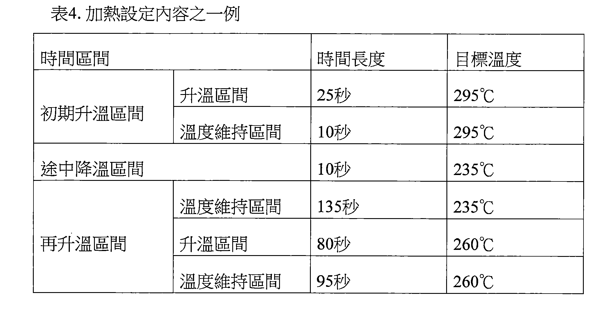
加熱設定內容可包含沿著時間軸連續的複數個時間區間。複數個時間區間係分別設定有時間區間之終期的目標溫度。並且,控制部116係於複數個時間區間之中,依據按照加熱設定內容進行的加熱部121之動作的控制開始起的經過時間的對應時間區間中設定的目標溫度與實際溫度之差距,來控制加熱部121之動作。具體而言,控制部116係將加熱部121之動作控制成在到達加熱設定內容中所包含的複數個時間區間各別的終期之前,達到所設定的目標溫度。以 下的表1顯示加熱設定內容之一例。 The heating setting content may include a plurality of time intervals that are continuous along the time axis. A plurality of time intervals are respectively set with target temperatures at the end of the time intervals. In addition, the control unit 116 controls the difference between the target temperature and the actual temperature set in the time interval corresponding to the elapsed time from the start of the control of the operation of the heating unit 121 according to the heating setting content in a plurality of time intervals. Operation of the heating unit 121 . Specifically, the control unit 116 controls the operation of the heating unit 121 so that the set target temperature is reached before reaching the end of each of the plurality of time intervals included in the heating setting content. by Table 1 below shows an example of the content of the heating setting.
[表1]

表1所示的加熱設定內容係依順序包含初期升溫區間、途中降溫區間及再升溫區間而由此等區間構成。表1所示之例中,初期升溫區間係加熱設定內容開始起至35秒後為止的區間。途中降溫區間係初期升溫區間之終期起至10秒後為止的區間。再升溫區間係從途中降溫區間之終期起至310秒後為止的區間。由於加熱設定內容包含此等時間區間,如以下說明,能夠從加熱設定內容之最初直至最後對使用者提供充分高品質的抽吸體驗。亦即,能夠讓使用者之抽吸體驗的品質提升。 The heating setting contents shown in Table 1 include an initial temperature rise section, an intermediate temperature drop section, and a reheat temperature section in this order, and are constituted by these sections. In the example shown in Table 1, the initial temperature increase section is a section from the start of the heating setting content to 35 seconds later. The midway temperature drop section is a section from the end of the initial temperature rise section to 10 seconds later. The re-heating section is a section from the end of the midway cooling section to 310 seconds later. Since the heating setting content includes such time intervals, as described below, a sufficiently high-quality puffing experience can be provided to the user from the beginning to the end of the heating setting content. That is, the quality of the user's smoking experience can be improved.
初始升溫區間係加熱設定內容之最初包含的時間區間。設定於初期升溫區間的目標溫度係高於初期溫度。所謂初期溫度係設定為加熱開始前的加熱部121之溫度的溫度。初期溫度之一例可為0℃等任意溫度。初期溫度之另一例可為對應於氣溫的溫度。 The initial temperature rise interval is the time interval included in the first heating setting content. The target temperature set in the initial temperature rise section is higher than the initial temperature. The initial temperature is the temperature set to the temperature of the heating unit 121 before the start of heating. An example of the initial temperature may be any temperature such as 0°C. Another example of the initial temperature may be the temperature corresponding to the air temperature.
如表1所示,初期升溫區間可依順序包含升溫區間及溫度維持區間。設定於初期升溫區間所包含之升溫區間的目標溫度係高於初期溫度。設定於溫度維持區間的目標溫度係與設定於溫度維持區間之前一個時間區間亦即升溫區間的目標溫度相同。 As shown in Table 1, the initial temperature rise interval may include a temperature rise interval and a temperature maintenance interval in sequence. The target temperature set in the temperature rise section included in the initial temperature rise section is higher than the initial temperature. The target temperature set in the temperature maintenance section is the same as the target temperature set in a time section before the temperature maintenance section, that is, the temperature increase section.
途中降溫區間係加熱設定內容之途中包含的時間區間。設定於途中降溫區間的目標溫度係低於設定於途中降溫區間之前一個時間區間的目標溫度。表1所示之例中,設定於途中降溫區間的目標溫度230℃係低於設定於前一個時間區間的初期升溫區間的目標溫度295℃。
The cooling section on the way is the time section included in the middle of heating the setting content. The target temperature set in the cooling down section on the way is lower than the target temperature set in a time section before the cooling down section on the way. In the example shown in Table 1, the
再升溫區間係加熱設定內容之最後所包含的時間區間。設定於再升溫區間的目標溫度係高於設定於再升溫區間之前一個時間區間的目標溫度。表1所示之例中,設定於再升溫區間的目標溫度260℃係高於設定於前一個時間區間的途中降溫區間的目標溫度230℃。 The reheating interval is the time interval included at the end of the heating setting content. The target temperature set in the reheating section is higher than the target temperature set in the time section before the reheating section. In the example shown in Table 1, the target temperature of 260° C. set in the re-heating section is higher than the target temperature of 230° C. set in the midway temperature drop section set in the previous time section.
如表1所示,再升溫區間可依順序包含溫度維持區間、升溫區間及溫度維持區間。設定於溫度維持區間的目標溫度係與設定於溫度維持區間之前一個時間區間的目標溫度相同。設定於升溫區間的目標溫度係高於設定於升溫區間之前一個時間區間的目標溫度。 As shown in Table 1, the re-heating interval may include a temperature maintaining interval, a temperature increasing interval, and a temperature maintaining interval in sequence. The target temperature set in the temperature maintenance section is the same as the target temperature set in a time section before the temperature maintenance section. The target temperature set in the temperature rise interval is higher than the target temperature set in a time interval before the temperature rise interval.
參照圖3說明控制部116按照表1所示之加熱設定內容控制加熱部121之動作時的加熱部121的實際溫度之時序變化。圖3係顯示依據表1所示之加熱設定內容而動作的加熱部121的實際溫度之時序變化之一例的曲線圖。本曲線圖之橫軸為時間(秒)。本曲線圖之縱軸為加熱部121之溫度。本曲線圖中的線21係表示加熱部121的實際溫度之時序變化。又,本曲線圖中的點22(22A至22F)係表示加熱設定內容中所規定的目標溫度。
3, the time series change of the actual temperature of the heating part 121 when the control part 116 controls the operation of the heating part 121 according to the heating setting content shown in Table 1 is demonstrated. FIG. 3 is a graph showing an example of a time-series change of the actual temperature of the heating unit 121 operated according to the heating setting contents shown in Table 1. FIG. The horizontal axis of this graph is time (seconds). The vertical axis of this graph is the temperature of the heating part 121 . The
如圖3所示,加熱部121之實際溫度係在初期升溫區間中上升,且在初期升溫區間之終期達到目標溫度的295℃。加熱部121之實際溫度已達到設定於初期升溫區間的目標溫度的情況下,認為棒型基材150之溫度達到可產生充分量之霧氣的溫度。初期升溫區間係設定於加熱設定內容之最初。因此,加熱部121係在初期升溫區間,從初期溫度一口氣升溫至設定於初期升溫區間的目標溫度的295℃。再者,所謂初期溫度係指依據加熱設定內容開始加熱時的加熱部121之實際溫度。藉由如此的構成,能夠盡快結束預備加熱。
As shown in FIG. 3 , the actual temperature of the heating unit 121 rises in the initial temperature rise section, and reaches 295° C. of the target temperature at the end of the initial temperature rise section. When the actual temperature of the heating part 121 has reached the target temperature set in the initial temperature rise section, it is considered that the temperature of the rod-shaped
若注目於初期升溫區間之細節,如圖3所示,加熱部121之實際溫度係在初期升溫區間之中,在升溫區間之終期達到目標溫度的295℃。並且,加熱部121之實際溫度係在後續之10秒的溫度維持區間,維持於295℃。依據如此的構成,可在溫度維持區間使棒型基材150至內部為止充分地升溫。因此,可防止由於棒型基材150至內部為止未充分地升溫所致之在後續之途中降溫區間及再升溫區間發生劣質之吸煙風味送達至使用者之事態。
If attention is paid to the details of the initial temperature rise interval, as shown in FIG. 3 , the actual temperature of the heating unit 121 is in the initial temperature rise interval, and reaches 295° C. of the target temperature at the end of the temperature rise interval. In addition, the actual temperature of the heating part 121 was maintained at 295° C. in the temperature maintenance section for the following 10 seconds. According to such a configuration, the temperature of the rod-shaped
控制部116係對於加熱部121進行溫度控制成為實際溫度在初期升溫區間中包含的升溫區間達到設定於該升溫區間的目標溫度。亦即,控制部116係將加熱部121之溫度控制成從初期溫度朝向295℃。若加熱開始起經過25秒之前,實際溫度已達到295℃時,控制部116係將加熱部121之溫度控制成維持於295℃。 The control unit 116 controls the temperature of the heating unit 121 so that the actual temperature reaches the target temperature set in the temperature increase area in the temperature increase area included in the initial temperature increase area. That is, the control part 116 controls the temperature of the heating part 121 from the initial temperature to 295 degreeC. When the actual temperature reaches 295°C before 25 seconds have elapsed from the start of heating, the control unit 116 controls the temperature of the heating unit 121 to be maintained at 295°C.
如圖3所示,加熱部121之實際溫度係在途中降溫區間降低,且在途中降溫區間之終期達到目標溫度的230℃。途中降溫區間係設定於初期升溫區間之下一個區間。因此,加熱部121係在途中降溫區間,從初期升溫區間之設定溫度暫時降溫至途中降溫區間之設定溫度。若將加熱部121維持於如初期升溫區
間的目標溫度之較高的溫度狀態,則棒型基材150中包含的霧氣源係急速地消耗,而可能發生使用者所品嚐之香味過強等缺失。對此,本實施型態中,藉由設置途中降溫區間來避免此種缺失,而可讓使用者之抽吸體驗的品質提升。
As shown in FIG. 3 , the actual temperature of the heating unit 121 is lowered during the cooling section on the way, and reaches 230° C. of the target temperature at the end of the cooling section on the way. The midway cooling interval is set at the interval below the initial heating interval. Therefore, the heating unit 121 is temporarily lowered from the set temperature in the initial temperature rise section to the set temperature in the midway temperature drop section in the middle temperature drop section. If the heating part 121 is maintained in the initial temperature rise region
If the temperature is higher than the target temperature between the two, the mist source contained in the rod-shaped
控制部116係在途中降溫區間進行不對加熱部121供電之控制。換句話說,控制部116係在途中降溫區間控制成為停止對加熱部121供電而不進行加熱部121的加熱。依據如此的構成,能夠使加熱部121之實際溫度最快地降低。並且,相較於途中降溫區間亦對加熱部121供電的情況,能夠減低吸嚐裝置100之消耗電力。 The control unit 116 controls the heating unit 121 not to supply power during the cooling section on the way. In other words, the control unit 116 controls the heating unit 121 to stop the power supply to the heating unit 121 without heating the heating unit 121 during the temperature drop section on the way. According to such a configuration, the actual temperature of the heating unit 121 can be lowered most quickly. In addition, compared with the case where the heating unit 121 is also supplied with power in the cooling section on the way, the power consumption of the tasting device 100 can be reduced.
如圖3所示,加熱部121之實際溫度係在再升溫度區域上升,且在再升溫區間之終期達到目標溫度的260℃。再升溫區間係設定於途中降溫區間之下一個區間,且設定於加熱設定內容之最後。因此,加熱部121係在再升溫區間,從途中降溫區間之設定溫度再度升溫至再升溫區間之設定溫度,之後停止加熱。若在初期升溫區間之後使加熱部121持續降溫,則由於棒型基材150亦會降溫,所以霧氣之生成量會降低,而可能導致使用者品嚐之香味劣化。對此,本實施型態中,藉由在途中降溫區間之後設置再升溫區間,故即便是加熱設定內容之後半,仍能夠防止使用者吸嚐之香味的劣化。
As shown in FIG. 3 , the actual temperature of the heating unit 121 rises in the re-heating temperature region, and reaches 260° C. of the target temperature at the end of the re-heating region. The re-heating interval is set at the next interval of the cooling interval on the way, and is set at the end of the heating setting content. Therefore, in the re-heating section, the heating unit 121 is heated again from the set temperature of the temperature-lowering section on the way to the set temperature of the re-heating section, and then stops heating. If the temperature of the heating part 121 is continuously lowered after the initial temperature rise interval, the rod-shaped
若注目於再升溫區間之細節,如圖3所示,加熱部121之實際溫度係在第一個溫度維持區間維持於230℃,在升溫區間達到260℃,在第二個溫度維持區間維持於260℃。依據如此的構成,霧氣會在再升溫區間緩慢地生成,所以能夠延長棒型基材150之壽命。並且,伴隨之,至再升溫區間之最後為止,都能夠從棒型基材150引出充分的香味。又,由於再升溫區間交替地包含溫度維持區間與升溫區間,因此,即便是實際溫度在溫度維持區間之前一個時間區間未達到
目標溫度的情況下,仍能夠使實際溫度在溫度維持區間接近目標溫度,所以能夠通過再升溫區間之全區間而提高實際溫度對目標溫度之追隨性。
If you pay attention to the details of the re-heating interval, as shown in FIG. 3 , the actual temperature of the heating unit 121 is maintained at 230°C in the first temperature maintenance interval, reaches 260°C in the temperature increase interval, and is maintained at 260°C in the second temperature maintenance interval. 260°C. According to such a configuration, the mist is gradually generated in the reheating section, so that the life of the rod-shaped
控制部116係將加熱部121之溫度控制成為實際溫度在再升溫區間包含的升溫區間達到設定於該升溫區間的目標溫度。亦即,控制部116係控制加熱部121之溫度朝向260℃。若從升溫區間之開始起經過80秒之前,實際溫度已到達260℃時,控制部116係將加熱部121之溫度控制成維持於260℃。 The control unit 116 controls the temperature of the heating unit 121 so that the actual temperature reaches the target temperature set in the temperature increase area in the temperature increase area included in the reheat temperature area. That is, the control part 116 controls the temperature of the heating part 121 toward 260 degreeC. When the actual temperature reaches 260°C before 80 seconds have elapsed from the start of the heating section, the control unit 116 controls the temperature of the heating unit 121 to maintain the temperature at 260°C.
(2)溫度測量表 (2) Temperature measuring table
加熱部121之電阻亦即構成加熱部121的發熱電阻器之電阻係對應於加熱部121之溫度變化而變化。因此,如上述說明,能夠依據加熱部121之電阻測量出加熱部121之溫度。更詳言之,控制部116係參照表示加熱部121之電阻與加熱部121之溫度的對應關係之資訊的溫度測量表,依據加熱部121之電阻來測量出加熱部121之溫度。以下的表2顯示溫度測量表之一例。 The resistance of the heating part 121 , that is, the resistance of the heating resistor constituting the heating part 121 changes according to the temperature change of the heating part 121 . Therefore, as described above, the temperature of the heating portion 121 can be measured based on the resistance of the heating portion 121 . More specifically, the control unit 116 refers to a temperature measurement table indicating the correspondence between the resistance of the heating unit 121 and the temperature of the heating unit 121 , and measures the temperature of the heating unit 121 according to the resistance of the heating unit 121 . Table 2 below shows an example of a temperature measurement table.
[表2]

上述表2中係顯示加熱部121藉由溫度越高則電阻越大的發熱電阻器構成時的溫度測量表。參照上述表2所示的溫度測量表之情況下,控制部116 係在加熱部121之電阻為3.0Q時,測量出加熱部121之實際溫度為295℃。 The above-mentioned Table 2 shows a temperature measurement table when the heating unit 121 is constituted by a heating resistor whose resistance increases as the temperature increases. When referring to the temperature measurement table shown in Table 2 above, the control unit 116 When the resistance of the heating part 121 is 3.0Q, the actual temperature of the heating part 121 is measured to be 295°C.
以下,將依據加熱部121之電阻所測量出的加熱部121之溫度亦稱為測量溫度。測量溫度係使用於依據加熱設定內容而進行之加熱部121之動作的控制。亦即,控制部116係將電源部111對加熱部121之供電控制成為測量溫度達到溫度條件中規定的目標溫度。更詳言之,控制部116係將加熱部121之溫度控制成為使測量溫度之時序變化與加熱設定內容所規定的目標溫度之時序變化相同。 Hereinafter, the temperature of the heating portion 121 measured based on the resistance of the heating portion 121 is also referred to as a measurement temperature. The measured temperature is used to control the operation of the heating unit 121 according to the heating setting content. That is, the control unit 116 controls the power supply from the power supply unit 111 to the heating unit 121 so that the measured temperature reaches the target temperature specified in the temperature condition. More specifically, the control unit 116 controls the temperature of the heating unit 121 so that the time-series change of the measured temperature is the same as the time-series change of the target temperature specified by the heating setting content.
(3)技術課題 (3) Technical issues
基本上認為實際溫度與測量溫度一致。此時,使測量溫度之時序變化與加熱設定內容中所規定的目標溫度之時序變化成為相同的方式進行控制時,實際溫度之時序變化與加熱設定內容中所規定的目標溫度之時序變化亦成為相同。此情況下,能夠將適當的香味送達至使用者。 Basically, the actual temperature is considered to be the same as the measured temperature. At this time, when the time-series change of the measured temperature and the time-series change of the target temperature specified in the heating setting content are controlled in the same manner, the time-series change of the actual temperature and the time-series change of the target temperature specified in the heating setting content also become same. In this case, an appropriate fragrance can be delivered to the user.
惟,加熱部121會隨著加熱次數增加而氧化,而有加熱部121之電阻變大的情況。此時,會在加熱部121之實際溫度與測量溫度之間產生誤差。 However, the heating portion 121 is oxidized as the number of heating times increases, and the resistance of the heating portion 121 may increase. At this time, an error occurs between the actual temperature of the heating unit 121 and the measured temperature.
例如,氧化前,實際溫度為295℃的情況下,電阻為3.0Ω。因此,參照表2所示的溫度測量表時,測量溫度係與實際溫度相同的295℃。然而,氧化後,實際溫度為295℃的情況下,電阻為例如3.1Ω。因此,參照表2所示的溫度測量表時,測量溫度係成為比實際溫度高5℃的300℃。此情況下,使測量溫度之時序變化與加熱設定內容中所規定的目標溫度之時序變化成為相同的方式進行控制時,實際溫度係比加熱設定內容中所規定的目標溫度之時序變化更變化低5℃。 For example, before oxidation, when the actual temperature is 295°C, the resistance is 3.0Ω. Therefore, when referring to the temperature measurement table shown in Table 2, the measured temperature is 295°C, which is the same as the actual temperature. However, after oxidation, when the actual temperature is 295° C., the resistance is, for example, 3.1Ω. Therefore, when referring to the temperature measurement table shown in Table 2, the measured temperature is 300°C higher than the actual temperature by 5°C. In this case, when the time series change of the measured temperature is controlled in the same way as the time series change of the target temperature specified in the heating setting content, the actual temperature will be lower than the time series change of the target temperature specified in the heating setting content. 5°C.
如此,氧化後亦進行與氧化前同樣之控制的情況下,會因實際溫 度與測量溫度之間產生的誤差量,使加熱部121之實際溫度達不到目標溫度。加熱部121之溫度達不到目標溫度時,可能會發生無法生成充分之霧氣等缺失。 In this way, when the same control as before oxidation is performed after oxidation, the actual temperature The amount of error generated between the temperature and the measured temperature makes the actual temperature of the heating unit 121 less than the target temperature. When the temperature of the heating part 121 does not reach the target temperature, there may be a defect such that a sufficient mist cannot be generated.
對此,本實施型態的吸嚐裝置100係即便在加熱部121氧化而電阻變大的情況下,依據後述的履歷值來控制加熱部121之動作,使加熱部121之實際溫度亦達到目標溫度。依據如此的構成,能夠防止起因於加熱部121氧化之吸嚐裝置100隨時間經過而劣化所引起的各種缺失發生。 On the other hand, even when the heating unit 121 is oxidized and the resistance increases, the inhalation device 100 of the present embodiment controls the operation of the heating unit 121 according to the history value described later, so that the actual temperature of the heating unit 121 also reaches the target. temperature. According to such a configuration, it is possible to prevent the occurrence of various defects caused by the deterioration of the tasting device 100 over time due to the oxidation of the heating portion 121 .
(4)依據履歷值之供電控制 (4) Power supply control based on historical value
控制部116係依據藉由加熱部121的加熱之執行來累計用以表示已藉由加熱部121所執行的加熱之履歷的履歷值。就一例而言,控制部116係在每次藉由加熱部121執行加熱時,累計用以表示已藉由加熱部121所執行的加熱之履歷的履歷值。就另一例而言,控制部116係在藉由加熱部121執行加熱達複數次(例如二次)時,累計用以表示已藉由加熱部121所執行的加熱之履歷的履歷值。如上述說明,加熱部121會隨著加熱次數增加而氧化,使得加熱部121之電阻變大。對此,若依據本發明的構成,則能夠藉由履歷值來掌握加熱部121之氧化的程度。 The control part 116 accumulates the history value which shows the history of the heating performed by the heating part 121 based on the execution of the heating by the heating part 121. For example, the control unit 116 accumulates a history value indicating the history of the heating performed by the heating unit 121 every time the heating unit 121 performs heating. In another example, the control unit 116 accumulates a history value indicating the history of the heating performed by the heating unit 121 when the heating unit 121 performs heating a plurality of times (eg, twice). As described above, the heating portion 121 is oxidized as the number of heating times increases, so that the resistance of the heating portion 121 increases. In contrast, according to the configuration of the present invention, the degree of oxidation of the heating portion 121 can be grasped from the history value.
履歷值亦可表示加熱部121裝設於吸嚐裝置100起,已藉由加熱部121所執行的加熱之履歷。換言之,履歷值亦可表示吸嚐裝置100製造完成起的加熱之履歷。若考量到加熱部121之氧化係從製造時就已開始時,依據本發明的構成,就能夠藉由履歷值正確地掌握加熱部121之氧化的程度。 The history value may also indicate the history of the heating performed by the heating unit 121 since the heating unit 121 was installed in the inhalation device 100 . In other words, the history value can also represent the history of heating since the production of the tasting device 100 is completed. Considering that the oxidation of the heating part 121 has been started from the time of manufacture, according to the configuration of the present invention, the degree of oxidation of the heating part 121 can be accurately grasped from the history value.
就一例而言,履歷值亦可為加熱部121加熱的次數(以下亦稱為加熱次數)之累計值。可在依據加熱設定內容的加熱每進行一次時,於履歷值中累計1。亦即,履歷值亦可為加熱部121依據加熱設定內容而加熱的次數之累計值。依據加熱設定內容進行加熱一次的期間中,會有進行複數次短時間的加熱之執 行及停止的情況,亦可在該短時間的加熱每執行一次時於履歷值中累計1。無論如何,都能夠依據加熱次數來掌握加熱部121之氧化的程度。 As an example, the history value may be an accumulated value of the number of times of heating by the heating unit 121 (hereinafter also referred to as the number of times of heating). It is possible to accumulate 1 in the history value every time the heating according to the heating setting content is performed. That is, the history value may also be an accumulated value of the number of times the heating unit 121 heats according to the heating setting content. During the period of heating once according to the heating setting, it may be necessary to perform heating several times for a short period of time. In the case of running and stopping, 1 can be accumulated in the history value every time the short-time heating is executed. In any case, the degree of oxidation of the heating part 121 can be grasped according to the number of heating times.
就另一例而言,履歷值亦可為加熱部121加熱的時間(以下亦稱為加熱時間)之累計值。可在依據加熱設定內容的加熱每進行一次時,將依據加熱設定內容的加熱一次經過的時間累計於履歷值。依據加熱設定內容的加熱進行一次的期間,會有進行複數次短時間的加熱之執行及停止的情況,亦可僅將該短時間之加熱的經過時間累計於履歷值。無論如何,都能夠依據加熱時間來掌握加熱部121之氧化的程度。 In another example, the history value may be an accumulated value of the heating time of the heating unit 121 (hereinafter also referred to as heating time). Each time the heating according to the heating setting content is performed once, the elapsed time of one heating according to the heating setting content can be accumulated in the history value. While the heating according to the heating setting content is performed once, the execution and stop of the short-time heating may be performed several times, and only the elapsed time of the short-time heating may be accumulated in the history value. In any case, the degree of oxidation of the heating part 121 can be grasped according to the heating time.
控制部116係依據所累計的履歷值來控制加熱部121之動作。依據如此的構成,則能夠對應於履歷值所示的加熱部121之氧化的程度來控制加熱部121的加熱。因此,能夠防止起因於加熱部121之氧化所引起的缺失發生。 The control part 116 controls the operation|movement of the heating part 121 based on the accumulated history value. According to such a structure, the heating of the heating part 121 can be controlled according to the degree of oxidation of the heating part 121 shown by the history value. Therefore, it is possible to prevent occurrence of defects due to oxidation of the heating portion 121 .
具體而言,控制部116係依據履歷值來更新加熱設定內容,且依據更新後的加熱設定內容來控制加熱部121之動作。就一例而言,控制部116係將加熱設定內容更新為加熱量比更新前更增加,以藉由加熱量之增加來抵銷因加熱部121之氧化所引起的加熱量之降低,而可實現加熱部121之氧化前後無變化的加熱。因此,能夠防止起因於加熱部121之氧化所引起的缺失發生。 Specifically, the control unit 116 updates the heating setting content according to the history value, and controls the operation of the heating unit 121 according to the updated heating setting content. In one example, the control unit 116 updates the heating setting content so that the heating amount is increased more than before the update, so that the increase in the heating amount can offset the decrease in the heating amount caused by the oxidation of the heating unit 121, so that it can be realized. The heating of the heating part 121 does not change before and after oxidation. Therefore, it is possible to prevent occurrence of defects due to oxidation of the heating portion 121 .
控制部116係依據履歷值,將加熱設定內容所規定的複數個目標溫度中之至少一部分的目標溫度之更新對象的目標溫度,更新成更高的溫度,且依據更新後的加熱設定內容來控制加熱部121之動作。如上述說明,加熱部121隨著加熱次數增加而氧化,使得加熱部121之電阻變大時,測量溫度會比實際溫度更高。因此,按照更新前之加熱設定內容進行控制之情況下,加熱部121之實際溫度會因實際溫度與測量溫度之間產生的誤差量而達不到目標溫度。對此,藉由 將目標溫度更新成更高的溫度,而朝向更新後之目標溫度來控制加熱部121之溫度,就能使升溫達測量溫度與實際溫度之間產生的誤差量,而使實際溫度到達更新前之目標溫度。 The control unit 116 updates the target temperature of at least a part of the target temperature of the target temperature specified in the heating setting content to a higher temperature based on the history value, and controls the heating setting content after the update. Operation of the heating unit 121 . As described above, the heating portion 121 is oxidized as the number of heating times increases, so that when the resistance of the heating portion 121 increases, the measured temperature will be higher than the actual temperature. Therefore, when the control is performed according to the heating setting content before updating, the actual temperature of the heating unit 121 may not reach the target temperature due to the amount of error generated between the actual temperature and the measured temperature. For this, by The target temperature is updated to a higher temperature, and the temperature of the heating unit 121 is controlled toward the updated target temperature, so that the temperature can be increased by the error amount generated between the measured temperature and the actual temperature, and the actual temperature can be reached before the update. target temperature.
就一例而言,假定測量溫度與實際溫度之間產生5℃程度的誤差之情況,控制部116可將表1所示之加熱設定內容所規定的複數個目標溫度中之全部的目標溫度作為更新對象之目標溫度,分別提高5℃來更新。表3顯示如此的更新後的加熱設定內容之一例。 As an example, assuming that an error of about 5°C occurs between the measured temperature and the actual temperature, the control unit 116 may update all the target temperatures among the plurality of target temperatures specified by the heating setting contents shown in Table 1 as update. The target temperature of the object is updated by increasing it by 5°C. Table 3 shows an example of such updated heating setting contents.
[表3]

表3所示的加熱設定內容係從表1所示的加熱設定內容將所有的目標溫度皆分別提升5℃。因此,例如初始升溫區間中,控制部116係將加熱部121之動作控制成所測量到的加熱部121之溫度達到更新後之目標溫度的300℃。換句話說,控制部116係在加熱設定內容之更新前,以加熱部121之電阻達到3.0Ω的方式來進行控制,相對於此,在加熱設定內容之更新後,以加熱部121之電阻達到3.1Ω的方式來進行控制。測量溫度與實際溫度之間產生5℃程度之誤差的情
況下,藉由如此的構成,能夠使加熱部121之實際溫度到達更新前之目標溫度的295℃。因此,能夠防止起因於加熱部121之氧化所引起的缺失發生。
The heating setting content shown in Table 3 is obtained by raising all the target temperatures by 5°C from the heating setting content shown in Table 1. Therefore, for example, in the initial temperature rise interval, the control unit 116 controls the operation of the heating unit 121 so that the measured temperature of the heating unit 121
參照圖4說明測量溫度與實際溫度之間產生5℃程度之誤差的狀況下,控制部116按照表3所示之加熱設定內容來控制加熱部121之動作時之加熱部121的實際溫度之時序變化。圖4係顯示測量溫度與實際溫度之間產生5℃程度之誤差的狀況下,依據表3所示之加熱設定內容而動作的加熱部121的實際溫度之時序變化之一例的曲線圖。本曲線圖之橫軸為時間(秒)。本曲線圖之縱軸為加熱部121之溫度。本曲線圖中的線21係表示加熱部121的實際溫度之時序變化。又,本曲線圖中的點22(22A至22F)係表示加熱設定內容中所規定的目標溫度。
Referring to FIG. 4 , when an error of about 5°C occurs between the measured temperature and the actual temperature, the control unit 116 controls the actual temperature sequence of the heating unit 121 when the operation of the heating unit 121 is controlled according to the heating setting content shown in Table 3. Variety. 4 is a graph showing an example of a time series change of the actual temperature of the heating unit 121 that operates according to the heating settings shown in Table 3 when an error of about 5°C occurs between the measured temperature and the actual temperature. The horizontal axis of this graph is time (seconds). The vertical axis of this graph is the temperature of the heating part 121 . The
如圖4所示,使測量溫度之時序變化與加熱設定內容所規定的目標溫度之時序變化成為相同的方式進行控制的結果,實際溫度會以比目標溫度低5℃的狀態變化,故線21所示的實際溫度之時序變化係通過比點22A至22F所示的目標溫度分別低5℃的溫度。結果,圖4中之線21所示的實際溫度之時序變化係成為與表1所示的更新前之加熱設定內容所示的目標溫度之時序變化相同。如此,即便是加熱部121氧化之後,仍能夠實現與更新前之加熱設定內容所規定的目標溫度之時序變化同樣的實際溫度之時序變化。
As shown in Fig. 4, the time series change of the measured temperature and the time series change of the target temperature specified by the heating setting content are controlled in the same way, and the actual temperature will change in a state lower than the target temperature by 5°C, so
控制部116亦可在履歷值超過預定臨限值時更新加熱設定內容。就一例而言,控制部116可在加熱次數超過1000次時更新加熱設定內容。例如,控制部116可在加熱次數超過1000次之前使用表1所示的加熱設定內容,而在加熱次數超過1000次時更新成表3所示的加熱設定內容。就另一例而言,控制部116可在加熱時間每經過十萬秒時更新加熱設定內容。依據如此的構成,能抑制加熱設定內容之更新頻率,而能夠減輕控制部116之處理負荷。 The control unit 116 may update the heating setting content when the history value exceeds a predetermined threshold value. For example, the control unit 116 may update the heating setting content when the number of heating times exceeds 1000 times. For example, the control unit 116 may use the heating setting contents shown in Table 1 until the heating frequency exceeds 1000 times, and update the heating setting contents shown in Table 3 when the heating frequency exceeds 1000 times. In another example, the control unit 116 may update the heating setting content every 100,000 seconds of the heating time. According to such a structure, the update frequency of the heating setting content can be suppressed, and the processing load of the control part 116 can be reduced.
控制部116亦可在每次累計履歷值時更新加熱設定內容。就一例而言,控制部116可每次在加熱次數被累計時更新加熱設定內容。例如,控制部116係在每次累計加熱次數時,對更新前之目標溫度加上或乘上修正值。如此的修正值可對應於加熱次數而增加。就另一例而言,控制部116亦可在每次累計加熱時間時更新加熱設定內容。依據如此的構成,能在每次累計履歷值時更新加熱設定內容,所以能夠恆常地防止起因於加熱部121之氧化而引起的缺失發生。 The control unit 116 may update the heating setting content every time the history value is accumulated. For example, the control unit 116 may update the heating setting content every time the number of heating times is accumulated. For example, the control unit 116 adds or multiplies the correction value to the target temperature before updating each time the number of times of heating is accumulated. Such a correction value may be increased corresponding to the number of heating times. In another example, the control unit 116 may update the heating setting content every time the heating time is accumulated. According to such a configuration, since the heating setting content can be updated every time the history value is accumulated, it is possible to constantly prevent occurrence of a defect caused by the oxidation of the heating part 121 .
上述說明中已說明了以加熱設定內容所規定的全部目標溫度皆成為更新對象之目標溫度且進行更新之例,惟本發明不限於如此之例。亦可為加熱設定內容所規定的複數個目標溫度中的一部分成為更新對象之目標溫度。以下說明加熱設定內容的更新方法之其他態樣。 In the above description, an example has been described in which all the target temperatures specified in the heating setting content are the target temperatures to be updated and updated, but the present invention is not limited to this example. A part of a plurality of target temperatures specified for the heating setting content may be the target temperature to be updated. Another aspect of the update method of the heating setting content will be described below.
包含最低之目標溫度的目標溫度之更新 Updated target temperature with minimum target temperature
更新對象之目標溫度亦可包含加熱設定內容所規定的複數個目標溫度中的最低之目標溫度。亦即,控制部116亦可將包含加熱設定內容所規定的複數個目標溫度中的最低之目標溫度的一部分之目標溫度更新成更高的溫度。就一例而言,假定測量溫度與實際溫度之間產生5℃程度之誤差的情況下,控制部116可將表1所示之加熱設定內容所規定的複數個目標溫度中的最低之目標溫度的230℃更新成提高5℃的溫度。表4顯示更新後的加熱設定內容之一例。 The target temperature to be updated may also include the lowest target temperature among a plurality of target temperatures specified in the heating setting content. That is, the control unit 116 may update the target temperature including a part of the lowest target temperature among the plurality of target temperatures specified by the heating setting content to a higher temperature. As an example, assuming that an error of about 5°C occurs between the measured temperature and the actual temperature, the control unit 116 may determine the lowest target temperature among a plurality of target temperatures specified by the heating setting contents shown in Table 1. 230°C was updated to a temperature increase of 5°C. Table 4 shows an example of the updated heating setting contents.
[表4]
參照圖5說明測量溫度與實際溫度之間產生5℃程度之誤差的狀況下,控制部116按照表4所示之加熱設定內容來控制加熱部121之動作時之加熱部121的實際溫度之時序變化。圖5係顯示測量溫度與實際溫度之間產生5℃程度之誤差的狀況下,依據表4所示之加熱設定內容而動作的加熱部121的實際溫度之時序變化之一例的曲線圖。本曲線圖之橫軸為時間(秒)。本曲線圖之縱軸為加熱部121之溫度。本曲線圖中的線21係表示加熱部121的實際溫度之時序變化。又,本曲線圖中的點22(22A至22F)係表示加熱設定內容中所規定的目標溫度。
Referring to FIG. 5 , when an error of about 5° C. occurs between the measured temperature and the actual temperature, the control unit 116 controls the actual temperature sequence of the heating unit 121 when the operation of the heating unit 121 is controlled according to the heating setting content shown in Table 4. Variety. 5 is a graph showing an example of a time series change of the actual temperature of the heating unit 121 that operates according to the heating settings shown in Table 4 when an error of about 5°C occurs between the measured temperature and the actual temperature. The horizontal axis of this graph is time (seconds). The vertical axis of this graph is the temperature of the heating part 121 . The
如圖5所示,線21所示的實際溫度之時序變化係通過比點22A至22F所示的目標溫度分別低5℃的溫度。在此,比較表4所示的更新後之加熱設定內容與表1所示的更新前之加熱設定內容時,設定於途中降溫區間及再升溫區間中所包含的第一個溫度維持區間之目標溫度係分別更新成高5℃的目標溫度。結果,圖5中之線21所示的實際溫度之時序變化係在途中降溫區間及再升溫區間中
所包含的第一個溫度維持區間,成為與表1所示的更新前之加熱設定內容所示的目標溫度之時序變化相同。如此,即便是加熱部121氧化之後,就加熱設定內容所規定的目標溫度中的最低之目標溫度而言,仍能夠實現與更新前之加熱設定內容所規定的目標溫度之時序變化同樣的實際溫度之時序變化。
As shown in FIG. 5, the time-series variation of the actual temperature shown by
亦可能有加熱部121之氧化比想像的情況更緩慢亦即加熱部121之電阻未成為比想像的電阻更大的情況。此時,測量溫度與實際溫度之間的誤差係小於想像的情況。如此的狀態下,若將加熱設定內容更新,而將加熱部121之溫度控制成朝向比更新前更高的目標溫度時,由於測量溫度與實際溫度之間的誤差小於想像的情況,所以實際溫度會超過更新前之目標溫度而變得更高。因此,如初期升溫區間的目標溫度之本來就較高的目標溫度更進一步變高時,實際溫度會變得過高,而恐有對吸嚐裝置100之功能造成損傷之虞。對此,藉由限定以加熱設定內容所規定的複數個目標溫度中的最低之目標溫度進行更新,而能夠來防止如此的缺失。 The oxidation of the heating portion 121 may be slower than expected, that is, the resistance of the heating portion 121 may not be greater than expected. At this time, the error between the measured temperature and the actual temperature is smaller than imagined. In such a state, if the heating setting content is updated and the temperature of the heating unit 121 is controlled to a higher target temperature than before the update, the error between the measured temperature and the actual temperature is smaller than expected, so the actual temperature will be higher than the target temperature before the update. Therefore, if the target temperature in the initial temperature rise interval, which is originally high, is further increased, the actual temperature will become too high, which may damage the function of the inhalation device 100 . On the other hand, by limiting and updating the lowest target temperature among a plurality of target temperatures specified by the heating setting content, such a loss can be prevented.
又,就起因於加熱部121之氧化的缺失而言,可列舉如即使是加熱中,棒型基材15之溫度亦過度降低而無法生成霧氣。並且,最有可能發生如此之缺失的階段,係加熱設定內容中,目標溫度設定為最低的階段。對此,能夠藉由將加熱設定內容所規定的複數個目標溫度中的最低之目標溫度更新成更高的溫度來防止如此的缺失發生。 Moreover, even if it is heating, the temperature of the rod-shaped base material 15 falls too much and cannot generate|occur|produce mist, for example in the absence of the oxidation which originates in the heating part 121. In addition, the stage in which such a loss is most likely to occur is the stage in which the target temperature is set to the lowest among the heating setting contents. On the other hand, by updating the lowest target temperature among the plurality of target temperatures specified by the heating setting content to a higher temperature, such a loss can be prevented from occurring.
包含預定臨限值以下之目標溫度的目標溫度之更新 Update of target temperature including target temperature below predetermined threshold
更新對象之目標溫度亦可包含加熱設定內容所規定的複數個目標溫度中之預定臨限值以下之目標溫度。亦即,控制部116亦可將包含加熱設定內容所規定的複數個目標溫度中之預定臨限值以下之目標溫度的一部分之目標溫度更新成 更高的溫度。就一例而言,於表5顯示更新後的加熱設定內容之一例,將表1所示之加熱設定內容所規定的複數個目標溫度中之260℃以下的目標溫度提高5℃的溫度。 The target temperature to be updated may also include a target temperature below a predetermined threshold value among a plurality of target temperatures specified by the heating setting content. That is, the control unit 116 may update the target temperature including a part of the target temperature below the predetermined threshold value among the plurality of target temperatures specified by the heating setting content to higher temperature. As an example, Table 5 shows an example of the updated heating setting contents, and the target temperature of 260° C. or lower among the plurality of target temperatures specified in the heating setting contents shown in Table 1 is increased by 5° C.
[表5]

參照圖6說明測量溫度與實際溫度之間產生5℃程度之誤差的狀況下,控制部116按照表5所示之加熱設定內容來控制加熱部121之動作時之加熱部121的實際溫度之時序變化。圖6係顯示測量溫度與實際溫度之間產生5℃程度之誤差的狀況下,依據表5所示之加熱設定內容而動作的加熱部121的實際溫度之時序變化之一例的曲線圖。本曲線圖之橫軸為時間(秒)。本曲線圖之縱軸為加熱部121之溫度。本曲線圖中的線21係表示加熱部121的實際溫度之時序變化。又,本曲線圖中的點22(22A至22F)係表示加熱設定內容中所規定的目標溫度。
Referring to FIG. 6 , when an error of about 5°C occurs between the measured temperature and the actual temperature, the control unit 116 controls the actual temperature sequence of the heating unit 121 when the operation of the heating unit 121 is controlled according to the heating setting content shown in Table 5. Variety. 6 is a graph showing an example of a time series change of the actual temperature of the heating unit 121 that operates according to the heating settings shown in Table 5 when an error of about 5°C occurs between the measured temperature and the actual temperature. The horizontal axis of this graph is time (seconds). The vertical axis of this graph is the temperature of the heating part 121 . The
如圖6所示,線21所示的實際溫度之時序變化係通過比點22A至22F所示的目標溫度分別低5℃的溫度。在此,比較表5所示的更新後之加熱設定
內容與表1所示的更新前之加熱設定內容時,設定於途中降溫區間及再升溫區間的目標溫度係分別更新成高5℃的目標溫度。結果,圖6中之線21所示的實際溫度之時序變化係在途中降溫區間及再升溫區間之全區間中,成為與表1所示的更新前之加熱設定內容所示的目標溫度之時序變化相同。如此,即便是加熱部121氧化之後,就加熱設定內容所規定的目標溫度中之預定臨限值以下之目標溫度而言,仍能夠實現與更新前之加熱設定內容所規定的目標溫度之時序變化同樣的實際溫度之時序變化。
As shown in FIG. 6, the time-series variation of the actual temperature shown by
與將最低之目標溫度更新成更高的溫度時同樣地,將預定臨限值以下之目標溫度更新成更高的溫度時,可防止實際溫度變得過高或是因溫度過低而無法生成霧氣等上述的缺失發生。 In the same way as when updating the lowest target temperature to a higher temperature, when updating the target temperature below the predetermined threshold value to a higher temperature, it is possible to prevent the actual temperature from becoming too high or being too low to be generated. The above-mentioned deficiencies such as fog occur.
特定的目標溫度之更新 Updates to specific target temperatures
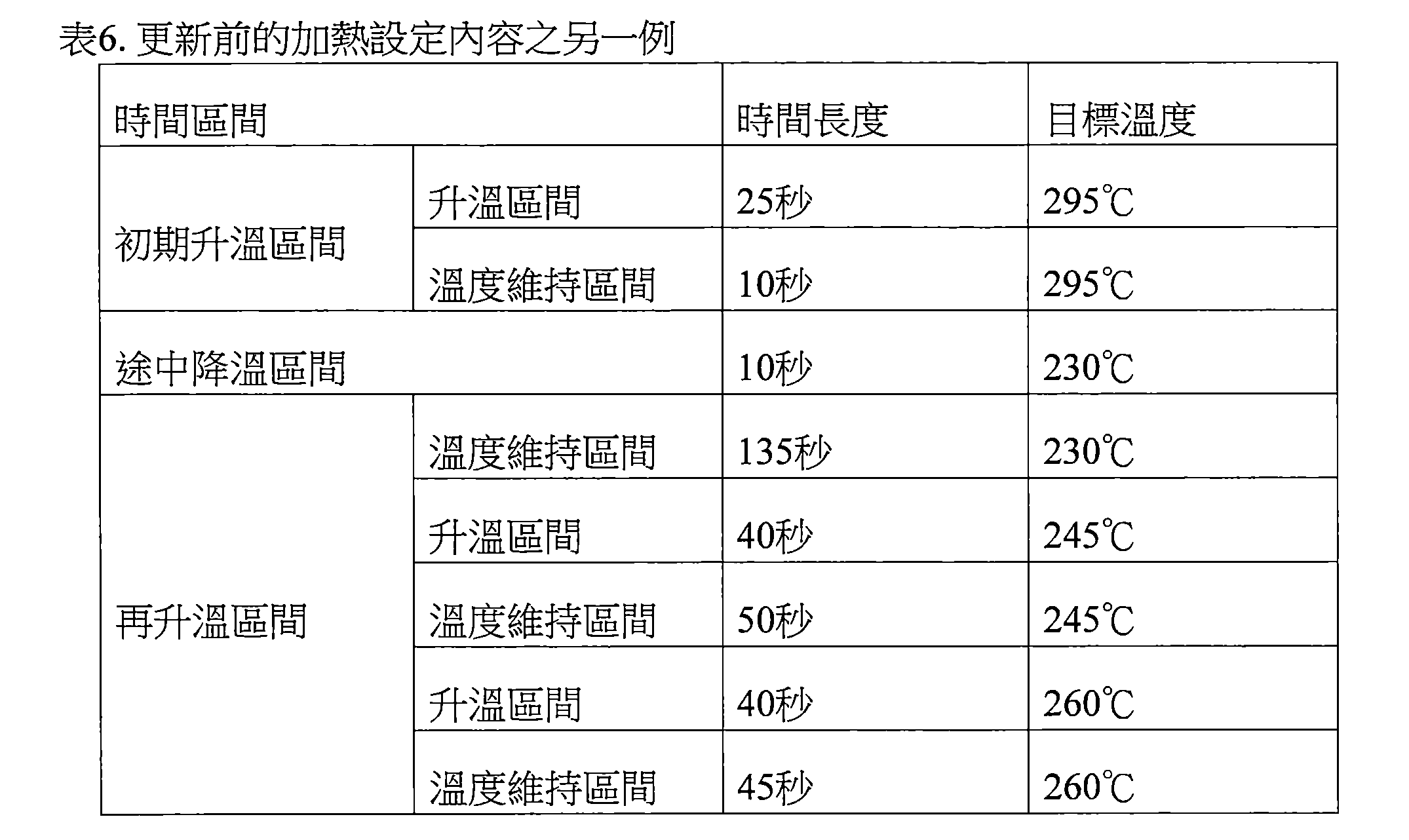
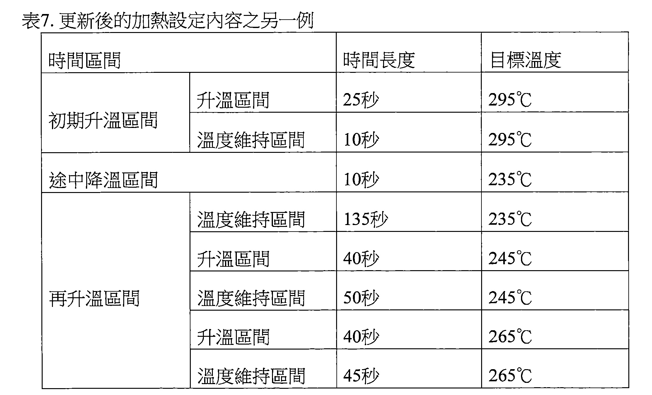
亦可將任意選定之特定的目標溫度作為更新對象之目標溫度進行更新。就一例而言,假定測量溫度與實際溫度之間產生5℃程度之誤差的情況,控制部116可將表6所示的加熱設定內容更新成表7所示的加熱設定內容。在此,控制部116係將表6所示之加熱設定內容所規定的複數個目標溫度中的最低之目標溫度的230℃以及倒數第三低之目標溫度的260℃更新成提高5℃的溫度。亦即,控制部116並未更新倒數第二低之目標溫度的245℃。 It is also possible to update any specific target temperature selected as the target temperature of the update object. As an example, the control unit 116 may update the heating setting content shown in Table 6 to the heating setting content shown in Table 7, assuming that an error of about 5° C. occurs between the measured temperature and the actual temperature. Here, the control unit 116 updates the lowest target temperature of 230° C. and the third lowest target temperature of 260° C. among the plurality of target temperatures specified by the heating setting contents shown in Table 6 to a temperature increased by 5° C. . That is, the control unit 116 does not update the target temperature of 245°C, which is the second lowest from the end.
[表6]
[表7]
當然,更新對象之目標溫度的選定方法不限於上述者。更新對象 之目標溫度亦可依據時間來選定而非依據溫度來選定。例如,亦可將設定於加熱設定內容中之特定的一部分之時間區間的目標溫度作為更新對象之目標溫度。 Of course, the method for selecting the target temperature of the update object is not limited to the above. update object The target temperature can also be selected based on time rather than temperature. For example, the target temperature set in the time interval of a specific part of the heating setting contents may be used as the target temperature to be updated.
目標溫度之逐次更新 Sequential update of target temperature
控制部116亦可隨著履歷值的累計,將更新對象之目標溫度從較低之目標溫度開始依順序更新。就一例而言,可考慮加熱設定內容所規定的複數個目標溫度皆為更新對象的情況。此時,控制部116係隨著履歷值的累計,從最低之目標溫度至最高之目標溫度,每次選擇一個目標溫度,將所選擇的目標溫度更新成更高的溫度。藉此,隨著履歷值的累計,增加更新的目標溫度之數目。 The control unit 116 may sequentially update the target temperature of the update object from the lower target temperature in accordance with the accumulation of the history value. As an example, it is conceivable that a plurality of target temperatures specified in the heating setting contents are all targeted for updating. At this time, the control unit 116 selects one target temperature each time from the lowest target temperature to the highest target temperature along with the accumulation of the history value, and updates the selected target temperature to a higher temperature. Thereby, the number of target temperatures to be updated is increased along with the accumulation of the history value.
具體而言,控制部116可隨著履歷值的累計,而依設定於途中降溫區間的目標溫度、設定於再升溫區間的目標溫度、設定於初期升溫區間的目標溫度之順序進行更新。例如,控制部116係在履歷值為第一臨限值以下時,使用表1所示的初期之加熱設定內容(亦即更新前的加熱設定內容)。接著,控制部116係在履歷值超過第一臨限值時,更新成使用表4所示的加熱設定內容。再者,控制部116係在履歷值超過比第一臨限值更大之第二臨限值時,更新成使用表5所示的加熱設定內容。進而,控制部116係在履歷值超過比第二臨限值更大之第三臨限值時,更新成使用表3所示的加熱設定內容。 Specifically, the control unit 116 may update the target temperature set in the midway cooling section, the target temperature set in the re-heating section, and the target temperature set in the initial heating section in the order of accumulation of the history value. For example, when the history value is equal to or less than the first threshold value, the control unit 116 uses the initial heating setting contents shown in Table 1 (that is, the heating setting contents before updating). Next, when the history value exceeds the first threshold value, the control unit 116 updates the heating setting contents shown in Table 4 to be used. In addition, when the history value exceeds the second threshold value larger than the first threshold value, the control unit 116 updates the heating setting contents shown in Table 5 to be used. Furthermore, when the history value exceeds the third threshold value larger than the second threshold value, the control unit 116 updates the heating setting contents shown in Table 3 to be used.
依據如此的構成,在更新比較低之目標溫度的階段,可防止實際溫度變得過高或是溫度過低而無法生成霧氣等上述的缺失發生。並且,在進展至更新比較高之目標溫度的階段時,能夠通過加熱設定內容之全區間實現與更新前之加熱設定內容所規定的目標溫度之時序變化同樣的實際溫度之時序變化。藉此,能夠將適當的香味送達至使用者。 According to such a configuration, at the stage of updating the relatively low target temperature, it is possible to prevent the occurrence of the above-mentioned failures, such as the actual temperature becoming too high or the temperature being too low to generate mist. Furthermore, when progressing to the stage of updating a relatively high target temperature, the same time-series change of the actual temperature as the time-series change of the target temperature prescribed by the heating setting content before the update can be realized through the entire range of the heating setting content. Thereby, an appropriate fragrance can be delivered to the user.
就另一例而言,可考慮加熱設定內容所規定的複數個目標溫度之 一部分為更新對象的情況。此時,控制部116係隨著履歷值的累計,從更新對象之目標溫度中的最低之目標溫度至最高之目標溫度,每次選擇一個目標溫度,將所選擇的目標溫度更新成更高的溫度。即便是如此的構成中,仍能夠與上述同樣地將適當的香味送達至使用者。 As another example, it is possible to consider the number of target temperatures specified by the heating setting content. Part of it is the case of updating objects. At this time, the control unit 116 selects one target temperature each time from the lowest target temperature to the highest target temperature among the target temperatures to be updated, and updates the selected target temperature to a higher target temperature according to the accumulation of the history values. temperature. Even in such a configuration, it is possible to deliver an appropriate fragrance to the user in the same manner as described above.
(5)處理的流程 (5) Process flow
圖7係顯示本實施型態的吸嚐裝置100所執行之處理的流程之一例的流程圖。 FIG. 7 is a flowchart showing an example of the flow of processing performed by the tasting device 100 of the present embodiment.
如圖7所示,首先,感測器部112係檢測指示加熱開始的操作(步驟S102)。 As shown in FIG. 7 , first, the sensor unit 112 detects an operation instructing the start of heating (step S102 ).
接著,控制部116係判定履歷值是否為第一臨限值以下(步驟S104)。履歷值之一例為加熱次數。第一臨限值之一例為1000次。 Next, the control unit 116 determines whether or not the history value is equal to or less than the first threshold value (step S104). An example of the history value is the number of heating times. An example of the first threshold value is 1000 times.
判定履歷值為第一臨限值以下時(步驟S140:是),控制部116係開始依據初期之加熱設定內容控制加熱部121之動作(步驟S106)。例如,控制部116係依據表1所示的加熱設定內容來控制加熱部121之動作。之後,處理係前進至步驟S118。 When it is determined that the history value is equal to or less than the first threshold value (step S140: YES), the control unit 116 starts to control the operation of the heating unit 121 according to the initial heating setting content (step S106). For example, the control unit 116 controls the operation of the heating unit 121 according to the heating setting contents shown in Table 1. After that, the process proceeds to step S118.
判定履歷值超過第一臨限值時(步驟S104:否),控制部116係判定履歷值是否為第二臨限值以下(步驟S108)。第二臨限值之一例為2000次。 When it is determined that the history value exceeds the first threshold value (step S104: NO), the control unit 116 determines whether or not the history value is equal to or less than the second threshold value (step S108). An example of the second threshold value is 2000 times.
判定履歷值為第二臨限值以下時(步驟S108:是),控制部116係將初期之加熱設定內容中的最低之目標溫度更新成更高的溫度,且開始依據更新後之加熱設定內容控制加熱部121之動作(步驟S110)。例如,控制部116係依據表4所示的加熱設定內容來控制加熱部121之動作。之後,處理係前進至步驟S118。 When it is determined that the history value is less than or equal to the second threshold value (step S108: YES), the control unit 116 updates the lowest target temperature in the initial heating setting content to a higher temperature, and starts according to the updated heating setting content The operation of the heating unit 121 is controlled (step S110). For example, the control unit 116 controls the operation of the heating unit 121 according to the heating setting contents shown in Table 4. After that, the process proceeds to step S118.
判定履歷值超過第二臨限值時(步驟S108:否),控制部116係判定 履歷值是否為第三臨限值以下(步驟S112)。第三臨限值之一例為3000次。 When it is determined that the history value exceeds the second threshold value (step S108: NO), the control unit 116 determines that Whether or not the history value is equal to or less than the third threshold value (step S112). An example of the third threshold value is 3000 times.
判定履歷值為第三臨限值以下時(步驟S112:是),控制部116係將初期之加熱設定內容中的預定臨限值以下之目標溫度更新成更高溫,且開始依據更新後之加熱設定內容控制加熱部121之動作(步驟S114)。例如,控制部116係依據表5所示的加熱設定內容來控制加熱部121之動作。之後,處理係前進至步驟S118。 When it is determined that the history value is equal to or less than the third threshold value (step S112: YES), the control unit 116 updates the target temperature that is equal to or less than the predetermined threshold value in the initial heating setting content to a higher temperature, and starts heating according to the update. The setting content controls the operation of the heating unit 121 (step S114). For example, the control unit 116 controls the operation of the heating unit 121 according to the heating setting contents shown in Table 5. After that, the process proceeds to step S118.
判定履歷值超過第三臨限值時(步驟S112:否),控制部116係將初期之加熱設定內容中之全部的目標溫度更新成更高的溫度,且開始依據更新後之加熱設定內容控制加熱部121之動作(步驟S116)。例如,控制部116係依據表3所示的加熱設定內容來控制加熱部121之動作。之後,處理係前進至步驟S118。 When it is determined that the history value exceeds the third threshold value (step S112: NO), the control unit 116 updates all the target temperatures in the initial heating setting content to a higher temperature, and starts control according to the updated heating setting content Operation of the heating unit 121 (step S116). For example, the control unit 116 controls the operation of the heating unit 121 according to the heating setting contents shown in Table 3. After that, the process proceeds to step S118.
步驟S118中,控制部116係累計履歷值(步驟S118)。例如,控制部116係使履歷值遞增。 In step S118, the control unit 116 accumulates the history values (step S118). For example, the control unit 116 increments the history value.
<<3.變化例>> <<3. Variations>>
(1)第一變化例 (1) First variation example
上述實施型態中已說明了控制部116依據履歷值更新加熱設定內容之例。如此之例中,藉由更新加熱設定內容來吸收起因於加熱部121之氧化而在測量溫度與實際溫度之間產生的誤差。然而,本發明不限於如此之例。例如,控制部116亦可依據履歷值來更新規定加熱部121之電阻與加熱部121之溫度的關係的溫度測量表。並且,控制部116可依據更新後之溫度測量表來測量加熱部121之溫度,且將加熱部121之動作控制成所測定的加熱部121之溫度達到加熱設定內容所規定的目標溫度。依據如此的構成,能夠藉由更新溫度測量表來吸收起因於加熱部121之氧化而在測量溫度與實際溫度之間產生的誤差。 In the above-mentioned embodiment, the example in which the control unit 116 updates the heating setting content based on the history value has been described. In such an example, the error between the measured temperature and the actual temperature caused by the oxidation of the heating part 121 is absorbed by updating the heating setting content. However, the present invention is not limited to such an example. For example, the control part 116 may update the temperature measurement table which defines the relationship between the resistance of the heating part 121 and the temperature of the heating part 121 based on a history value. In addition, the control unit 116 can measure the temperature of the heating unit 121 according to the updated temperature measurement table, and control the operation of the heating unit 121 so that the measured temperature of the heating unit 121 reaches the target temperature specified by the heating setting content. According to such a configuration, it is possible to absorb the error between the measured temperature and the actual temperature caused by the oxidation of the heating part 121 by updating the temperature measuring table.
具體而言,假定測量溫度與實際溫度之間產生5℃程度之誤差的情況下,控制部116係將溫度測量表中之各個電阻的對應溫度分別提高5℃來更新。表8顯示對表2所示的溫度測量表進行了如此之更新時之更新後的溫度測量表之一例。 Specifically, if an error of about 5° C. occurs between the measured temperature and the actual temperature, the control unit 116 increases the corresponding temperature of each resistance in the temperature measurement table by 5° C. and updates. Table 8 shows an example of an updated temperature measurement table when the temperature measurement table shown in Table 2 is updated in this way.
[表8]

例如,氧化前,實際溫度為295℃的情況下,電阻為3.0Ω。因此,參照表2所示的更新前之溫度測量表時,測量溫度成為與實際溫度相同的295℃。氧化後,若參照更新前之溫度測量表時,測量溫度與實際溫度之間產生5℃程度之誤差,亦即在實際溫度為295℃的情況下,認為電阻會成為3.1Ω。此時,要將溫度測量表更新成表8所示者。參照表8所示的更新後之溫度測量表時,電阻為3.1Ω的情況之測量溫度係成為與實際溫度相同的295℃。因此,使測量溫度之時序變化與已在加熱設定內容中所規定的目標溫度之時序變化成為相同樣的方式進行控制時,實際溫度之時序變化就亦會與加熱設定內容中所規定的目標溫度之時序變化成為相同。 For example, before oxidation, when the actual temperature is 295°C, the resistance is 3.0Ω. Therefore, when referring to the temperature measurement table before update shown in Table 2, the measured temperature is 295°C, which is the same as the actual temperature. After oxidation, when referring to the temperature measuring table before the update, there is an error of about 5°C between the measured temperature and the actual temperature, that is, when the actual temperature is 295°C, the resistance is considered to be 3.1Ω. At this time, the temperature measurement table should be updated to the one shown in Table 8. When referring to the updated temperature measurement table shown in Table 8, the measured temperature in the case where the resistance is 3.1Ω is 295°C, which is the same as the actual temperature. Therefore, when the time series change of the measured temperature is controlled in the same way as the time series change of the target temperature specified in the heating setting content, the time series change of the actual temperature will also be the same as the target temperature specified in the heating setting content. The timing changes become the same.
如以上說明,依據本變化例,則與依據履歷值更新加熱設定內容 的情況同樣地,可使實際溫度之時序變化與當初之加熱設定內容中所規定的目標溫度之時序變化成為相同。因此,本變化例能達到與依據履歷值更新加熱設定內容的情況同樣的功效。 As explained above, according to this modification, the heating setting content is updated according to the history value. Similarly, the time-series change of the actual temperature can be made the same as the time-series change of the target temperature specified in the initial heating setting content. Therefore, the present modification can achieve the same effect as the case where the heating setting content is updated based on the history value.
(2)第二變化例 (2) Second variation example
控制部116亦能夠依據電阻設定內容來控制加熱部121之動作取代依據加熱設定內容之控制。電阻設定內容係指規定加熱部121的電阻之目標值的目標電阻之時序變化的資訊。控制部116係將電源部111對加熱部121之供電控制成為使加熱部121的電阻之時序變化與電阻設定內容所規定的目標電阻之時序變化成為相同。更詳言之,電阻設定內容係包含規定從依據電阻設定內容控制加熱部121之動作開始起,隨著經過時間之從初始電阻起算的目標電阻增減的資訊。並且,控制部116係以依據電阻設定內容控制加熱部121之動作之開始時點時的加熱部121之電阻,作為電阻設定內容的初始電阻,而控制電源部111對加熱部121之供電。加熱部121之氧化所致的電阻增大係反映於初始電阻。因此,藉由依據電阻設定內容控制加熱部121之動作,可恆常考量加熱部121之氧化所致的電阻增大造成的影響來控制加熱部121之動作。藉此,依據本變化例,能達到與依據履歷值更新加熱設定內容的情況同樣的功效。 The control unit 116 can also control the operation of the heating unit 121 according to the content of the resistance setting instead of the control according to the content of the heating setting. The resistance setting content is information on the time-series change of the target resistance that defines the target value of the resistance of the heating unit 121 . The control unit 116 controls the power supply from the power supply unit 111 to the heating unit 121 so that the temporal change of the resistance of the heating unit 121 is the same as the temporal change of the target resistance specified by the resistance setting content. More specifically, the resistance setting content includes information specifying the increase or decrease of the target resistance from the initial resistance with the elapse of time from the start of controlling the operation of the heating unit 121 according to the resistance setting content. In addition, the control unit 116 controls the power supply of the heating unit 121 by the power supply unit 111 by using the resistance of the heating unit 121 at the start of the operation of the heating unit 121 according to the resistance setting content as the initial resistance of the resistance setting content. The increase in resistance due to oxidation of the heating portion 121 is reflected in the initial resistance. Therefore, by controlling the operation of the heating part 121 according to the content of the resistance setting, the operation of the heating part 121 can be controlled in constant consideration of the influence of the increase in resistance caused by the oxidation of the heating part 121 . Thereby, according to this modification, the same effect as the case where the heating setting content is updated based on the history value can be achieved.
電阻設定內容係規定加熱部121之電阻伴隨加熱而增減多少的資訊。表9顯示與表1所示之加熱設定內容對應的電阻設定內容。 The resistance setting content is information for specifying how much the resistance of the heating unit 121 increases or decreases with heating. Table 9 shows the resistance setting contents corresponding to the heating setting contents shown in Table 1.
[表9]

例如,加熱部121氧化之前,假定加熱部121之初始電阻為1.0Ω。此時,在初期升溫區間中所包含的升溫區間中,控制部116係將對加熱部121之供電控制成使加熱部121之電阻達到1.0Ω+2.0Ω=3.0Ω。加熱部121之電阻已達到3.0Ω時,如表2所示,可測量出加熱部121之溫度為295℃。 For example, before the heating portion 121 is oxidized, it is assumed that the initial resistance of the heating portion 121 is 1.0Ω. At this time, in the temperature rising interval included in the initial temperature rising interval, the control unit 116 controls the power supply to the heating unit 121 so that the resistance of the heating unit 121 becomes 1.0Ω+2.0Ω=3.0Ω. When the resistance of the heating part 121 has reached 3.0Ω, as shown in Table 2, the temperature of the heating part 121 can be measured to be 295°C.
如此,能夠在初期升溫區間中實現與依據表1所示的更新前之加熱設定內容控制加熱部121之動作的情況同樣的實際溫度之時序變化。途中降溫區間及再升溫區間亦同。亦即,在加熱部121氧化之前,依據表9所示的電阻設定內容來控制加熱部121之動作,亦可使加熱部121的實際溫度之時序變化與依據表1所示的加熱設定內容來控制加熱部121之動作的情況相同。 In this way, the time-series change of the actual temperature similar to the case where the operation of the heating unit 121 is controlled based on the heating setting contents before updating shown in Table 1 can be realized in the initial temperature rise interval. The same applies to the cooling range and the reheating range on the way. That is, before the heating part 121 is oxidized, the operation of the heating part 121 is controlled according to the resistance setting content shown in Table 9, and the time series change of the actual temperature of the heating part 121 can also be changed according to the heating setting content shown in Table 1. The same applies to the control of the operation of the heating unit 121 .
另一方面,在加熱部121氧化之後,假設加熱部121之初始電阻為1.1Ω。此時,在初始升溫區間中所包含的升溫區間中,控制部116係將對加熱部121之供電控制成使加熱部121之電阻達到1.1Ω+2.0Ω=3.1Ω。加熱部121之電阻 已達到3.1Ω時,如表2所示,可測量出加熱部121之溫度為300℃。 On the other hand, after the heating portion 121 is oxidized, it is assumed that the initial resistance of the heating portion 121 is 1.1Ω. At this time, in the temperature rise interval included in the initial temperature rise interval, the control unit 116 controls the power supply to the heating unit 121 so that the resistance of the heating unit 121 becomes 1.1Ω+2.0Ω=3.1Ω. Resistance of the heating part 121 When it has reached 3.1Ω, as shown in Table 2, the temperature of the heating part 121 can be measured to be 300°C.
如此,能夠在初期升溫區間中實現與依據表3所示的更新後之加熱設定內容控制加熱部121之動作的情況同樣的實際溫度之時序變化。途中降溫區間及再升溫區間亦同。亦即,在加熱部121氧化之後,依據表9所示的電阻設定內容來控制加熱部121之動作,亦可使加熱部121的實際溫度之時序變化與依據表3所示的更新後之加熱設定內容來控制加熱部121之動作的情況相同。 In this way, it is possible to realize the same time series change of the actual temperature as in the case where the operation of the heating unit 121 is controlled based on the updated heating setting content shown in Table 3 in the initial temperature rise section. The same applies to the cooling range and the reheating range on the way. That is, after the heating part 121 is oxidized, the action of the heating part 121 is controlled according to the resistance setting content shown in Table 9, and the time series change of the actual temperature of the heating part 121 can also be changed according to the updated heating shown in Table 3. The same is true in the case of setting the content to control the operation of the heating unit 121 .
如以上說明,依據將加熱部121之氧化的影響反映於初始電阻的電阻設定內容來控制加熱部121之動作,亦可使加熱部121的實際溫度之時序變化與依據履歷值來更新加熱設定內容的情況相同。 As described above, the operation of the heating portion 121 is controlled according to the resistance setting content reflecting the effect of oxidation of the heating portion 121 on the initial resistance, and the actual temperature of the heating portion 121 can be changed in time sequence and the heating setting content can be updated according to the history value. the same situation.
再者,例如可在每當檢測出指示加熱開始的操作的時點檢測出初始電阻。在此,可在每當執行加熱部121之加熱時檢測出初始電阻,且反映於電阻設定內容。或是,亦可在履歷值已達到預定臨限值的時點檢測出初始電阻,且反映於電阻設定內容。 Furthermore, for example, the initial resistance can be detected every time an operation instructing the start of heating is detected. Here, the initial resistance can be detected every time the heating of the heating unit 121 is performed, and can be reflected in the resistance setting content. Alternatively, the initial resistance may be detected when the history value has reached a predetermined threshold value, and may be reflected in the resistance setting content.
<<4.補充說明>> <<4. Supplementary Instructions>>
以上,已參照所附圖式詳細地說明了本發明之較佳的實施型態,但本發明不限於如此之例。不言而喻地,本發明所屬技術領域中具有通常知識者當能在申請專利範圍所記載的技術思想之範疇內思及各種的變更例或修正例,此等變更例或修正例亦應理解為屬於本發明之技術範圍。 The preferred embodiments of the present invention have been described in detail above with reference to the accompanying drawings, but the present invention is not limited to such examples. It goes without saying that those with ordinary knowledge in the technical field to which the present invention pertains can devise various modifications or corrections within the scope of the technical idea described in the scope of the patent application, and it should be understood that such modifications or corrections belong to the technical scope of the present invention.
例如,上述實施型態中,已說明了於第二構成例的吸嚐裝置100應用本發明之例,但本發明亦能夠應用於採用其他的構成例的吸嚐裝置100。例如,本發明亦可應用於第一構成例的吸嚐裝置100。第一構成例的吸嚐裝置100中,在每進行一次抽吸時,進行對加熱部121之供電而生成霧氣。第一構成例的吸嚐裝 置100中,亦可不使用加熱設定內容。伴隨之,亦可不測量加熱部121之溫度。取而代之,可規定抽吸一次所相當之供電量作為溫度條件。抽吸一次所相當之供電量係例如可藉由電壓、供電時間、或工作比之至少其中一者所定義。並且,可對應於履歷值來更新抽吸一次所相當之供電量。 For example, in the above-mentioned embodiment, the example in which the present invention is applied to the drinking and tasting device 100 of the second configuration example has been described, but the present invention can also be applied to the drinking and tasting device 100 using other configuration examples. For example, the present invention can also be applied to the tasting device 100 of the first structural example. In the inhalation device 100 of the first configuration example, the heating unit 121 is energized to generate mist every time a puff is performed. Smoking and tasting device of the first configuration example In setting 100, the heating setting content may not be used. Along with this, the temperature of the heating part 121 may not be measured. Instead, a power supply amount equivalent to one puff can be specified as the temperature condition. The power supply amount corresponding to one puff can be defined by at least one of voltage, power supply time, or duty ratio, for example. In addition, the power supply amount corresponding to one puff can be updated according to the history value.
上述實施型態中,已說明了控制部116依據履歷值而更新加熱設定內容,但本發明不限於如此之例。控制部116亦可依據預先準備的複數個加熱設定內容之中之與履歷值對應的加熱設定內容來控制加熱部121之動作。具體而言,記憶部114係預先記憶複數個加熱設定內容。並且,控制部116係從記憶於記憶部114的複數個加熱設定內容切換成要使用的加熱設定內容,並且控制加熱部121之動作。預先準備的加熱設定內容之數目及切換之時機可為任意者。就一例而言,可從更新前之加熱設定內容切換成將最低之目標溫度更新成更高的溫度的加熱設定內容。就另一例而言,亦可從更新前之加熱設定內容切換成將預定臨限值以下之目標溫度更新成更高的溫度的加熱設定內容。就又一例而言,亦可隨著履歷值的累計而依順切換成從較低之目標溫度起依序更新目標溫度的加熱設定內容。亦即,控制部116亦可隨著履歷值的累計而依序切換表1所示之加熱設定內容、表4所示之加熱設定內容、表5所示之加熱設定內容、表3所示之加熱設定內容。依據如此的構成,則能達到與更新加熱設定內容的情況同樣的功效。再者,由於省略了更新加熱設定內容的處理,所以能夠減輕處理負荷。 In the above-mentioned embodiment, it has been described that the control unit 116 updates the heating setting content based on the history value, but the present invention is not limited to this example. The control unit 116 may also control the operation of the heating unit 121 according to the heating setting content corresponding to the history value among the plurality of heating setting contents prepared in advance. Specifically, the storage unit 114 stores a plurality of heating setting contents in advance. Then, the control unit 116 switches from the plurality of heating setting contents stored in the memory unit 114 to the heating setting contents to be used, and controls the operation of the heating unit 121 . The number of preliminarily prepared heating setting contents and the timing of switching may be arbitrary. For example, it is possible to switch from the heating setting content before updating to the heating setting content of updating the lowest target temperature to a higher temperature. As another example, it is also possible to switch from the heating setting content before the update to the heating setting content of updating the target temperature below the predetermined threshold value to a higher temperature. In yet another example, the heating setting content of the target temperature may be sequentially updated from the lower target temperature in accordance with the accumulation of the history value. That is, the control unit 116 may sequentially switch the heating setting content shown in Table 1, the heating setting content shown in Table 4, the heating setting content shown in Table 5, and the heating setting content shown in Table 3 in order with the accumulation of the history value. Heating setting content. According to such a configuration, the same effect as in the case of updating the heating setting content can be achieved. Furthermore, since the process of updating the heating setting content is omitted, the processing load can be reduced.
上述實施型態中,已說明了加熱部121藉由溫度越高電阻就越大的發熱電阻器所構成之例,但本發明不限定於如此之例。加熱部121亦可藉由溫度越高電阻就越小的發熱電阻器所構成。 In the above-mentioned embodiment, the example in which the heating part 121 is constituted by the heating resistor whose resistance increases as the temperature increases has been described, but the present invention is not limited to this example. The heating part 121 may also be constituted by a heating resistor whose resistance decreases as the temperature increases.
再者,本說明書中所說明的藉由各個裝置進行的一連串的處理可 使用軟體、硬體、及軟體與硬體之組合中之任一者來實現。構成軟體的程式係例如預先儲存於各個裝置之內部或外部所設的記錄媒體(非暫時性的媒體(non-transitory media))。並且,各程式係例如在要藉由對本說明書中所說明之各個裝置進行控制的電腦執行時,讀入至RAM,而藉由CPU等處理器執行。上述記錄媒體係例如磁碟、光碟、磁光碟、快閃記憶體等。又,上述的電腦程式亦可不使用記錄媒體而是例如經由網路來傳輸。 In addition, a series of processing performed by each device described in this specification can be Implemented using any of software, hardware, and a combination of software and hardware. The programs constituting the software are stored in advance in, for example, a recording medium (non-transitory media) provided inside or outside each device. In addition, when each program is to be executed by, for example, a computer that controls each device described in this specification, it is read into a RAM and executed by a processor such as a CPU. The above-mentioned recording medium is, for example, a magnetic disk, an optical disk, a magneto-optical disk, a flash memory, or the like. In addition, the above-mentioned computer program may be transmitted via a network, for example, without using a recording medium.
又,本說明書中使用流程圖所說明的處理亦可不一定依圖示之順序來執行。數個處理步驟亦可併行地執行。此外,亦可採用追加的處理步驟,亦可省略一部分的處理步驟。 In addition, the processes described using the flowcharts in this specification may not necessarily be executed in the order shown in the drawings. Several processing steps can also be performed in parallel. In addition, additional processing steps may be employed, or some processing steps may be omitted.
下述構成亦包含於本發明的技術範圍。 The following configurations are also included in the technical scope of the present invention.
(1) (1)
一種吸嚐裝置,係具備: An inhalation device comprising:
加熱部,係加熱霧氣源以生成霧氣;以及 a heating part, which heats the mist source to generate mist; and
控制部,係依據規定了前述加熱部的溫度之目標值亦即目標溫度之溫度條件,控制前述加熱部之動作; The control part controls the operation of the heating part according to the temperature condition that defines the target value of the temperature of the heating part, that is, the target temperature;
前述控制部係依據前述加熱部的加熱之執行而累計用以表示已藉由前述加熱部所執行的加熱之履歷的履歷值,且依據所累計的前述履歷值來更新前述溫度條件,並依據更新後的前述溫度條件來控制前述加熱部之動作。 The control unit accumulates a history value representing the history of the heating performed by the heating unit according to the execution of the heating by the heating unit, and updates the temperature condition according to the accumulated history value, and according to the update The following temperature conditions are used to control the operation of the heating section.
(2) (2)
如前述(1)所述之吸嚐裝置,其中,前述控制部係在每次前述加熱部的加熱被執行時,累計用以表示已藉由前述加熱部所執行的加熱之履歷的履歷值。 The tasting device according to the above (1), wherein the control unit accumulates a history value indicating a history of the heating performed by the heating unit every time the heating by the heating unit is performed.
(3) (3)
如前述(1)或(2)所述之吸嚐裝置,其中,前述溫度條件係規定前述目標溫度之時序變化; The tasting device according to the aforementioned (1) or (2), wherein the aforementioned temperature condition is a time-series change of the aforementioned target temperature;
前述控制部係將前述加熱部之動作控制成使前述加熱部的溫度之時序變化與前述溫度條件所規定的前述目標溫度之時序變化成為相同。 The said control part controls the operation|movement of the said heating part so that the time-series change of the temperature of the said heating part and the time-series change of the said target temperature prescribed|regulated by the said temperature condition may become the same.
(4) (4)
如前述(3)所述之吸嚐裝置,其中,前述控制部係依據前述履歷值,將前述溫度條件所規定的複數個前述目標溫度之中之至少一部分的前述目標溫度亦即更新對象之前述目標溫度,更新成更高的溫度,且依據更新後的前述溫度條件來控制前述加熱部之動作。 The drinking device according to the above (3), wherein the control unit changes at least a part of the target temperature among the plurality of target temperatures specified by the temperature condition, that is, the target temperature to be updated, based on the history value. The target temperature is updated to a higher temperature, and the operation of the heating portion is controlled according to the updated temperature condition.
(5) (5)
如前述(4)所述之吸嚐裝置,其中,前述更新對象之前述目標溫度係包含前述溫度條件所規定的複數個前述目標溫度之中之最低的前述目標溫度。 The tasting device according to the above (4), wherein the target temperature of the update object includes the lowest target temperature among a plurality of target temperatures specified by the temperature condition.
(6) (6)
如前述(4)或(5)所述之吸嚐裝置,其中,前述更新對象之前述目標溫度係包含前述溫度條件所規定的複數個前述目標溫度之中之預定臨限值以下的前述目標溫度。 The tasting device according to the above (4) or (5), wherein the target temperature of the update object includes the target temperature below a predetermined threshold value among the plurality of target temperatures specified by the temperature condition .
(7) (7)
如前述(4)至(6)中任一項所述之吸嚐裝置,其中,前述控制部係隨著前述履歷值的累計,將前述更新對象之前述目標溫度,從較低的前述目標溫度起,依順序更新。 The drinking device according to any one of (4) to (6) above, wherein the control unit changes the target temperature of the update object from the lower target temperature to the lower target temperature along with the accumulation of the history value. , and update sequentially.
(8) (8)
如前述(7)所述之吸嚐裝置,其中,前述溫度條件係依順序包含初期升溫區間、途中降溫區間及再升溫區間; The inhalation device according to (7) above, wherein the temperature conditions include an initial temperature rise interval, an intermediate temperature drop interval, and a re-heating interval in sequence;
設定於前述初期升溫區間之前述目標溫度係高於初期溫度; The target temperature set in the initial temperature rise interval is higher than the initial temperature;
設定於前述途中降溫區間之前述目標溫度係低於設定於前述途中降溫區間之前一個時間區間之前述目標溫度; The target temperature set in the en route cooling interval is lower than the target temperature set in a time interval before the en route cooling interval;
設定於前述再升溫區間之前述目標溫度係高於設定於前述再升溫區間之前一個時間區間之前述目標溫度; The target temperature set in the re-warming interval is higher than the target temperature set in a time interval before the re-warming interval;
前述控制部係隨著前述履歷值的累計,依設定於前述途中降溫區間之前述目標溫度、設定於前述再升溫區間之前述目標溫度、設定於前述初期升溫區間之前述目標溫度之順序進行更新。 The control unit updates the target temperature set in the midway cooling section, the target temperature set in the re-warming section, and the target temperature set in the initial temperature-raising section with the accumulation of the history value.
(9) (9)
如前述(1)至(8)中任一項所述之吸嚐裝置,其中,前述控制部係在前述履歷值超過預定臨限值時,更新前述溫度條件。 The tasting device according to any one of (1) to (8) above, wherein the control unit updates the temperature condition when the history value exceeds a predetermined threshold value.
(10) (10)
如前述(1)至(8)中任一項所述之吸嚐裝置,其中,前述控制部係在每次累計前述履歷值時,更新前述溫度條件。 The tasting device according to any one of (1) to (8) above, wherein the control unit updates the temperature condition every time the history value is accumulated.
(11) (11)
如前述(1)至(10)中任一項所述之吸嚐裝置,係依據預先準備的複數個前述溫度條件之中之與前述履歷值對應的前述溫度條件來控制前述加熱部之動作。 The drinking device according to any one of (1) to (10) above controls the operation of the heating part according to the temperature condition corresponding to the history value among a plurality of the temperature conditions prepared in advance.
(12) (12)
如前述(1)至(11)中任一項所述之吸嚐裝置,其中,前述履歷值係前述加熱部進行加熱的次數的累計值。 The tasting device according to any one of the above (1) to (11), wherein the history value is an accumulated value of the number of times the heating section performs heating.
(13) (13)
如前述(12)所述之吸嚐裝置,其中,前述履歷值係前述加熱部依據前述溫度條件進行加熱的次數的累計值。 The tasting device according to the above (12), wherein the history value is an accumulated value of the number of times the heating unit performs heating according to the temperature condition.
(14) (14)
如前述(1)至(11)中任一項所述之吸嚐裝置,其中,前述履歷值係前述加熱部進行加熱的時間的累計值。 The drinking and tasting device according to any one of (1) to (11) above, wherein the history value is an accumulated value of the time during which the heating unit performs heating.
(15) (15)
如前述(1)至(14)中任一項所述之吸嚐裝置,其中,前述履歷值係表示前述加熱部裝設於前述吸嚐裝置起,已藉由前述加熱部所執行的加熱之履歷。 The drinking device according to any one of (1) to (14) above, wherein the history value indicates that the heating part has been heated by the heating part since the heating part was installed in the drinking device. resume.
(16) (16)
一種吸嚐裝置,係具備: An inhalation device comprising:
加熱部,係加熱霧氣源以生成霧氣;以及 a heating part, which heats the mist source to generate mist; and
控制部,係依據規定了前述加熱部的溫度之目標值亦即目標溫度之溫度條件,控制前述加熱部之動作; The control part controls the operation of the heating part according to the temperature condition that defines the target value of the temperature of the heating part, that is, the target temperature;
前述控制部係 The aforementioned control unit
依據前述加熱部的加熱之執行而累計用以表示已藉由前述加熱部所執行的加熱之履歷的履歷值; Accumulating a history value representing the history of the heating performed by the heating unit according to the execution of the heating by the heating unit;
並依據前述履歷值來更新規定了前述加熱部之電阻與前述加熱部之溫度的關係的溫度測量表; and updating the temperature measurement table specifying the relationship between the resistance of the heating part and the temperature of the heating part according to the historical value;
又依據更新後的前述溫度測量表來測量出前述加熱部的溫度; and measure the temperature of the heating part according to the updated temperature measuring table;
並且將前述加熱部之動作控制成使所測量出的前述加熱部之溫度達到前述溫度條件所規定的前述目標溫度。 And the operation|movement of the said heating part is controlled so that the measured temperature of the said heating part may reach the said target temperature prescribed|regulated by the said temperature condition.
(17) (17)
一種控制方法,係用以控制具備加熱霧氣源以生成霧氣之加熱部的吸嚐裝置; A control method, which is used to control an inhalation device provided with a heating part for heating a mist source to generate mist;
前述控制方法係包含:依據規定了前述加熱部的溫度之目標值亦即目標溫度之溫度條件,控制前述加熱部之動作之步驟; The aforementioned control method comprises: a step of controlling the operation of the aforementioned heating portion according to a temperature condition specifying a target value of the temperature of the aforementioned heating portion, that is, the target temperature;
控制前述加熱部之動作之步驟係包含:依據前述加熱部的加熱之執行而累計用以表示已藉由前述加熱部所執行的加熱之履歷的履歷值,且依據所累計的前述履歷值來更新前述溫度條件,並依據更新後的前述溫度條件來控制前述加熱部之動作之步驟。 The step of controlling the action of the heating part includes: accumulating a history value representing the history of the heating performed by the heating part according to the execution of the heating by the heating part, and updating according to the accumulated history value The above-mentioned temperature conditions, and the steps of controlling the operation of the above-mentioned heating part according to the above-mentioned updated above-mentioned temperature conditions.
(18) (18)
一種程式,係用以使控制前述吸嚐裝置的電腦執行前述(17)所述之控制方法。 A program is used to make a computer controlling the aforementioned tasting device execute the control method described in the aforementioned (17).
(19) (19)
一種吸嚐裝置,係生成霧氣,該吸嚐裝置係具備: An inhalation device for generating mist, the inhalation device is provided with:
電源; power supply;
加熱部,係加熱霧氣源以生成霧氣;以及 a heating part, which heats the mist source to generate mist; and
控制部,係控制前述電源對前述加熱部之供電,以控制前述加熱部之動作; The control part controls the power supply of the power supply to the heating part, so as to control the action of the heating part;
前述加熱部之電阻係因應溫度變化而變化; The resistance of the above-mentioned heating part changes according to the temperature change;
前述控制部係依據規定了前述加熱部的電阻之目標值的目標電阻之時序變化之電阻設定內容,將前述電源對前述加熱部之供電控制成使前述加熱部的電阻之時序變化與前述電阻設定內容所規定的前述目標電阻之時序變化成為相同; The control unit controls the power supply of the power source to the heating unit so that the time sequence change of the resistance of the heating unit and the resistance setting are based on the content of the resistance setting that defines the time-series change of the target resistance of the resistance of the heating unit. The timing changes of the aforementioned target resistances specified by the content become the same;
前述電阻設定內容係包含規定從依據電阻設定內容控制前述加熱部之動作開始起,隨著經過時間之從初始電阻起算的前述目標電阻之增減的資訊; The resistance setting content includes information specifying the increase or decrease of the target resistance counted from the initial resistance as time elapses from the start of controlling the operation of the heating portion according to the resistance setting content;
前述控制部係以依據前述電阻設定內容控制前述加熱部之動作之開始時點時的前述加熱部之電阻,作為前述電阻設定內容的前述初始電阻,而控制前述電源對前述加熱部之供電。 The control unit controls the power supply of the power supply to the heating unit by using the resistance of the heating unit at the time when the operation of the heating unit starts according to the resistance setting content as the initial resistance of the resistance setting content.
21:線 21: Line
22A,22B,22C,22D,22E,22F:點 22A, 22B, 22C, 22D, 22E, 22F: Point
Claims (18)
Applications Claiming Priority (2)
| Application Number | Priority Date | Filing Date | Title |
|---|---|---|---|
| WOPCT/JP2020/046704 | 2020-12-15 | ||
| PCT/JP2020/046704 WO2022130493A1 (en) | 2020-12-15 | 2020-12-15 | Inhalation device, control method, and program |
Publications (1)
| Publication Number | Publication Date |
|---|---|
| TW202224581A true TW202224581A (en) | 2022-07-01 |
Family
ID=82057453
Family Applications (1)
| Application Number | Title | Priority Date | Filing Date |
|---|---|---|---|
| TW110116399A TW202224581A (en) | 2020-12-15 | 2021-05-06 | Inhalation device, control method and program |
Country Status (3)
| Country | Link |
|---|---|
| JP (1) | JPWO2022130493A1 (en) |
| TW (1) | TW202224581A (en) |
| WO (1) | WO2022130493A1 (en) |
Families Citing this family (3)
| Publication number | Priority date | Publication date | Assignee | Title |
|---|---|---|---|---|
| US12520880B2 (en) | 2021-01-18 | 2026-01-13 | Altria Client Services Llc | Heat-not-burn (HNB) aerosol-generating devices including energy based heater control, and methods of controlling a heater |
| KR20250167643A (en) * | 2023-05-23 | 2025-12-01 | 니뽄 다바코 산교 가부시키가이샤 | Aerosol generating system, control method and program stored on computer-readable medium |
| CN120360318A (en) * | 2024-01-24 | 2025-07-25 | 深圳市合元科技有限公司 | Aerosol generating device and control method thereof |
Family Cites Families (3)
| Publication number | Priority date | Publication date | Assignee | Title |
|---|---|---|---|---|
| CN109561732B (en) | 2016-07-27 | 2021-06-29 | 日本烟草产业株式会社 | Fragrance inhalers, cartridges and fragrance units |
| RU2762188C2 (en) * | 2017-05-03 | 2021-12-16 | Филип Моррис Продактс С.А. | System and method for temperature control in electrically heated aerosol generating device |
| KR102544099B1 (en) * | 2018-03-26 | 2023-06-15 | 니뽄 다바코 산교 가부시키가이샤 | Aerosol generating device and control method and storage medium |
-
2020
- 2020-12-15 JP JP2022569363A patent/JPWO2022130493A1/ja active Pending
- 2020-12-15 WO PCT/JP2020/046704 patent/WO2022130493A1/en not_active Ceased
-
2021
- 2021-05-06 TW TW110116399A patent/TW202224581A/en unknown
Also Published As
| Publication number | Publication date |
|---|---|
| WO2022130493A1 (en) | 2022-06-23 |
| JPWO2022130493A1 (en) | 2022-06-23 |
Similar Documents
| Publication | Publication Date | Title |
|---|---|---|
| JP7663703B2 (en) | Suction device, substrate, and control method | |
| TW202224581A (en) | Inhalation device, control method and program | |
| JP7748966B2 (en) | Suction device, control method, and program | |
| TW202316987A (en) | Inhaler, base material and control mathod of inhaler | |
| JP2025161883A (en) | Suction device, control method, and program | |
| JP2025175009A (en) | Aerosol generation system, control method, and program | |
| JP2025170021A (en) | Suction device, substrate, and control method | |
| JP7641984B2 (en) | Suction device, control method, and program | |
| JP7789797B2 (en) | Suction device, substrate, and control method | |
| JP7614379B2 (en) | Suction device, system, and control method | |
| JP7720476B2 (en) | Aerosol generation system, control method, and program | |
| JP7769781B2 (en) | Aerosol generation system, control method, and program | |
| WO2023053201A1 (en) | Inhalation device, aerosol generation system, and control method | |
| TW202325171A (en) | Aerosol generation system and terminal device | |
| TW202224583A (en) | Control method, inhalation device, terminal device and program | |
| WO2023112149A1 (en) | Information processing device, information processing method, and program | |
| WO2026018404A1 (en) | Inhalation device and method | |
| WO2026018403A1 (en) | Inhalation device and method | |
| WO2025126350A1 (en) | Flavor inhaler or aerosol-generating apparatus, method for controlling same, and program therefor | |
| JP7813379B2 (en) | Aerosol generation system, control method, and program | |
| TW202523217A (en) | Inhalation device and method | |
| JP7530508B2 (en) | Control device, control method, and program | |
| EP4602961A1 (en) | Aerosol generation system, control method, and program | |
| WO2022190211A1 (en) | Inhalation device and program | |
| WO2025126351A1 (en) | Flavor inhaler or aerosol generation device, control method therefor, and program therefor |