TW202110364A - Laminate fixing device including strap and a main frame - Google Patents
Laminate fixing device including strap and a main frame Download PDFInfo
- Publication number
- TW202110364A TW202110364A TW108132270A TW108132270A TW202110364A TW 202110364 A TW202110364 A TW 202110364A TW 108132270 A TW108132270 A TW 108132270A TW 108132270 A TW108132270 A TW 108132270A TW 202110364 A TW202110364 A TW 202110364A
- Authority
- TW
- Taiwan
- Prior art keywords
- main
- corner
- fixing
- groove
- fixing device
- Prior art date
Links
- 230000001154 acute effect Effects 0.000 claims description 11
- 238000010586 diagram Methods 0.000 description 6
- 239000002131 composite material Substances 0.000 description 1
- 238000009434 installation Methods 0.000 description 1
- 230000007774 longterm Effects 0.000 description 1
- 238000000034 method Methods 0.000 description 1
Images


Landscapes
- Assembled Shelves (AREA)
Abstract
Description
本發明為有關組合櫃的組裝結構,尤指一種用於組合櫃組裝的束板固定裝置。The present invention relates to an assembly structure of a combined cabinet, in particular to a beam plate fixing device used for assembling the combined cabinet.
組合櫃為由組合板組成,可以依據個人的使用需求自由選擇尺寸,快速的完成各種尺寸的置物櫃、櫥櫃等,可因應房子的空間與個人喜好設置,並方便收納各種物品等,具有快速、低成本等特性,逐漸地成為市場的主流。The combination cabinet is composed of combination panels. The size can be freely selected according to personal needs, and the storage cabinets and cabinets of various sizes can be quickly completed. It can be set according to the space of the house and personal preferences, and it is convenient to store various items, etc. Features such as low cost have gradually become the mainstream of the market.
如台灣公告第 I609655號專利「組合板及由其組成的組裝櫃和組裝板」,其揭露一種組合板,為由兩片板材和夾持在二者之間的至少兩根管材組成,在由其組成組裝櫃時,可以在兩根管材上開設用於固定緊固螺絲組件的圓孔或通孔,然後通過緊固螺絲組件將組合板兩兩組合構成組裝櫃;由這種組合板組成的組裝櫃可以隨意拆卸並重新組合成具有新結構的組裝櫃,能夠任意增加和減少組合板的數量以適應不同的空間環境,方便拆卸和安裝。For example, the Taiwan Announcement No. I609655 Patent "Combined Panels and Assembled Cabinets and Panels Composed of the Panels" discloses a composite panel consisting of two plates and at least two pipes clamped between them. When forming an assembly cabinet, two pipes can be provided with round holes or through holes for fixing the fastening screw components, and then the combination plates are combined two by two through the fastening screw components to form the assembly cabinet; composed of this combination plate The assembly cabinet can be disassembled at will and recombined into an assembly cabinet with a new structure, and the number of assembly boards can be increased or reduced arbitrarily to adapt to different space environments, and is convenient for disassembly and installation.
然而,如上所述的結構,層板與層板之間主要是藉由螺絲組件加以固定,其不但在拆裝上相當的麻煩,且在多次拆裝或長久使用之後,螺絲組件會有崩牙、鬆脫的問題,導致組裝櫃有解體的風險,而無法滿足使用上的需要。However, with the above-mentioned structure, the laminate and the laminate are mainly fixed by screw components. Not only is it troublesome to disassemble and assemble, but the screw components may collapse after multiple disassembly or long-term use. The problem of teeth and loosening leads to the risk of disintegration of the assembled cabinet, which cannot meet the needs of use.
本發明的主要目的,在於解決組裝櫃的組裝結構容易鬆脫而解體的問題。The main purpose of the present invention is to solve the problem that the assembly structure of the assembly cabinet is easy to loosen and disintegrate.
為達上述目的,本發明提供一種束板固定裝置,可用於組裝櫃的組裝結構,以加強固定層板,而沒有鬆脫的問題。In order to achieve the above objective, the present invention provides a beam plate fixing device, which can be used in the assembly structure of an assembled cabinet to strengthen and fix the laminate without the problem of loosening.
本發明為一種束板固定裝置,用於固定至少一層板,其包含一束帶與一主框體,其中該束帶具有一束口與一單向穿過該束口而止退的止退帶,而該主框體具有一中心柱、一第一主固定邊、一第二主固定邊與一主相連邊,其中該主相連邊的兩端分別連接該第一主固定邊、該第二主固定邊的一端,並分別形成一第一主轉角、一第二主轉角,而該第一主固定邊、該第二主固定邊遠離該主相連邊的另一端分別連接該中心柱,且該中心柱、該第一主轉角、該第二主轉角分別具有供該止退帶穿過而卡制該止退帶的一中心柱凹槽、一第一主凹槽與一第二主凹槽。The present invention is a beam plate fixing device for fixing at least one layer of plates, which comprises a belt and a main frame, wherein the belt has a beam opening and a one-way stopper that passes through the beam opening and stops. Belt, and the main frame has a central column, a first main fixing side, a second main fixing side and a main connecting side, wherein both ends of the main connecting side are connected to the first main fixing side and the second One ends of the two main fixed sides respectively form a first main corner and a second main corner, and the other ends of the first main fixed side and the second main fixed side away from the main connecting side are respectively connected to the central column, And the central column, the first main corner, and the second main corner respectively have a central column groove, a first main groove, and a second main groove for the stop belt to pass through and clamp the stop belt. Groove.
如上所述的結構,本發明可用於固定至少一層板,其中,緊鄰該中心柱與該第一主固定邊的區域,以及緊鄰該中心柱與該第二主固定邊的區域,可以擇一或兩者皆設置該層板,而該止退帶則穿過該中心柱凹槽、該第一主凹槽、該第二主凹槽與該至少一層板,最後穿入該束口而止退,藉以束緊該主框體與該至少一層板,可以確保該至少一層板沒有鬆脫的問題。With the structure described above, the present invention can be used to fix at least one layer of boards, wherein the area adjacent to the central column and the first main fixing side, and the area adjacent to the central column and the second main fixing side can be selected one or Both are provided with the layer plate, and the stop belt passes through the central column groove, the first main groove, the second main groove and the at least one layer of plate, and finally penetrates into the beam opening to stop retreat By tightening the main frame and the at least one layer of boards, it can be ensured that the at least one layer of boards is not loose.
有關本發明的詳細說明及技術內容,現就配合圖式說明如下:The detailed description and technical content of the present invention are described as follows in conjunction with the drawings:
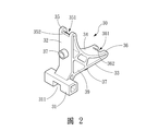
請參閱「圖1」、「圖2」與「圖3」所示,本發明為一種束板固定裝置,用於固定至少一層板10,其包含一束帶20與一主框體30,其中該束帶20具有一束口21與一單向穿過該束口21而止退的止退帶22 。Please refer to "Figure 1", "Figure 2" and "Figure 3". The present invention is a beam plate fixing device for fixing at least one layer of
而該主框體30具有一中心柱31、一第一主固定邊32、一第二主固定邊33與一主相連邊34,其中該主相連邊34的兩端分別連接該第一主固定邊32、該第二主固定邊33的一端並分別形成一第一主轉角35、一第二主轉角36,該第一主固定邊32、該第二主固定邊33遠離該主相連邊34的另一端分別連接該中心柱31,且該中心柱31、該第一主轉角35、該第二主轉角36分別具有供該止退帶22穿過而卡制該止退帶22的一中心柱凹槽311、一第一主凹槽351與一第二主凹槽361。The
又該中心柱31可以為矩形狀,且該中心柱31的寬度可以對應該層板10的寬度;該第一主固定邊32與該第二主固定邊33可以分別具有至少一固定凸柱37,該至少一固定凸柱37供卡入該至少一層板10,在實際實施上,該層板10具有一對應該固定凸柱37的固定凹洞11與一供該束帶20穿過的穿孔12。另該第一主固定邊32可以垂直該第二主固定邊33,並該第一主轉角35可以分別於兩側各設置一銳角斜面352,同樣的該第二主轉角36也可以分別於兩側各具有一銳角斜面362,該銳角斜面352、362可以輔助固定該止退帶22,讓該止退帶22不易脫落。In addition, the
而在第一實施例中,為固定二個該層板10,該層板10為緊鄰該中心柱31與該第一主固定邊32的區域,以及該中心柱31與該第二主固定邊33的區域,藉由讓該固定凸柱37與該固定凹洞11卡合,即可初步固定該層板10與該主框體30的位置,而方便該止退帶22穿過該中心柱凹槽311、該第一主凹槽351、該第二主凹槽361與該穿孔12,最後穿過該束口21即可束緊該主框體30與該層板10,故可以確保該層板10沒有鬆脫的問題。In the first embodiment, to fix two of the
請參閱「圖4」所示,本發明更可以包含一副框體40,該副框體40具有一第一副固定邊41、一第二副固定邊42與一副相連邊43,該副相連邊43的兩端分別連接該第一副固定邊41、該第二副固定邊42的一端,並分別形成一第一副轉角44、一第二副轉角45,該第一副固定邊41、該第二副固定邊42遠離該副相連邊43的另一端為相連接,且該第一副轉角44、該第二副轉角45分別具有供該止退帶22穿過而卡制該止退帶22的一第一副凹槽441與一第二副凹槽451。Please refer to "Figure 4", the present invention may further include a
同樣的,該第一副固定邊41與該第二副固定邊42可以分別具有至少一卡入該至少一層板10的固定凸柱46,且該第一副固定邊41可以垂直該第二副固定邊42;並該第一副轉角44可以分別於兩側各設置一銳角斜面442,同樣的該第二副轉角45也可以分別於兩側各具有一銳角斜面452,該銳角斜面442、452可以輔助固定該止退帶22,讓該止退帶22不易脫落。Similarly, the first auxiliary fixed
請參閱「圖5」所示,在第二實施例中,其為使用一個該主框體30、一個該束帶20與一個該副框體40,並固定三個該層板10為例說明,其為先藉由讓該固定凸柱37、46與該固定凹洞11卡合,即可初步固定該層板10、該副框體40與該主框體30的相對位置,接著利用該止退帶22穿過該第一主凹槽351、該第二主凹槽361、該第一副凹槽441、該第二副凹槽451與該穿孔12,最後穿過該束口21而即可束緊該主框體30、該副框體40與該層板10,故可以確保該層板10沒有鬆脫的問題。Please refer to "FIG. 5". In the second embodiment, one
請參閱「圖6」所示,在第三實施例中,其為使用一個該主框體30、一個該束帶20與三個該副框體40,並固定四個該層板10為例說明,同樣先藉由讓該固定凸柱37、46與該固定凹洞11卡合,即可初步固定該層板10、該副框體40與該主框體30的相對位置,接著利用該止退帶22穿過該第一主凹槽351、該第二主凹槽361、該第一副凹槽441、該第二副凹槽451與該穿孔12,最後穿過該束口21而即可束緊該主框體30、該副框體40與該層板10,故可以確保該層板10沒有鬆脫的問題。Please refer to "FIG. 6". In the third embodiment, one
請再參閱「圖2」、「圖4」「圖7」所示,為本發明第四實施例,該主框體30更可以包含一除料孔39,該除料孔39可供一背板50的一定位柱51穿過而卡合;同樣的,該副框體40可以具有一除料孔48,同樣可供該背板50的該定位柱51穿過,因此藉由該定位柱51固定於該除料孔39、48上,即可固定該背板50。Please refer to "FIG. 2", "FIG. 4" and "FIG. 7", which are the fourth embodiment of the present invention. The
綜上所述,本發明具有以下特點:In summary, the present invention has the following characteristics:
一、利用束帶來輔助固定層板,沒有螺絲螺所鬆脫的問題,可滿足使用上的需求。1. The use of straps to assist in fixing the laminate, there is no problem of loosening of screws, which can meet the needs of use.
二、主框體配合副框體使用,可與層板組成不同形式的結構,滿足不同型式櫃體的組裝需求。2. The main frame is used in conjunction with the auxiliary frame, and can be combined with the laminate to form different forms of structure to meet the assembly requirements of different types of cabinets.
三、利用設置銳角斜面的方式,避免束帶滑脫,可以增加結構的穩定性。3. Use the method of setting an acute angle slope to prevent the strap from slipping off, which can increase the stability of the structure.
10:層板 11:固定凹洞 12:穿孔 20:束帶 21:束口 22:止退帶 30:主框體 31:中心柱 311:中心柱凹槽 32:第一主固定邊 33:第二主固定邊 34:主相連邊 35:第一主轉角 351:第一主凹槽 352:銳角斜面 36:第二主轉角 361:第二主凹槽 362:銳角斜面 37:固定凸柱 39:除料孔 40:副框體 41:第一副固定邊 42:第二副固定邊 43:副相連邊 44:第一副轉角 441:第一副凹槽 442:銳角斜面 45:第二副轉角 451:第二副凹槽 452:銳角斜面 46:固定凸柱 48:除料孔 50:背板 51:定位柱10: Shelves 11: fixed cavity 12: Piercing 20: Drawstring 21: beam mouth 22: Stop belt 30: main frame 31: Center column 311: Center column groove 32: The first main fixed side 33: The second main fixed side 34: Main connected edge 35: The first main corner 351: The first main groove 352: Acute Angle Bevel 36: second main corner 361: second main groove 362: Acute Angle Bevel 37: fixed boss 39: cutout hole 40: Sub-frame 41: The first set of fixed sides 42: The second fixed side 43: secondary connected edge 44: The first corner 441: The first groove 442: Acute Angle Bevel 45: second corner 451: second groove 452: Acute Angle Bevel 46: fixed boss 48: cutout hole 50: backplane 51: positioning column
圖1,為本發明第一實施例的主框體與束帶結構示意圖。 圖2,為本發明第一實施例的主框體另一角度結構示意圖。 圖3,為本發明第一實施例的層板固定示意圖。 圖4,為本發明第二實施例圖的副框體結構示意圖。 圖5,為本發明第二實施例的層板固定示意圖。 圖6,為本發明第三實施例的層板固定示意圖。 圖7,為本發明第四實施例的背板固定示意圖。FIG. 1 is a schematic diagram of the structure of the main frame and the straps of the first embodiment of the present invention. FIG. 2 is a schematic structural view of another angle of the main frame of the first embodiment of the present invention. Fig. 3 is a schematic diagram of the fixing of the laminate in the first embodiment of the invention. FIG. 4 is a schematic diagram of the structure of the sub-frame in the second embodiment of the present invention. Fig. 5 is a schematic diagram of fixing the laminate in the second embodiment of the present invention. Fig. 6 is a schematic diagram of the fixing of the laminate in the third embodiment of the invention. Fig. 7 is a schematic diagram of fixing the back plate of the fourth embodiment of the present invention.
10:層板10: Shelves
11:固定凹洞11: fixed cavity
12:穿孔12: Piercing
20:束帶20: Drawstring
21:束口21: beam mouth
22:止退帶22: Stop belt
30:主框體30: main frame
31:中心柱31: Center column
311:中心柱凹槽311: Center column groove
32:第一主固定邊32: The first main fixed side
33:第二主固定邊33: The second main fixed side
34:主相連邊34: Main connected edge
35:第一主轉角35: The first main corner
351:第一主凹槽351: The first main groove
36:第二主轉角36: second main corner
361:第二主凹槽361: second main groove
37:固定凸柱37: fixed boss
39:除料孔39: cutout hole
Claims (10)
Priority Applications (1)
| Application Number | Priority Date | Filing Date | Title |
|---|---|---|---|
| TW108132270A TWI702021B (en) | 2019-09-06 | 2019-09-06 | Beam plate fixing device |
Applications Claiming Priority (1)
| Application Number | Priority Date | Filing Date | Title |
|---|---|---|---|
| TW108132270A TWI702021B (en) | 2019-09-06 | 2019-09-06 | Beam plate fixing device |
Publications (2)
| Publication Number | Publication Date |
|---|---|
| TWI702021B TWI702021B (en) | 2020-08-21 |
| TW202110364A true TW202110364A (en) | 2021-03-16 |
Family
ID=73003115
Family Applications (1)
| Application Number | Title | Priority Date | Filing Date |
|---|---|---|---|
| TW108132270A TWI702021B (en) | 2019-09-06 | 2019-09-06 | Beam plate fixing device |
Country Status (1)
| Country | Link |
|---|---|
| TW (1) | TWI702021B (en) |
Cited By (1)
| Publication number | Priority date | Publication date | Assignee | Title |
|---|---|---|---|---|
| TWI800178B (en) * | 2021-12-23 | 2023-04-21 | 張文聰 | Variety of DIY combination frame structure |
Family Cites Families (11)
| Publication number | Priority date | Publication date | Assignee | Title |
|---|---|---|---|---|
| TW561852U (en) * | 2001-10-30 | 2003-11-11 | Hsin Ind Co Ltd Y | Rapid assembly joint set for side plates of closet frame |
| TW506596U (en) * | 2001-12-21 | 2002-10-11 | Leger Furniture Co Ltd | Easily-assembled type support frame structure |
| TWM245847U (en) * | 2003-08-29 | 2004-10-11 | Kuen-Lung Jeng | Structure of corner assembly component for furniture |
| JP4222342B2 (en) * | 2005-06-23 | 2009-02-12 | パナソニック電工株式会社 | Shelf plate mounting device |
| TWM297665U (en) * | 2006-03-27 | 2006-09-21 | Jiun-Shiung Wu | Improved fixture structure of storage rack board |
| TWM424849U (en) * | 2011-09-30 | 2012-03-21 | Leer Technology Co Ltd K | Positioning member capable of positioning shelf plate on rack |
| ITMI20130158A1 (en) * | 2013-02-05 | 2014-08-06 | Salice Arturo Spa | DEVICE FOR ADJUSTABLE FIXING OF A FRONT PANEL OF A DRAWER OR SIMILAR, AND DRAWER PROVIDED WITH THE SAME FIXING DEVICES |
| CN203280089U (en) * | 2013-05-14 | 2013-11-13 | 平湖台丽办公自动化设备有限公司 | Supporting plate fixing block |
| CN103735060B (en) * | 2013-12-26 | 2015-12-16 | 宁波虎王保险箱有限公司 | Adjustable interlayer plate fixture |
| TWM544246U (en) * | 2016-12-15 | 2017-07-01 | Chuan-Ching Yeh | Coupling structure of metal netting shelf-board and frame piece for shelf |
| TWM593198U (en) * | 2019-09-06 | 2020-04-11 | 國立臺中科技大學 | Shelf fixing element |
-
2019
- 2019-09-06 TW TW108132270A patent/TWI702021B/en active
Cited By (1)
| Publication number | Priority date | Publication date | Assignee | Title |
|---|---|---|---|---|
| TWI800178B (en) * | 2021-12-23 | 2023-04-21 | 張文聰 | Variety of DIY combination frame structure |
Also Published As
| Publication number | Publication date |
|---|---|
| TWI702021B (en) | 2020-08-21 |
Similar Documents
| Publication | Publication Date | Title |
|---|---|---|
| US20180335062A1 (en) | Panel clamp apparatus and system | |
| US20100205888A1 (en) | Connector for panels or panel-like components | |
| TWI702021B (en) | Beam plate fixing device | |
| WO2016161966A1 (en) | Connector and material module for connection using same | |
| US10215209B2 (en) | Aluminum cabinet | |
| US20090110474A1 (en) | Connector for panels or panel-like components | |
| WO2017201769A1 (en) | Combination furniture | |
| TWM593198U (en) | Shelf fixing element | |
| WO2020062895A1 (en) | Furniture product assembly connecting member | |
| US20190078598A1 (en) | Panel lock construct | |
| JP2023044433A (en) | Joint member, assembly frame, assembly kit, and joint member set | |
| US11118617B1 (en) | Table leg attachment | |
| US20140331904A1 (en) | Production bench | |
| TWI737281B (en) | Computer and support thereof | |
| CN211099157U (en) | Experiment table convenient to assemble | |
| CN216519089U (en) | a hanging block | |
| TWI734519B (en) | Flat-pack furniture and composite post thereof | |
| CN212106479U (en) | A positioning buckle applied to honeycomb board | |
| CN216519022U (en) | Plate connecting assembly and cabinet body | |
| CN221291673U (en) | Assembled multiply wood | |
| CN220513424U (en) | Combined plate connecting structural member | |
| JP5757672B2 (en) | Frame connection structure for stage installation | |
| CN210960939U (en) | Cabinet capable of being installed quickly | |
| KR101683236B1 (en) | Combine device for plural of polygon box | |
| CN213488266U (en) | Laminate installation assembly |