TW202017542A - Intraocular gas injector - Google Patents
Intraocular gas injector Download PDFInfo
- Publication number
- TW202017542A TW202017542A TW108137476A TW108137476A TW202017542A TW 202017542 A TW202017542 A TW 202017542A TW 108137476 A TW108137476 A TW 108137476A TW 108137476 A TW108137476 A TW 108137476A TW 202017542 A TW202017542 A TW 202017542A
- Authority
- TW
- Taiwan
- Prior art keywords
- chamber
- filter
- gas
- plunger
- palm
- Prior art date
Links
Images


Classifications
-
- A—HUMAN NECESSITIES
- A61—MEDICAL OR VETERINARY SCIENCE; HYGIENE
- A61F—FILTERS IMPLANTABLE INTO BLOOD VESSELS; PROSTHESES; DEVICES PROVIDING PATENCY TO, OR PREVENTING COLLAPSING OF, TUBULAR STRUCTURES OF THE BODY, e.g. STENTS; ORTHOPAEDIC, NURSING OR CONTRACEPTIVE DEVICES; FOMENTATION; TREATMENT OR PROTECTION OF EYES OR EARS; BANDAGES, DRESSINGS OR ABSORBENT PADS; FIRST-AID KITS
- A61F9/00—Methods or devices for treatment of the eyes; Devices for putting in contact-lenses; Devices to correct squinting; Apparatus to guide the blind; Protective devices for the eyes, carried on the body or in the hand
- A61F9/0008—Introducing ophthalmic products into the ocular cavity or retaining products therein
-
- A—HUMAN NECESSITIES
- A61—MEDICAL OR VETERINARY SCIENCE; HYGIENE
- A61F—FILTERS IMPLANTABLE INTO BLOOD VESSELS; PROSTHESES; DEVICES PROVIDING PATENCY TO, OR PREVENTING COLLAPSING OF, TUBULAR STRUCTURES OF THE BODY, e.g. STENTS; ORTHOPAEDIC, NURSING OR CONTRACEPTIVE DEVICES; FOMENTATION; TREATMENT OR PROTECTION OF EYES OR EARS; BANDAGES, DRESSINGS OR ABSORBENT PADS; FIRST-AID KITS
- A61F9/00—Methods or devices for treatment of the eyes; Devices for putting in contact-lenses; Devices to correct squinting; Apparatus to guide the blind; Protective devices for the eyes, carried on the body or in the hand
- A61F9/007—Methods or devices for eye surgery
-
- A—HUMAN NECESSITIES
- A61—MEDICAL OR VETERINARY SCIENCE; HYGIENE
- A61D—VETERINARY INSTRUMENTS, IMPLEMENTS, TOOLS, OR METHODS
- A61D1/00—Surgical instruments for veterinary use
-
- A—HUMAN NECESSITIES
- A61—MEDICAL OR VETERINARY SCIENCE; HYGIENE
- A61F—FILTERS IMPLANTABLE INTO BLOOD VESSELS; PROSTHESES; DEVICES PROVIDING PATENCY TO, OR PREVENTING COLLAPSING OF, TUBULAR STRUCTURES OF THE BODY, e.g. STENTS; ORTHOPAEDIC, NURSING OR CONTRACEPTIVE DEVICES; FOMENTATION; TREATMENT OR PROTECTION OF EYES OR EARS; BANDAGES, DRESSINGS OR ABSORBENT PADS; FIRST-AID KITS
- A61F9/00—Methods or devices for treatment of the eyes; Devices for putting in contact-lenses; Devices to correct squinting; Apparatus to guide the blind; Protective devices for the eyes, carried on the body or in the hand
- A61F9/007—Methods or devices for eye surgery
- A61F9/00736—Instruments for removal of intra-ocular material or intra-ocular injection, e.g. cataract instruments
-
- A—HUMAN NECESSITIES
- A61—MEDICAL OR VETERINARY SCIENCE; HYGIENE
- A61M—DEVICES FOR INTRODUCING MEDIA INTO, OR ONTO, THE BODY; DEVICES FOR TRANSDUCING BODY MEDIA OR FOR TAKING MEDIA FROM THE BODY; DEVICES FOR PRODUCING OR ENDING SLEEP OR STUPOR
- A61M5/00—Devices for bringing media into the body in a subcutaneous, intra-vascular or intramuscular way; Accessories therefor, e.g. filling or cleaning devices, arm-rests
- A61M5/178—Syringes
- A61M5/19—Syringes having more than one chamber, e.g. including a manifold coupling two parallelly aligned syringes through separate channels to a common discharge assembly
-
- A—HUMAN NECESSITIES
- A61—MEDICAL OR VETERINARY SCIENCE; HYGIENE
- A61M—DEVICES FOR INTRODUCING MEDIA INTO, OR ONTO, THE BODY; DEVICES FOR TRANSDUCING BODY MEDIA OR FOR TAKING MEDIA FROM THE BODY; DEVICES FOR PRODUCING OR ENDING SLEEP OR STUPOR
- A61M5/00—Devices for bringing media into the body in a subcutaneous, intra-vascular or intramuscular way; Accessories therefor, e.g. filling or cleaning devices, arm-rests
- A61M5/178—Syringes
- A61M5/28—Syringe ampoules or carpules, i.e. ampoules or carpules provided with a needle
- A61M5/284—Syringe ampoules or carpules, i.e. ampoules or carpules provided with a needle comprising means for injection of two or more media, e.g. by mixing
-
- A—HUMAN NECESSITIES
- A61—MEDICAL OR VETERINARY SCIENCE; HYGIENE
- A61M—DEVICES FOR INTRODUCING MEDIA INTO, OR ONTO, THE BODY; DEVICES FOR TRANSDUCING BODY MEDIA OR FOR TAKING MEDIA FROM THE BODY; DEVICES FOR PRODUCING OR ENDING SLEEP OR STUPOR
- A61M5/00—Devices for bringing media into the body in a subcutaneous, intra-vascular or intramuscular way; Accessories therefor, e.g. filling or cleaning devices, arm-rests
- A61M5/178—Syringes
- A61M5/28—Syringe ampoules or carpules, i.e. ampoules or carpules provided with a needle
- A61M5/285—Syringe ampoules or carpules, i.e. ampoules or carpules provided with a needle with sealing means to be broken or opened
- A61M5/288—Syringe ampoules or carpules, i.e. ampoules or carpules provided with a needle with sealing means to be broken or opened by piercing without internal pressure increase
-
- A—HUMAN NECESSITIES
- A61—MEDICAL OR VETERINARY SCIENCE; HYGIENE
- A61M—DEVICES FOR INTRODUCING MEDIA INTO, OR ONTO, THE BODY; DEVICES FOR TRANSDUCING BODY MEDIA OR FOR TAKING MEDIA FROM THE BODY; DEVICES FOR PRODUCING OR ENDING SLEEP OR STUPOR
- A61M5/00—Devices for bringing media into the body in a subcutaneous, intra-vascular or intramuscular way; Accessories therefor, e.g. filling or cleaning devices, arm-rests
- A61M5/178—Syringes
- A61M5/31—Details
- A61M5/3145—Filters incorporated in syringes
-
- A—HUMAN NECESSITIES
- A61—MEDICAL OR VETERINARY SCIENCE; HYGIENE
- A61M—DEVICES FOR INTRODUCING MEDIA INTO, OR ONTO, THE BODY; DEVICES FOR TRANSDUCING BODY MEDIA OR FOR TAKING MEDIA FROM THE BODY; DEVICES FOR PRODUCING OR ENDING SLEEP OR STUPOR
- A61M5/00—Devices for bringing media into the body in a subcutaneous, intra-vascular or intramuscular way; Accessories therefor, e.g. filling or cleaning devices, arm-rests
- A61M5/178—Syringes
- A61M5/31—Details
- A61M5/315—Pistons; Piston-rods; Guiding, blocking or restricting the movement of the rod or piston; Appliances on the rod for facilitating dosing ; Dosing mechanisms
- A61M5/31533—Dosing mechanisms, i.e. setting a dose
- A61M5/31535—Means improving security or handling thereof, e.g. blocking means, means preventing insufficient dosing, means allowing correction of overset dose
- A61M5/31536—Blocking means to immobilize a selected dose, e.g. to administer equal doses
-
- A—HUMAN NECESSITIES
- A61—MEDICAL OR VETERINARY SCIENCE; HYGIENE
- A61M—DEVICES FOR INTRODUCING MEDIA INTO, OR ONTO, THE BODY; DEVICES FOR TRANSDUCING BODY MEDIA OR FOR TAKING MEDIA FROM THE BODY; DEVICES FOR PRODUCING OR ENDING SLEEP OR STUPOR
- A61M5/00—Devices for bringing media into the body in a subcutaneous, intra-vascular or intramuscular way; Accessories therefor, e.g. filling or cleaning devices, arm-rests
- A61M5/178—Syringes
- A61M5/31—Details
- A61M5/315—Pistons; Piston-rods; Guiding, blocking or restricting the movement of the rod or piston; Appliances on the rod for facilitating dosing ; Dosing mechanisms
- A61M5/31596—Pistons; Piston-rods; Guiding, blocking or restricting the movement of the rod or piston; Appliances on the rod for facilitating dosing ; Dosing mechanisms comprising means for injection of two or more media, e.g. by mixing
-
- A—HUMAN NECESSITIES
- A61—MEDICAL OR VETERINARY SCIENCE; HYGIENE
- A61D—VETERINARY INSTRUMENTS, IMPLEMENTS, TOOLS, OR METHODS
- A61D7/00—Devices or methods for introducing solid, liquid, or gaseous remedies or other materials into or onto the bodies of animals
-
- A—HUMAN NECESSITIES
- A61—MEDICAL OR VETERINARY SCIENCE; HYGIENE
- A61M—DEVICES FOR INTRODUCING MEDIA INTO, OR ONTO, THE BODY; DEVICES FOR TRANSDUCING BODY MEDIA OR FOR TAKING MEDIA FROM THE BODY; DEVICES FOR PRODUCING OR ENDING SLEEP OR STUPOR
- A61M5/00—Devices for bringing media into the body in a subcutaneous, intra-vascular or intramuscular way; Accessories therefor, e.g. filling or cleaning devices, arm-rests
- A61M5/178—Syringes
- A61M5/31—Details
- A61M2005/3128—Incorporating one-way valves, e.g. pressure-relief or non-return valves
-
- A—HUMAN NECESSITIES
- A61—MEDICAL OR VETERINARY SCIENCE; HYGIENE
- A61M—DEVICES FOR INTRODUCING MEDIA INTO, OR ONTO, THE BODY; DEVICES FOR TRANSDUCING BODY MEDIA OR FOR TAKING MEDIA FROM THE BODY; DEVICES FOR PRODUCING OR ENDING SLEEP OR STUPOR
- A61M2202/00—Special media to be introduced, removed or treated
- A61M2202/02—Gases
-
- A—HUMAN NECESSITIES
- A61—MEDICAL OR VETERINARY SCIENCE; HYGIENE
- A61M—DEVICES FOR INTRODUCING MEDIA INTO, OR ONTO, THE BODY; DEVICES FOR TRANSDUCING BODY MEDIA OR FOR TAKING MEDIA FROM THE BODY; DEVICES FOR PRODUCING OR ENDING SLEEP OR STUPOR
- A61M2210/00—Anatomical parts of the body
- A61M2210/06—Head
- A61M2210/0612—Eyes
-
- A—HUMAN NECESSITIES
- A61—MEDICAL OR VETERINARY SCIENCE; HYGIENE
- A61M—DEVICES FOR INTRODUCING MEDIA INTO, OR ONTO, THE BODY; DEVICES FOR TRANSDUCING BODY MEDIA OR FOR TAKING MEDIA FROM THE BODY; DEVICES FOR PRODUCING OR ENDING SLEEP OR STUPOR
- A61M5/00—Devices for bringing media into the body in a subcutaneous, intra-vascular or intramuscular way; Accessories therefor, e.g. filling or cleaning devices, arm-rests
- A61M5/14—Infusion devices, e.g. infusing by gravity; Blood infusion; Accessories therefor
- A61M5/142—Pressure infusion, e.g. using pumps
- A61M5/145—Pressure infusion, e.g. using pumps using pressurised reservoirs, e.g. pressurised by means of pistons
-
- A—HUMAN NECESSITIES
- A61—MEDICAL OR VETERINARY SCIENCE; HYGIENE
- A61M—DEVICES FOR INTRODUCING MEDIA INTO, OR ONTO, THE BODY; DEVICES FOR TRANSDUCING BODY MEDIA OR FOR TAKING MEDIA FROM THE BODY; DEVICES FOR PRODUCING OR ENDING SLEEP OR STUPOR
- A61M5/00—Devices for bringing media into the body in a subcutaneous, intra-vascular or intramuscular way; Accessories therefor, e.g. filling or cleaning devices, arm-rests
- A61M5/178—Syringes
- A61M5/31—Details
- A61M5/315—Pistons; Piston-rods; Guiding, blocking or restricting the movement of the rod or piston; Appliances on the rod for facilitating dosing ; Dosing mechanisms
- A61M5/31565—Administration mechanisms, i.e. constructional features, modes of administering a dose
- A61M5/31576—Constructional features or modes of drive mechanisms for piston rods
- A61M5/31578—Constructional features or modes of drive mechanisms for piston rods based on axial translation, i.e. components directly operatively associated and axially moved with plunger rod
- A61M5/3158—Constructional features or modes of drive mechanisms for piston rods based on axial translation, i.e. components directly operatively associated and axially moved with plunger rod performed by axially moving actuator operated by user, e.g. an injection button
Landscapes
- Health & Medical Sciences (AREA)
- Veterinary Medicine (AREA)
- Life Sciences & Earth Sciences (AREA)
- Animal Behavior & Ethology (AREA)
- Engineering & Computer Science (AREA)
- Public Health (AREA)
- General Health & Medical Sciences (AREA)
- Heart & Thoracic Surgery (AREA)
- Vascular Medicine (AREA)
- Biomedical Technology (AREA)
- Anesthesiology (AREA)
- Hematology (AREA)
- Ophthalmology & Optometry (AREA)
- Surgery (AREA)
- Nuclear Medicine, Radiotherapy & Molecular Imaging (AREA)
- Wood Science & Technology (AREA)
- Zoology (AREA)
- Infusion, Injection, And Reservoir Apparatuses (AREA)
Abstract
Description
本文揭露的發明總體上係關於用於將氣體注入動物的眼睛中的裝置及方法。The invention disclosed herein relates generally to devices and methods for injecting gas into the eyes of animals.
手術過程可能需要將氣體或其他流體注入目的地區域以用於治療某些損傷、病症和疾病。在治療比如黃斑裂孔、視網膜撕裂和脫離等眼部狀況時,手術過程的一部分可能包括將氣體或其他流體注入眼睛內。The surgical procedure may require the injection of gas or other fluids into the destination area for the treatment of certain injuries, conditions and diseases. When treating eye conditions such as macular holes, retinal tears, and detachment, part of the surgical procedure may include injection of gas or other fluids into the eye.
例如,視網膜脫離係涉及視網膜與視網膜色素上皮(RPE)分離的眼部病症,視網膜色素上皮係將視網膜固定就位之組織。視網膜脫離可能是由於視網膜撕裂、在視網膜上牽拉、或使得流體積聚在視網膜下腔中的炎症而發生,由此導致視網膜開始與支撐RPE組織分離。這種病症也可能由於玻璃體後脫離(PVD)、增生性糖尿病性視網膜病(PDR)、損傷、或纖維組織或脈管組織的新生血管生成而發生,導致視網膜從RPE上脫離。如果不立即治療,這種狀況可能會導致部分視力喪失,並且甚至可能失明。For example, the retinal detachment system involves eye disorders where the retina is separated from the retinal pigment epithelium (RPE). The retinal pigment epithelium is the tissue that holds the retina in place. Retinal detachment may occur due to tearing of the retina, pulling on the retina, or inflammation that causes fluid to accumulate in the subretinal space, thereby causing the retina to begin to separate from the supporting RPE tissue. This condition may also occur due to posterior vitreous detachment (PVD), proliferative diabetic retinopathy (PDR), injury, or neovascularization of fibrous tissue or vascular tissue, resulting in detachment of the retina from the RPE. If left untreated, this condition may cause partial vision loss and may even be blind.
用於並不複雜的視網膜脫離的治療方法可以包括比如充氣性視網膜固定術、雷射光凝術或低溫固定術等非手術技術。更複雜的視網膜脫離需要手術介入。由於可能潛在地導致失明的感染風險,在無菌條件下進行此類手術以便顯著降低感染的可能性。手術方法包括:玻璃體切除術,即去除玻璃體液;在牽引性視網膜脫離的情況下切開並去除膜;以及在另外有視網膜撕裂的情況下進行光凝或低溫固定術。在這樣的手術過程之後,可以使用眼內氣體填塞物以使視網膜組織與RPE保持接觸,這樣使得視網膜在手術過程之後的癒合過程期間保持附接。Treatment methods for uncomplicated retinal detachment may include non-surgical techniques such as inflatable retinal fixation, laser photocoagulation, or cryopreservation. More complicated retinal detachment requires surgical intervention. Because of the risk of infection that can potentially lead to blindness, such surgery is performed under sterile conditions to significantly reduce the likelihood of infection. Surgical methods include: vitrectomy, that is, removal of vitreous humor; incision and removal of the membrane in the case of traction retinal detachment; and photocoagulation or hypothermia in the case of additional retinal tears. After such a surgical procedure, an intraocular gas tampon can be used to keep the retinal tissue in contact with the RPE, so that the retina remains attached during the healing process after the surgical procedure.
由於眼內壓必須在癒合過程期間保持相對恒定,因此所選擇的氣體通常是在恒定壓力(等壓過程)下膨脹的氣體。這樣,眼內氣體填塞物可以是空氣與比如六氟化硫(SF6 )、六氟乙烷(C2 F6 )或八氟丙烷(C3 F8 )等可膨脹氣體混合的氣泡。眼內氣體填塞物隨時間而溶解,取決於所用的氣體和濃度。例如,六氟化硫在以大約20%的濃度與空氣混合時在1-2週內溶解,六氟乙烷在以大約16%的濃度與空氣混合時在大約4-5週內溶解,而八氟丙烷在以大約12%的濃度與空氣混合時在大約6-8週內溶解。改變該等氣體的濃度影響了持續時間。Since the intraocular pressure must remain relatively constant during the healing process, the gas selected is usually a gas that expands at a constant pressure (isobaric process). In this way, the intragastric gas packing may be air bubbles mixed with expandable gas such as sulfur hexafluoride (SF 6 ), hexafluoroethane (C 2 F 6 ) or octafluoropropane (C 3 F 8 ). The gas packing in the eye dissolves with time, depending on the gas and concentration used. For example, sulfur hexafluoride dissolves within 1-2 weeks when mixed with air at a concentration of approximately 20%, and hexafluoroethane dissolves within approximately 4-5 weeks when mixed with air at a concentration of approximately 16%, and Octafluoropropane dissolves in about 6-8 weeks when mixed with air at a concentration of about 12%. Changing the concentration of these gases affects the duration.
目前的做法涉及使用容納在單獨的多劑量加壓容器中的氣體,然後將氣體轉移到注射器中以用於與空氣混合並注入患者的眼睛。因此,在手術過程期間,需要多個非無菌步驟和無菌步驟,以便用所需濃度的氣體和空氣來填充注射器。通常由非無菌手術室巡迴護士以及無菌區中的輔助外科醫生的無菌擦洗技工來執行該等非無菌步驟和無菌步驟。在第一個非無菌性步驟期間,巡迴護士藉由將與氣體容器連接的壓力調節器設置在適當的壓力下來準備非無菌性可重複使用的氣體容器。在第二個步驟期間,擦洗技工藉由將旋塞閥、過濾器和管件串聯連接到注射器上來準備無菌注射器。在第三個步驟期間,將管件連接到氣體容器。擦洗技工將無菌管件的自由端小心地穿過不可見的無菌屏障遞給等待的非無菌巡迴護士。非無菌巡迴護士收到管件並仔細確保他/她不會使擦洗技工或任何其他無菌表面受到污染;並且將管件連接到氣體容器上的調節器。在第四個步驟期間,隨後用來自容器的氣體來填充注射器。擦洗技工和巡迴護士合作打開壓力容器閥以通過所連接的管件、過濾器、旋塞閥將氣體釋放到注射器中。所釋放的氣體的壓力足以沿注射筒的長度推動注射器柱塞並且因此用氣體填充注射器。擦洗技工確保氣體不會將柱塞推出注射筒的開放端,並且在注射器接近完全填充狀況時通知巡迴護士關閉氣體容器閥。在第五個步驟期間,隨後清除注射器中的所有空氣和氣體,以便確保已經清除了在用氣體進行填充之前可能已經存在於注射器、旋塞閥、過濾器和管件中的絕大部分空氣。擦洗技工轉動旋塞閥以提供某種手段將注射器中的空氣和氣體釋放到大氣中,按壓注射器柱塞,並且清空注射器中的所有內容物。然後,擦洗技工沿相反方向轉動旋塞閥,從而使連接路徑返回到管件和氣體容器。Current practice involves using the gas contained in a separate multi-dose pressurized container, and then transferring the gas to a syringe for mixing with air and injecting it into the patient's eye. Therefore, during the surgical procedure, multiple non-sterile steps and sterile steps are required in order to fill the syringe with the required concentration of gas and air. These non-sterile steps and aseptic steps are usually performed by a sterile nurse in a non-sterile operating room and a sterile scrub technician assisting the surgeon in the sterile area. During the first non-sterile step, the itinerant nurse prepares the non-sterile reusable gas container by setting the pressure regulator connected to the gas container at an appropriate pressure. During the second step, the scrubber prepares a sterile syringe by connecting the stopcock, filter, and tubing to the syringe in series. During the third step, the tubing is connected to the gas container. The scrubber carefully passed the free end of the sterile tubing through the invisible sterile barrier to the waiting non-sterile touring nurse. The non-sterile circuit nurse receives the tube and carefully ensures that he/she will not contaminate the scrubber or any other sterile surface; and connects the tube to the regulator on the gas container. During the fourth step, the syringe is then filled with gas from the container. The scrubber and tour nurse cooperated to open the pressure vessel valve to release gas into the syringe through the connected tubing, filter, and stopcock. The pressure of the released gas is sufficient to push the syringe plunger along the length of the syringe and thus fill the syringe with gas. The scrubber ensures that the gas does not push the plunger out of the open end of the syringe, and notifies the circuit nurse to close the gas container valve when the syringe is close to full filling. During the fifth step, all air and gas in the syringe are subsequently purged to ensure that most of the air that may have been present in the syringe, stopcock, filter and tubing before filling with gas has been purged. The scrubber rotates the stopcock to provide some means to release the air and gas from the syringe into the atmosphere, press the syringe plunger, and empty all the contents of the syringe. The scrubber then turns the stopcock in the opposite direction, returning the connection path to the pipe and gas container.
步驟四和步驟五重複了若干次,以進一步減少最初在注射器、旋塞閥、過濾器和管件中的空氣量;沖洗掉注射器、旋塞閥、過濾器和管件中的大部分空氣,並且清除系統的空氣。在第六個步驟期間,隨後用來自容器的氣體重新填充注射器。擦洗技工將管件從過濾器上拆下,並且通知巡迴護士小心取出管件,從而將管件從無菌區移走。在第七個步驟期間,擦洗技工不會排出注射器的所有內容物使柱塞停止,使得僅在注射器中保留測量體積的氣體。例如,可以排出氣體,使得注射器內僅保留12 mL。在第八個步驟期間,擦洗技工將用過的過濾器替換為新的無菌過濾器,並且將過濾後的室內空氣吸入注射器,直到注射器中的總的空氣/氣體混合物處於所需氣體濃度的適當體積。Steps 4 and 5 were repeated several times to further reduce the amount of air initially in the syringe, stopcock, filter, and tube; flush out most of the air in the syringe, stopcock, filter, and tube, and clear the system air. During the sixth step, the syringe is then refilled with gas from the container. The scrubber removes the tube from the filter, and informs the circuit nurse to carefully remove the tube to remove the tube from the sterile area. During the seventh step, the scrubber will not expel all the contents of the syringe to stop the plunger so that only the measured volume of gas remains in the syringe. For example, the gas can be vented so that only 12 mL remains in the syringe. During the eighth step, the scrubber replaces the used filter with a new sterile filter and draws the filtered room air into the syringe until the total air/gas mixture in the syringe is at the appropriate gas concentration volume.
例如,可以將大氣空氣吸入注射器,使得空氣和氣體的總體積為60 mL,因此達到20%的濃度。由於加壓容器係非無菌性的、而注射器和手術區域係無菌的,因此完成上述步驟必須由非無菌區中的至少一方(通常是巡迴護士)、無菌區中的第二方(通常是擦洗技工)來執行,並且需要兩方之間的合作和溝通。For example, atmospheric air can be drawn into the syringe so that the total volume of air and gas is 60 mL, thus reaching a concentration of 20%. Since the pressurized container is non-sterile and the syringe and surgical area are sterile, at least one of the non-sterile areas (usually a traveling nurse) and the second side of the sterile area (usually scrubbing) must be used to complete the above steps Technicians), and requires cooperation and communication between the two parties.
這個過程需要一組複雜的步驟,這樣可能會增加發生錯誤的可能性。該等步驟中的一個步驟的錯誤可能導致使用不正確的氣體濃度,這樣可能導致壓力升高或視網膜填塞持續時間縮短,由此可能致使缺血或復位手術失敗,這兩種情況都可能導致失明。另外,當前的做法導致大量浪費的氣體,這樣既昂貴又對環境有害。因此,對此類氣體、尤其是容納多於一劑的加壓容器中的氣體的處理在處理不當的情況下可能存在對於操作者的潛在危險。正因如此,一些國家甚至可能禁止將該等加壓容器存放在手術室中。This process requires a complex set of steps, which may increase the possibility of errors. An error in one of these steps may result in the use of incorrect gas concentrations, which may result in increased pressure or a shorter duration of retinal packing, which may lead to failure of ischemia or reduction surgery, both of which may cause blindness . In addition, current practices result in large amounts of wasted gas, which is both expensive and harmful to the environment. Therefore, the handling of such gases, especially those in pressurized containers containing more than one dose, may present a potential danger to the operator if not handled properly. Because of this, some countries may even prohibit the storage of such pressurized containers in the operating room.
儘管已經有一些方法改善了當前的過程,比如授予Lambome等人的美國專利案號6,866,142,能夠放置在無菌區中的單劑量容器以及允許填充和清除氣體的Alcon® Constellation®系統,但是該等方法已經不足以解決所有潛在的問題。在美國專利案號8,986,242中揭露了另一種方法,其中注射器設備包括體積限制機構中的可膨脹氣體的內部加壓罐。在使用中,將體積限制機構設定為可膨脹氣體的體積對應於氣體填塞物的最終所需濃度,該氣體填塞物可以包括可膨脹氣體和空氣。將可膨脹氣體釋放到注射器的腔室中,直到注射器的柱塞碰撞到體積限制機構結構,並且將剩餘的可膨脹氣體排放到大氣中。然後將過濾器附接到注射器機構的出口,並且將大氣空氣通過過濾器吸入注射器的腔室中,以便產生所需濃度的可膨脹氣體和空氣的混合物以用於稍後注入。Although there are methods that improve the current process, such as US Patent No. 6,866,142 to Lambome et al., single-dose containers that can be placed in a sterile area and Alcon® Constellation® systems that allow filling and purging of gases, these methods It is not enough to solve all potential problems. Another method is disclosed in US Patent No. 8,986,242, where the syringe device includes an internal pressurized tank of expandable gas in a volume limiting mechanism. In use, the volume limiting mechanism is set so that the volume of the expandable gas corresponds to the final desired concentration of the gas packing, which may include expandable gas and air. The expandable gas is released into the cavity of the syringe until the plunger of the syringe collides with the volume restricting mechanism structure, and the remaining expandable gas is discharged into the atmosphere. The filter is then attached to the outlet of the syringe mechanism, and atmospheric air is drawn through the filter into the cavity of the syringe to produce a mixture of expandable gas and air at the desired concentration for later injection.
本文揭露的發明中的至少一個發明的一方面包括以下實現:一種眼內氣體注入器裝置,可以按減少或消除使用者所需的操作並且可以進一步減少潛在污染源的方式進行組裝和包裝。例如,如上所述,關於美國專利案號8,986,242中揭露的裝置的使用,將可膨脹氣體供應到注射器裝置的內部混合腔室中,其中一些過量的可膨脹氣體通過注射器的出口排出。此後,將過濾器附接到注射器的出口,並且將大氣空氣通過過濾器吸入混合腔室。An aspect of at least one of the inventions disclosed herein includes the realization that an intraocular gas injector device can be assembled and packaged in a manner that reduces or eliminates operations required by the user and can further reduce potential sources of contamination. For example, as described above, regarding the use of the device disclosed in US Patent No. 8,986,242, expandable gas is supplied into the internal mixing chamber of the syringe device, and some of the excess expandable gas is discharged through the outlet of the syringe. Thereafter, the filter is attached to the outlet of the syringe, and atmospheric air is drawn into the mixing chamber through the filter.
本文揭露的發明中的至少一個發明的一方面包括以下實現:一種眼內氣體注入裝置,可以包括注射器主體、治療性氣體源以及過濾器,該過濾器例如在通過出口排出過量治療性氣體之前預先附接到注射器的出口。在一些實施方式中,可以將預先附接有過濾器的氣體注入裝置包裝在無菌容器中以用於手術過程。這樣,使用者可以在整個氣體混合過程中打開無菌容器、取出眼內氣體注入裝置並在過濾器就位的情況下操作眼內氣體注入裝置。例如,在預先附接過濾器的情況下,使用者可以將可膨脹氣體提供到注射器的混合腔室中,用可膨脹氣體或其他選擇的氣體至少部分地填充混合腔室,並且在一些使用模式下允許過量的膨脹性氣體通過注射器主體的出口從混合腔室中排出並且隨後通過過濾器排到大氣中。在這樣的排放過量可膨脹氣體期間,對可膨脹氣體進行過濾將不會具有任何已知的、實質性的直接有益效果。然而,以藉由在排出過量可膨脹氣體期間將過濾器放置就位的模式使用眼內氣體注入器,降低了使裝置內的多個不同的空間體積(包括注射器的柱塞與過濾裝置的過濾膜之間的空間)受到污染的風險。進一步地,一旦過量可膨脹氣體排出完成,使用者便可以將大氣空氣通過過濾器吸入混合腔室,而無需朝向大氣打開中間體積空間。因此,過濾膜與注射器的柱塞之間的中間體積空間對於大氣保持封閉,僅接收已經通過過濾裝置過濾的大氣空氣。One aspect of at least one of the inventions disclosed herein includes the realization that an intraocular gas injection device may include a syringe body, a source of therapeutic gas, and a filter, for example, before discharging excess therapeutic gas through an outlet Attach to the outlet of the syringe. In some embodiments, a gas injection device with a filter attached in advance may be packaged in a sterile container for use in surgical procedures. In this way, the user can open the sterile container during the entire gas mixing process, take out the intraocular gas injection device and operate the intraocular gas injection device with the filter in place. For example, in the case of a pre-attached filter, the user may provide expandable gas into the mixing chamber of the syringe, at least partially fill the mixing chamber with expandable gas or other selected gas, and in some modes of use The lower part allows excess inflation gas to be discharged from the mixing chamber through the outlet of the syringe body and then to the atmosphere through the filter. During such discharge of excess expandable gas, filtering the expandable gas will not have any known, substantial direct beneficial effects. However, using the intraocular gas injector by placing the filter in place during the discharge of excess expandable gas reduces the volume of multiple different spaces within the device (including the plunger of the syringe and the filtration of the filter device) The space between the membranes) is at risk of contamination. Further, once the excess expandable gas is exhausted, the user can draw atmospheric air into the mixing chamber through the filter without opening the intermediate volume space toward the atmosphere. Therefore, the intermediate volume between the filter membrane and the plunger of the syringe remains closed to the atmosphere and only receives the atmospheric air that has been filtered by the filtering device.
在使用者吸入通過過濾裝置進行過濾的所需量的大氣空氣之後,可以移除過濾裝置,並且可以將所需儀器附接到注射器的出口。例如,在一些實施方式中,使用者可以附接針頭以用於將混合的可膨脹氣體和大氣空氣注入到對視網膜剝離進行治療的動物或患者的眼睛中。在附接這種針頭之後,使用者可以用混合腔室內的混合的可膨脹氣體和大氣空氣來沖洗針頭。因此,在手術使用之前,過濾膜與注射器柱塞之間的空間體積沒有暴露於未經過濾的大氣空氣。After the user inhales the required amount of atmospheric air filtered by the filter device, the filter device can be removed, and the required instrument can be attached to the outlet of the syringe. For example, in some embodiments, a user may attach a needle for injecting a mixed expandable gas and atmospheric air into the eyes of an animal or patient who is treating retinal detachment. After attaching such a needle, the user can flush the needle with the mixed expandable gas and atmospheric air in the mixing chamber. Therefore, the volume of space between the filter membrane and the syringe plunger was not exposed to unfiltered atmospheric air prior to surgical use.
本文揭露的發明中的至少一個發明的另一方面包括以下實現:用固定量的源氣體來填充體積可變的氣體混合器可以導致體積可變的腔室的擴張不足,並且因此不能產生所需濃度的混合氣體。因此,本文揭露的發明中的至少一個發明的一方面包括以下實現:將流量限制裝置設置到安裝到眼內氣體注入裝置的出口上的過濾器的出口上可以提供有益的和/或附加的背壓,該背壓可以有益於更好地確保混合腔室擴張到所需體積的治療性氣體(比如可膨脹氣體)或治療性氣體的組分。Another aspect of at least one of the inventions disclosed herein includes the realization that filling a variable-volume gas mixer with a fixed amount of source gas can result in insufficient expansion of the variable-volume chamber, and therefore cannot produce the desired Concentration of mixed gas. Therefore, one aspect of at least one of the inventions disclosed herein includes the realization that placing the flow restriction device on the outlet of the filter mounted on the outlet of the intraocular gas injection device can provide beneficial and/or additional backing This back pressure can be beneficial to better ensure that the mixing chamber expands to the desired volume of therapeutic gas (such as expandable gas) or components of the therapeutic gas.
本文揭露的發明中的至少一個發明的另一方面包括以下實現:附接到眼內氣體注入器的下游過濾器的出口的流量限制器可以在混合腔室中已經填充治療性氣體後在通過過濾器抽入環境空氣或大氣空氣時產生不期望的較強的流量限制。因此,本文揭露的發明中的至少一個發明的一方面包括以下實現:將可移除的流量限制器設置到眼內氣體注入裝置的過濾器的出口可以提供兩種有益的操作模式;在混合腔室的填充階段期間排出過量治療性氣體時產生所需背壓,從而確保混合腔室完全擴張到所需體積以用於容納所需量的治療性氣體,然後移除流量限制器,使用者可以手動地使混合腔室擴張並且通過過濾器吸入大氣空氣,而不會增加在流量限制器就位的情況下與這樣的操作關聯的難度。因此,本文揭露的發明中的至少一個發明的一方面包括一種眼內氣體注入裝置,其具有下游過濾裝置以及在該過濾裝置的下游端的可移除流量限制器。Another aspect of at least one of the inventions disclosed herein includes the realization that the flow restrictor attached to the outlet of the downstream filter of the intraocular gas injector can pass through the filtration after the therapeutic gas has been filled in the mixing chamber When the device draws in ambient air or atmospheric air, it produces undesirably strong flow restrictions. Therefore, one aspect of at least one of the inventions disclosed herein includes the implementation of: providing a removable flow restrictor to the outlet of the filter of the intraocular gas injection device can provide two beneficial modes of operation; in the mixing chamber During the filling phase of the chamber, excess back-up therapeutic gas is generated to generate the required back pressure, thereby ensuring that the mixing chamber is fully expanded to the required volume for the required amount of therapeutic gas, and then the flow restrictor is removed, and the user can The mixing chamber is manually expanded and atmospheric air is drawn through the filter without increasing the difficulty associated with such operations with the flow restrictor in place. Therefore, an aspect of at least one of the inventions disclosed herein includes an intraocular gas injection device having a downstream filtering device and a removable flow restrictor at the downstream end of the filtering device.
本文揭露的發明中的至少一個發明的另一方面包括以下實現:如果在手術室中將過濾裝置附接到注射器的出口,則有可能有異物或污染物進入過濾裝置的上游端並且因此被容納在設置在過濾膜與柱塞之間的體積中。因此,即使隨後通過過濾器將過量可膨脹氣體排出,這種污染和/或異物也可能被過濾膜捕獲,隨後當通過過濾器在相反方向上吸入大氣空氣時被回吹到混合腔室中。因此,本文揭露的發明中的至少一個發明的一方面包括減少了污染和/或異物進入設置在過濾膜與柱塞之間的體積空間的可能性的操作的配置和方法。Another aspect of at least one of the inventions disclosed herein includes the realization that if the filter device is attached to the outlet of the syringe in the operating room, it is possible that foreign objects or contaminants enter the upstream end of the filter device and are therefore contained In the volume between the filter membrane and the plunger. Therefore, even if the excess expandable gas is subsequently discharged through the filter, such pollution and/or foreign matter may be captured by the filter membrane and then blown back into the mixing chamber when atmospheric air is drawn in through the filter in the opposite direction. Therefore, an aspect of at least one of the inventions disclosed herein includes an operational configuration and method that reduces the possibility of contamination and/or foreign matter entering the volume space provided between the filter membrane and the plunger.
以下詳細描述本質上僅是說明性的,並不旨在限制主題的實施方式或此類實施方式的應用和使用。如本文所用,詞語「示例性的」係指「用作示例、實例或例證」。本文中被描述為示例性的任何實施方式都不一定被解釋為比其他實施方式較佳或有利。此外,並不意圖受到在當前技術領域、背景技術、發明內容或以下詳細描述中提出的任何明示或暗示的理論的約束。The following detailed description is merely illustrative in nature and is not intended to limit the implementation of the subject matter or the application and use of such implementations. As used herein, the word "exemplary" means "used as an example, instance, or illustration." Any embodiment described herein as an example is not necessarily to be construed as better or advantageous than other embodiments. Furthermore, there is no intention to be bound by any expressed or implied theory presented in the current technical field, background, brief summary or the following detailed description.
在以下描述中,某些術語可以僅用於參考目的,並且因此不旨在進行限制。例如,比如「上」、「下」、「上方」和「下方」等術語係指附圖中所參考的方向。比如「近」、「遠」、「前」、「背」、「後」和「側」等術語描述了在一致但任意的參考系內的部件的部分的取向和/或位置,這藉由參考描述所討論的部件的文本和相關附圖而變得清楚。這樣的術語可以包括以上具體提到的詞語、其派生詞以及類似含義的詞語。類似地,術語「第一」、「第二」以及其他這樣的數字術語係指結構。In the following description, certain terms may be used for reference purposes only, and thus are not intended to be limiting. For example, terms such as "upper", "lower", "upper" and "lower" refer to the directions referred to in the drawings. Terms such as "near", "far", "front", "back", "back", and "side" describe the orientation and/or position of parts of parts within a consistent but arbitrary reference frame, by This is made clear with reference to the text and related drawings describing the components in question. Such terms may include words specifically mentioned above, derivatives thereof, and words of similar meaning. Similarly, the terms "first", "second" and other such numerical terms refer to structures.
如本文所用,術語「前」和「遠」係指本設備的在注入操作期間遠離設備的使用者(例如外科醫生)定位的部分。如本文所用,術語「後」和「近」係指設備的在注入操作期間更靠近設備的使用者(例如外科醫生)定位的部分。 用於混合兩種氣體的設備As used herein, the terms "front" and "distal" refer to the portion of the device that is located away from the user of the device (such as a surgeon) during the injection operation. As used herein, the terms "back" and "near" refer to the portion of the device that is positioned closer to the user of the device (eg, a surgeon) during the injection operation. Equipment for mixing two gases
圖1A展示了氣體混合物套件2的實施方式,該氣體混合物套件可以包括封閉在容器4
中的氣體混合物設備10
。容器4
可以是適合用於在無菌內部環境情況下(用於手術室、比如在手術室的無菌區內,用於手術期間)容納手術套件的部件的任何類型的容器。在一些這樣的容器中,熱成型塑膠託盤包括用於將容納手術部件的部件保持處於預定佈置的結構、以及由薄膜型材料製成的易碎密封件。在一些實施方式中,對包括氣體混合物設備10
的手術部件進行殺菌並且在無菌環境中插入容器4
中,並且在一些實施方式中其中密封有惰性氣體。也可以使用其他類型的容器。FIG. 1A shows an embodiment of a gas mixture kit 2 which may include a
氣體混合物設備10
可以被配置為形成治療性氣體或治療性氣體的組分。例如,氣體混合物設備10
可以被配置為將治療性氣體或治療性氣體的組分和第二氣體(在一些實施方式中可以是大氣空氣)接收到混合腔室中,用於隨後排放以用於治療用途。例如,在一些實施方式中,氣體混合設備10
可以用於形成治療性氣體混合物以用於注入到患者體內,並且在一些實施方式中注入到患者的眼睛中。The
繼續參考圖1A,氣體混合物設備10
可以包括混合系統310
、壓力調節系統710
以及過濾裝置760
。混合系統310
可以包括外殼體311
、治療性氣體源410
以及混合腔室510
。混合腔室510
可以由外殼體311
的一部分和可動壁(比如柱塞460
)來限定。柱塞460
可以呈通常設置在注射器裝置中的柱塞的形式。With continued reference to FIG. 1A, the
混合系統310
還可以包括設置在源410
與混合腔室510
之間的壓力調節系統610
。壓力調節系統610
可以包括閥,該閥被配置為使源410
保持處於關閉狀態,並且在致動時通過閥610
將源410
的內容物釋放到混合腔室510
中。The
壓力調節系統710
可以被配置為控制氣體流入和流出混合腔室510
。例如,壓力調節系統710
可以被配置為允許最初來自源410
的供應到混合腔室510
中的過量氣體逸出到大氣中。例如,壓力調節系統710
可以被配置為可控地從處於大於大氣壓力的壓力下的混合腔室510
中釋放氣體。另外,壓力調節系統710
可以被配置為當混合腔室510
內的壓力低於大氣壓時允許氣體進入混合腔室510
。The
過濾裝置760
可以包括過濾膜(未示出)或另一過濾裝置,該另一過濾裝置被配置為從流過其中的氣體中去除顆粒、異物或其他物質。過濾裝置760
可以包括與大氣連通的出口端761
。出口761
可以用於從混合腔室510
中排出氣體,以及允許大氣進入過濾裝置760
以在混合腔室510
中混合。視需要,過濾裝置760
可以包括另一流量限制器1300
,該另一流量限制器被配置為限制流出和/或流入出口761
的流量。The
套件2
可以在無菌環境中製備,並且在具有或不具有視需要的流量限制器1300
的情況下容納氣體混合物設備10
,使得過濾構件760
附接到混合設備310
並且密封在容器4
內。在使用中,從業者可以打開容器4
並且將治療性氣體或氣體組分從源410
釋放到混合腔室510
中。The kit 2 can be prepared in a sterile environment and contains the
藉由將氣體引入混合腔室510
中,柱塞460
將向左移動(如圖
1A所示),由此允許混合腔室510
的體積根據治療性氣體從源410
引入混合腔室510
中而擴張。例如,在一些實施方式中,源410
係治療性氣體或其組分的加壓容器。因此,將加壓氣體釋放到混合腔室510
中將會升高混合腔室510
內的壓力,由此促使柱塞460
移動,並且由此使混合腔室510
的體積擴張。By introducing a gas into the mixing
壓力調節系統710
可以包括閥機構,該閥機構被配置為在受到大於大氣壓的壓力時打開,並且同時提供流量限制,由此形成了足以使柱塞460
移動並使得混合腔室510
擴張的一些背壓。當柱塞460
已經充分移動以使得混合腔室510
擴張到治療氣體的所需體積時,壓力調節裝置系統710
將允許從源410
釋放剩餘的過量氣體以通過過濾裝置760
和出口761
流出。當過量氣體流過過濾裝置760
時,由於裝置10
內的所有內部空間均已被預先滅菌並存放在容器4
內的滅菌環境中,將不會預期過濾裝置760
的上游側捕獲任何異物或污染物。因此,在從混合腔室510
排出過量氣體期間,過濾裝置760
將不太可能起到任何所需過濾功能。The
在腔室510
中已經填充所需體積的治療性氣體或其組分之後,可以手動地例如向左移動柱塞460
(如圖
1A所示),以將大氣空氣吸入出口761
、穿過過濾裝置760
、穿過壓力調節系統710
並進入混合腔室510
。這樣,過濾裝置760
可以捕獲可能存在於大氣中的異物和/或其他不期望的氣體進入並且阻止那些物質進入混合腔室510
。After the
柱塞460
可以移動到與來自源410
的氣體和大氣空氣的所需混合物相對應的預期位置。在已經在混合腔室510
中形成所需混合物之後,使用者可以移除過濾器760
並且將比如皮下注射針頭等遞送裝置(未示出)附接到壓力調節裝置710
以用於進一步排出。The
例如,在使用裝置10
將來自源410
的可膨脹氣體與大氣空氣混合以用於治療視網膜剝離的情況下,使用者可以在過濾裝置760
的圖示位置將皮下注射針頭附接到壓力調節系統710
的下游側。在針頭如此附接的情況下,使用者可以手動將柱塞460
向右移動(如圖
1A所示)並且用混合腔室510
內的未受污染的混合氣體來沖洗皮下注射針頭,然後繼續手術過程以用於例如藉由將來自混合腔室510
的混合的可膨脹氣體和大氣空氣的氣泡引入到患者的眼睛中來向患者提供治療。For example, in the case where the
在一些實施方式中,如上所述,裝置10
可以包括流量限制器1300
。流量限制器1300
可以提供對於流出和流入出口761
的附加限制。因此,在將治療性氣體添加到混合腔室510
期間,流量限制器1300
可以提供附加背壓,並且因此確保在混合腔室510
中將會產生足夠的正壓,以便使柱塞460
(向左)移動,並且因此使混合腔室510
完全擴張到與混合腔室510
中的混合物的所需最終濃度相關的所需體積。In some embodiments, as described above, the
圖1B展示了氣體混合物套件2
的另外的實施方式,其總體上由附圖標記2a
標識。套件2a
包括容納在容器4a
內的氣體混合物設備10a
。如以上參考容器4
所述,容器4a
可以容納處於無菌狀態的系統10a
以用於在手術環境中打開和使用。氣體混合物設備10a
可以包括測量控制系統110a
、啟動系統210a
、混合系統310a
以及預先附接的過濾器760a
,該混合系統被配置為以所需濃度比來產生兩種或更多種氣體的混合物。進一步地,視需要,套件2a
可以包括附接到過濾裝置760a
的出口761a
的可移除流量限制器1300
。混合系統310a
還可以視需要包括加壓腔室410a
和混合腔室510a
。FIG. 1B shows a further embodiment of the gas mixture kit 2 , which is generally identified by the
混合系統310a
還可以包括壓力調節系統以增強混合系統310a
的操作。在一些實施方式中,混合系統310a
另外包括第一壓力調節系統610a
和第二壓力調節系統710a
。The
測量控制系統110a
可以呈容納在混合系統310a
內的計量機構的形式以控制其中容納的裝置的某些方面。在一些實施方式中,測量控制系統110a
可以是可變的且使用者可調的裝置。啟動系統210a
可以可操作地聯接到加壓腔室410a
,以便啟動裝置的操作並且開始使混合系統310a
內的氣體混合。The
視需要的加壓腔室410a
可以容納將要在混合系統310a
內混合的兩種或更多種氣體中的至少一種。在一些實施方式中,容納在加壓腔室410a
中的氣體可以處於高於周圍環境條件的壓力下。另外,加壓腔室410a
可以容納濃度與大氣中濃度不同的氣體。加壓腔室410a
可以被配置為使得其與第一壓力調節系統610a
處於流體連通。在其他實施方式中,加壓腔室410a
可以與混合腔室510a
處於直接流體連通。加壓腔室410a
可以被配置為使得該加壓腔室在內部被容納在注入器設備內。加壓腔室410a
也可以被配置為使得該加壓腔室在注入器設備的外部。第一壓力調節系統610a
可以被配置為維持加壓腔室410a
與混合腔室510a
之間的預先配置的壓力差。The optionally
混合腔室510a
可以被配置為直接地或經由第一壓力調節系統610a
從加壓腔室410a
接收氣體。在一些實施方式中,混合腔室510a
可以另外被配置為從混合系統310a
的外部(例如比如外部氣體容器或大氣)接收待混合的第二氣體。混合腔室510a
可以被配置為使得其在混合腔室510a
出口點處與第二壓力調節系統710a
處於流體連通。在其他實施方式中,混合腔室510a
可以在混合腔室出口點處與大氣處於直接流體連通。以下單獨描述了該等子系統中每個子系統的示例。The mixing
在一些實施方式中,測量控制系統110a
被配置為對氣體混合物設備10a
內的氣體濃度進行控制。在一些實施方式中,測量控制系統110a
與混合系統310a
可操作地聯接。較佳的是,測量控制系統110a
與加壓腔室410a
或混合腔室510a
可操作地聯接,使得測量控制系統110a
可以改變壓力腔室410a
和/或混合腔室510a
的可變方面。In some embodiments, the
在一些實施方式中,測量控制系統110a
能夠控制比如但不限於混合腔室510a
內所容納的氣體的體積等特性。其他特性(比如壓力)也被認為係可由測量控制系統110a
控制的。較佳的是,測量控制系統110a
係可變的,使得使用者可以能夠選擇可以從氣體混合物設備10a
排出的氣體的所需濃度比。這樣有利地使得使用者僅具有用於較寬範圍的所需濃度比的單個氣體混合物設備10a
。這樣,測量控制系統110a
可以包括比如撥盤等使用者可操作的開關,其改變混合系統310a
內的比如加壓腔室410a
、混合腔室510a
、第一壓力調節系統610a
和第二壓力調節系統710a
等部件的操作。In some embodiments, the
加壓腔室410a
可以被配置為在將兩種或更多種氣體在氣體混合物設備10a
中混合之前將一種或多種氣體儲存在加壓腔室410a
的內部空間中持續一段時間。內部空間中的條件被配置為與大氣條件不同,並且因此內部空間通常應減少將這種氣體釋放出內部空間或減少未儲存氣體進入內部空間,直到執行兩種或更多種氣體的混合。The pressurizing
在一些實施方式中,內部空間內的一種或多種氣體處於比周圍大氣條件更高的壓力下。另外,一種或多種氣體也可以是濃度與周圍大氣條件下的氣體不同的氣體。在一些實施方式中,內部空間可以分為用於保持一種或多種氣體的單獨的子段或部分。因此,內部空間的該等單獨的部分可以保持在不同的壓力和/或不同的氣體濃度下。In some embodiments, one or more gases in the interior space are at a higher pressure than the surrounding atmospheric conditions. In addition, the one or more kinds of gas may be a gas having a concentration different from that of the surrounding atmospheric conditions. In some embodiments, the internal space may be divided into separate sub-segments or sections for holding one or more gases. Therefore, these separate parts of the internal space can be maintained at different pressures and/or different gas concentrations.
在一些實施方式中,氣體可以另外被放置在內部空間內的不同結構單元中。這樣的結構單元可以用於更有效地減少所儲存的氣體的釋放和/或減少未儲存的氣體的進入。在一些實施方式中,從製造時起就對加壓腔室410a
的儲存氣體進行預裝載。在其他實施方式中,可以想到,氣體混合物設備10a
的使用者可以裝載加壓腔室410a
的內容物。例如,所儲存的氣體可以容納在可移除的盒狀裝置中,該裝置可以有利地促進這類氣體的替換。In some embodiments, the gas may additionally be placed in different structural units within the internal space. Such a structural unit can be used to more effectively reduce the release of stored gas and/or reduce the entry of unstored gas. In some embodiments, the stored gas of the
在一些實施方式中,啟動系統210a
被配置為啟動氣體混合物設備10a
的操作並且開始使兩種或更多種氣體在混合系統310a
內混合的過程。這樣,啟動系統210a
可操作地聯接至混合系統310a
,並且可以聯接至混合腔室310a
和加壓腔室410a
二者。啟動系統可以使加壓腔室410a
啟動並且將其中容納的氣體釋放到混合腔室510a
中。在一些較佳實施方式中,啟動系統210a
可以使加壓腔室410a
內的壓力增加,使得第一壓力調節系統610a
被啟動,由此允許流體從加壓腔室410a
流入混合腔室510a
。啟動系統210a
可以包括被配置為對加壓腔室410a
的容納有比加壓腔室410a
的其餘部分更高壓力的氣體的單獨部分進行啟動的裝置,使得加壓腔室410a
的單獨部分內的壓力增加。在較佳實施方式中,啟動系統210a
可以打開混合腔室510a
內的密封裝置以釋放加壓氣體,並且由此在整個加壓腔室410a
內釋放壓力。在這樣的實施方式中,啟動系統210a
可以包括能夠穿破密封件的刺穿裝置。也可以使用其他裝置和技術。使用啟動系統210a
藉由使得氣體混合物設備10a
在使用之前被潛在地預填充並安全地儲存而提供優點。In some embodiments, the
啟動系統210a
還可以可操作地聯接到混合腔室510a
,從而允許使用者手動改變裝置的某些方面。在一些實施方式中,啟動系統210a
可以用於改變混合腔室510a
的體積。啟動系統510a
也可以用於改變混合腔室510a
的壓力。The
在一些實施方式中,第一壓力調節系統610a
被配置為用作加壓腔室410a
與混合腔室610a
兩者之間的分離機構。第一壓力調節系統610a
可以在達到加壓腔室410a
與混合腔室510a
兩者之間的預配置壓力差時啟動。在一些優選實施方式中,第一壓力調節系統610a
可以包括至少一個閥組件。當加壓腔室410a
的一部分內的壓力高於混合腔室510a
內的壓力時,閥組件可以打開。閥組件可以是止回閥、瓣閥、逆止閥或單向閥。這樣的閥還可以包括球形止回閥、隔膜止回閥、擺動止回閥、截止止回閥、提升止回閥、直通止回閥和鴨嘴閥。也可以使用其他壓力調節機構。另外,可以想到,第一壓力調節系統610a
也可以藉由除了系統610a
上的壓力差之外的其他方式來啟動。In some embodiments, the first
在一些實施方式中,混合腔室510
a被配置為用作可以在其中混合兩種或更多種氣體以獲得所需氣體濃度比的空間。混合腔室510
a可以被配置為具有可在使用啟動機構時進行調節的可變體積。混合腔室510
a可以僅從加壓腔室或從已經存在於混合腔室510
a內的氣體中來接收待混合的氣體。混合腔室510
a還可以從輔助源接收氣體。在一些實施方式中,混合腔室510
a可以從大氣接收空氣以與從壓力腔室310
a接收的氣體和/或混合腔室510
a內已經存在的氣體混合。In some embodiments, the mixing
在一些實施方式中,第二壓力調節系統710
a被配置為用作混合腔室510
a與周圍大氣兩者之間的分離機構。第二壓力調節系統710
a可以在達到混合腔室510
a與周圍大氣兩者之間的預配置壓力差時啟動。在一些優選實施方式中,第二壓力調節系統710
a可以包括至少一個閥組件。當混合腔室510
a中的壓力高於周圍大氣中的壓力時,閥組件可以打開。閥組件可以是止回閥、瓣閥、逆止閥或單向閥。這樣的閥還可以包括球形止回閥、隔膜止回閥、擺動止回閥、截止止回閥、提升止回閥、直通止回閥和鴨嘴閥。也可以使用其他壓力調節機構。另外,可以想到,第二壓力調節系統710
a也可以藉由除了系統710
a上的壓力差以外的其他方式來啟動。In some embodiments, the second
套件2
a還可以包括過濾裝置760
a,該過濾裝置附接到混合腔室510
a的出口和/或第二壓力調節系統710
a的出口。過濾裝置760
a可以包括外殼體、以及比如具有所需孔隙率或孔徑尺寸的膜的內部過濾部件,以用於濾出不期望的異物、物質和/或氣體。過濾裝置760
a可以包括與大氣連通的出口761
a。在套件2
a組裝期間,具有部件110
a、210
a、310
a、410
a、510
a、610
a、710
a的混合裝置10
a以及過濾裝置760
a附接在無菌包裝室中並以無菌狀態密封在容器4
a中,並且視需要充有經滅菌的惰性氣體。因此,將對部件110
a、210
a、310
a、410
a、610
a、510
a、710
a和760
a內以及它們之間的所有空的內部體積進行滅菌和/或在密封包裝物410
a中填充惰性氣體。視需要,如上所述,套件210
a還可以包括附接到過濾裝置760
a的出口761
a的附加流量限制器1300
。
操作概述 2 a kit may further comprise a filter means 760 a, the filter device is attached to the mixing
參考圖 2A-2D
,展示了氣體混合物設備10b
的實施方式的操作。參考圖 2A
,設備10b
可以處於初始階段,其中啟動系統210b
處於第一位置或「關閉」位置並且容納在包裝物4b
中。在此階段中,裝置10b
處於完全滅菌狀態,所有內部體積、包括在過濾裝置760
的過濾元件與柱塞460
(未示出)之間的內部體積都被滅菌和/或填充有無菌惰性氣體。With reference to FIGS. 2A-2D, showing operation of the apparatus the
從業者或其他使用者可以從包裝物4b
中移除裝置10b
,並且使用測量控制系統110b
來選擇所需治療性氣體濃度以進行混合。然後,使用者可以使用啟動系統210b
將氣體從氣體源410b
釋放到混合腔室510b
中。A practitioner or other user can remove the
例如,參考圖
2B,可以將容納在加壓腔室410b
中的氣體釋放,並且在包含第一壓力調節系統的實施方式中,第一壓力調節系統可以響應於腔室內的壓力變化而打開。這樣,流體可以從加壓腔室流入混合腔室510b
,由此導致混合腔室510b
的體積增加。然而,由於測量控制系統110b
的部件,混合腔室510b
的柱塞460b
在使用者選擇的第一體積處停止並且不能擴張超過此第一體積。此第一體積可以基於可注入體積的所需濃度來設定。在此第一操作階段期間,還可以經由第二壓力調節系統710b
從混合腔室510b
中排出過量氣體。一旦混合腔室達到此第一體積,則第一操作階段完成,並且第二操作階段開始。For example, referring to FIG. 2B, the gas contained in the
在第二操作階段期間,混合腔室510b
可以保持處於第一體積,同時經由過濾器760
和第二壓力調節系統710b
將混合腔室510
b內的壓力從系統中放出。藉由用所需氣體對混合腔室510b
進行過度填充並且隨後放出此氣體,這樣有助於確保將在混合腔室510b
內進行包裝的同時供應到容器中的任何量的大氣氣體或惰性氣體(它們可能已經在啟動之前容納在混合腔室510b
中)基本上從混合腔室510b
清除,並且由最初容納在加壓腔室中的氣體置換。一旦混合腔室510b
內的壓力已經達到基於第二壓力調節系統710b
配置的配置值,則混合腔室510b
內的氣體的排出停止,並且第二操作階段完成。During the second operating phase, the mixing
在第三操作階段期間,如圖2C
所示,一旦已經經過足夠的時間使氣體達到環境壓力,則使用者可以將啟動系統210b
設置在第一位置或「關閉」位置,由此解鎖測量控制系統110b
。然後,使用者可以手動地使混合腔室510b
的體積擴張到可注入體積。當使用者手動地使混合腔室510
的體積擴張時,環境空氣從大氣被吸入通過過濾裝置760b
並進入混合腔室510b
。因此,過濾器760b
可以在空氣進入腔室510b
之前從環境空氣中濾出異物或氣體。During the third operation phase, as shown in FIG. 2C , once sufficient time has elapsed for the gas to reach the ambient pressure, the user can set the
一旦第三階段完成,參考圖
2D,可以移除過濾裝置760b
,並且可以附接被配置為用於遞送混合腔室510b
中的治療性氣體的附加裝置(未示出)。例如,可以將皮下注射針頭附接到裝置10b
以用於支持將混合腔室510b
內的治療性氣體治療性遞送給患者。在一些實施方式中,混合腔室510b
內的氣體可以是可膨脹氣體和已過濾的大氣空氣的混合物,以用於治療視網膜剝離。在這種情況下,藉由壓下柱塞460b
以通過皮下注射針頭從混合腔室510b
排出一些氣體,可以清除附接到該裝置的皮下注射針頭中可能存在的任何氣體。此後,可以將針頭插入患者的眼睛,並且可以使用來自混合腔室510b
的氣體在患者的眼睛內產生一個或多個氣泡,以治療視網膜剝離。其他用途也是可能的。Once the third stage is completed, referring to FIG. 2D, the
在其他實施方式中,可以執行數量更少或更多的操作階段。在一些實施方式中,可以僅執行單個操作階段。例如,加壓腔室410a
可以容納處於預定濃度水平的氣體。在單個操作階段期間,使用者可以啟動設備10b
,使得氣體或流體從加壓腔室410a
流入第二腔室(比如混合腔室510a
),直到該腔室達到配置體積。也可以使用壓力調節系統排出或放出氣體或流體,直到在腔室內達到所需壓力。在排出氣體之後,設備10b
可以待用。如對於熟悉該項技術者而言顯而易見的是,在這樣的實施方式中,實際上可以執行很少的混合或不執行混合。
系統概述In other embodiments, fewer or more stages of operation may be performed. In some embodiments, only a single phase of operation may be performed. For example, the
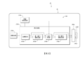
參考圖 3
,示出了氣體混合物設備10b
的實施方式的部件,該等部件包括測量控制系統110b
、啟動系統210b
、加壓腔室410b
、混合腔室510b
、第一壓力調節系統610b
以及第二壓力調節系統710b
。測量控制系統110b
可以包括計量刻度盤120
以及可以插入計量刻度盤120
的柱塞主體160
。啟動系統210b
可以包括致動桿220
和啟動開關260
。啟動系統210b
可以可操作地聯接到測量控制裝置110b
以控制氣體混合物設備10b
的操作。啟動系統210b
可以插入柱塞主體160
中。Referring to FIG. 3 , components of an embodiment of the
加壓腔室410b
可以包括殼體420
、容納氣體的罐436
、釋放容納在罐436
內的氣體的釋放機構444
、減少流出殼體420
的非氣體性材料或細菌性材料的量的過濾器448
、以及柱塞密封件460
。混合腔室510b
可以包括注射器主體520
。第一壓力調節系統610b
可以包括閥體和相關的閥部件。第二壓力調節系統710b
也可以包括相關的閥部件。
測量控制系統和啟動系統The pressurizing
參考圖 4
,示出了組合式測量控制系統110b
和啟動系統210b
的實施方式。測量控制系統110b
可以包括計量刻度盤120
和柱塞主體160
。啟動系統可以包括致動桿220
(圖 7
所示)和啟動開關260
。Referring to FIG. 4 , an embodiment of the combined
參考圖 5A
和圖 5B
,示出了氣體混合物設備10b
的計量刻度盤120
的實施方式,該計量刻度盤被配置為允許設備10b
的使用者選擇性地改變可注入體積的濃度。計量刻度盤120
包括兩個結構部件,即計量主體122
以及可以聯接到計量主體122
的計量蓋124
,以便允許計量刻度盤120
可釋放地附接到設備10b
的另一部件。這樣可以有利地促進設備的組裝,並且在一些可重複使用的實施方式中可以促進拆卸以用於再滅菌。在一些實施方式中,可以使用比如螺釘、鉚釘、夾子以及本領域已知的其他緊固機構等緊固件將計量蓋124
可釋放地附接到計量主體122
。將計量蓋124
附接到計量主體122
可以形成環形槽126
和環形唇128
,使得計量刻度盤120
可以附接到設備10b
的另一部件。例如,環形槽126
和環形唇128
可以對應於位於注射器主體520
上的凸緣526
。 5A and FIG. 5B, a
計量主體122
可以具有大致圓柱形的構件130
,該圓柱形構件具有位於頂端處的凸緣132
、以及基本上在圓柱形構件130
上居中並且在整個計量主體122
上延伸的通道134
。由於計量主體122
被配置為控制可注入體積的氣體的濃度,因此計量主體122
可以包括在完全組裝狀態下沿著設備10b
的使用者可見的表面的計量指示器136
。在所展示的實施方式中,計量指示器136
位於凸緣132
的頂部表面上,但是可以使用任何使用者可以看到的位置。計量指示器136
可以為裝置的使用者提供關於設備10b
的操作的資訊。在所展示的實施方式中,計量指示器136
顯示出18、19、20、21和22的一系列數字,其對應於在啟動設備10b
的情況下將產生可注入體積的六氟化硫(SF 6
)的濃度。如對於熟悉該項技術者而言顯而易見的是,所使用的範圍可以取決於所使用的氣體和該氣體之用途。此外,在一些實施方式中,此範圍可以進一步細分以提供對所需濃度的增強控制。The
計量主體122
可以具有多個槽138
、單個槽138以及與計量指示器136
相對應的可變擋塊142
。在所展示的實施方式中,計量主體122
具有沿著通道134
的內表面定位的五個單獨槽138
,其對應於上述五個整數值。在其他實施方式中,與計量指示器136
提供的值的數量相比,計量主體122
可以具有更少或更多槽。The
與該等槽138
中的每個槽相對應的是從槽138
向內延伸的可變擋塊142
。如上所述,該等可變擋塊142
可以呈從凸緣132
的頂部表面延伸的表面的形式,該可變擋塊下端表面142a
被設置成與管狀主體130
的底端間隔開設定距離。在一些實施方式中,可變擋塊142
不需要從頂部表面延伸,而是較小的突起,其下端表面142a
朝向圓柱形構件130
的底端設置在設定距離處。該等可變擋塊142
被配置為與容納在柱塞主體160
中的部件(比如閂鎖228
)或柱塞主體160
本身相互作用,以藉由在第一操作階段和第二操作階段期間限制柱塞主體160
的向後延伸來而該等階段期間控制混合腔室510b
的擴張體積(參見圖 2B
)。這樣,可變擋塊142
根據擋塊142
所對應的濃度而延伸不同的距離。例如,濃度為21%則向下延伸的距離小於濃度為20%時向下延伸的距離,由此使混合腔室510b
保持較大量的第一氣體。在第四階段期間(圖2D)添加經過濾的環境空氣之前,第三操作階段(圖2C)結束。這樣,當選擇21%的濃度時,可以允許柱塞主體160
向後延伸更大的距離,由此在第一操作階段期間允許混合腔室510b
更大地擴張。因此,應該顯而易見的是,可變擋塊142
用於控制第一操作階段的第一擴張體積。With
在多個槽138
的兩側的是從通道134
的內表面向內延伸的槽138。在一些實施方式中,槽138從通道134
的內表面向內延伸的距離大於可變擋塊142
。槽138可以被配置為一旦設備10b
已經被啟動就防止設備10b
切換到不同的濃度值。這樣可以在可能需要特定濃度的氣體且此值的任何微小變化都可能產生嚴重不利影響的應用中尤其重要。在所展示的實施方式中,槽138被配置為基本上減小在至少前兩個操作階段期間柱塞主體160
將旋轉到不同的可變擋塊142
的可能性。在某些實施方式中,如果期望恒定可變的計量裝置,則可以移除該等導軌。在這樣的實施方式中,可變擋塊142
可以可替代地具有斜坡形狀、而不是具有多個台階。On both sides of the plurality of
計量主體122
可以另外包括沿著通道134
的內表面的棘爪144
,該棘爪向內朝向通道134
的中心延伸。棘爪144
可以被鉸接並且被配置為使得棘爪144
可移動地變形並且在變形期間提供阻力。此棘爪144
可以對應於位於柱塞主體160
上的特徵以促進相對於所選濃度的正確取向。這樣的機構可以另外向裝置的使用者提供觸覺回饋,從而指示已經實現了正確的對準。此觸覺回饋可以有利地減小在不正確的取向上啟動的可能性。也可以使用其他類型的回饋機構和對準機構。
參考圖 6
,示出了柱塞主體160
的實施方式,其包括大致管狀的框架162
、在柱塞主體160
的一端處的手柄164
、位於二者之間的選擇環166
、以及在管狀框架162
上居中並在柱塞主體160
的整個長度上延伸的通道168
。管狀框架162
被配置為在計量刻度盤120
的通道134
內可滑動地平移並且部分可滑動地旋轉。Referring to Figure 6, there is shown an
管狀框架162
具有呈夾子形式的保持機構170
,該保持機構鉸鏈地附接到管狀框架162
。保持機構170
可以被配置為保持比如加壓腔室410b
的殼體420
等部件。保持機構170
有利地允許在不使用工具的情況下對部件進行附接,由此有利於組裝整個裝置的過程。另外,保持機構170
還可以被配置為使得可以從管狀框架162
上移除部件,從而允許設備10b
被重複使用,或者在其他實施方式中,在將再滅菌處理過程用於裝置的情況下允許重新使用設備10b
,由此有利於再滅菌處理過程。也可以使用其他類型的保持機構來代替所示實施方式中所示的夾子,並且可以包括比如螺釘等緊固件。The
管狀框架162
可以另外包括從管狀框架162
的外表面向外延伸的引導件172
。引導件172
可以從管狀框架162
的底端朝向管狀框架162
的頂端延伸一定距離。引導件172被配置為裝配在沿著計量主體122
的通道134
的內表面定位的多個槽138
和一個槽138內。這樣,引導件172當被定位在槽138
之間時可以防止柱塞主體160
旋轉。這樣可以有利地防止在開始第一操作階段之後柱塞主體160
移動到不同的可變擋塊142
並且由此降低可注入體積中的濃度不當的風險。引導件172的尺寸較佳的是設定為使得當柱塞主體160
被完全插入時,引導件172僅在槽138的稍下方,使得柱塞主體160
在初始操作階段期間可以自由地旋轉至不同的濃度值(參見圖 2A
)。但是,由於引導件172僅在槽138稍下方,一旦延伸了較短距離,引導件172就會被鎖定在所選定的導軌140
內。這種定位有利地使得引導件172在設備10b
啟動之後不久即被鎖定。此外,引導件172較佳的是從管狀框架162
向外僅延伸足以使其可以與槽138接觸、但是不足以使其與位於槽138之間的可變擋塊142
接觸的距離。因此,這樣可以使得引導件172在操作期間不受可變擋塊142
的干擾。The
管狀框架162
可以另外包括閂鎖孔174
,該閂鎖孔被配置為允許位於啟動桿220
上的閂鎖228
(圖7)從管狀框架162
向外突出。閂鎖孔174
較佳的是在引導件172的最頂部的正上方居中。如將在以下詳細討論的,在第一位置或「關閉」位置,閂鎖228
縮回,使得其不會延伸超過引導件172,並且因此不會與可變擋塊142
(參見圖 8
A)接觸。當處於第二位置時,閂鎖228
從管狀框架162
向外延伸超過引導件172,使得閂鎖228
可以與可變擋塊140
(比如下表面142
a)接觸,由此防止在閂鎖處於第二位置(見圖 8B
)時柱塞主體160
進一步延伸。這樣,腔室510
b可以擴張達到的體積由閂鎖228
和表面142a
限制。在一些實施方式中,閂鎖孔174
可以被放置成使得在初始操作階段(圖 2A
所示)期間柱塞主體160
未正確地定向在計量刻度盤120
內的情況下可以防止閂鎖228
藉由計量刻度盤120
的導軌140
向外延伸進入第二位置或「打開」位置。這樣可以有利地防止設備10b
在不正確定向時啟動。The
管狀框架162
可以另外包括沿其外表面定位的呈切口形式的棘爪槽176
。棘爪槽176
被配置為接收計量主體122
的棘爪144
,由此提供用於當棘爪144
被接收在其中一個棘爪槽176
中時藉由提供旋轉阻力而確保柱塞主體160
正確地定向在計量主體122
內的機構。此外,有利地,在將棘爪144
接收在棘爪槽176
內的每個點處,當柱塞主體160
正確地定向在計量主體120
內時,設備10b
的使用者也可以接收觸覺回饋。The
繼續參考圖6,環166
可以包括從管狀框架162
的外表面延伸的環形突起。選擇環166
可以另外包括選擇指示器178
,其可以採取位於選擇環166
上的較小突起的形式。選擇指示器178
可以對應於位於計量主體122
(圖 5A
)上的計量指示器136
並且可以與之對準,以指示當柱塞主體160
被定向位於與閂鎖228
和對應表面142a
的對準相對應的位置時將會獲得的濃度水平。這樣的系統可以有利地向裝置的使用者提供關於所選濃度水平的容易查看的資訊。選擇指示器178
可以有利地被著色以利於設備10b
的使用。With continued reference to FIG. 6, the
手柄164
可以相對於管狀框架162
的縱向軸線在徑向方向上延伸。手柄164
可以成形為使得設備10b
的使用者可以抓住手柄164
並且使用該手柄以進一步向後伸展柱塞主體160
並且從設備10b
中伸出,或者進一步將柱塞主體160
向前壓入設備10b
中。手柄164
可以另外包括用於接收用於啟動開關260
的聯接機構的孔180
。啟動開關260
由此可以圍繞聯接機構旋轉,以便對位於柱塞主體160
內的致動桿220
進行操作。The
參考圖7
,示出了啟動系統210b
的實施方式,該啟動系統包括致動桿組件220
和啟動開關260
。致動桿組件220
具有大致長形的主體,該主體具有第一端處的致動銷222
、第二端處的致動桿224
、以及位於中間部分的閂鎖運動部分226
。致動銷222
被配置為被接納在加壓腔室410b
的殼體420
內、並且當處於第二位置或「打開」位置時啟動容納在加壓腔室中的氣體的釋放。Referring to FIG. 7 , an embodiment of the
致動桿224
被配置為鄰接並遵循啟動開關260
的輪廓表面262
(圖 9
)。致動桿224
還較佳的是成形為使得截面輪廓與位於柱塞主體160
的手柄164
附近的通道169
(如圖 8
所示)的頂部中的截面輪廓相匹配。較佳的是,截面輪廓不是基本上圓形的,使得基本上防止致動桿220
在柱塞主體160
的通道168
內旋轉。閂鎖運動部分226
成形為使得當閂鎖228
可沿致動桿220
的閂鎖運動部分226
滑動地平移時,閂鎖228
平移。這樣,閂鎖228
具有孔230
,該孔的截面形狀類似於閂鎖運動部分226
的截面形狀。The
啟動開關260
被配置為使致動桿220
平移通過柱塞主體160
的一部分並且通過加壓腔室410b
的殼體420
以啟動加壓腔室中所容納的氣體的釋放。這樣,啟動開關260
可以包括凸輪,該凸輪的沿表面的成形輪廓262
被配置為與致動桿224
接觸。啟動開關260
也可以具有孔264
,該孔被配置為接收銷266
,使得啟動開關260
可以圍繞銷266
旋轉。在所展示的實施方式中,啟動開關260
被示出處於第一位置或「關閉」位置。在此第一位置,銷266
與接觸致動桿的輪廓表面262
之間的距離可以是減小的距離,使得致動桿保持在第一位置或「關閉」位置。The
當圍繞銷266
旋轉到第二位置或「打開」位置時,銷266
與接觸致動桿224
的輪廓表面262
之間的距離係增加的距離,由此將致動桿220
平移到第二位置或「打開」位置進一步進入加壓腔室410b
的殼體420
。如將在以下相對於圖 10
和圖 11
更詳細地描述的,移動到第二位置或「打開」位置可以被配置為釋放加壓腔室410
b中的氣體。啟動開關260
可以是較佳的是可以保持在第一位置或第二位置而無需使用者將開關保持在該位置的任何類型的開關。在所展示的實施方式中,使用旋轉桿。也可以使用其他開關,比如螺釘、閂鎖、彈簧載入銷或本領域已知的任何其他開關。When rotating around the
參考圖 8
A和圖 8
B,示出了啟動系統210b
的操作的圖示,其包括測量控制系統110b
和啟動系統210b
的一些部件。如此處所示,閂鎖228
容納在閂鎖孔174
內,使得閂鎖不能朝向柱塞主體160
的前端或後端平移。這樣,當致動桿220
在向前或後向方向上平移時,閂鎖228
必須遵循致動桿220
的閂鎖運動部分226
的輪廓。這樣,這提供了當啟動開關260
以及因此致動桿220
處於相應的第二位置時閂鎖228
在第二位置的聯接運動的優點。此外,由於閂鎖228
的運動與另一啟動開關260
和致動桿220
的運動相聯接,因此在阻止閂鎖228
運動到第二位置的情況下也防止啟動開關260
和致動桿220
運動到第二位置。注意,如上所述,當處於第二位置或「打開」位置時,閂鎖228
可以從柱塞主體160
突出,由此限制柱塞主體160
的延伸,如圖 8B
所示。
加壓腔室和第一壓力調節系統Referring FIGS. 8 A and 8 B, a diagram showing the
參考圖 9
,示出了包括啟動系統210b
、混合系統310b
的加壓腔室410b
以及混合系統310b
的第一壓力調節系統610b
的一些部件的實施方式。如圖所示,加壓腔室410b
可以具有殼體420
,該殼體具有位於殼體420
的第一端附近的環形槽422
。環形槽422
可以被配置為接收位於柱塞主體160
上的保持機構170
。殼體420
還可以具有位於殼體420
的第二端處的柱塞密封件460
。柱塞密封件460
被配置為提供用於限定混合腔室510b
的氣密性密封件。Referring to Figure 9, there is shown an embodiment comprising a starting
參考圖 10
,係加壓腔室410b
和第一壓力調節系統610b
的截面視圖。環形槽422
位於第一端或後向端,並且圓錐形或截頭圓錐形表面424
位於第二端或前向端、與柱塞密封件460
的形狀相對應。殼體420
可以另外成形為使得其具有環形突起426
和環形槽428
,該環形槽被配置為接收柱塞密封件460
的唇部462
。此配置有利地確保柱塞密封件460
保持連接到殼體420
並形成密封以防止容納在殼體主體420
中的任何氣體洩漏。柱塞密封件460
的唇部462
可以緊密地裝配在殼體420
的環形槽428
內以提供增強的密封件。Referring to FIG. 10 , it is a cross-sectional view of the pressurizing
內部空間430
基本上被殼體420
封閉,並且可以被分成第一單獨部分432
和第二單獨部分434
。呈比如罐436
等結構單元形式的第三單獨部分可以容納在殼體420
的第二單獨部分434
中。此罐可以容納用於混合到混合腔室510
b中的氣體。在罐中提供氣體係有利的,因為其利於設備10b
的製造,因為可以允許將罐與加壓腔室410b
的其他部件單獨地製造。在設備10b
可重複使用的一些實施方式中,罐可以被更換。The
罐436
具有與致動銷222
接觸的第一端或後向端、以及密封的第二端或前向端437
。密封件438
在罐436
的一端,密封件基本上減少了任何氣體從第一單獨部分432
洩漏到第二單獨部分434
。這樣有利地減小了氣體洩漏出致動器孔440
和設備10b
之外的可能性。The can 436 has a first end or rear end in contact with the
殼體420
還可以包括比如彈簧等偏置機構442
,其在背離殼體420
第二端的方向上在密封件上施加力。在所展示的實施方式中,偏置機構442
位於第一單獨部分432
中。這樣減小了在沒有被使用者啟動時罐436
移動到第一單獨部分432
中並且可能釋放其中容納的氣體的可能性。此外,偏置機構442
還可以提供抵抗啟動的反作用力,使得使用者不會意外啟動該裝置。偏置機構442
可以被配置為施加足夠的力,使得在第一操作階段和第二操作階段完成並且啟動開關160
返回到第一位置或「關閉」位置之後,偏置機構442
施加足夠的力而使得致動桿220
返回其第一位置或「關閉」位置,由此使閂鎖228
返回其第一位置或「關閉」位置。一旦閂鎖228
返回到其第一位置或「關閉」位置,柱塞主體160
的延伸就不再受到限制,並且第三操作階段可以開始。如果偏置機構442
沒有在致動桿220
上施加足夠的力,則進入第三操作階段可能更加困難。The
殼體420
還可以具有釋放機構444
,比如在這個設備10b
的實施方式中所展示的針頭或先導尖頭,該釋放機構可以被配置為刺穿罐436
的密封的第二端437
,以由於通道446
軸向延伸穿過釋放機構444
而藉由釋放機構444
將氣體釋放到第一單獨部分432
罐中。由於第一單獨部分432
中的高壓,第一壓力調節系統610b
可以打開,以允許氣體逸出至柱塞密封件460
的前部並進入混合腔室510b
。在一些實施方式中,可以沿著流動路徑放置過濾器448
,使得異物進入混合腔室510b
的可能性降低。在一些實施方式中,過濾器448
可以被配置為濾出細菌。The
柱塞密封件460
被配置為藉由形成針對混合腔室510b
的密封來部分地限定混合腔室510b
的可注入體積。柱塞密封件460
可以具有大致圓柱形的主體,該主體具有環形突起464
並且在前向端處具有圓錐形或截頭圓錐形面466
,該環形突起被配置為與混合腔室510b
的內表面接觸。截頭圓錐面466
可以另外包括以圓柱形主體為中心的孔468
,該孔被配置為接收第一壓力調節系統610b
的部件。此外,主體還可以在後向端上具有由唇部462
限定的開口470
,該開口被配置為接收殼體420
。The
繼續參考圖 10
,第一壓力調節系統610b
的實施方式被示出處於第一位置或「關閉」位置。第一壓力調節系統610b
可以包括:在一端包括多個孔622
的閥體620
;延伸穿過閥體620
的閥桿624
,該桿在後端具有被配置為與偏置機構628
接觸的座部626
、並且在前端具有被配置為與密封環632
接觸的頭部630
。With continued reference to FIG. 10 , an embodiment of the first
在操作期間,偏置機構628
可以在後向方向上對座部626
施加偏置力,使得頭部630
抵靠密封環632
和閥體620
偏置,由此減少或防止氣體流過閥體620
並最終進入混合腔室510b
。由於偏置機構628
的定向,第一壓力調節系統610b
保持關閉,直到加壓腔室410b
內的壓力超過閾值。可以藉由改變壓縮偏置機構628
所需的力的大小來配置此閾值。During operation, the
參考圖 11
,第一壓力調節系統610b
的實施方式被示出為處於「打開」位置,其中加壓腔室410b
內的壓力超過混合腔室510b
內的壓力。在一些較佳的實施方式中,壓力差很大。由於此壓力差,在閥部件上施加足夠的力而導致將要克服偏置機構628
,由此允許氣體從閥體620
流出並進入混合腔室510b
。Referring to FIG. 11 , an embodiment of the first
由於設備10b
的多個操作階段,這種配置對於第一壓力調節系統610b
係有利的。在至少一部分第二操作階段以及第一操作階段期間,壓力差使閥保持打開。但是,一旦壓力差不足以超過閾值,則閥將保持在關閉位置,以防止任何其他氣體流入混合腔室並可能破壞所計算出的壓力/濃度。Due to the multiple stages of operation of the
參考圖 12
,示出了混合腔室510b
的實施方式,其包括注射器主體520
、第二壓力調節系統710b
以及上述系統的多個不同的部件。注射器主體520
可以是圓柱形主體,並且可以包括後端處的孔522
以及前端處的螺紋噴嘴524
。注射器主體還具有被配置為與計量裝置120
接合的凸緣526
。混合腔室510b
可以由注射器主體520
的內壁和柱塞密封件460
來限定。此外,注射器主體可以沿著其外表面包括對應於選定濃度的指示器528
。該等指示器528
可以有利地向使用者提供所選濃度的視覺確認。Referring to FIG. 12 , an embodiment of a mixing
參考圖 13
,示出了第二壓力調節系統710b
的實施方式,其包括閥體720
,該體可以包括球722
、偏置機構724
、座部726
以及密封機構728
。第二壓力調節系統710b
還可以包括第二偏置機構730
和銷致動器732
。Referring to FIG. 13 , an embodiment of a second
閥體720
可以在注射器主體520
的噴嘴524
附近的內部空間734
內平移。在一些實施方式中,由於第二偏置機構730
,閥體720
平移,使得閥體720
的凸緣735
壓靠噴嘴524
的內唇736
。此外,偏置機構724
可以密封並阻止流過閥體720
,直到在球722
上施加足夠的力以克服偏置力。當混合腔室510b
與大氣之間的壓力差超過閾值時,會發生這種情況。The
在操作期間,由於容納在混合腔室510b
中的增加的壓力,導致第二壓力調節系統710b
在第一操作階段和第二操作階段期間打開。一旦壓力差不足以使閥體720
打開,則第二操作階段完成,並且使用者可以前進至第三操作階段。During operation, due to the increased pressure contained in the mixing
參考圖 14
,過濾器760
附接到第二壓力調節系統710b
的出口。過濾器760
具有第一開口端762
、第二開口端766
以及位於它們之間的過濾元件768
,該第一開口端具有凸緣764
,該凸緣被配置為與螺紋噴嘴524
的內部上的螺紋接合。這樣,氣體可以在第一開口端762
至第二開口766
之間的兩個方向上通過並且在此過程中被過濾。Referring to FIG. 14 , the
在一些實施方式中,第一開口端762
的內表面在第二開口端766
的方向上逐漸變細,使得形狀對應於閥體720
的形狀。當附接件760
被擰入螺紋噴嘴524
中時,附接件760
朝向注射器主體520
的後端抵抗第二偏置機構730
的偏置力而與閥體720
接合並且使閥體720
平移。這樣致使球722
與銷致動器732
接觸,由此致使球從閥體720
的內表面移開而由此使得氣體在任一方向上流過閥體720
。這種配置可以使得混合腔室510b
在環境壓力下進一步擴張並且用於對吸入混合腔室510b
中的空氣進行過濾。因此,在此位置,可以執行第三操作階段。一旦第三操作階段完成,就可以移除過濾器760
。由於第二偏置機構730
的力,閥體720
可以平移遠離銷致動器732
,使得閥體720
保持關閉,直到使用者例如藉由對用於將治療性氣體注入患者體內的注入針頭進行附接而決定使用混合腔室510
內的治療性氣體為止。
測量控制系統和啟動系統的實施方式In some embodiments, the inner surface of the first
圖15 -31 展示了該設備的測量控制系統的部件的另外的實施方式。 Figures 15-31 show additional embodiments of the components of the measurement control system of the device.
圖15A
和圖 15B
示出了計量刻度盤820
的實施方式,該計量刻度盤可以被配置為允許裝置的使用者選擇用於可注入體積的流體濃度。類似於其他實施方式,計量刻度盤820
可以包括兩個部件,比如計量主體822
以及可以可移除地附接到計量主體822
的計量蓋824
。 15A and 15B illustrate
繼續參考圖 15A
和圖 15B
,計量主體822
可以具有大致圓柱形的構件830
,其具有位於計量主體822
的頂部部分的凸緣832
。計量主體822
可以包括通道834
,該通道基本上在圓柱形構件830
上居中並且在整個計量主體822
上延伸。在一些實施方式中,比如圖 15A
所展示的,大致圓柱形的構件830
可以包括附加表面特徵,比如直徑增大的部分831
,其可以潛在地鍵接到其所插入的裝置中。With continued reference to FIGS. 15A and 15B, the
與計量刻度盤或類似計量機構的其他實施方式一樣,此實施方式還可以包括沿計量主體820
的表面定位的計量指示器836
。在此示出的實施方式中,計量指示器836
位於凸緣832
的頂部表面上,但是可以使用任何其他可見位置,比如沿著凸緣832
的周邊部分。在所展示的實施方式中,計量指示器836
示出了18、19、20、21和22的一系列數字,其對應於可以在組件的可注入體積中產生的六氟化硫(SF 6
)的濃度。As with other embodiments of the metering dial or similar metering mechanism, this embodiment may also include a
與計量刻度盤和其他計量機構的其他實施方式一樣,計量主體822
可以具有槽838
、導軌840
以及對應於計量指示器836
的可變擋塊。As with other embodiments of the metering dial and other metering mechanisms, the
計量刻度盤820
的所展示的實施方式的可變擋塊的操作可以類似於計量刻度盤和計量機構的其他實施方式的操作。可變擋塊可以被配置為與容納在柱塞主體860
內的部件(比如閂鎖928
或類似的突出結構)相互作用,以在至少一些操作階段期間控制可注入體積的腔室的擴張。在一些實施方式中,可變擋塊可以藉由在不同階段期間限制柱塞主體860
的向後延伸來執行此任務。這樣,可變擋塊根據擋塊所對應的濃度而延伸不同的距離。The operation of the variable stop of the illustrated embodiment of the
參考圖 16
,示出了柱塞主體860
的實施方式,其可以包括大致管狀的框架862
、在柱塞主體860
的一端處的手柄864
、位於它們之間的選擇器構件866
,以及在管狀框架862
上居中的通道868
,該通道可以在柱塞主體860
的整個長度上延伸或者可以在管狀框架862
的長度的至少一部分上延伸。管狀框架862
可以被配置為在計量刻度盤的通道內可滑動地平移和可滑動地旋轉。Referring to Figure 16, there is shown an
繼續參考圖 16
,管狀框架862
可以包括閂鎖孔874
,該閂鎖孔被配置為允許位於啟動桿920
上並容納在通道868
內的閂鎖928
從管狀框架862
向外突出。如所展示的實施方式中所示,閂鎖孔874
可以在防護罩872
的最上方部分的正上方居中。在其他實施方式中,閂鎖孔874
也可以沿著管狀框架862
位於不同的位置,並且在使用多個閂鎖的情況下可以包含一個以上的閂鎖孔。With continued reference to FIG. 16 , the
如以下更詳細地描述的,在第一位置、「初始」位置或「預啟動」位置,閂鎖928
的尺寸可以設定為沒有延伸超過防護罩872
,並且因此不與可變擋塊或類似結構接觸。當處於第二位置或「打開」位置時,閂鎖928
可以從管狀框架862
向外延伸超過防護罩872
,使得閂鎖928
可以與可變擋塊或類似結構接觸,由此防止或顯著減小當閂鎖處於第二位置時柱塞主體860
進一步伸展的可能性。As described in more detail below, in the first position, the "initial" position, or the "pre-start" position, the
繼續參考圖 16 、圖25a
和圖 25b
,啟動開關960
可以被配置為使致動桿920
通過柱塞主體860
朝向第一殼體構件1020
平移,以啟動用於釋放容納在其中的氣體的機構。這樣,像其他實施方式的啟動開關一樣,啟動開關960
可以是凸輪,該凸輪具有沿著表面定位的被配置為與致動器主體922
接觸的成形輪廓962
。啟動開關960
可以另外包括孔964
,該孔被配置為接收銷,使得啟動開關960
可以圍繞銷旋轉。熟悉該項技術者應當理解,啟動開關960
可以是較佳的是可以保持在第一位置、第二位置或更多位置而無需使用者將開關保持在該位置的任何類型的開關。在所展示的實施方式中,使用旋轉桿。也可以使用其他開關,比如螺釘、閂鎖、彈簧載入銷或本領域已知的任何其他開關。With continued reference to FIG. 16, FIGS. 25a and 25b, the
參考圖 18
,啟動開關960
被示出處於第一位置、「初始」位置或「預啟動」位置。例如,這可以是在第一操作階段之前的位置。在此第一位置,銷966
與和致動器主體922
接觸的輪廓表面962
之間的距離可以是第一距離,使得致動器主體922
位於距柱塞主體860
的管狀框架862
的端部第一距離處。Referring to FIG. 18 , the
如圖 19
所示,在一些實施方式中,啟動開關960
可以朝向更為豎直地定向的位置、即第二位置或「打開」位置旋轉,其中從銷966
到與致動器主體922
接觸的輪廓表面962
的距離可以是第二距離,使得致動器主體922
位於距柱塞主體860
的管狀框架862
的端部第二距離處。這可以對應於在第一操作階段和第二操作階段期間的啟動開關960
的位置。在一些實施方式中,第二距離可以大於第一距離。如將關於圖 25
-27
更詳細地描述的,這樣可以致使致動器主體922
朝向加壓腔室的第一殼體構件1020
平移。這種平移可以啟動釋放容納在加壓腔室內的流體或氣體。As shown in Figure 19, in some embodiments, the
如圖 20
所示,在一些實施方式中,啟動開關960
也可以朝向更為水平地定向的位置、即第三位置或「關閉」位置旋轉,其中從銷966
到與致動器主體922
接觸的輪廓表面962
的距離可以是第三距離,使得致動器主體922
位於距柱塞主體860
的管狀框架862
的端部第三距離處。這可以對應於將可注入體積注入到患者體內之前的第三操作階段和/或最終階段。此第三距離可以小於或等於第一距離和/或第二距離。在一些實施方式中,朝向第三位置的旋轉可以致使致動器主體922
平移遠離加壓腔室的第一殼體構件1020
,使得沒有流體或氣體從加壓腔室釋放。As shown in FIG. 20, in some embodiments, the
視需要,可以包括互鎖機構以控制和限制啟動開關960
的運動。If desired, an interlocking mechanism may be included to control and limit the movement of the
參考圖 21
-23
,示出了啟動系統的實施方式的操作。如所展示的實施方式中所示、並且與其他實施方式類似,閂鎖928
可以容納在閂鎖孔874
內,使得閂鎖不能朝向柱塞主體860
的前端或後端平移。在這樣的實施方式中,當致動桿920
在向前或後向方向上平移時,閂鎖928
被配置為遵循致動桿920
的閂鎖運動部分926
的輪廓。With reference to Figure 21 - 23 illustrate operation of the embodiment of the system startup. As shown in the illustrated embodiment, and similar to other embodiments, the
圖21
示出了處於第一位置、「初始」位置或「預啟動」位置的實施方式。如在此所示的,閂鎖928
可以被定位成使得其充分地從柱塞主體860
向外突出,使得如果向後延伸,則閂鎖928
將與位於計量主體922
上的可變擋塊接觸並且防止任何進一步的延伸。在其他實施方式中,當處於第一位置時,閂鎖928
可以被配置為不從主體860
向外突出以防止這種延伸。當移動到第二位置或「打開」位置時,如圖 22
所示,閂鎖928
可以從柱塞主體860
充分向外突出,使得閂鎖928
可以與位於計量刻度盤820
上的可變擋塊或類似結構接觸,由此防止任何進一步的向後延伸。如圖 23
所展示的,當旋轉到第三位置或「關閉」位置時,閂鎖928
可在閂鎖孔874
內充分縮回,使得閂鎖928
不再與位於計量刻度盤820
上的可變擋塊或類似結構接觸,由此允許柱塞主體860
進一步向後延伸。 Figure 21 shows an embodiment in a first position, an "initial" position or a "pre-start" position. As shown here, the
繼續參考圖 21
-23
,比如棘爪的棘輪構件886
可以附接到柱塞主體860
。棘輪構件886
可以被鉸接,並且被配置為使得棘輪構件886
可移動地變形並在變形期間提供阻力。棘輪構件886
可以對應於位於柱塞主體計量刻度盤820
上的特徵(比如圖 15b
中的切口842
)以促進與所選濃度有關的正確定向。為了允許棘輪構件886
向內變形,致動器主體924
可以包括凹部或凹口980
。此凹部980
可以被配置為僅允許棘輪構件886
在第一位置和第三位置向內變形,而棘輪構件886
在處於第二位置時被限制向內變形。這樣可以提供減少在裝置操作期間柱塞主體860
可以旋轉的可能性的手段。
加壓腔室的實施方式With continued reference to FIGS. 21 - 23, such as a
參考圖 24
-25
B,示出了加壓腔室的實施方式以及啟動系統的部件。如圖所示,加壓腔室可以具有兩部分式殼體,該殼體具有可相對於彼此平移的第一殼體構件1020
和第二殼體構件1022
。如所展示的實施方式中所示,兩個構件1020
、1022
可以具有大致圓柱形的形狀,使得兩個構件1020
、1022
的一些部分或所有部分都可以被接收在柱塞主體860
的通道868
內。在一些實施方式中,兩個構件1020
、1022
可以彼此分離,以允許兩個構件1020
、1022
自由地平移。在其他實施方式中,兩部分式殼體可以被附接,同時仍然允許構件1020
、1022
相對於彼此平移。這種附接可以用於增加兩個構件1020
、1022
的穩定性。Referring to FIG 24 - 25 B, shows the components of the system embodiments and start pressurizing chamber. As shown, the pressurized chamber may have a two-part housing having a
如所展示的實施方式中所示、並且與加壓腔室的其他實施方式類似,環形槽1024
可以位於第二殼體構件1022
上。在所展示的實施方式中,環形槽1024
位於與第一殼體構件1020
相反的一端,然而可以選擇其他可能的位置。環形槽1024
可以設定尺寸、並且被配置為容納柱塞主體860
的保持翼部870
(圖 25A
所示),從而允許使用卡扣配合連接將第二殼體構件1022
緊固到柱塞主體860
。為了有利於將第二殼體構件1022
插入柱塞主體860
的通道868
中,所插入的端部可以稍微變細。在一些實施方式中,第二殼體構件1022
可以可移除地附接到柱塞主體860
,由此允許替換容納在其中的某些部分。例如,在一些實施方式中,儲存構件1030
或罐可以被容納在兩部分式殼體內。兩部分式殼體還可以具有柱塞端1060
,該柱塞端帶有比如橡膠O形圈等柱塞密封件1061
,該柱塞密封件被配置為與注射器主體1120
密封接觸並且形成用於限定腔室以容納可注入體積的密封件,這樣的腔室可能用作混合腔室。可以在柱塞端1060
周圍使用其他類型的密封構件以形成這種密封。As shown in the illustrated embodiment, and similar to other embodiments of the pressurized chamber, the
圖25A
和圖 25B
係當該設備處於第一位置、「初始」位置或「預啟動」位置時圖 24
所示的實施方式的截面視圖。如在圖 25B
更清楚地展示的,在第一位置,桿偏置構件924
(比如螺旋彈簧)可以與致動器主體922
和第一殼體構件1020
接觸;然而,致動器主體922
可以不與第一殼體構件1020
直接接觸。在第一位置,桿偏置構件924
可以在前向方向上在第一殼體構件1020
上施加力,並且在後向方向上在致動器主體922
上施加力,使得致動器主體922
保持與啟動開關960
接觸。在此位置,當第一殼體構件1020
試圖朝向第二殼體構件1022
平移時,施加在第一殼體構件1020
上的前向力可以使第一殼體構件1020
向容納在其中的儲存構件1030
施加力。較佳的是,在第一位置,由於儲存構件1030
中所容納的機構(如將在圖 28
-29
中進一步詳細討論的),第一殼體構件1020
施加在儲存構件1030
上的力將不足以使儲存構件1030
朝向第二殼體構件1022
平移。這樣,當處於第一位置時,容納在儲存構件1030
內的任何氣體或流體將保持容納在儲存構件1030
內。 FIG. 25A and FIG. 25B based sectional view when the device is in a first position, "initial" position or the "advance start" position shown in the embodiment 24 of FIG. As shown more clearly in FIG. 25B , in the first position, the lever biasing member 924 (such as a coil spring) may be in contact with the
圖26A
和圖 26B
係當設備處於第二位置或「打開」位置時圖 24
所示的實施方式的截面視圖。如在圖 26
B中更清楚地展示的,當處於第二位置時,致動器主體922
和桿偏置構件924
均可以與第一殼體構件1020
直接接觸。由於這種直接接觸,可以在第一殼體構件1020
施加更大的力,使得第一殼體構件1020
可以在前向方向上平移,由此使得儲存構件1030
在前向方向上平移。然後,儲存構件1030
的這種前向平移可以啟動從儲存構件1030
釋放氣體。在其他實施方式中,致動器主體922
不需要與第一殼體構件1020
直接接觸,因為在這樣的實施方式中,由於桿偏置構件924
的壓縮而由桿偏置構件924
施加的力的增加可以足以使得第一殼體構件1020
在前向方向上平移以導致啟動從儲存構件1030
釋放氣體。 26A and 26B system-sectional view of the device when in the second position or "open" position 24 shown in the embodiment of FIG. As shown more clearly in FIG. 26B , when in the second position, both the
圖27A
和圖 27B
係當設備處於第三位置或「關閉」位置時圖 24
所示的第二實施方式的截面視圖。如圖 27
B所示,當處於第三位置時,致動器主體922
與第一殼體構件1020
接觸。此外,在一些實施方式中,由於銷966
與輪廓表面962
之間的距離減小,由桿偏置構件924
在後向方向上施加在致動器主體922
上的力可以使得致動器主體922
朝向輪廓表面962
平移,使得致動器主體922
保持與啟動開關960
接觸。桿偏置構件924
的這種擴張導致桿偏置構件924
施加在第一殼體構件1020
上的力減小。由於這種減小的力以及由於位於儲存構件1030
或罐內的其他機構,儲存構件1030
可以恢復到關閉狀態,由此防止任何其他氣體釋放到腔室中以容納可注入體積,該腔室也可以用作混合腔室。 FIGS 27A and 27B is a cross-sectional view of the line when the device according to the second embodiment shown in FIG. 24 or the third position "closed" position. As shown in FIG. 27 B, when in the third position,
圖28
係加壓腔室的實施方式的截面視圖。第一殼體構件1020
和第二殼體構件1022
具有容納在其中的容納比如氣體等流體的儲存構件1030
或罐(比如微圓柱體)。在一些實施方式中,第二構件1022
在與第一構件1020
相對的一端具有形成柱塞端1060
的圓錐形或截頭圓錐形表面。在一些實施方式中,第二構件1022
和柱塞端1060
形成整體單元。柱塞端1060
可以具有環形槽,該環形槽被配置為接收柱塞密封件1061
(比如橡膠O形圈)以形成用於可注入體積的腔室,該腔室也可用作混合腔室。 28 is a cross-sectional view of an embodiment of a pressurized chamber. The
第一殼體構件1020
可以包括被配置為接觸並接收儲存構件1030
的第一端的凹入部分1026
或凹口部分。凹入部分1026
的形狀應較佳的是對應於儲存構件1030
的第一端的形狀。在其他實施方式中,第一殼體構件1020
可以不包括凹入部分1026
。第二殼體構件1022
可以包括內部空間1028
,該內部空間被設定尺寸並且被配置為接收儲存構件1030
的第二端。在一些實施方式中,內部空間1028
可以包括與儲存構件1030
的第二端接觸的殼體密封件1029
。在一些實施方式中,殼體密封件1029
產生足夠的密封,使得幾乎沒有氣體向後洩漏穿過內部空間1028
。在一些實施方式中,內部空間1028
還可以在儲存構件1030
周圍提供總體上緊貼的配合,以確保儲存構件1030
通常僅在前向方向和後向方向上平移。這樣有利地減小了儲存構件1030
的第二端與殼體密封件1029
之間的密封被破壞的可能性。The
繼續參考圖 28
,比如所展示的罐或微圓柱體等儲存構件1030
可以包括主體部分1040
和頭部1042
。如所展示的實施方式中所示,主體部分1040
可以具有帶有半球形的第一端的大致圓柱形的形狀。主體部分1040
與頭部1042
結合可以形成內部空間1041
,以在可以與大氣氣體不同的第一壓力和濃度下容納比如呈氣態的氣體或呈液體形式的流體或兩者的組合。例如,此類氣體可以包括但不限於可膨脹氣體、眼科氣體(比如SF 6
、C 3
F 8
、C 2
F 6
或類似氣體)、推進劑氣體(比如CO 2
)、製冷劑氣體(比如N 2
O)以及其他各種類型的氣體。可以選擇內部空間1041
的尺寸,使得在該體積內可以容納單位劑量或一次性劑量。可以為主體部分1040
選擇其他形狀。With continued reference to FIG. 28 , the
頭部1042
可以具有大致管狀的形狀,其外徑與主體部分1040
的內徑相匹配。頭部1042
可以具有內部通道和凸緣1044
。如所展示的實施方式中所示,頭部1042
的第一端可以具有直徑與通道直徑相匹配的開口,並且頭部的第二端可以具有直徑小於通道直徑的開口1046
。在一些實施方式中,主體部分1040
和頭部1042
可以是稍後附接的單獨部件。這樣潛在地有利地允許在組裝之前對頭部1042
的內部部件進行組裝。一旦所有部件組裝在頭部1042
內,就可以將頭部1042
接納在主體部分1040
內、並且使用比如黏合劑、焊接等裝置和機制來緊固頭部。在一些實施方式中,比如圖 28
所示,凸緣1044
可以鄰接主體部分1040
並且沿此表面黏附或焊接。在其他實施方式中,主體部分1040
和頭部1042
可以形成整體單元。The
頭部1042
可以容納儲存構件壓力調節系統,該系統可以形成第一壓力調節系統的一部分並且可以在通道內採取內部閥機構的形式。內部閥機構可以包括保持環1048
、閥座1050
、內部偏置構件或機構1052
(比如彈簧)、閥活塞1054
以及活塞密封件1056
。保持環1048
可以放置在位於頭部1042
上的環形槽1058
內。保持環1048
可以由彈性材料製成,使得保持環可以在裝配到槽1058
中之前變形。閥座1050
可以放置在保持環1048
與頭部1042
的第二端之間。在一些實施方式中,閥座1050
可以是外徑大約等於頭部1042
的內徑的環。The
閥活塞1054
可以具有大致圓柱形的形狀並且被放置在閥座1050
與頭部1042
的第二端之間。閥活塞1054
的外徑可以被選擇為大約等於頭部1042
的內徑。如所展示的實施方式中所示,閥活塞可以包括被配置為接收活塞密封件1056
的環形槽、沿著活塞的周邊定位的流體路徑1055
或通道、以及突起1057
。流體路徑1055
可以被配置為允許流體在閥活塞1054
與頭部1042
之間穿過。在所展示的實施方式中,總共包括四個流體路徑;但是,可以使用更少或更多的流體路徑。在一些實施方式中,突起1057
可以是具有與開口1046
的直徑相對應的較小直徑的圓柱形構件。突起1057
可以被配置為裝配在開口1046
內。在一些實施方式中,突起1057
可以與頭部1042
的端面齊平。在其他實施方式中,突起1057
可以凹入開口內或延伸超過端面。偏置機構1052
可以放置在閥座1050
與活塞1054
之間以在前向方向上在閥活塞1054
上施加力,使得在活塞密封件1056
與頭部1042
之間形成密封。在其他實施方式中,可以使用其他類型的閥設計,比如球閥、提升閥或本文中提及或本領域已知的任何其他閥。The
在一些實施方式中,內部偏置機構1052
可以被配置為使得當啟動開關處於第一位置或「預啟動」位置時,內部閥機構將不會由於施加到其上的任何力(比如由於桿偏置機構924
經由第一殼體構件1020
施加到儲存構件1030
上的力)而打開。在一些實施方式中,內部偏置機構1052
可以被配置為使得當啟動開關處於第二位置或「打開」位置時,內部閥機構將由於施加到其上的力而打開。在一些實施方式中,內部偏置機構1052
可以被配置為使得當啟動開關處於第三位置或「關閉」位置時,內部閥機構將不會由於施加到其上的任何力(比如由於桿偏置機構924
經由第一殼體構件1020
施加到儲存構件1030
上的力)而打開。In some embodiments, the
在一些實施方式中,儲存構件1030
可以包括集成在儲存構件1030
的比如頭部1042
等部分中的比如過濾器等其他結構。儲存構件1030
可以包括放置在頭部1042
上和開口1046
上的膜或其他密封結構以提供附加密封,這樣可以有利地延長儲存構件1030
的使用壽命。膜或密封結構可以被比如銷1059
等突出構件或任何其他類似的釋放機構刺穿。在一些實施方式中,釋放機構可以是例如被稱為「玻璃原料」的多孔材料。儲存構件1030
還可以包括附加閥構件,其可以用作安全閥以減小在儲存構件1030
內所包含的壓力超過某些操作極限的情況下發生破裂的可能性。儲存構件1030
還可以被配置為以受控的方式破裂以減少嚴重故障的可能性。In some embodiments, the
在一些實施方式中,儲存構件1030
以及比如內部閥等內部部件由既小又輕的材料製成。該材料也可以是柔性的。在一些實施方式中,可以選擇儲存構件1030
的材料和尺寸,使得儲存構件1030
阻止氣體擴散穿過儲存構件1030
的壁。這樣可以在其中容納氣體時提供增加儲存構件1030
的儲存壽命的優點。在一些實施方式中,儲存構件1030
從主體1040
的最後端到頭部1042
的最前端的長度的範圍可以是從大約15 mm至大約65 mm、從大約20 mm至大約45 mm、以及從大約25 mm至大約35 mm,比如29 mm。在一些實施方式中,主體1040
的外徑的範圍可以從大約4 mm至大約25 mm、從大約6 mm至大約20 mm、以及從大約8 mm至大約15 mm,比如9.5 mm。在一些實施方式中,不包括凸緣部分的頭部1042
的外徑的範圍可以從大約2 mm至大約20 mm、從大約4 mm至大約15 mm、以及從大約6 mm至大約10 mm,比如7.5 mm。In some embodiments, the
繼續參考圖 28
,可以用作釋放機構的銷1059
可以位於通道1062
內。釋放機構1059
可以在閥活塞1054
的突起1057
上基本上居中並且直徑與開口1046
的直徑相匹配,並且可以限定貫通的通路(未示出)。如圖 29
所示,在操作期間,當儲存構件1030
在前向方向上朝向釋放機構1059
平移時,釋放機構1059
保持靜止,使得釋放機構1059
可以使閥活塞1056
從頭部1042
脫離,由此允許流體從儲存構件1030
流出、經過路徑1055
和釋放機構1059
、並且穿過通道1062
,在此處流體可以最終流入用於可注入體積的腔室(比如混合腔室)。在一些實施方式中,釋放機構1059
可以包括內部通道或外部通道,或者可以由多孔材料製成,使得釋放機構1059
本身用作流動穿過通道1062
的流體的初級過濾機構。在一些實施方式中,可以在釋放機構1059
與通道1062
的端部之間或在任何其他位置處添加過濾器以濾出材料。With continued reference to FIG. 28 , a
參考圖 30-32
,展示了手術套件2c
的另外的實施方式,其包括具有氣體混合裝置10c
的容器4c
。氣體混合裝置10c
可以包括以上參考氣體混合裝置10 、10a
和10b
描述的相同或相似的部件,除了以下指出的內容以外。Referring to FIGS. 30-32 , a further embodiment of a
混合裝置10c
可以包括用於可注入體積的腔室(比如混合腔室),其可以包括注射器主體1120
、可以形成第二壓力調節系統的一部分的注射器壓力調節系統、以及上述系統的多個不同的部件。注射器主體1120
可以具有圓柱形主體以及前端處的鼻部1122
。The
在一些實施方式中,可以包括壓力調節系統的多個部件的螺紋噴嘴1124
可以可移除地附接到注射器主體1120
的鼻部1122
。這樣可以有利地藉由允許壓力調節系統在與注射器主體1120
合併之前被組裝在較小的噴嘴1124
內而有利於設備的組裝。可以使用比如螺釘、黏合劑、卡扣配合、焊接等多種緊固裝置和手段將噴嘴1124
附接到鼻部1122
。可以藉由注射器主體1120
的內壁和柱塞密封件1061
來限定用於可注入體積的腔室。此外,與注射器的其他實施方式一樣,注射器主體1120
還可以包括沿其外表面與選定濃度相對應的指示器、以及在主體1120
的後端處的被配置為附接到計量刻度盤的凸緣。視需要,手術套件2c
可以包括連接到過濾裝置760c
的761c
的流量限制器1300
。In some embodiments, a threaded
繼續參考圖 30
-32
,示出了注射器壓力調節系統的實施方式,其包括閥體1220
、閥端1222
、閥活塞1224
、活塞密封件1226
、活塞偏置構件或機構1228
、閥偏置構件或機構1230
、以及閥端密封件1232
。類似於壓力調節系統的其他實施方式,閥體1220
和閥端1222
可以在螺紋噴嘴1124
內滑動平移。With continued reference to Figure 30 - 32 illustrate an embodiment of the syringe
在第一位置,比如在圖 32
所展示的位置,由於由閥偏置構件1230
在前向方向上施加在閥體1220
和閥端1222
上的力,閥端1222
可以抵靠螺紋噴嘴1124
的肩部1234
擱置。在第一位置,閥活塞1224
和閥密封件1226
可以形成密封並且限制或阻止流體穿過閥體1220
。然而,當用於可注入體積的腔室中的壓力增加到超過閾值以克服由活塞偏壓構件1228
施加的偏置力時,閥活塞1224
可以抵抗由活塞偏置構件1228
施加的力而在前向方向上平移,並且流體可以穿過閥體1220
和閥端1222
並進入大氣。一旦壓力減小回到閾值,則力的平衡允許閥活塞1224
和閥密封件1226
再次與閥體1220
密封接觸。In the first position, such as the position shown in FIG. 32 , due to the force exerted on the
在第二位置,閥體1220
和閥端1222
可以在後向方向上抵靠閥偏置構件1230
平移。例如,這樣可以藉由在後向方向上在閥端1222
上施加力來實現。在第二位置,閥活塞1224
與注射器主體1120
的內部突出構件1126
之間的接觸可以導致閥活塞1224
相對於閥主體1220
和閥端1222
在後向方向上移動,使得閥活塞1224
不再與閥體1220
密封接觸。在一些實施方式中,這樣可以允許流體流入和流到用於可注入體積的腔室。在一些實施方式中,當管道過濾器760c
被螺紋連接到螺紋噴嘴1124
上時,壓力調節系統可以被迫進入第二位置。其他類型的附接件(比如旋塞閥、閥、管等)也可以附接到螺紋噴嘴1124
。In the second position, the
參考圖 32
-35
,流量限制器1300c
可以呈被配置為與過濾裝置760c
的出口761c
接合的蓋的形式。例如,流量限制器1300c
可以包括被配置為與出口761c
的內表面上的螺紋接合的螺紋端1032
。另外,流量限制器1300c
可以包括視需要的手指抓握部1304
,其被配置為有利於用手指進行抓握,以便易於在戴著手術手套時移除流量限制器1300c
。Referring to FIG 32--35, 1300c flow restrictor may be configured in the form of the
流量限制器還可以包括流量限制端口1306
。在一些實施方式中,端口1306
的最小直徑可以小於出口761c
(圖 30
)的出口開口1308
的最小直徑。因此,出口端口1306
的最小截面面積可以小於出口開口1308
的最小截面面積。這樣,如以上參考圖 1A
所描述的以及流量限制器1300c
。繼續參考圖30
,在操作時,可以將混合裝置10c
包裝在形成手術套件2c
的容器4c
中。與其他混合裝置10
、10a
、10
和10b
一樣,可以將混合裝置10c
包裝在容器4c
中(而過濾裝置760c
則以無菌狀態附接),並且視需要還可以包括流量限制器1300
。The flow limiter may also include a
在使用中,從業者或其他使用者可以從預先附接有過濾器760c
的包裝物4c
中取出混合裝置10c
。然後,使用者可以將治療性氣體和/或其組分供應到裝置10c
的混合腔室中,這樣將使柱塞1061
沿遠離過濾裝置760c
的方向移動(如圖 30
所示),直到柱塞1061
已經移到將會提供所需混合氣體濃度的所需體積的治療性氣體相對應的位置。在柱塞1061
已經移動到預期位置之後,過量的治療性氣體可以通過過濾裝置760c
排出。這樣,因為過濾裝置760c
被預先附接到混合裝置10c
,所以任何未過濾的大氣空氣都不會滯留在過濾裝置760c
的過濾構件763
與柱塞1061之間的任何敞開體積中。因此,在通過此過濾裝置760c
排出治療性氣體期間,在過濾構件763
的上游側不會捕獲污染物、異物或不期望的氣體。In use, a practitioner or other users can take out the
在混合腔室中容納所需量的治療性氣體或其組分之後,使用者可以進一步手動地使柱塞1061
在遠離過濾裝置760c
的方向上移動並且由此吸入大氣空氣穿過過濾裝置760c
的出口761c
、穿過過濾構件763
並進入混合腔室。這樣,過濾構件763
可以濾出任何微粒、異物或不期望的氣體並且防止其進入混合腔室。在混合腔室擴張到所需體積並且由此形成所需治療混合物濃度之後,可以移除過濾裝置760c
,並且可以在其位置連接另外的遞送裝置。例如,可以附接皮下注射針頭代替過濾裝置760c
以遞送治療性氣體。After containing the desired amount of therapeutic gas or its components in the mixing chamber, the user can further manually move the
如上所述,混合裝置10c
可以視需要在預先附接有流量限制器1300c
的情況下包裝在容器4c
中。使流量限制器1300c
預先附接提供了視需要的附加益處,即在排出過量氣體期間提供附加背壓,由此可以有助於確保在注射器主體1120
中將柱塞1061
推動完全抵靠用於對預定體積的治療性氣體或治療性氣體組分進行限定的任何限制裝置。As described above, the
在一些實施方式中,加壓腔室可以在設備外部。在這樣的實施方式中,加壓腔室可以是容納呈液體或氣態(或組合)形式的氣體的箱或其他罐。在一些實施方式中,箱可以經由管或其他機構附接到螺紋噴嘴。螺紋噴嘴與管之間的連接可以導致位於設備上的壓力調節系統被迫打開,由此將來自箱的氣體輸入腔室中。在一些實施方式中,可以在第一操作階段期間執行從箱引入氣體。這樣,來自箱的氣體可以用氣體對設備進行填充,直到該設備達到所配置的第一體積。在一些實施方式中,箱可以具有調節器,使得在調節壓力下用氣體對該設備進行填充。然後可以從螺紋噴嘴移除連接,使閥正常工作。在一些實施方式中,由於氣體可以處於比大氣空氣更高的壓力下並且可以超過壓力調節系統的閾值,因此可以從系統中排出或放出氣體,直到在設備中達到配置壓力。一旦在設備中達到配置壓力,則可以按與上述實施方式中相似的方式來完成其餘操作階段。In some embodiments, the pressurized chamber may be external to the device. In such an embodiment, the pressurized chamber may be a tank or other tank that contains gas in liquid or gaseous (or combination) form. In some embodiments, the tank may be attached to the threaded nozzle via a tube or other mechanism. The connection between the threaded nozzle and the tube can cause the pressure regulation system located on the device to be forced to open, thereby introducing gas from the tank into the chamber. In some embodiments, the introduction of gas from the tank may be performed during the first phase of operation. In this way, the gas from the tank can fill the device with gas until the device reaches the configured first volume. In some embodiments, the tank may have a regulator so that the device is filled with gas under regulated pressure. The connection can then be removed from the threaded nozzle to make the valve work properly. In some embodiments, because the gas can be at a higher pressure than atmospheric air and can exceed the threshold of the pressure regulation system, the gas can be vented or vented from the system until the configured pressure is reached in the device. Once the configuration pressure is reached in the device, the remaining operational phases can be completed in a similar manner as in the above embodiment.
前面的描述係具有根據本發明的某些特徵、方面和優點的用於混合和/或注入氣體的設備和方法的描述。在不脫離本發明的精神和範圍的情況下,還可以對上述氣體混合物設備和方法進行各種改變和修改。因此,例如,熟悉該項技術者將認識到,本發明可以按實現或優化本文所教導的一個優點或一組優點的方式來實施或執行,而不必實現本文可以教導或提出的其他目的或優點。另外,雖然已經詳細示出和描述了本發明的許多變體,但是基於本揭露,在本發明範圍內的其他修改和使用方法對於熟悉該項技術者而言是顯而易見的。可以想到,可以對實施方式的特定特徵和方面進行多種不同的組合或子組合,並且仍然落入本發明的範圍內。因此,應當理解,所揭露的實施方式的多種不同的特徵和方面可以彼此組合或替代,以便形成所揭露的氣體混合物設備的變化模式。The foregoing description is a description of an apparatus and method for mixing and/or injecting gas according to certain features, aspects and advantages of the present invention. Various changes and modifications can also be made to the above gas mixture apparatus and method without departing from the spirit and scope of the present invention. Therefore, for example, those skilled in the art will recognize that the present invention can be implemented or performed in a manner that achieves or optimizes an advantage or set of advantages taught herein without having to achieve other objectives or advantages that can be taught or proposed herein . In addition, although many variations of the present invention have been shown and described in detail, other modifications and methods of use within the scope of the present invention will be apparent to those skilled in the art based on the present disclosure. It is conceivable that specific features and aspects of the embodiments can be combined in many different combinations or sub-combinations, and still fall within the scope of the present invention. Therefore, it should be understood that many different features and aspects of the disclosed embodiments can be combined with or substituted for one another in order to form a variation pattern of the disclosed gas mixture device.
2、2a:套件 2c:手術套件 4、4a、4c:容器 4b:包裝物 10、10a、10b:氣體混合物設備 10c:混合裝置 110a、110b:測量控制系統 110a、210a、310a、410a、510a、610a、710a:部件 120、820:計量刻度盤 122、822:計量主體124、824:計量蓋 126、422、428、1024:環形槽 128:環形唇 130:圓柱形構件;管狀主體 132、526、735、764、832、1044:凸緣 134、168、169、446、834、868、1062:通道 136、836:計量指示器 138、838、1058:槽 140:導軌 142:可變擋塊 142a:表面 144:棘爪 160、860:柱塞主體 162、862:框架 164、864:手柄 166:選擇環 170:保持機構 172:引導件 174、874:閂鎖孔 176:棘爪槽 178:選擇指示器 180、230、264、468、522、622、964:孔 210a、210b:啟動系統 220、224:致動桿 222:致動銷 226:閂鎖運動部分 228、928:閂鎖 260、960:啟動開關 262:輪廓表面 266、966:銷 310、310a、310b:混合系統 311:外殼體 410:源 410a、410b:加壓腔室 420:殼體 424:截頭圓錐形表面 426、464:環形突起 430、734、1028、1041:內部空間 432:第一單獨部分 434:第二單獨部分 436:罐 437:前向端 438:密封件 440:致動器孔 442、628、724:偏置機構 444:釋放機構 448:過濾器 460、460b:柱塞;柱塞密封件 462:唇部 466:截頭圓錐形面 470、1046:開口 510、510a、510b:混合腔室 520、1120:注射器主體 524:螺紋噴嘴 528:指示器 610、610a、610b、710、710a、710b:壓力調節系統 620、720、1220:閥體 624:閥桿 626、726:座部 630、1042:頭部 632:密封環 722:球 728:密封機構 730:第二偏置機構 732:銷致動器 736:內唇 760、760a、760b、760c、761c:過濾裝置;過濾器 761、761a:出口 762:第一開口端 763:過濾構件 766:第二開口端 768:過濾元件 766:第二開口 830:圓柱形構件 831:直徑增大的部分 840:導軌 842:切口 866:選擇器構件 870:翼部 872:防護罩 886:棘輪構件 920:啟動桿 922、924:致動器主體 926:閂鎖運動部分 962:輪廓 980:凹口 1020:第一殼體構件 1022:第二殼體構件 1026:凹入部分 1029:殼體密封件 1030:儲存構件 1032:螺紋端 1040:主體部分 1048:保持環 1050:閥座 1052:內部偏置機構 1054:閥活塞 1055:流體路徑 1056:活塞密封件 1057:突起 1059:銷;釋放機構 1060:柱塞端 1061:柱塞密封件 1122:鼻部 1124:噴嘴 1126:內部突出構件 1222:閥端 1224:閥活塞 1226:活塞密封件 1228:活塞偏置構件或機構 1230:閥偏置構件或機構 1232:閥端密封件 1234:肩部 1300、1300c:流量限制器 1304:手指抓握部 1306:端口 1308:出口開口 2, 2a: kit 2c: surgical kit 4, 4a, 4c: container 4b: packaging 10, 10a, 10b: gas mixture equipment 10c: mixing device 110a, 110b: measurement control system 110a, 210a, 310a, 410a, 510a, 610a, 710a: parts 120, 820: measuring dial 122, 822: metering body 124, 824: metering cover 126, 422, 428, 1024: annular groove 128: ring lips 130: cylindrical member; tubular body 132, 526, 735, 764, 832, 1044: flange 134, 168, 169, 446, 834, 868, 1062: channel 136, 836: metering indicator 138, 838, 1058: slot 140: rail 142: variable stop 142a: surface 144: Ratchet 160, 860: plunger body 162, 862: Frame 164, 864: handle 166: Select ring 170: Keep the organization 172: Guide 174, 874: latch hole 176: Ratchet slot 178: Selection indicator 180, 230, 264, 468, 522, 622, 964: holes 210a, 210b: start the system 220, 224: actuating lever 222: Actuating pin 226: Latch movement part 228, 928: Latch 260, 960: Start switch 262: Contour surface 266, 966: pin 310, 310a, 310b: hybrid system 311: outer shell 410: source 410a, 410b: Pressurized chamber 420: Shell 424: frusto-conical surface 426, 464: annular protrusion 430, 734, 1028, 1041: internal space 432: The first separate part 434: Second separate part 436: Can 437: forward end 438: Seal 440: Actuator hole 442, 628, 724: offset mechanism 444: Release mechanism 448: filter 460, 460b: plunger; plunger seal 462: Lips 466: frusto-conical surface 470, 1046: opening 510, 510a, 510b: mixing chamber 520, 1120: Syringe body 524: Threaded nozzle 528: indicator 610, 610a, 610b, 710, 710a, 710b: pressure regulating system 620, 720, 1220: valve body 624: Valve stem 626, 726: seat 630, 1042: head 632: Sealing ring 722: Ball 728: Sealing mechanism 730: Second biasing mechanism 732: Pin actuator 736: inner lip 760, 760a, 760b, 760c, 761c: filtering device; filter 761, 761a: export 762: first open end 763: filter element 766: Second open end 768: filter element 766: Second opening 830: cylindrical member 831: Increased diameter 840: rail 842: incision 866: selector widget 870: Wing 872: Protective cover 886: Ratchet member 920: Start lever 922, 924: actuator body 926: Latch movement part 962: contour 980: Notch 1020: the first housing member 1022: Second housing member 1026: concave part 1029: Housing seal 1030: Storage component 1032: threaded end 1040: Main part 1048: Retaining ring 1050: Valve seat 1052: Internal bias mechanism 1054: Valve piston 1055: Fluid path 1056: Piston seal 1057: protrusion 1059: pin; release mechanism 1060: plunger end 1061: plunger seal 1122: Nose 1124: Nozzle 1126: Internal protruding member 1222: Valve end 1224: Valve piston 1226: Piston seal 1228: Piston biasing member or mechanism 1230: Valve biasing member or mechanism 1232: Valve end seal 1234: shoulder 1300, 1300c: flow limiter 1304: finger grip 1306: Port 1308: Exit opening
圖1A係氣體混合裝置的實施方式之示意圖。FIG. 1A is a schematic diagram of an embodiment of a gas mixing device.
圖1B係氣體混合物設備之另外實施方式。FIG. 1B is another embodiment of the gas mixture device.
圖2A係示出的氣體混合物設備之另一實施方式,該氣體混合物設備包裝在被設計用於在手術室中展開的封閉容器中。FIG. 2A shows another embodiment of a gas mixture device packaged in a closed container designed for deployment in an operating room.
圖2B係示出為處於第一操作階段的氣體混合物設備之示意性立面側視圖。FIG. 2B is a schematic elevation side view showing the gas mixture apparatus in the first operation stage.
圖2C係示出為處於第二操作階段之氣體混合物設備。Figure 2C shows the gas mixture plant in the second stage of operation.
圖2D係示出為處於第三操作階段之氣體混合物設備。Figure 2D shows the gas mixture plant in the third stage of operation.
圖3係氣體混合物設備的部件之分解視圖。Figure 3 is an exploded view of the components of the gas mixture device.
圖4係氣體混合物設備的測量控制系統和啟動系統之透視圖。Figure 4 is a perspective view of the measurement control system and start-up system of the gas mixture device.
圖5A係氣體混合物設備的計量刻度盤之透視圖。Fig. 5A is a perspective view of the metering dial of the gas mixture device.
圖5B係圖4的測量控制系統的計量刻度盤之截面視圖。5B is a cross-sectional view of the metering dial of the measurement control system of FIG. 4.
圖6係圖4的測量控制系統的柱塞主體之透視圖。6 is a perspective view of the plunger body of the measurement control system of FIG.
圖7係圖4的啟動系統之透視圖。7 is a perspective view of the starting system of FIG. 4.
圖8A係處於第一位置或「關閉」位置的圖4的測量控制系統和啟動系統之截面視圖。FIG. 8A is a cross-sectional view of the measurement control system and activation system of FIG. 4 in the first position or “closed” position.
圖8B係處於第二位置或「打開」位置的圖4的測量控制系統和啟動系統之截面視圖。FIG. 8B is a cross-sectional view of the measurement control system and activation system of FIG. 4 in the second position or "open" position.
圖9係氣體混合物設備的第二實施方式的啟動系統、加壓腔室和第一壓力調節系統的實施方式之側視圖。9 is a side view of an embodiment of a start-up system, a pressurization chamber, and a first pressure regulation system of a second embodiment of a gas mixture device.
圖10係處於第一位置的圖9的啟動系統、加壓腔室和第一壓力調節系統之截面視圖。10 is a cross-sectional view of the starter system, pressurization chamber, and first pressure regulation system of FIG. 9 in the first position.
圖11係處於第二位置的圖9的啟動系統、加壓腔室和第一壓力調節系統之截面視圖。FIG. 11 is a cross-sectional view of the starting system, the pressurizing chamber, and the first pressure regulating system of FIG. 9 in the second position.
圖12係包括氣體混合物設備的混合腔室和第二壓力調節系統的部件之截面視圖。12 is a cross-sectional view of components including a mixing chamber of a gas mixture device and a second pressure regulating system.
圖13係圖12的混合腔室和第二壓力調節系統之放大截面視圖。13 is an enlarged cross-sectional view of the mixing chamber and the second pressure adjustment system of FIG.
圖14係具有附加附接件的圖12的混合腔室和第二壓力調節系統之放大截面視圖。14 is an enlarged cross-sectional view of the mixing chamber of FIG. 12 and the second pressure regulation system with additional attachments.
圖15A係測量控制系統的實施方式的計量刻度盤之透視圖。FIG. 15A is a perspective view of a measuring dial of an embodiment of a measurement control system.
圖15B係測量控制系統的實施方式的計量刻度盤之截面視圖。15B is a cross-sectional view of the measuring dial of the embodiment of the measurement control system.
圖16係測量控制系統的實施方式的柱塞主體之透視圖。16 is a perspective view of a plunger body of an embodiment of a measurement control system.
圖17係啟動系統的實施方式的部件之透視圖。Figure 17 is a perspective view of the components of an embodiment of the activation system.
圖18係處於第一位置、「初始」位置或「預啟動」位置的測量控制系統和啟動系統之截面視圖,示出了互鎖機構的操作。Fig. 18 is a cross-sectional view of the measurement control system and the starting system in the first position, the "initial" position or the "pre-start" position, showing the operation of the interlock mechanism.
圖19係處於第二位置或「打開」位置的測量控制系統和啟動系統之截面視圖,示出了互鎖機構的操作。Figure 19 is a cross-sectional view of the measurement control system and the activation system in the second position or "open" position, showing the operation of the interlock mechanism.
圖20係處於第三位置或「關閉」位置的測量控制系統和啟動系統之截面視圖,示出了互鎖機構的操作。Figure 20 is a cross-sectional view of the measurement control system and the activation system in the third position or "closed" position, showing the operation of the interlock mechanism.
圖21係處於第一位置、「初始」位置或「預啟動」位置的測量控制系統和啟動系統之截面視圖,示出了閂鎖的操作。Fig. 21 is a cross-sectional view of the measurement control system and the starting system in the first position, the "initial" position or the "pre-start" position, showing the operation of the latch.
圖22係處於第二位置或「打開」位置的測量控制系統和啟動系統之截面視圖,示出了閂鎖的操作。Figure 22 is a cross-sectional view of the measurement control system and activation system in the second position or "open" position, showing the operation of the latch.
圖23係處於第三位置或「關閉」位置的測量控制系統和啟動系統之截面視圖,示出了閂鎖的操作。Figure 23 is a cross-sectional view of the measurement control system and activation system in the third position or "closed" position, showing the operation of the latch.
圖24係啟動系統、加壓腔室和儲存構件壓力調節系統的實施方式之放大視圖。Figure 24 is an enlarged view of an embodiment of the activation system, the pressurization chamber, and the storage member pressure regulation system.
圖25A係處於第一位置、「初始」位置或「預啟動」位置的圖24的啟動系統、加壓腔室和儲存構件壓力調節系統的實施方式之截面視圖。25A is a cross-sectional view of an embodiment of the start-up system, pressurization chamber, and storage member pressure adjustment system of FIG. 24 in a first position, an "initial" position, or a "pre-start" position.
圖25B係圖25A的啟動系統、加壓腔室和儲存構件壓力調節系統的實施方式之放大視圖。25B is an enlarged view of an embodiment of the starting system, pressurization chamber, and storage member pressure regulation system of FIG. 25A.
圖26A係處於第二位置或「打開」位置的圖24的啟動系統、加壓腔室和儲存構件壓力調節系統的實施方式之截面視圖。26A is a cross-sectional view of an embodiment of the activation system, pressurization chamber, and storage member pressure regulation system of FIG. 24 in a second position or "open" position.
圖26B係圖26A的啟動系統、加壓腔室和儲存構件壓力調節系統的實施方式之放大視圖。26B is an enlarged view of an embodiment of the start-up system, pressurization chamber, and storage member pressure regulation system of FIG. 26A.
圖27A係處於第三位置或「關閉」位置的圖24的啟動系統、加壓腔室和儲存構件壓力調節系統的實施方式之截面視圖。27A is a cross-sectional view of an embodiment of the activation system, pressurization chamber, and storage member pressure regulation system of FIG. 24 in a third position or "closed" position.
圖27B係圖27A的啟動系統、加壓腔室和儲存構件壓力調節系統的實施方式之放大視圖。FIG. 27B is an enlarged view of an embodiment of the starting system, pressurization chamber, and storage member pressure regulation system of FIG. 27A.
圖28係圖25A的啟動系統、加壓腔室和儲存構件壓力調節系統的實施方式之放大視圖,更詳細地展示了儲存構件的實施方式。FIG. 28 is an enlarged view of the embodiment of the starting system, pressurization chamber, and storage member pressure adjustment system of FIG. 25A, showing the embodiment of the storage member in more detail.
圖29係圖26A的啟動系統、加壓腔室和儲存構件壓力調節系統的實施方式之放大視圖,更詳細地展示了儲存構件的實施方式。Figure 29 is an enlarged view of the embodiment of the starting system, pressurization chamber, and storage member pressure adjustment system of Figure 26A, showing the storage member embodiment in more detail.
圖30係掌上型氣體注入器組件的又一實施方式之示意性立面側視圖,該注入器組件從包裝物中取出並準備用於將治療性氣體或氣體組分引入混合腔室、並且包括連接在過濾裝置下游的流量限制器。FIG. 30 is a schematic elevational side view of yet another embodiment of a palm-type gas injector assembly that is removed from the package and is ready to be used to introduce a therapeutic gas or gas component into a mixing chamber, and includes A flow restrictor connected downstream of the filtering device.
圖31係圖30的掌上型氣體注入器裝置之分解視圖。FIG. 31 is an exploded view of the palm-type gas injector device of FIG. 30. FIG.
圖32係圖30的注入器組件的放大部分之截面視圖。32 is a cross-sectional view of an enlarged portion of the injector assembly of FIG. 30.
圖33係圖30的實施方式的流量限制器之放大立面側視圖。33 is an enlarged elevational side view of the flow restrictor of the embodiment of FIG. 30.
圖34係圖30的流量限制器之放大透視圖。34 is an enlarged perspective view of the flow restrictor of FIG. 30.
圖35係圖30的流量限制器之放大截面視圖。35 is an enlarged cross-sectional view of the flow restrictor of FIG. 30.
2a:套件 2a: kit
4a:容器 4a: container
10:氣體混合物設備 10: Gas mixture equipment
310:混合系統 310: Hybrid system
311:外殼體 311: outer shell
410:源 410: source
460:柱塞;柱塞密封件 460: plunger; plunger seal
510:混合腔室 510: mixing chamber
610、710:壓力調節系統 610, 710: pressure regulation system
760:過濾裝置;過濾器 760: filter device; filter
761、761a:出口 761, 761a: export
1300:流量限制器 1300: flow limiter
Claims (20)
Applications Claiming Priority (2)
| Application Number | Priority Date | Filing Date | Title |
|---|---|---|---|
| US16/165,140 US11224537B2 (en) | 2018-10-19 | 2018-10-19 | Intraocular gas injector |
| US16/165,140 | 2018-10-19 |
Publications (1)
| Publication Number | Publication Date |
|---|---|
| TW202017542A true TW202017542A (en) | 2020-05-16 |
Family
ID=68344915
Family Applications (1)
| Application Number | Title | Priority Date | Filing Date |
|---|---|---|---|
| TW108137476A TW202017542A (en) | 2018-10-19 | 2019-10-17 | Intraocular gas injector |
Country Status (9)
| Country | Link |
|---|---|
| US (2) | US11224537B2 (en) |
| EP (1) | EP3836986A1 (en) |
| JP (2) | JP7449926B2 (en) |
| KR (1) | KR102830925B1 (en) |
| CN (1) | CN112739397B (en) |
| AU (1) | AU2019363179B2 (en) |
| CA (1) | CA3111601A1 (en) |
| TW (1) | TW202017542A (en) |
| WO (1) | WO2020079517A1 (en) |
Families Citing this family (2)
| Publication number | Priority date | Publication date | Assignee | Title |
|---|---|---|---|---|
| US12491318B2 (en) | 2021-07-12 | 2025-12-09 | Alcon Inc | Devices, systems, and methods for delivering gas |
| CN115957398B (en) * | 2022-12-19 | 2025-06-13 | 江苏迈硕医疗科技有限公司 | Portable insulin syringe |
Family Cites Families (306)
| Publication number | Priority date | Publication date | Assignee | Title |
|---|---|---|---|---|
| US3004686A (en) | 1958-06-06 | 1961-10-17 | Albert E Mckee | Portable oxygen inhalator |
| US3341082A (en) | 1966-01-24 | 1967-09-12 | Meshberg Philip | Dispensing device with purging means |
| US3481323A (en) | 1967-03-23 | 1969-12-02 | Cook Inc | Gas injection syringe |
| US3537622A (en) | 1968-12-19 | 1970-11-03 | Risdon Mfg Co | Valve assembly for a self-venting and refillable aerosol dispenser |
| US3853157A (en) | 1973-02-22 | 1974-12-10 | A Madaio | Process and apparatus for dispensing liquid compositions intended for parenteral administration |
| DE2543284A1 (en) | 1975-09-27 | 1977-03-31 | Walter Otto Fichtmueller | Oxygen-ozone mixture filling unit for injection syringes - has top and bottom syringe centring devices preventing leakage or breakage |
| IE52621B1 (en) | 1981-02-12 | 1988-01-06 | Turner Robert Charles | Dose metering plunger devices for use with syringes |
| US4429421A (en) | 1982-02-03 | 1984-02-07 | Levy Chauncey F | Method of implanting an intraocular lens |
| US4573998A (en) | 1982-02-05 | 1986-03-04 | Staar Surgical Co. | Methods for implantation of deformable intraocular lenses |
| US4490351A (en) | 1982-03-15 | 1984-12-25 | Children's Hospital Medical Center | Methods of treating disorders of an eye with liquid perfluorocarbons |
| US4619256A (en) | 1982-09-08 | 1986-10-28 | Gerald Horn | Intraocular lens inserting assembly |
| US4615703A (en) | 1983-07-22 | 1986-10-07 | Cilco, Inc. | Intraocular lens delivery system |
| US4634423A (en) | 1984-04-30 | 1987-01-06 | Bailey Jr Paul F | Ophthalmological method and instrument for implantation of posterior chamber intraocular lens |
| US4670006A (en) | 1984-10-16 | 1987-06-02 | Sinnett Kevin B | Fluid and air infusion device |
| US4699140A (en) | 1985-07-10 | 1987-10-13 | Iolab Corporation | Instrument for inserting an intraocular lens |
| US4726367A (en) | 1985-08-19 | 1988-02-23 | Shoemaker David W | Surgical instrument for implanting an intraocular lens |
| GB8522480D0 (en) | 1985-09-11 | 1985-10-16 | Rilett J W | Fluid valve |
| US4715373A (en) | 1985-09-27 | 1987-12-29 | Mazzocco Thomas R | Devices for implantation of deformable intraocular lens structures |
| US4852566A (en) | 1986-11-07 | 1989-08-01 | Callahan Wayne B | Device for implantation of intraocular lens |
| US4919130A (en) | 1986-11-07 | 1990-04-24 | Nestle S.A. | Tool for inserting compressible intraocular lenses into the eye and method |
| US4747404A (en) | 1986-11-10 | 1988-05-31 | Kresge Eye Institute Of Wayne State University | Foldable intraocular lens inserter |
| US4717384A (en) | 1987-01-15 | 1988-01-05 | Pneu Dart Inc. | Pneumatic hypodermic syringe pole |
| US4763650A (en) | 1987-01-20 | 1988-08-16 | Hauser Stephen G | Instrument for inserting a deformable lens into the eye |
| US5032111A (en) | 1987-09-22 | 1991-07-16 | Vitreoretinal Development, Inc. | Method and apparatus for ocular perfusion |
| US5047009A (en) | 1987-09-22 | 1991-09-10 | Vitreoretinal Development, Inc. | Method and apparatus for ocular perfusion |
| US4765329A (en) | 1987-10-19 | 1988-08-23 | Cumming, Redwitz & Wilson, Inc. | Intraocular lens insertion instrument |
| US4844065A (en) | 1987-11-06 | 1989-07-04 | Faulkner Gerald D | Intraocular lens inserting tool and method |
| US4844093A (en) | 1987-11-30 | 1989-07-04 | Kresge Eye Institute | Tool for folding and inserting intraocular lenses |
| US4880000A (en) | 1987-12-15 | 1989-11-14 | Iolab Corporation | Lens insertion instrument |
| US4934363A (en) | 1987-12-15 | 1990-06-19 | Iolab Corporation | Lens insertion instrument |
| US5037384B2 (en) | 1988-01-12 | 1995-12-26 | Cornell Res Foundation Inc | Method and apparatus for the treatment of complicated retinal detachments |
| US4822360A (en) | 1988-03-16 | 1989-04-18 | University Of Utah | Inflatable, intraocular lens and method of implanting the lens in the capsule of an eye |
| US4862885A (en) | 1988-05-25 | 1989-09-05 | Cumming J Stuart | Instrument for inserting a deformable intraocular lens into the eye |
| US5066276A (en) | 1988-06-21 | 1991-11-19 | Alcon Laboratories, Inc. | Method and apparatus for injecting viscous fluid into the eye to lift pre-retinal and post-retinal membrane with linear pressure control |
| US5066297A (en) | 1989-01-23 | 1991-11-19 | Cumming J Stuart | Intraocular lens insertion device |
| US4906247A (en) | 1989-03-06 | 1990-03-06 | Fritch Charles D | Intraocular lens insertion system |
| US5098439A (en) | 1989-04-12 | 1992-03-24 | Allergan, Inc. | Small incision intraocular lens insertion apparatus |
| US5222972A (en) | 1989-04-12 | 1993-06-29 | Allergan, Inc. | Small incision intraocular lens insertion apparatus |
| US5019037A (en) | 1989-07-06 | 1991-05-28 | Alcon Laboratories, Inc. | Pneumatic retinopexy injector |
| US5007913A (en) | 1989-09-19 | 1991-04-16 | Alcon Surgical, Inc. | Apparatus and method for implantation of intraocular lenses |
| US5064413A (en) | 1989-11-09 | 1991-11-12 | Bioject, Inc. | Needleless hypodermic injection device |
| DE4030492C1 (en) | 1990-09-26 | 1991-09-05 | Adatomed Pharmazeutische Und Medizintechnische Gesellschaft Mbh, 8000 Muenchen, De | |
| US5123905A (en) | 1991-06-07 | 1992-06-23 | Kelman Charles D | Intraocular lens injector |
| US5190552A (en) | 1992-02-04 | 1993-03-02 | Kelman Charles D | Slotted tube injector for an intraocular lens |
| US5334163A (en) | 1992-09-16 | 1994-08-02 | Sinnett Kevin B | Apparatus for preparing and administering a dose of a fluid mixture for injection into body tissue |
| US5304182A (en) | 1992-09-23 | 1994-04-19 | Kabi Pharmacia Ophthalmics, Inc. | Apparatus and method for curling and inserting flexible intraocular lenses |
| US6056757A (en) | 1992-09-30 | 2000-05-02 | Staar Surgical Company, Inc. | Implantation device with deformable nozzle tip for implanting a deformable intraocular lens |
| US5807400A (en) | 1992-09-30 | 1998-09-15 | Staar Surgical Company, Inc. | Deformable intraocular lens insertion system |
| US5616148A (en) | 1992-09-30 | 1997-04-01 | Staar Surgical Company, Inc. | Transverse hinged deformable intraocular lens injecting apparatus |
| US5772666A (en) | 1992-09-30 | 1998-06-30 | Staar Surgical Company, Inc. | Deformable intraocular lens injecting apparatus with deformable tip plunger |
| JP3664444B2 (en) | 1992-09-30 | 2005-06-29 | スター・サージカル・カンパニー | Intraocular lens insertion system |
| US5860984A (en) | 1992-09-30 | 1999-01-19 | Staar Surgical Company, Inc. | Spring biased deformable intraocular injecting apparatus |
| US6506195B2 (en) | 1992-09-30 | 2003-01-14 | Staar Surgical Company, Inc. | Deformable intraocular lens insertion system |
| US6712848B1 (en) | 1992-09-30 | 2004-03-30 | Staar Surgical Company, Inc. | Deformable intraocular lens injecting apparatus with transverse hinged lens cartridge |
| US5876440A (en) | 1992-09-30 | 1999-03-02 | Staar Surgical Company, Inc. | Methods of implantation of deformable intraocular lens |
| US5336175A (en) | 1992-10-29 | 1994-08-09 | Mames Robert N | Method for the treatment of retinal detachments |
| US5468246A (en) | 1993-07-02 | 1995-11-21 | Iovision, Inc. | Intraocular lens injector |
| JP3459664B2 (en) | 1993-07-15 | 2003-10-20 | キヤノンスター株式会社 | Deformable intraocular lens insertion device |
| DE4328590C1 (en) | 1993-08-25 | 1995-02-09 | Technica Entwicklung | Device for improving the quality of normal tap water |
| US5329975A (en) | 1993-09-22 | 1994-07-19 | Heitel Robert G | Apparatus for pressurizing containers and carbonating liquids |
| US5582613A (en) | 1993-11-18 | 1996-12-10 | Allergan | Apparatus and methods for controlled insertion of intraocular lenses |
| WO1995013766A1 (en) | 1993-11-18 | 1995-05-26 | Allergan, Inc. | Deformable lens insertion apparatus |
| US5547473A (en) | 1994-05-12 | 1996-08-20 | Syntec, Inc. | Pneumatic vitrectomy for retinal attachment |
| US5487725A (en) | 1994-05-12 | 1996-01-30 | Syntec, Inc. | Pneumatic vitrectomy for retinal attachment |
| ES2207652T3 (en) | 1994-08-05 | 2004-06-01 | BAUSCH & LOMB INCORPORATED | DEVICE FOR THE INSERTION OF A FLEXIBLE INTRAOCULAR LENS. |
| NZ329985A (en) | 1994-11-18 | 1999-10-28 | Vladimir Feingold | Preloading an intraocular lens into an intraocular lens injecting system and packaging the system |
| US5803925A (en) | 1995-01-17 | 1998-09-08 | Allergan | IOL insertion apparatus with covalently bonded lubricant |
| DE19505761C1 (en) | 1995-02-20 | 1996-04-25 | Klaas Dieter | Grip or forceps used when implanting intra=ocular lenses |
| US5643276A (en) | 1995-10-10 | 1997-07-01 | Allergan | Apparatus and method for providing desired rotational orientation to an intraocular lens |
| US6159161A (en) | 1995-10-20 | 2000-12-12 | Hodosh; Milton | Microprocessor-controlled fluid dispensing apparatus |
| US5693057A (en) | 1995-10-27 | 1997-12-02 | Dusek; Vaclav | Instrument for implanting foldable intraocular lenses |
| US5776138A (en) | 1996-01-26 | 1998-07-07 | Allergan | Apparatus and methods for IOL insertion |
| US5735858A (en) | 1996-01-26 | 1998-04-07 | Allergan | IOL insertion apparatus and method for using same |
| US5620422A (en) | 1996-02-27 | 1997-04-15 | Halbich; Frank | Hypodermic syringe filling apparatus |
| US6083230A (en) | 1997-07-30 | 2000-07-04 | Allergan | Method for making IOL insertion apparatus |
| US5716364A (en) | 1996-07-10 | 1998-02-10 | Allergan | IOL insertion apparatus and method for making and using same |
| US5876406A (en) | 1996-08-02 | 1999-03-02 | Staar Surgical Company, Inc. | Deformable intraocular lens injecting apparatus with transverse hinged lens cartridge |
| US5944725A (en) | 1996-09-26 | 1999-08-31 | Bausch & Lomb Surgical, Inc. | Method and apparatus for inserting a flexible membrane into an eye |
| US6503275B1 (en) | 1996-11-15 | 2003-01-07 | Medevec Licensing, B.V. | Ophthalmic lens insertion instrument and package |
| US5947975A (en) | 1997-03-07 | 1999-09-07 | Canon Staar Co., Inc. | Inserting device for deformable intraocular lens |
| WO1998045191A1 (en) | 1997-04-10 | 1998-10-15 | Johns Hopkins University | Gaz syringe and package therefor |
| US5921989A (en) | 1998-02-12 | 1999-07-13 | Allergan | Lens protector for intraocular lens inserter |
| US6582445B1 (en) | 1998-03-11 | 2003-06-24 | Visx, Incorporated | Trephine for lamellar keratectomy |
| US5997498A (en) | 1998-05-07 | 1999-12-07 | Johns Hopkins University | Inline air humidifier, a system for humidifying air and methods related thereto |
| US6497708B1 (en) | 1998-05-11 | 2002-12-24 | Medevec Licensing, B.V. | Intraocular lens insertion instrument |
| US6371960B2 (en) | 1998-05-19 | 2002-04-16 | Bausch & Lomb Surgical, Inc. | Device for inserting a flexible intraocular lens |
| US5947976A (en) | 1998-06-02 | 1999-09-07 | Alcon Laboratories, Inc. | Asymmetric intraocular lens injection cartridge |
| US6050957A (en) | 1998-07-01 | 2000-04-18 | Desch; Larry W. | Multiple-draw, variable suction syringe |
| US6024719A (en) | 1998-07-06 | 2000-02-15 | Morris; Robert E | Method and apparatus for performing surgery inside the human retina using fluidic internal limiting membrane (ILM) seperation (FILMS) |
| DE19904220C2 (en) | 1999-02-03 | 2001-08-30 | Helmut Binder | Injector for folding and inserting an intraocular lens, and containers for storing and transporting the injector |
| JP3040101B1 (en) | 1999-02-12 | 2000-05-08 | 毅 杉浦 | Ciliary sulcus pad in posterior chamber lens transciliary scleral stitch of the eyeball |
| CN1348342A (en) | 1999-02-17 | 2002-05-08 | 奥普特克斯眼科公司 | Methods apparatus and system for removal of lenses from mammalian eyes |
| FR2789890B1 (en) | 1999-02-22 | 2002-01-18 | Lab Contactologie Appl Lca | DEVICE FOR INJECTING AN INTRAOCULAR LENS IN FLEXIBLE MATERIAL |
| US6585972B2 (en) | 1999-03-09 | 2003-07-01 | Gholam A. Peyman | Process for crosslinking of collagen in the vitreous of the eye and inducing separation of the posterior hyaloid from the retina |
| US6899877B2 (en) | 1999-03-09 | 2005-05-31 | Minu, L.L.C. | Process for generating plasmin in the vitreous of the eye and inducing separation of the posterior hyaloid from the retina |
| US6537281B1 (en) | 1999-03-22 | 2003-03-25 | Valdemar Portney | Corrective intraocular lens system, intraocular lenses, and lens handling and installation devices for use therewith |
| US6599271B1 (en) | 1999-04-13 | 2003-07-29 | Syntec, Inc. | Ophthalmic flow converter |
| US6342058B1 (en) | 1999-05-14 | 2002-01-29 | Valdemar Portney | Iris fixated intraocular lens and instrument for attaching same to an iris |
| ATE339982T1 (en) | 1999-07-12 | 2006-10-15 | Capnia Inc | ARRANGEMENT FOR TREATING HEADACHES, RHINITIS AND OTHER CONDITIONS |
| DE29915878U1 (en) | 1999-09-09 | 2000-10-26 | Disetronic Licensing Ag, Burgdorf | Device for decanting medicinal products and cannula arrangement |
| JP3728155B2 (en) | 1999-10-05 | 2005-12-21 | キヤノンスター株式会社 | Intraocular lens insertion system |
| JP3944555B2 (en) | 1999-10-06 | 2007-07-11 | キヤノンスター株式会社 | Intraocular lens insertion system |
| US6387101B1 (en) | 1999-10-22 | 2002-05-14 | Staar Surgical Company, Inc. | Deformable intraocular lens injecting apparatus and method |
| US6312433B1 (en) | 1999-10-22 | 2001-11-06 | Staar Surgical Company, Inc. | Deformable intraocular lens injecting apparatus and method |
| US6254575B1 (en) | 1999-11-04 | 2001-07-03 | Specialized Health Products | Reaccessible medical needle safety devices and methods |
| SE9904338D0 (en) | 1999-11-30 | 1999-11-30 | Pharmacia & Upjohn Ab | Intraocular lens implants |
| US6283976B1 (en) | 2000-05-05 | 2001-09-04 | Allergan Sales Inc. | Intraocular lens implanting instrument |
| US8679089B2 (en) | 2001-05-21 | 2014-03-25 | Michael S. Berlin | Glaucoma surgery methods and systems |
| AU2001273683A1 (en) | 2000-07-11 | 2002-01-21 | The Johns Hopkins University School Of Medicine | Device for inserting an injectable bag intraocular lens within a human eye |
| US7621887B2 (en) | 2000-10-10 | 2009-11-24 | Meridian Medical Technologies, Inc. | Wet/dry automatic injector assembly |
| US6500181B1 (en) | 2000-10-17 | 2002-12-31 | Valdemar Portney | Instrument for folding and inserting anterior chamber intraocular lenses |
| US6398789B1 (en) | 2000-10-19 | 2002-06-04 | Alcon Universal, Ltd. | Intraocular lens injector cartridge |
| US6599280B1 (en) | 2000-10-20 | 2003-07-29 | Bausch & Lomb Incorporated | Surgical kit for the preparation of tamponade gas |
| US7118596B2 (en) | 2001-01-25 | 2006-10-10 | Visiogen, Inc. | Accommodating intraocular lens system |
| US6554839B2 (en) | 2001-01-26 | 2003-04-29 | Advanced Medical Optics, Inc. | Stepped IOL insertion cartridge for inserting an intraocular lens in an eye |
| US6540754B2 (en) | 2001-01-26 | 2003-04-01 | Advanced Medical Optics, Inc. | Apparatus and method for multiply folding and inserting an intraocular lens in an eye |
| FR2822055B1 (en) | 2001-03-16 | 2003-09-12 | Lab Contactologie Appl Lca | INTRAOCULAR LENS INJECTOR |
| US6533769B2 (en) | 2001-05-03 | 2003-03-18 | Holmen Joergen | Method for use in cataract surgery |
| US6601609B2 (en) | 2001-06-01 | 2003-08-05 | Shane S. Taylor | Fluid flow control valve |
| US6439276B1 (en) | 2001-07-06 | 2002-08-27 | Trimensions, Inc. | Kit for loading and disposal of hypodermic syringes used for administering medication |
| US6537283B2 (en) | 2001-08-17 | 2003-03-25 | Alcon, Inc. | Intraocular lens shipping case and injection cartridge |
| JP3861138B2 (en) | 2001-09-04 | 2006-12-20 | キヤノンスター株式会社 | Intraocular lens insertion device |
| US7037312B2 (en) | 2001-09-07 | 2006-05-02 | Canon-Staar Co., Inc. | Insertion device for deformable intraocular lens |
| US6957752B2 (en) | 2001-10-16 | 2005-10-25 | Medical Instill Technologies, Inc. | Dispenser with sealed chamber and one-way valve for providing metered amounts of substances |
| FR2833154B1 (en) | 2001-12-12 | 2004-11-19 | Ioltechnologie Production | CASSETTE AND FLEXIBLE INTRAOCULAR LENS INJECTOR AND METHOD FOR INJECTING SUCH LENSES |
| JP3791421B2 (en) | 2002-01-23 | 2006-06-28 | キヤノンスター株式会社 | Intraocular lens insertion device |
| US6723104B2 (en) | 2002-03-13 | 2004-04-20 | Advanced Medical Optics, Inc. | IOL insertion apparatus and method for using same |
| JP2003290271A (en) | 2002-04-01 | 2003-10-14 | Canon Star Kk | Intraocular lens insertion appliance |
| US6733507B2 (en) | 2002-04-12 | 2004-05-11 | Advanced Medical Optics, Inc. | Intraocular lens insertion apparatus |
| JP2003325570A (en) | 2002-05-08 | 2003-11-18 | Canon Star Kk | System for inserting intraocular insertion lens |
| US7014641B2 (en) | 2002-05-08 | 2006-03-21 | Canon-Staar Co., Inc. | Insertion device for intraocular lens |
| US7131976B2 (en) | 2002-05-08 | 2006-11-07 | Canon-Staar Co. Inc. | Insertion device for intraocular lens |
| JP2003325572A (en) | 2002-05-08 | 2003-11-18 | Canon Star Kk | System for inserting intraocular insertion lens |
| US6923815B2 (en) | 2002-05-14 | 2005-08-02 | Advanced Medical Optics, Inc. | Intraocular lens insertion apparatus |
| JP2004049726A (en) | 2002-07-23 | 2004-02-19 | Shimizu Pharmaceutical Co Ltd | Syringe |
| US7316676B2 (en) | 2002-08-20 | 2008-01-08 | Gholam A. Peyman | Treatment of retinal detachment |
| EP1531889A1 (en) | 2002-08-26 | 2005-05-25 | PenJet Corporation | Apparatus for needle-less injection with a degassed fluid |
| US20040059343A1 (en) | 2002-09-25 | 2004-03-25 | Kevin Shearer | Novel enhanced system for intraocular lens insertion |
| JP4138428B2 (en) | 2002-09-27 | 2008-08-27 | 株式会社ニデック | Intraocular lens insertion device |
| PL376411A1 (en) | 2002-10-29 | 2005-12-27 | Vasogen Ireland Limited | Device and method for controlled expression of gases from medical fluids delivery systems |
| ES2305194T3 (en) | 2002-12-09 | 2008-11-01 | ANTON MEYER & CO. AG | EMBOLO WATER FOR AN INTRAOCULAR LENS INJECTOR. |
| US6981612B2 (en) | 2002-12-19 | 2006-01-03 | Gas Cylinder Technologies | Tamper-proof gas pin valve |
| FR2850564B1 (en) | 2003-02-05 | 2006-06-02 | Arcadophta | DEVICE AND METHOD FOR THE EXTENDED PREPARATION OF AN INDIVIDUAL QUANTITY OF STERILE FLUID |
| US7328700B2 (en) | 2003-03-07 | 2008-02-12 | 3M Innovative Properties | Respiratory system and method of use |
| FR2853223B1 (en) | 2003-04-01 | 2005-06-24 | Lab Contactologie Appl Lca | INTRAOCULAR LENS AND ITS INJECTOR |
| US7476229B2 (en) | 2003-04-07 | 2009-01-13 | Anton Meyer & Co. Ag | Cartridge for an intraocular lens |
| US20050033308A1 (en) | 2003-04-11 | 2005-02-10 | Callahan Wayne B. | Intraocular lens storage and insertion device and method of use thereof |
| US20060293694A1 (en) | 2003-05-27 | 2006-12-28 | Hoya Corporation | Injector |
| US7824373B2 (en) | 2003-05-28 | 2010-11-02 | Ducksoo Kim | Self-contained power-assisted syringe |
| US20040267359A1 (en) | 2003-06-27 | 2004-12-30 | Harish Makker | IOL insertion apparatus and methods for making and using same |
| US7429263B2 (en) | 2003-08-28 | 2008-09-30 | Bausch & Lomb Incorporated | Preloaded IOL injector |
| US7422604B2 (en) | 2003-08-28 | 2008-09-09 | Bausch & Lomb Incorporated | Preloaded IOL injector |
| AU2003274416A1 (en) | 2003-09-26 | 2005-04-14 | Bausch And Lomb Incorporated | Preloaded iol injector and method of packaging |
| JP4590505B2 (en) | 2003-10-01 | 2010-12-01 | スター・ジャパン株式会社 | Intraocular lens insertion device |
| US7276071B2 (en) | 2004-01-05 | 2007-10-02 | Board Of Supervisors Of Louisiana State University And Agricultural And Mechanical College | Intraocular lens injector |
| US20050171555A1 (en) | 2004-01-30 | 2005-08-04 | Tran Son T. | Intraocular lens injector |
| US7645300B2 (en) | 2004-02-02 | 2010-01-12 | Visiogen, Inc. | Injector for intraocular lens system |
| US7458976B2 (en) | 2005-03-02 | 2008-12-02 | Advanced Medical Optics, Inc. | Devices and methods for storing, loading, and delivering an intraocular lens |
| US8535331B2 (en) | 2004-03-31 | 2013-09-17 | Bausch & Lomb Incorporated | IOL injector |
| US7947049B2 (en) | 2004-03-31 | 2011-05-24 | Bausch & Lomb Incorporated | IOL injector |
| JP4662978B2 (en) | 2004-04-22 | 2011-03-30 | アドヴァンスド ビジョン サイエンス, インコーポレイテッド | Deformable intraocular lens insertion device |
| DE202004006611U1 (en) | 2004-04-23 | 2005-08-25 | Tecpharma Licensing Ag | Injection device for administering an injectable product with secured dosing device |
| JP2007537399A (en) * | 2004-05-11 | 2007-12-20 | オキュペイショナル・アンド・メディカル・イノベイションズ・リミテッド | One-way valve that uses fluid pressure for opening and closing |
| US7717874B2 (en) | 2004-05-28 | 2010-05-18 | Bioject, Inc. | Needle-free injection system |
| US20050283163A1 (en) | 2004-06-04 | 2005-12-22 | Valdemar Portney | Intraocular lens implanting instrument |
| US20050283164A1 (en) | 2004-06-18 | 2005-12-22 | Henry Wu | Apparatus and method for implanting intraocular lens through a small incision |
| US20050283162A1 (en) | 2004-06-22 | 2005-12-22 | Stratas Byron A | Intraocular lens inserter |
| US20060287655A1 (en) | 2004-08-18 | 2006-12-21 | Khuray Aslan R | Method for eye refractive surgery and device for implanting an intraocular refractive lens |
| US20100057095A1 (en) | 2004-08-18 | 2010-03-04 | Leonid Orbachevsky | Method of Refraction Surgery of the Eye and a Tool for Implanting Intraocular Refractive Lens |
| US7731678B2 (en) | 2004-10-13 | 2010-06-08 | Hyprotek, Inc. | Syringe devices and methods for mixing and administering medication |
| US20060085013A1 (en) | 2004-10-20 | 2006-04-20 | Vaclav Dusek | Intraocular lens inserter |
| US20060089594A1 (en) | 2004-10-26 | 2006-04-27 | Sergio Landau | Needle-free injection device |
| JP4769253B2 (en) * | 2004-11-19 | 2011-09-07 | カーリン メディカル インコーポレイテッド | Volume control injection device |
| KR101134830B1 (en) | 2004-11-30 | 2012-04-13 | 보오슈 앤드 롬 인코포레이팃드 | Two stage plunger for intraocular lens injector |
| EP1832247B1 (en) | 2004-12-27 | 2015-06-24 | Hoya Corporation | Intraocular lens implanting device |
| US20060142780A1 (en) | 2004-12-29 | 2006-06-29 | Joel Pynson | Preloaded IOL injector and method |
| US20060142781A1 (en) | 2004-12-29 | 2006-06-29 | Joel Pynson | Preloaded IOL injector and method |
| US20060167466A1 (en) | 2005-01-21 | 2006-07-27 | Vaclav Dusek | Intraocular lens inserter system components |
| JP5221949B2 (en) | 2005-01-26 | 2013-06-26 | Hoya株式会社 | Intraocular lens insertion device |
| US8435289B2 (en) | 2005-02-11 | 2013-05-07 | Abbott Medical Optics Inc. | Rapid exchange IOL insertion apparatus and methods of using |
| US8562674B2 (en) | 2005-02-11 | 2013-10-22 | Abbott Medical Optics Inc. | Front loading IOL insertion apparatus and method of using |
| JP4836046B2 (en) | 2005-02-24 | 2011-12-14 | Hoya株式会社 | Intraocular lens insertion device |
| US7892282B2 (en) | 2005-04-08 | 2011-02-22 | Abbott Medical Optics Inc. | Methods and apparatus for inserting an intraocular lens into an eye |
| US7892283B2 (en) | 2005-04-08 | 2011-02-22 | Abbott Medical Optics Inc. | Methods and apparatus for inserting an intraocular lens into an eye |
| US7740636B2 (en) | 2005-04-15 | 2010-06-22 | Abbott Medical Optics Inc. | Multi-action device for inserting an intraocular lens into an eye |
| US20060264971A1 (en) | 2005-05-18 | 2006-11-23 | Takayuki Akahoshi | Intraocular lens injection nozzle |
| JP4481878B2 (en) | 2005-05-31 | 2010-06-16 | 株式会社ニデック | Intraocular lens insertion device |
| DE102005042849A1 (en) | 2005-09-09 | 2007-03-22 | Kammann, Jochen, Prof. Dr. | Implantation tool for intraocular lenses |
| US7326183B2 (en) | 2005-09-28 | 2008-02-05 | Alcon, Inc. | Intraocular pressure control |
| EP1941846B1 (en) | 2005-09-28 | 2021-01-27 | Hoya Corporation | Intraocular lens insertion device |
| JP4877643B2 (en) | 2005-12-08 | 2012-02-15 | Hoya株式会社 | Intraocular lens insertion device |
| EP1800623A1 (en) | 2005-12-20 | 2007-06-27 | Canon-Staar Co., Inc. | Insertion device for intraocular lens |
| JPWO2007080869A1 (en) | 2006-01-13 | 2009-06-11 | Hoya株式会社 | Intraocular lens insertion device |
| WO2007087641A2 (en) | 2006-01-26 | 2007-08-02 | Advanced Medical Optics, Inc. | Intraocular lens insertion apparatus and lens case |
| WO2007098622A1 (en) | 2006-02-28 | 2007-09-07 | Sdi Surgical Device International Gmbh | Spring-biased injector for an intraocular lens |
| BRPI0708423B1 (en) * | 2006-03-01 | 2022-04-19 | Becton, Dickinson And Company | Catheter assembly comprising a catheter housing and extravascular system for accessing a patient's vasculature |
| WO2007112130A2 (en) | 2006-03-28 | 2007-10-04 | Tissue Engineering Refraction, Inc. | Automatic epithelial delaminator and lens inserter |
| JP4727497B2 (en) | 2006-05-17 | 2011-07-20 | スター・ジャパン株式会社 | Lens insertion device for intraocular insertion |
| ATE549999T1 (en) | 2006-05-18 | 2012-04-15 | Staar Japan Inc | INTRAOCULAR LENS INSERTION DEVICE |
| GB0614239D0 (en) | 2006-07-18 | 2006-08-30 | Bpr Medical Ltd | Improvements in or relating to gas container assemblies and couplings therefor |
| US20080027461A1 (en) | 2006-07-25 | 2008-01-31 | Vaquero Edward A | Intraocular Lens Inserter Plunger |
| JP4927473B2 (en) | 2006-08-11 | 2012-05-09 | 興和株式会社 | Intraocular lens insertion device |
| US8460375B2 (en) | 2006-08-14 | 2013-06-11 | Novartis Ag | Lens delivery system |
| US20090198247A1 (en) | 2006-08-25 | 2009-08-06 | Nulens Ltd. | Intraocular lens implantation kit |
| JP4908977B2 (en) | 2006-09-05 | 2012-04-04 | 興和株式会社 | Intraocular lens insertion device |
| US20080097379A1 (en) | 2006-09-26 | 2008-04-24 | Alcon Manufacturing, Ltd. | Ophthalmic injection method |
| US9681947B2 (en) | 2006-10-23 | 2017-06-20 | Novartis Ag | Intraocular lens delivery system with temperature control |
| US8900249B2 (en) | 2006-10-23 | 2014-12-02 | Novartis Ag | Method of delivering temperature controlled intraocular lens |
| RU2009120495A (en) | 2006-11-01 | 2010-12-10 | Алькон, Инк. (Ch) | GAS-AUTOMATED DEVICE |
| ATE423286T1 (en) | 2006-11-06 | 2009-03-15 | Job Lizenz Gmbh | SAFETY VALVE FOR A COMPRESSED GAS TANK |
| US8114095B2 (en) | 2006-11-10 | 2012-02-14 | Bausch & Lomb Incorporated | Intraocular lens injection apparatus and method |
| US7879090B2 (en) | 2006-12-13 | 2011-02-01 | Bausch & Lomb Incorporated | Intraocular lens injector apparatus and methods of use |
| US20080147082A1 (en) | 2006-12-13 | 2008-06-19 | Joel Pynson | Injector apparatus for use with intraocular lenses and methods of use |
| US20080147080A1 (en) | 2006-12-13 | 2008-06-19 | Joel Pynson | Injector apparatus for use with intraocular lenses and methods of use |
| US20080154361A1 (en) | 2006-12-22 | 2008-06-26 | Joel Pynson | Intraocular lens injector subassembly |
| US20080269770A1 (en) | 2006-12-22 | 2008-10-30 | Joel Pynson | Intraocular Lens Injector Subassembly |
| CA2574746A1 (en) | 2007-01-22 | 2008-07-22 | Duoject Medical Systems Inc. | Syringe having venting structure and method for mixing two substances in a syringe |
| US20080173835A1 (en) | 2007-01-23 | 2008-07-24 | Tomassetti Louis D | Flow regulator in a compressed gas container |
| US20080195081A1 (en) | 2007-02-02 | 2008-08-14 | Hansen Medical, Inc. | Spinal surgery methods using a robotic instrument system |
| WO2008103997A2 (en) | 2007-02-23 | 2008-08-28 | Bioject Inc. | Needle-free injection devices and drug delivery systems therefor |
| US20080208110A1 (en) | 2007-02-26 | 2008-08-28 | Sanchez Robert J | Infusion system with injection site |
| WO2008106421A2 (en) | 2007-02-27 | 2008-09-04 | Ast Products, Inc. | Instrument for injecting an ophthalmic device into an eye |
| JP5236638B2 (en) | 2007-05-30 | 2013-07-17 | Hoya株式会社 | Intraocular lens insertion device |
| WO2008149794A1 (en) | 2007-05-30 | 2008-12-11 | Hoya Corporation | Intraocular lens inserting tool |
| EP2161006A4 (en) | 2007-06-05 | 2013-11-13 | Staar Japan Inc | Intraocular lens insertion instrument and intraocular lens packing insertion instrument |
| EP2165679A4 (en) | 2007-06-06 | 2013-11-06 | Staar Japan Inc | Intraocular lens inserting tool, and intraocular lens housing type inserting tool |
| US20090005788A1 (en) | 2007-06-26 | 2009-01-01 | Rathert Brian D | Intraocular Lens Injector |
| JP5086713B2 (en) | 2007-07-11 | 2012-11-28 | Hoya株式会社 | Intraocular lens insertion device |
| US20090018548A1 (en) | 2007-07-13 | 2009-01-15 | Charles Steven T | Pneumatically-Powered Intraocular Lens Injection Device with Removable Cartridge |
| US8398651B2 (en) | 2007-07-17 | 2013-03-19 | Abbott Medical Optics, Inc. | Viscoelastic applicator for IOL insertion apparatus |
| GB0714005D0 (en) | 2007-07-18 | 2007-08-29 | Rayner Intraocular Lenses Ltd | Device for inserting an intraocular lens into a eye |
| US8668734B2 (en) | 2010-07-09 | 2014-03-11 | Powervision, Inc. | Intraocular lens delivery devices and methods of use |
| JP5426547B2 (en) | 2007-07-23 | 2014-02-26 | パワーヴィジョン・インコーポレーテッド | Lens delivery system |
| US20090112222A1 (en) | 2007-10-25 | 2009-04-30 | Bausch & Lomb Incorporated | IOL Insertion Apparatus |
| US8216629B2 (en) | 2007-10-29 | 2012-07-10 | Advanced Vision Science, Inc. | Lubricious intraocular lens insertion device |
| US20090118680A1 (en) | 2007-11-05 | 2009-05-07 | Peter Goldbrunner | Automatic gas filling consumable |
| JP5189356B2 (en) | 2007-12-28 | 2013-04-24 | 興和株式会社 | Intraocular lens insertion device |
| JP5255832B2 (en) | 2007-12-28 | 2013-08-07 | 興和株式会社 | Intraocular lens insertion device |
| US8425595B2 (en) | 2008-03-12 | 2013-04-23 | Visiogen, Inc. | Method for inserting an intraocular lens |
| US8771255B2 (en) | 2008-04-07 | 2014-07-08 | Saint Louis University | Method and apparatus for sutureless injectable retinal detachment sponge implantation |
| RU2369368C1 (en) | 2008-04-23 | 2009-10-10 | Федеральное государственное учреждение "Межотраслевой научно-технический комплекс "Микрохирургия глаза" имени академика С.Н. Федорова Федерального агентства по высокотехнологичной медицинской помощи" | Method for prevention of inter-tissue adhesions after filtrating antiglaucomatous operation |
| US8702794B2 (en) | 2008-04-28 | 2014-04-22 | Abbott Medical Optics Inc. | Back loaded IOL insertion cartridge |
| US7892202B2 (en) | 2008-05-09 | 2011-02-22 | Merit Medical Systems, Inc. | System and method for inflation syringe with improved display |
| US8439973B2 (en) | 2008-05-20 | 2013-05-14 | Amo Regional Holdings | Plungers for intraocular lens injectors |
| JP5254669B2 (en) | 2008-06-05 | 2013-08-07 | Hoya株式会社 | Intraocular lens insertion device and cartridge |
| US8062360B2 (en) | 2008-06-11 | 2011-11-22 | Bausch & Lomb Incorporated | Intraocular lens injector and method |
| JP5470753B2 (en) | 2008-06-17 | 2014-04-16 | Hoya株式会社 | Intraocular lens insertion device |
| US8273122B2 (en) | 2008-06-23 | 2012-09-25 | Abbott Medical Optics Inc. | Pre-loaded IOL insertion system |
| US7883496B2 (en) | 2008-07-03 | 2011-02-08 | Michael Campion | Eye coloring systems |
| US7585291B1 (en) | 2008-07-03 | 2009-09-08 | Michael Campion | Eye coloring systems |
| US8308700B2 (en) | 2008-07-03 | 2012-11-13 | Michael Campion | Eye coloring systems |
| US8961601B2 (en) | 2008-07-09 | 2015-02-24 | Bausch & Lomb Incorporated | IOL injector comprising a moveable side wall |
| JP5323420B2 (en) | 2008-08-21 | 2013-10-23 | Hoya株式会社 | Intraocular lens insertion device |
| JP5416379B2 (en) | 2008-09-04 | 2014-02-12 | Hoya株式会社 | Intraocular lens insertion device |
| FR2935606B1 (en) | 2008-09-11 | 2010-09-03 | Patrick Meunier | INTRAOCULAR LENS INJECTION SYSTEM COMPRISING AN INJECTOR WITH A CARTRIDGE AND A LOADING DEVICE |
| KR100893138B1 (en) | 2008-09-19 | 2009-04-16 | 주식회사 알이티 | Disposable intraocular lens injector with intraocular lens |
| CH699588A1 (en) | 2008-09-22 | 2010-03-31 | Medicel Ag | Cartridge for an intraocular lens injector system and for it. |
| US20100087776A1 (en) | 2008-10-03 | 2010-04-08 | Air Liquide Healthcare America Corporation | Process And Apparatus For Filling A Syringe With A Thoroughly Mixed Medical Gas Mixture |
| US20100087832A1 (en) | 2008-10-03 | 2010-04-08 | Seyboth William J | Intraocular lens injector |
| US8801780B2 (en) | 2008-10-13 | 2014-08-12 | Alcon Research, Ltd. | Plunger tip coupling device for intraocular lens injector |
| US8308736B2 (en) | 2008-10-13 | 2012-11-13 | Alcon Research, Ltd. | Automated intraocular lens injector device |
| US20100106160A1 (en) | 2008-10-24 | 2010-04-29 | George Tsai | Intraocular lens injection systems and methods |
| TW201021778A (en) | 2008-11-12 | 2010-06-16 | Alcon Res Ltd | Intraocular lens delivery device with a multi-part plunger tip |
| US20100125278A1 (en) | 2008-11-19 | 2010-05-20 | Wagner Christopher E | Hard and Soft Tip Intraocular Lens Injector System and Method |
| GB0821180D0 (en) | 2008-11-20 | 2008-12-24 | Surgicaledge Systems Ltd | Apparatus and method of fluid delivery |
| TWI455734B (en) | 2008-11-20 | 2014-10-11 | Alcon Res Ltd | Intraocular lens delivery device having a cartridge with an internal coating |
| WO2010064275A1 (en) | 2008-12-01 | 2010-06-10 | 株式会社メニコン | Insertion tool for intraocular lens |
| US9125737B2 (en) | 2008-12-18 | 2015-09-08 | Alcon Research, Ltd. | Constant force intraocular lens injector |
| SG172876A1 (en) | 2009-01-07 | 2011-08-29 | Hoya Corp | Intraocular lens insertion device |
| RU2494704C2 (en) | 2009-02-11 | 2013-10-10 | Алькон Рисерч, Лтд. | Automatic injecting device for intraocular lens introduction |
| WO2010102121A1 (en) | 2009-03-04 | 2010-09-10 | Anew Optics, Inc. | Injector for intraocular lens |
| WO2010105678A1 (en) | 2009-03-18 | 2010-09-23 | Ophthalmo Pharma Ag | Device for holding folding and injecting an intraocular lens |
| US20100256651A1 (en) | 2009-04-07 | 2010-10-07 | Dharmendra Jani | Intraocular Lens Injector with Hydrophilic Coating |
| GB2470416A (en) | 2009-05-22 | 2010-11-24 | Rayner Intraocular Lenses Ltd | Intraocular Lens Cartridge |
| TWI513459B (en) | 2009-05-29 | 2015-12-21 | Alcon Res Ltd | Intraocular lens delivery system with a disposable plunger segment and method of use therefor |
| US8377076B2 (en) | 2009-06-09 | 2013-02-19 | Novartis Ag | Lens delivery system |
| GB2472872B (en) | 2009-08-18 | 2014-12-31 | Carl Zeiss Meditec Sas | Holding device for an intraocular lens, packaging and transport means for an intraocular lens and injector device for an intraocular lens. |
| GB2472873A (en) | 2009-08-18 | 2011-02-23 | Carl Zeiss Meditec Sas | Cassette for intraocular lens |
| GB2472871A (en) | 2009-08-18 | 2011-02-23 | Carl Zeiss Meditec Sas | Cassette for intraocular lens |
| US20120253356A1 (en) | 2009-11-17 | 2012-10-04 | Menicon Co., Ltd. | Intraocular lens insertion device |
| GB2475568B (en) | 2009-11-20 | 2015-08-26 | Carl Zeiss Meditec Sas | Tip for intraocular lens injector |
| US20110152872A1 (en) | 2009-12-23 | 2011-06-23 | Seyboth William J | Intraocular lens injector including a shaped spring |
| US20110245840A1 (en) | 2010-03-31 | 2011-10-06 | Seyboth William J | Intraocular lens injector system |
| US8696682B2 (en) | 2010-04-02 | 2014-04-15 | Abbott Medical Optics Inc. | Intraocular lens insertion devices |
| US8308799B2 (en) | 2010-04-20 | 2012-11-13 | Alcon Research, Ltd. | Modular intraocular lens injector device |
| CN102985030A (en) | 2010-04-22 | 2013-03-20 | R·S·米尔拉伊 | Improved intraocular lens injection equipment |
| WO2011138790A1 (en) | 2010-05-06 | 2011-11-10 | Nulens Ltd | Injector apparatus for injecting intraocular lens |
| KR101179976B1 (en) | 2010-06-16 | 2012-09-07 | 주식회사 알이티 | Injector for disposable intraocular lens |
| US9186463B2 (en) | 2010-06-30 | 2015-11-17 | John D. Hoyle, Jr. | Dosage control syringe |
| KR101191295B1 (en) | 2010-07-15 | 2012-10-16 | 주식회사 알이티 | Injector for disposable intraocular lens |
| US8579969B2 (en) | 2010-07-25 | 2013-11-12 | Alcon Research, Ltd. | Dual mode automated intraocular lens injector device |
| JP2014505521A (en) | 2010-12-20 | 2014-03-06 | ノバルティス アーゲー | Intraocular lens transfer case |
| WO2012118762A1 (en) | 2011-02-28 | 2012-09-07 | Tecpharma Licensing Ag | Flow-restricting infusion devices and methods of use thereof |
| US8535277B2 (en) | 2011-03-21 | 2013-09-17 | William Marsh Rice University | Method and apparatus for dose measurement |
| EP2688515B1 (en) | 2011-03-24 | 2021-05-19 | Alcon Inc. | Intraocular lens loading systems and methods of use |
| US8992505B2 (en) | 2011-04-18 | 2015-03-31 | Thorne Consulting & Intellectual Property, LLC | Medical syringe filling and valving |
| US9265877B2 (en) | 2012-02-03 | 2016-02-23 | Merit Medical Systems, Inc. | Devices, systems and methods for carbon dioxide angiography |
| US9675755B2 (en) * | 2012-04-04 | 2017-06-13 | National Scientific Company | Syringe filter |
| NZ702909A (en) | 2012-06-12 | 2017-01-27 | Altaviz Llc | Intraocular gas injector |
| EA201892121A1 (en) | 2012-10-12 | 2019-02-28 | Эли Лилли Энд Компани | CHEMICAL ENGINES AND METHODS OF THEIR USE, ESPECIALLY WHEN INTRODUCING A STRONGLY VISCOUS FLOW MEDIUM |
| CA2914625C (en) | 2013-05-03 | 2021-12-14 | Altaviz, Llc | Gas syringe filling device and methods for making and using them |
| CN110638645B (en) | 2013-07-19 | 2022-10-18 | 伊库医学有限公司 | Pressure regulated fluid delivery system and method |
| US10322235B2 (en) * | 2016-09-30 | 2019-06-18 | Thorne Consulting & Intellectual Property, LLC | Multiple chamber syringe piston and mixing devices |
| US9636460B1 (en) * | 2016-12-28 | 2017-05-02 | Creare Llc | Pneumatic autoinjector with automated mixing |
| EP3476418B1 (en) * | 2017-10-30 | 2025-10-29 | Eurotrol B.V. | Device for extracting a fluid from an ampoule |
| MX2020009065A (en) * | 2018-03-01 | 2021-01-20 | Minipumps Llc | Implantable continuous-flow pumps. |
-
2018
- 2018-10-19 US US16/165,140 patent/US11224537B2/en active Active
-
2019
- 2019-10-03 KR KR1020217014929A patent/KR102830925B1/en active Active
- 2019-10-03 CN CN201980060494.3A patent/CN112739397B/en active Active
- 2019-10-03 WO PCT/IB2019/058431 patent/WO2020079517A1/en not_active Ceased
- 2019-10-03 AU AU2019363179A patent/AU2019363179B2/en active Active
- 2019-10-03 CA CA3111601A patent/CA3111601A1/en active Pending
- 2019-10-03 JP JP2021517611A patent/JP7449926B2/en active Active
- 2019-10-03 EP EP19794653.6A patent/EP3836986A1/en active Pending
- 2019-10-17 TW TW108137476A patent/TW202017542A/en unknown
-
2021
- 2021-12-06 US US17/457,722 patent/US11771593B2/en active Active
-
2024
- 2024-03-04 JP JP2024032020A patent/JP7695429B2/en active Active
Also Published As
| Publication number | Publication date |
|---|---|
| BR112021005533A2 (en) | 2021-06-29 |
| KR20210079327A (en) | 2021-06-29 |
| CN112739397B (en) | 2023-06-27 |
| US20200121499A1 (en) | 2020-04-23 |
| JP2024055958A (en) | 2024-04-19 |
| KR102830925B1 (en) | 2025-07-04 |
| US11224537B2 (en) | 2022-01-18 |
| US11771593B2 (en) | 2023-10-03 |
| JP7695429B2 (en) | 2025-06-18 |
| CN112739397A (en) | 2021-04-30 |
| US20220087861A1 (en) | 2022-03-24 |
| EP3836986A1 (en) | 2021-06-23 |
| AU2019363179A1 (en) | 2021-03-25 |
| JP2022503906A (en) | 2022-01-12 |
| JP7449926B2 (en) | 2024-03-14 |
| WO2020079517A1 (en) | 2020-04-23 |
| AU2019363179B2 (en) | 2024-10-10 |
| CA3111601A1 (en) | 2020-04-23 |
Similar Documents
| Publication | Publication Date | Title |
|---|---|---|
| JP6621858B2 (en) | Intraocular gas injector | |
| JP7695429B2 (en) | Intraocular Gas Injector | |
| RU2775438C1 (en) | Apparatus for intraocular gas injection | |
| BR112021005533B1 (en) | PORTABLE GAS INJECTOR ASSEMBLY | |
| HK1208794B (en) | Intraocular gas injector |