RU37056U1 - PEAT CARRIAGE - Google Patents
PEAT CARRIAGE Download PDFInfo
- Publication number
- RU37056U1 RU37056U1 RU2003123919/20U RU2003123919U RU37056U1 RU 37056 U1 RU37056 U1 RU 37056U1 RU 2003123919/20 U RU2003123919/20 U RU 2003123919/20U RU 2003123919 U RU2003123919 U RU 2003123919U RU 37056 U1 RU37056 U1 RU 37056U1
- Authority
- RU
- Russia
- Prior art keywords
- carriage
- peat
- hatches
- hydraulic
- hydraulic cylinder
- Prior art date
Links
- 239000003415 peat Substances 0.000 title claims description 12
- 238000010586 diagram Methods 0.000 description 2
- 229910000831 Steel Inorganic materials 0.000 description 1
- 239000000969 carrier Substances 0.000 description 1
- 239000003245 coal Substances 0.000 description 1
- 239000000571 coke Substances 0.000 description 1
- 230000006835 compression Effects 0.000 description 1
- 238000007906 compression Methods 0.000 description 1
- 230000006378 damage Effects 0.000 description 1
- 239000012530 fluid Substances 0.000 description 1
- 238000009434 installation Methods 0.000 description 1
- 238000012423 maintenance Methods 0.000 description 1
- -1 ore Substances 0.000 description 1
- 230000000284 resting effect Effects 0.000 description 1
- 238000005096 rolling process Methods 0.000 description 1
- 239000010959 steel Substances 0.000 description 1
Landscapes
- Actuator (AREA)
Description
2 О 03123912 O 0312391
МПКВ6107/08MPKV6107 / 08
Вагон для перевозки торфаPeat wagon
Предлагаемая полезная модель относится к хопперам, в частности к разгрузочным устройствам для выгрузки по обе стороны пути и предназначена для использования на вагонах для перевозки торфа.The proposed utility model relates to hoppers, in particular to unloading devices for unloading on both sides of the track and is intended for use on cars for the transportation of peat.
Известно более десятка моделей вагонов-хопперов для бестарной перевозки различных сыпучих грузов: угля, руды, кокса и т.д. (см., например. Грузовые вагоны железных дорог СССР. М., «Транспорт, 1989).More than a dozen models of hopper cars are known for the bulk transportation of various bulk cargoes: coal, ore, coke, etc. (see, for example. Freight cars of the railways of the USSR. M., "Transport, 1989).
Несмотря на их различия, обусловленные требованиями к перевозимому грузу, они имеют общие конструктивные особенности: кузов с вертикальными боковыми и наклонными торцовыми стенками, принудительно открываемые люки в нижней части боковых стенок вагона, и пол, выполненный в виде конька, скаты которого обращены в сторону боковых люков. Последние два признака относятся к вагонам, разгружаемым на обе стороны путиDespite their differences due to the requirements for the transported cargo, they have common design features: a body with vertical side and inclined end walls, forcibly opening hatches in the lower part of the side walls of the car, and a floor made in the form of a ridge, the slopes of which are turned towards the side hatches. The last two signs relate to wagons unloaded on both sides of the track
(см., например, Вагоны. Конструкция, теория и расчет. Под ред. Л.А. Шадура. М., «Транспорт, 1980).(see, for example, Wagons. Design, theory and calculation. Edited by L. A. Shadur. M., "Transport, 1980).
Исходя из узко специального назначения заявленного технического решения за прототип был выбран ваго для перевозки торфа, выпускаемый Днепродзержинским вагоностроительным заводом (см. Вагон для перевозки торфа. Техническое описание и руководство по эксплуатации. 473 ТО. Вагоностроительный завод имени газеты «Правда, Днепродзержинск, 1972).Based on the narrowly specialized purpose of the claimed technical solution, a carriage for peat transportation, manufactured by the Dneprodzerzhinsky Car-Building Plant, was selected for the prototype (see Peat Carriage. Technical Description and Operation Manual. 473 Maintenance. Car-Building Plant named after the newspaper Pravda, Dneprodzerzhinsk, 1972) .
Известный вагон содержит установленный на раме кузов, боковые стенки которого выполнены из листовой стали и в нижней части имеют разгрузочные люки с поворотными относительно продольной оси крышками. Люки размещены попарно друг против друга по разные стороны вагона. Крышка каждого из люков связана тягой с соответствуюш;им плечом двуплечего рычага, закрепленного на валу, поворотно смонтированном вдоль вагона. Поворот вала в ту или иную сторону (на открывание и закрывание люков) осуществляется пневмоцилиндром двойного действия, шток которого воздействует на другой рычаг продольного вала.The known car contains a body mounted on the frame, the side walls of which are made of sheet steel and in the lower part have unloading hatches with covers rotatable relative to the longitudinal axis. Hatches are placed in pairs against each other on opposite sides of the car. The cover of each of the hatches is connected by a thrust with a corresponding one; by the shoulder of the two-shouldered lever mounted on a shaft rotatably mounted along the carriage. The rotation of the shaft in one direction or another (for opening and closing hatches) is carried out by a double-acting pneumatic cylinder, the rod of which acts on another lever of the longitudinal shaft.
Недостатки известного вагона вытекают из недостатков конструкции привода крышек разгрузочных люков. Так, приThe disadvantages of the known car follow from the design flaws of the drive covers of the discharge hatches. So, with
открывании люков груженого вагона крышки под тяжестью груза распахиваются сразу на полную величину их хода, при этом ни скорость открытия крышек, ни величина их раскрытия не управляются, что делает невозможным дозированну разгрузку торфа. На практике грузчики для получения нужного темпа разгрузки устанавливают против соответствуюшего люка деревянные подпорки, упирая их одним концом в землю (насыпь), а другим в крышку на требуемой величине ее раскрытия (следы этой «рационализации в виде поврежденных крышек видны на всех эксплуатирующихся торфовозах, что лишний раз подтверждает актуальность проблемы). Недостаток известного устройства заключается не только в разрушении крышек разгрузочных люков из-за соударения с подпорками, но и в недопустимом нарушении техники безопасности, что может привести к тяжелым последствиям.when the hatches of a loaded wagon are opened, the covers under the weight of the load open at once to the full extent of their stroke, while neither the speed of the covers opening nor the amount of their opening are controlled, which makes it impossible to dispense peat unloading. In practice, loaders install wooden supports against the corresponding hatch to get the desired unloading rate, resting them on the ground with one end (embankment) and the other on the lid at the required level of opening (traces of this “rationalization in the form of damaged lids are visible on all operating peat carriers, which once again confirms the urgency of the problem). A disadvantage of the known device is not only the destruction of the covers of unloading hatches due to a collision with backups, but also an unacceptable violation of safety precautions, which can lead to serious consequences.
Неред заявленным техническим решением была поставлена задача создать вагон для перевозки торфа с управляемой величиной и скоростью раскрытия крышек разгрузочных люков.Notwithstanding the stated technical solution, the task was set to create a carriage for transporting peat with a controlled size and speed of opening the covers of unloading hatches.
Ноставленная задача решается тем, что предложен вагон для перевозки торфа, содержаш,ий разгрузочные люки, крышка каждогоThe task is solved by the fact that the proposed carriage for the transport of peat, containing, unloading hatches, the cover of each
из которых связана с рычагом поворотно смонтированного на вагоне вала с приводом от пневмоцилиндра. Новым в предложенном вагоне является то, что на нем смонтирован гидроцилиндр двойного действия, обе полости которого связаны между собой трубопроводом, имеющим последовательно включенные гидродроссель, гидрораспределитель и параллельный им обратный клапан, при этом на штоке гидроцилиндра установочно подвижно смонтирован ползун, кинематически связанный с гидрораспределителем.of which is connected with a lever of a shaft rotatably mounted on a wagon driven by a pneumatic cylinder. What is new in the proposed car is that a double-acting hydraulic cylinder is mounted on it, both cavities of which are connected by a pipeline having a hydraulic throttle, a hydraulic distributor and a check valve parallel to them, while a slider kinematically connected to the hydraulic distributor is mounted on the hydraulic cylinder rod.
Технический результат заявленного устройства заключается в повышении сохранности подвижного состава и улучшении условий труда обслуживающего персонала.The technical result of the claimed device is to improve the safety of rolling stock and improve working conditions of staff.
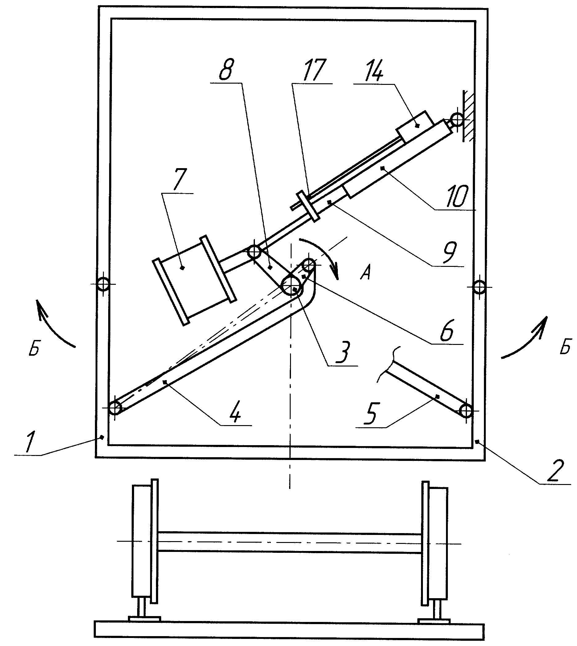
На фиг.1 схематически показан вагон для перевозки торфа, поперечный разрез; на фиг.2 - гидравлическая схема механизма разгрузочного люка.Figure 1 schematically shows a carriage for transporting peat, a cross section; figure 2 is a hydraulic diagram of the mechanism of the discharge hatch.
Вагон для перевозки торфа содержит расположенные друг против друга разгрузочные люки (фиг.1), крышки 1 и 2 которых связаны с продольным поворотно смонтированным валом 3 тягами 4 и 5, шарнирно соединенными с рычагом 6, жестко закрепленным на валу 3. Для наглядности изображения схема устройства на фиг.1The peat carriage contains unloading hatches (Fig. 1) located opposite each other, the covers 1 and 2 of which are connected to the longitudinal rotary mounted shaft 3 by rods 4 and 5, pivotally connected to the lever 6, rigidly mounted on the shaft 3. For illustrative purposes, the diagram device in figure 1
выполнена упрощенно, на ней отсутствует ряд деталей, несущественных для заявленного технического рещения, другие (изображенные на чертеже) детали имеют иную конфигурацию и пропорции по отношению к материально воплощеннрму объекту. Например, на реальном устройстве рычаг 6 выполнен двуплечим, одновременно воздействуя на обе тяги 4 и 5 и т.д.simplified, it lacks a number of details that are not essential for the claimed technical solution, other (shown in the drawing) details have a different configuration and proportion to the materially embodied object. For example, on a real device, the lever 6 is made two-armed, simultaneously acting on both rods 4 and 5, etc.
Привод поворота вала 3 выполнен от пневмоцилиндра 7 двойного действия, шток которого кинематически связан с другим рычагом 8, жестко закрепленном на валу 3.The rotation drive of the shaft 3 is made from a double-acting pneumatic cylinder 7, the rod of which is kinematically connected to another lever 8, rigidly fixed to the shaft 3.
Пневмоприводной вал 3 посредством, например, рычага 8, шарнирно связан со штоком 9 гидроцилиндра 10 двойного действия.The pneumatic drive shaft 3 by means of, for example, a lever 8, is pivotally connected to the rod 9 of the double-acting hydraulic cylinder 10.
Гидросистема устройства (фиг.2) посредством трубопроводов соединяет между собой штоковую 11 и поршневую 12 полости гидроцилиндра 10. В соединительные трубопроводы встроены последовательно гидродроссель 13 и гидрораспределитель 14, параллельно которым смонтирован обратный клапан 15. Гидросистема подключена к расширительному бачку 16. На штоке 9 гидроцилиндра 8 установочно-подвижно смонтирован ползун 17, кинематически связанный с гидрозолотником 14.The hydraulic system of the device (Fig. 2) connects the rod 11 and piston 12 cavities of the hydraulic cylinder 10 through the pipelines. The hydraulic throttle 13 and the hydraulic distributor 14 are connected in series to the connecting pipelines, the check valve 15 is mounted in parallel with it. 8, a slider 17 kinematically connected with a hydroshock 14 is mounted movably mounted.
Устройство работает следующим образом. При подаче воздуха в пневмоцилиндр 7 вал 3 начинает поворачиваться по стрелке «А и, воздействуя через рычаг 6 на тяги 4 и 5, открывает крышки 1 и 2 разгрузочных люков по стрелке «Б. Одновременно щток 9 гидроцилиндра 10 начинает перемещаться вправо, вытесняя рабочую среду (масло) из полости 12 в полость 11. Скорость перемещения штока 9, а следовательно и скорость открывания крышек 1 и 2 разгрузочных люков задается дросселем 13 и может регулироваться. Величина раскрытия разгрузочных люков (угол поворота крышек 1 и 2) задается соответствующей установкой (положением) ползуна 17 на штоке 9: имея кинематическую связь с гидрораспределителем 14, ползун 17 (двигаясь вместе со штоком 9) в соответствующий момент переключает распределитель 14, прекращая истечение масла из полости 12, шток 9 останавливается, а вместе с ним и прекращается поворот вала 3. Для закрывания крышек 1 и 2 воздух подается в противоположную полость пневмоцилиндра 7, вал 3 начинает вращаться в направлении, противоположном стрелке «А, шток 9 гидроцилиндра 10 также начинает перемещаться в противоположном направлении, а масло в гидроцилиндре начинает перетекать из полости 11 в полость 12 6The device operates as follows. When air is supplied to the pneumatic cylinder 7, the shaft 3 starts to turn in the direction of arrow “A and, acting through the lever 6 on the rods 4 and 5, opens the covers 1 and 2 of the discharge hatches in the direction of arrow“ B. At the same time, the rod 9 of the hydraulic cylinder 10 begins to move to the right, displacing the working medium (oil) from the cavity 12 into the cavity 11. The speed of movement of the rod 9, and therefore the opening speed of the covers 1 and 2 of the discharge hatches, is set by the throttle 13 and can be adjusted. The magnitude of the opening of the discharge hatches (angle of rotation of the covers 1 and 2) is set by the corresponding installation (position) of the slider 17 on the rod 9: having kinematic connection with the valve 14, the slider 17 (moving with the rod 9) at the right moment switches the valve 14, stopping the flow of oil from the cavity 12, the rod 9 stops, and with it the rotation of the shaft 3 stops. To close the covers 1 and 2, air is supplied to the opposite cavity of the pneumatic cylinder 7, the shaft 3 starts to rotate in the opposite direction of the arrow “A, w ca. 9 of the hydraulic cylinder 10 also starts to move in the opposite direction, and the oil in the hydraulic cylinder begins to flow from cavity 11 into the cavity 12 June
через обратный клапан 15, минуя запертый гидрораспределитель дроссель 13.through the check valve 15, bypassing the locked directional control valve throttle 13.
Поскольку полости 11 и 12 гидроцилиндра 10 имеют разный объем, то при перетекании масла из одной полости в, другую в трубопроводах гидросистемы образуется или избыток, или недостаток масла. Подключенный к гидросистеме расширительный бачок 16 принимает излишек и пополняет недостаток масла в гидросистеме, возникаюш;ий также и за счет утечек в различных уплотнениях системы, компенсирует изменение объема рабочей жидкости (масла) вследствие температурного расширения (сжатия). 1Since the cavities 11 and 12 of the hydraulic cylinder 10 have a different volume, when the oil flows from one cavity into the other, either an excess or a lack of oil is formed in the pipelines of the hydraulic system. The expansion tank 16 connected to the hydraulic system receives the excess and replenishes the lack of oil in the hydraulic system that occurs; it also, due to leaks in various seals of the system, compensates for the change in the volume of the working fluid (oil) due to thermal expansion (compression). 1
Claims (1)
Priority Applications (1)
| Application Number | Priority Date | Filing Date | Title |
|---|---|---|---|
| RU2003123919/20U RU37056U1 (en) | 2003-07-31 | 2003-07-31 | PEAT CARRIAGE |
Applications Claiming Priority (1)
| Application Number | Priority Date | Filing Date | Title |
|---|---|---|---|
| RU2003123919/20U RU37056U1 (en) | 2003-07-31 | 2003-07-31 | PEAT CARRIAGE |
Publications (1)
| Publication Number | Publication Date |
|---|---|
| RU37056U1 true RU37056U1 (en) | 2004-04-10 |
Family
ID=38037259
Family Applications (1)
| Application Number | Title | Priority Date | Filing Date |
|---|---|---|---|
| RU2003123919/20U RU37056U1 (en) | 2003-07-31 | 2003-07-31 | PEAT CARRIAGE |
Country Status (1)
| Country | Link |
|---|---|
| RU (1) | RU37056U1 (en) |
Cited By (1)
| Publication number | Priority date | Publication date | Assignee | Title |
|---|---|---|---|---|
| WO2024167438A1 (en) * | 2023-02-08 | 2024-08-15 | Николай ДЕРЮГИН | Display board |
-
2003
- 2003-07-31 RU RU2003123919/20U patent/RU37056U1/en active IP Right Revival
Cited By (1)
| Publication number | Priority date | Publication date | Assignee | Title |
|---|---|---|---|---|
| WO2024167438A1 (en) * | 2023-02-08 | 2024-08-15 | Николай ДЕРЮГИН | Display board |
Similar Documents
| Publication | Publication Date | Title |
|---|---|---|
| US9643625B2 (en) | System and method for powered railcar doors | |
| US8915194B2 (en) | Hopper cars with one or more discharge control systems | |
| AU2012214719B2 (en) | Cover system for open top rail cars | |
| US7735426B2 (en) | Hopper cars with one or more discharge control systems | |
| US20200240193A1 (en) | Railroad hopper car body fittings | |
| US9580086B2 (en) | Railcar cover systems | |
| BR102018016305B1 (en) | FRACTIONAL BULK LOADING AND UNLOADING DEVICE. | |
| RU37056U1 (en) | PEAT CARRIAGE | |
| US7934457B2 (en) | Railcar positioning system | |
| US5606916A (en) | Hopper door operating mechanism | |
| US5000358A (en) | Low profile pneumatic outlet | |
| CN204172914U (en) | A kind of self-discharging carriage of railway transport open car | |
| CN214084226U (en) | Special self-discharging formula mine car of single track hanging | |
| CN205344906U (en) | Switching top cap and railway freight car that railway freight car used | |
| RU44294U1 (en) | HOPPER WAGON FOR CARRIAGE OF BULK CARGOES | |
| CN217347802U (en) | Gate type ballast unloading transport vehicle | |
| US20230406365A1 (en) | Automatic discharge sliding door mechanism for railroad hopper cars | |
| RU160086U1 (en) | SELF-UNLOADING DUMP WAGON | |
| CA2964652C (en) | Railroad hopper car body fittings | |
| RU47834U1 (en) | Wagon-Hopper | |
| RU2631760C2 (en) | Car with opening roof of v.v. bodrov structure | |
| RU30330U1 (en) | PLANT FOR UNLOADING BULK CARGOES FROM RAILWAY CARS | |
| CN101279605A (en) | Self-dumping box of closed wagon | |
| CH330705A (en) | Rail freight cars |
Legal Events
| Date | Code | Title | Description |
|---|---|---|---|
| MM1K | Utility model has become invalid (non-payment of fees) |
Effective date: 20050801 |
|
| NF1K | Reinstatement of utility model |
Effective date: 20071120 |