RU2744211C1 - Fiber optical access terminal - Google Patents
Fiber optical access terminal Download PDFInfo
- Publication number
- RU2744211C1 RU2744211C1 RU2019130271A RU2019130271A RU2744211C1 RU 2744211 C1 RU2744211 C1 RU 2744211C1 RU 2019130271 A RU2019130271 A RU 2019130271A RU 2019130271 A RU2019130271 A RU 2019130271A RU 2744211 C1 RU2744211 C1 RU 2744211C1
- Authority
- RU
- Russia
- Prior art keywords
- fiber optic
- node
- box body
- fiber
- access terminal
- Prior art date
Links
- 239000000835 fiber Substances 0.000 title claims abstract description 217
- 230000003287 optical effect Effects 0.000 title claims abstract description 87
- 239000000428 dust Substances 0.000 claims abstract description 10
- 238000005516 engineering process Methods 0.000 abstract description 4
- 230000000694 effects Effects 0.000 abstract 1
- 239000000126 substance Substances 0.000 abstract 1
- 239000013307 optical fiber Substances 0.000 description 35
- 238000011109 contamination Methods 0.000 description 2
- 238000010586 diagram Methods 0.000 description 2
- 230000006870 function Effects 0.000 description 2
- XLYOFNOQVPJJNP-UHFFFAOYSA-N water Substances O XLYOFNOQVPJJNP-UHFFFAOYSA-N 0.000 description 2
- 230000009286 beneficial effect Effects 0.000 description 1
- 238000004891 communication Methods 0.000 description 1
- 238000009434 installation Methods 0.000 description 1
- 239000000463 material Substances 0.000 description 1
- 238000000034 method Methods 0.000 description 1
- 230000004048 modification Effects 0.000 description 1
- 238000012986 modification Methods 0.000 description 1
Images


Classifications
-
- G—PHYSICS
- G02—OPTICS
- G02B—OPTICAL ELEMENTS, SYSTEMS OR APPARATUS
- G02B6/00—Light guides; Structural details of arrangements comprising light guides and other optical elements, e.g. couplings
- G02B6/24—Coupling light guides
- G02B6/36—Mechanical coupling means
- G02B6/38—Mechanical coupling means having fibre to fibre mating means
- G02B6/3807—Dismountable connectors, i.e. comprising plugs
- G02B6/381—Dismountable connectors, i.e. comprising plugs of the ferrule type, e.g. fibre ends embedded in ferrules, connecting a pair of fibres
- G02B6/3825—Dismountable connectors, i.e. comprising plugs of the ferrule type, e.g. fibre ends embedded in ferrules, connecting a pair of fibres with an intermediate part, e.g. adapter, receptacle, linking two plugs
-
- G—PHYSICS
- G02—OPTICS
- G02B—OPTICAL ELEMENTS, SYSTEMS OR APPARATUS
- G02B6/00—Light guides; Structural details of arrangements comprising light guides and other optical elements, e.g. couplings
- G02B6/44—Mechanical structures for providing tensile strength and external protection for fibres, e.g. optical transmission cables
- G02B6/4439—Auxiliary devices
- G02B6/444—Systems or boxes with surplus lengths
- G02B6/4441—Boxes
- G02B6/4446—Cable boxes, e.g. splicing boxes with two or more multi fibre cables
- G02B6/4447—Cable boxes, e.g. splicing boxes with two or more multi fibre cables with divided shells
-
- G—PHYSICS
- G02—OPTICS
- G02B—OPTICAL ELEMENTS, SYSTEMS OR APPARATUS
- G02B6/00—Light guides; Structural details of arrangements comprising light guides and other optical elements, e.g. couplings
- G02B6/46—Processes or apparatus adapted for installing or repairing optical fibres or optical cables
- G02B6/47—Installation in buildings
- G02B6/475—Mechanical aspects of installing cables in ducts or the like for buildings
-
- G—PHYSICS
- G02—OPTICS
- G02B—OPTICAL ELEMENTS, SYSTEMS OR APPARATUS
- G02B6/00—Light guides; Structural details of arrangements comprising light guides and other optical elements, e.g. couplings
- G02B6/24—Coupling light guides
- G02B6/36—Mechanical coupling means
- G02B6/38—Mechanical coupling means having fibre to fibre mating means
- G02B6/3807—Dismountable connectors, i.e. comprising plugs
- G02B6/3833—Details of mounting fibres in ferrules; Assembly methods; Manufacture
- G02B6/3847—Details of mounting fibres in ferrules; Assembly methods; Manufacture with means preventing fibre end damage, e.g. recessed fibre surfaces
- G02B6/3849—Details of mounting fibres in ferrules; Assembly methods; Manufacture with means preventing fibre end damage, e.g. recessed fibre surfaces using mechanical protective elements, e.g. caps, hoods, sealing membranes
Landscapes
- Physics & Mathematics (AREA)
- General Physics & Mathematics (AREA)
- Optics & Photonics (AREA)
- Engineering & Computer Science (AREA)
- Civil Engineering (AREA)
- Structural Engineering (AREA)
- Mechanical Coupling Of Light Guides (AREA)
- Light Guides In General And Applications Therefor (AREA)
Abstract
Description
Область техники, к которой относится изобретениеThe technical field to which the invention relates
Настоящее изобретение относится к области волоконно-оптических технологий, в частности к волоконно-оптическому терминалу доступа.The present invention relates to the field of fiber optic technology, in particular to a fiber optic access terminal.
Уровень техникиState of the art
С развитием волоконно-оптических технологий становится популярным применение в связи оптических кабелей. Например, все большее количество пользователей используют оптоволоконный широкополосный доступ к сети Интернет. Пользователь может провести оптическое волокно в помещении через волоконно-оптический терминал доступа (Fibre Access Terminal, FAT).With the development of fiber optic technology, the use of optical cables in communication is becoming popular. For example, more and more users are using fiber-optic broadband Internet access. The user can run the optical fiber indoors through the Fiber Access Terminal (FAT).
В частности, FAT включает в себя такие компоненты, как коробчатый корпус и волоконно-оптический адаптер. Коробчатый корпус имеет вход для оптического кабеля и выход для оптического кабеля (причем оптический кабель обычно включает в себя множество оптических волокон). Одно оптическое волокно оптического кабеля через входное отверстие для оптического кабеля может быть подключено к одному концу волоконно-оптического адаптера с помощью волоконно-оптического соединителя (когда FAT имеет множество волоконно-оптических адаптеров, один конец каждого волоконно-оптического адаптера может быть подключен к одному оптическому волокну оптического кабеля через входное отверстие для оптического кабеля). Другой конец волоконно-оптического адаптера может быть подключен к волоконно-оптическому кабелю, соединенному с волоконно-оптическим соединителем (оптическое волокно может упоминаться как абонентское волокно), а оптический кабель, включающий в себя оставшееся, другое оптическое волокно, может быть выведен из выходного отверстия для оптического кабеля. Волоконно-оптический адаптер и волоконно-оптический соединитель выполняют функцию соединения двух оптических волокон. Когда пользователь намеревается подключиться к широкополосному доступу, предоставляемому по волоконно-оптическому кабелю, оптическое волокно, подключенное к волоконно-оптическому соединителю, может быть подключено к другому концу волоконно-оптического адаптера с помощью волоконно-оптического соединителя, чтобы провести оптическое волокно в помещении. В настоящее время количество волоконно-оптических адаптеров, содержащихся в FAT, является фиксированным. В частности, фиксированным является количество домохозяйств, к которым FAT может направлять оптическое волокно. Сотрудник может выбрать FAT с соответствующим количеством волоконно-оптических адаптеров на основании количества домохозяйств, которые в настоящее время подключены к широкополосному доступу, предоставляемому по волоконно-оптическому кабелю, и может разместить FAT в коридорном пространстве помещения или в другом месте.Specifically, FAT includes components such as a box housing and a fiber optic adapter. The box-shaped housing has an optical cable inlet and an optical cable outlet (an optical cable usually includes a plurality of optical fibers). One optical fiber of an optical cable through the optical cable entry hole can be connected to one end of the fiber optic adapter with a fiber optic connector (when the FAT has multiple fiber optic adapters, one end of each fiber optic adapter can be connected to one fiber optic fiber of the optical cable through the optical cable entry hole). The other end of the fiber optic adapter can be connected to a fiber optic cable connected to the fiber optic connector (the optical fiber can be referred to as subscriber fiber), and the optical cable including the remaining, other optical fiber can be routed out of the outlet. for optical cable. A fiber optic adapter and a fiber optic coupler have the function of connecting two optical fibers. When a user intends to connect to a broadband access provided over a fiber optic cable, the optical fiber connected to the fiber optic connector can be connected to the other end of the fiber optic adapter using the fiber optic connector to conduct the optical fiber indoors. Currently, the number of fiber optic adapters contained in the FAT is fixed. In particular, the number of households to which FAT can send optical fiber is fixed. An employee can select a FAT with the appropriate number of fiber optic adapters based on the number of households that are currently connected to fiber broadband and can place the FAT in the corridor space of the room or elsewhere.
В процессе создания настоящего изобретения было обнаружено, что необходимо решить по меньшей мере описанную ниже техническую проблему предшествующего уровня техники.In the process of making the present invention, it has been found that it is necessary to solve at least the following technical problem of the prior art.
После установки FAT, на основании текущего количества домашних хозяйств, в случае, когда дополнительный пользователь подключается к широкополосному доступу, предоставляемому по волоконно-оптическому кабелю, поскольку количество волоконно-оптических адаптеров при первоначально установленном FAT является недостаточным, сотруднику обычно необходимо удалить первоначально установленный FAT и установить FAT с количеством волоконно-оптических адаптеров, соответствующим текущему количеству домохозяйств. Операция является относительно трудозатратой. Следовательно, эффективность работы является относительно низкой.After installing the FAT, based on the current number of households, in the event that an additional user connects to the broadband access provided by the fiber optic cable, because the number of fiber optic adapters is not enough when the FAT is initially installed, the employee usually needs to remove the originally installed FAT and install FAT with the number of fiber optic adapters corresponding to the current number of households. The operation is relatively labor intensive. Consequently, the work efficiency is relatively low.
Раскрытие сущности изобретенияDisclosure of the essence of the invention
Для повышения эффективности работы варианты осуществления настоящего изобретения предоставляют волоконно-оптический терминал доступа. Техническое решение заключается в следующем.To improve operational efficiency, embodiments of the present invention provide an optical fiber access terminal. The technical solution is as follows.
Предусмотрен волоконно-оптический терминал доступа. Волоконно-оптический терминал доступа может включать в себя первый узел и второй узел. Первый узел может включать в себя первый коробчатый корпус и волоконно-оптический адаптер. Второй узел может включать в себя второй коробчатый корпус, оптический разветвитель, волоконно-оптический соединитель и множество волоконно-оптических адаптеров. Волоконно-оптический адаптер первого узла может быть расположен снаружи первого коробчатого корпуса, при этом первый коробчатый корпус может иметь входное отверстие для оптического кабеля и выходное отверстие для оптического кабеля. Оптический разветвитель может быть расположен внутри второго коробчатого корпуса, при этом волоконно-оптический соединитель и множество волоконно-оптических адаптеров второго узла расположены снаружи второго коробчатого корпуса. Первый конец волоконно-оптического соединителя разъемно соединен с волоконно-оптическим адаптером первого узла, а второй конец волоконно-оптического соединителя соединен с входным портом оптического разветвителя, причем каждый выходной порт оптического разветвителя соединен с одним волоконно-оптическим адаптером второго узла.A fiber optic access terminal is provided. The fiber optic access terminal may include a first node and a second node. The first assembly may include a first box body and a fiber optic adapter. The second assembly may include a second box body, an optical splitter, a fiber optic connector, and a plurality of fiber optic adapters. The fiber optic adapter of the first node may be located outside the first box body, and the first box body may have an optical cable inlet and an optical cable outlet. The optical splitter may be located inside the second box body, with the fiber optic connector and the plurality of fiber optic adapters of the second node located outside the second box body. The first end of the fiber optic connector is detachably connected to the fiber optic adapter of the first node, and the second end of the fiber optic connector is connected to the input port of the optical splitter, each output port of the optical splitter being connected to one fiber optic adapter of the second node.
В решении, показанном в вариантах осуществления настоящего изобретения, волоконно-оптический терминал доступа может включать в себя два узла (в частности, первый узел и второй узел). Первый коробчатый корпус первого узла может иметь входное отверстие для оптического кабеля и выходное отверстие для оптического кабеля. Второй узел может быть разъемно соединен с первым узлом. Таким образом, после того, как волоконно-оптический терминал доступа установлен на основании текущего количества домашних хозяйств, когда дополнительный пользователь подключается к широкополосному доступу, предоставляемому по волоконно-оптическому кабелю, сотрудник может заменить второй узел ранее установленного волоконно-оптического терминала доступа на второй узел, включающий в себя большее количество волоконно-оптических адаптеров, при этом сотрудник не должен демонтировать первый узел, поэтому может быть повышена эффективность работы.In the solution shown in the embodiments of the present invention, the fiber optic access terminal may include two nodes (specifically, a first node and a second node). The first box body of the first assembly may have an optical cable inlet and an optical cable outlet. The second node can be detachably connected to the first node. Thus, after the fiber optic access terminal is installed based on the current number of households, when an additional user connects to the broadband access provided over the fiber optic cable, the employee can replace the second node of the previously installed fiber optic access terminal with a second node. that includes more fiber optic adapters, and the employee does not have to dismantle the first node, so work efficiency can be increased.
В возможном варианте осуществления изобретения второй узел дополнительно включает в себя множество пылезащитных колпачков, причем каждый из множества пылезащитных колпачков расположен на одном волоконно-оптическом адаптере второго узла.In an exemplary embodiment, the second assembly further includes a plurality of dust caps, each of the plurality of dust caps disposed on a single fiber optic adapter of the second assembly.
Таким образом, когда волоконно-оптический адаптер не используется, волоконно-оптический адаптер может быть защищен от загрязнения.Thus, when the fiber optic adapter is not in use, the fiber optic adapter can be protected from contamination.
В возможном варианте осуществления изобретения первый коробчатый корпус имеет направляющий паз, а второй коробчатый корпус содержит выступ, при этом выступ вставлен в направляющий паз.In an exemplary embodiment of the invention, the first box body has a guide groove and the second box body comprises a projection, the projection being inserted into the guide groove.
Таким образом, когда сотрудник соединяет первый узел со вторым узлом, соединение между волоконно-оптическим адаптером и волоконно-оптическим соединителем может быть реализовано точнее и быстрее.Thus, when an employee connects the first node to the second node, the connection between the fiber optic adapter and the fiber optic connector can be realized more accurately and faster.
В возможном варианте осуществления изобретения первый узел дополнительно включает в себя первое крепежное средство, при этом первый коробчатый корпус включает в себя верхнюю часть коробчатого корпуса и нижнюю часть коробчатого корпуса. Верхняя часть коробчатого корпуса и нижняя часть коробчатого корпуса могут быть соединены с помощью первого крепежного средства.In an exemplary embodiment, the first assembly further includes a first securing means, the first box body including an upper box body and a lower box body. The upper part of the box body and the lower part of the box body can be connected with the first fastening means.
В возможном варианте осуществления изобретения первое крепежное средство включает в себя множество винтов, при этом верхняя часть коробчатого корпуса и нижняя часть коробчатого корпуса соединены с помощью множества винтов.In an exemplary embodiment of the invention, the first fastening means includes a plurality of screws, and the top of the box body and the bottom of the box body are connected by a plurality of screws.
В возможном варианте осуществления изобретения волоконно-оптический терминал доступа дополнительно включает в себя второе крепежное средство. Первый узел и второй узел соединены с помощью второго крепежного средства.In an exemplary embodiment of the invention, the fiber optic access terminal further includes a second fastening means. The first assembly and the second assembly are connected by means of a second fastening means.
В возможном варианте осуществления изобретения второй крепежный элемент включает в себя множество винтов. Первый узел и второй узел соединены с помощью множества винтов.In an exemplary embodiment of the invention, the second fastener includes a plurality of screws. The first node and the second node are connected with a plurality of screws.
В возможном варианте осуществления изобретения имеются один или более волоконно-оптических адаптеров первого узла. Количество волоконно-оптических соединителей и количество оптических разветвителей соответствуют количеству волоконно-оптических адаптеров первого узла. Первый конец каждого волоконно-оптического соединителя разъемно соединен с одним волоконно-оптическим адаптером первого узла, а второй конец каждого волоконно-оптического соединителя соединен с входным портом одного оптического разветвителя.In an exemplary embodiment of the invention, one or more first node fiber optic adapters are provided. The number of fiber optic connectors and the number of optical splitters correspond to the number of fiber optic adapters of the first node. The first end of each fiber optic connector is detachably connected to one fiber optic adapter of the first node, and the second end of each fiber optic connector is connected to an input port of one optical splitter.
В возможном варианте осуществления изобретения волоконно-оптический адаптер первого узла и множество волоконно-оптических адаптеров второго узла являются наружными волоконно-оптическими адаптерами.In an exemplary embodiment, the first node's fiber optic adapter and the second node's plurality of second node's fiber optic adapters are outdoor fiber optic adapters.
В возможном варианте осуществления изобретения волоконно-оптический адаптер первого узла расположен внизу первого коробчатого корпуса, при этом волоконно-оптический соединитель расположен вверху второго коробчатого корпуса, причем множество волоконно-оптических адаптеров второго узла расположено снизу второго коробчатого корпуса.In an exemplary embodiment, the first node's fiber optic adapter is located at the bottom of the first box body, the fiber optic connector is located at the top of the second box body, with a plurality of second node's fiber optic adapters located below the second box body.
Таким образом, после подключения волоконно-оптический терминал доступа может иметь повышенную водонепроницаемость, поэтому период эксплуатации волоконно-оптического терминала доступа может быть увеличен.Thus, once connected, the fiber optic access terminal can have increased water resistance, so the life of the fiber optic access terminal can be extended.
Полезными эффектами технического решения, предоставленного в вариантах осуществления настоящего изобретения, являются следующие эффекты.The beneficial effects of the technical solution provided in the embodiments of the present invention are as follows.
В вариантах осуществления настоящего изобретения волоконно-оптический терминал доступа может включать в себя первый узел и второй узел. Первый узел может включать в себя первый коробчатый корпус и волоконно-оптический адаптер. Второй узел может включать в себя второй коробчатый корпус, оптический разветвитель, волоконно-оптический соединитель и множество волоконно-оптических адаптеров. Волоконно-оптический адаптер первого узла может быть расположен снаружи первого коробчатого корпуса, при этом первый коробчатый корпус может иметь входное отверстие для оптического кабеля и выходное отверстие для оптического кабеля. Оптический разветвитель может быть расположен внутри второго коробчатого корпуса, при этом волоконно-оптический соединитель и множество волоконно-оптических адаптеров второго узла расположены снаружи второго коробчатого корпуса. Первый конец волоконно-оптического соединителя разъемно соединен с волоконно-оптическим адаптером первого узла, а второй конец волоконно-оптического соединителя соединен с входным портом оптического разветвителя, причем каждый выходной порт оптического разветвителя соединен с одним волоконно-оптическим адаптером второго узла. Таким образом, после того, как волоконно-оптический терминал доступа установлен с учетом текущего количества домохозяйств, когда дополнительный пользователь подключается к широкополосному доступу, предоставляемому по волоконно-оптическому кабелю, сотрудник может заменить второй узел ранее установленного волоконно-оптического терминала доступа на второй узел, включающий в себя большее количество волоконно-оптических адаптеров, при этом сотруднику не придется демонтировать первый узел, поэтому эффективность работы может быть повышена.In embodiments of the present invention, an optical fiber access terminal may include a first node and a second node. The first assembly may include a first box body and a fiber optic adapter. The second assembly may include a second box body, an optical splitter, a fiber optic connector, and a plurality of fiber optic adapters. The fiber optic adapter of the first node may be located outside the first box body, and the first box body may have an optical cable inlet and an optical cable outlet. The optical splitter may be located inside the second box body, with the fiber optic connector and the plurality of fiber optic adapters of the second node located outside the second box body. The first end of the fiber optic connector is detachably connected to the fiber optic adapter of the first node, and the second end of the fiber optic connector is connected to the input port of the optical splitter, each output port of the optical splitter being connected to one fiber optic adapter of the second node. In this way, after the fiber optic access terminal is set based on the current number of households, when an additional user connects to the broadband access provided over the fiber optic cable, the employee can replace the second node of the previously installed fiber optic access terminal with the second node. including more fiber-optic adapters, while the employee does not have to dismantle the first node, so work efficiency can be increased.
Краткое описание чертежейBrief Description of Drawings
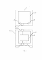
На фиг. 1 показана структурная схема волоконно-оптического терминала доступа в соответствии с вариантом осуществления настоящего изобретения;FIG. 1 is a block diagram of an optical fiber access terminal according to an embodiment of the present invention;
на фиг. 2 – волоконно-оптический адаптер и волоконно-оптический соединитель в соответствии с вариантом осуществления настоящего изобретения;in fig. 2 illustrates a fiber optic adapter and a fiber optic connector in accordance with an embodiment of the present invention;
на фиг. 3 – волоконно-оптический терминал доступа в соответствии с вариантом осуществления настоящего изобретения;in fig. 3 illustrates a fiber optic access terminal in accordance with an embodiment of the present invention;
на фиг. 4 – второй узел в соответствии с вариантом осуществления настоящего изобретения;in fig. 4 shows a second node in accordance with an embodiment of the present invention;
на фиг. 5 – волоконно-оптический терминал доступа в соответствии с вариантом осуществления настоящего изобретения;in fig. 5 illustrates a fiber optic access terminal in accordance with an embodiment of the present invention;
на фиг. 6 – структурная схема волоконно-оптического терминала доступа в соответствии с вариантом осуществления настоящего изобретения;in fig. 6 is a block diagram of a fiber optic access terminal according to an embodiment of the present invention;
на фиг. 7 – первый узел в соответствии с вариантом осуществления настоящего изобретения; иin fig. 7 shows a first node in accordance with an embodiment of the present invention; and
на фиг. 8 – волоконно-оптический терминал доступа в соответствии с вариантом осуществления настоящего изобретения.in fig. 8 illustrates a fiber optic access terminal in accordance with an embodiment of the present invention.
Ссылочные позиции:Reference positions:
1. Первый узел 1. First node
11. Первый коробчатый корпус 11. First box body
111. Входное отверстие для оптического кабеля111. Inlet for optical cable
112. Выходное отверстие для оптического кабеля112. Exit hole for optical cable
113. Направляющий паз 113. Guide groove
114. Верхняя часть коробчатого корпуса 114. The upper part of the box body
115. Нижняя часть коробчатого корпуса 115. The lower part of the box-shaped body
12. Волоконно-оптический адаптер первого узла12. First node fiber optic adapter
13. Первое крепежное средство 13. First fastener
131. Винт первого крепежного средства131. Screw of the first fastener
2. Второй узел 2. Second node
21. Второй коробчатый корпус 21. Second box body
211. Выступ 211. Ledge
22. Оптический разветвитель22. Optical splitter
23. Волоконно-оптический соединитель 23. Fiber optic connector
24. Волоконно-оптический адаптер второго узла24. Fiber optic adapter of the second node
25. Пылезащитный колпачок 25. Dust cap
3. Второе крепежное средство3. Second fastener
31. Винт второго крепежного средства31. Screw of the second fastener
Осуществление изобретенияImplementation of the invention
На фиг. 1 изображен волоконно-оптический терминал доступа в соответствии с вариантом осуществления настоящего изобретения. Как показано на фиг. 1, волоконно-оптический терминал доступа включает в себя первый узел 1 и второй узел 2. Первый узел 1 включает в себя первый коробчатый корпус 11 и волоконно-оптический адаптер 12. Второй узел 2 включает в себя второй коробчатый корпус 21, оптический разветвитель 22, волоконно-оптический соединитель 23 и множество волоконно-оптических адаптеров 24. Волоконно-оптический адаптер 12 первого узла 1 расположен снаружи первого коробчатого корпуса 11, при этом первый коробчатый корпус 11 имеет входное отверстие 111 для оптического кабеля и выходное отверстие 112 для оптического кабеля. Оптический разветвитель 22 расположен внутри второго коробчатого корпуса 21, а волоконно-оптический соединитель 23 и множество волоконно-оптических адаптеров 24 второго узла 2 расположены снаружи второго коробчатого корпуса 21. Первый конец волоконно-оптического соединителя 23 разъемно соединен с волоконно-оптическим адаптером 12 первого узла 1, а второй конец волоконно-оптического соединителя 23 соединен с входным портом оптического разветвителя 22, при этом каждый выходной порт оптического разветвителя 22 подключен к одному волоконно-оптическому адаптеру 24 второго узла 2.FIG. 1 depicts a fiber optic access terminal in accordance with an embodiment of the present invention. As shown in FIG. 1, an optical fiber access terminal includes a
Во время работы волоконно-оптический терминал доступа может включать в себя первый узел 1 и второй узел 2. Первый узел 1 может работать независимо или может работать совместно со вторым узлом 2. Первый узел 1 может включать в себя первый коробчатый корпус 11 и волоконно-оптический адаптер 12, причем волоконно-оптический адаптер 12 может быть расположен снаружи первого коробчатого корпуса 11. Первый коробчатый корпус 11 может быть дополнительно иметь входное отверстие 111 для оптического кабеля и выходное отверстие 112 для оптического кабеля. При подключении первого узла 1 оптический кабель может быть введен в первый коробчатый корпус 11 через входное отверстие 111 для оптического кабеля и может быть выведен из первого коробчатого корпуса 11 через выходное отверстие 112 для оптического кабеля. Материал первого коробчатого корпуса 11 может быть пластиком.In operation, the fiber optic access terminal may include a
Первый узел 1 может дополнительно включать в себя компонент для сращивания оптического волокна и оптическую вилку, которая имеет предварительно изготовленный волоконно-оптический соединитель. Компонент для сращивания оптического волокна может выполнять функцию хранения оптического кабеля и защиты оптического волокна. Компонент для сращивания оптического волокна и оптическая вилка, которая имеет предварительно изготовленный волоконно-оптический соединитель, расположены внутри первого коробчатого корпуса 11, при этом другой конец оптической вилки соединен с одним концом волоконно-оптического адаптера 12 с помощью предварительно изготовленного волоконно-оптического соединителя. При подключении первого узла 1 сотрудник может срастить одно оптическое волокно в оптическом кабеле, входящем во входное отверстие 111 оптического кабеля, с оптической вилкой. Когда пользователь намеревается получить широкополосный доступ, предоставляемый по оптическому кабелю, оптическое волокно, имеющее предварительно изготовленный волоконно-оптический соединитель (оптическое волокно может называться абонентским волокном), может быть подключено к другому концу волоконно-оптического адаптера 12 с помощью волоконно-оптического соединителя, чтобы провести его в помещении. Другими словами, при подключении первого узла 1 один конец волоконно-оптического адаптера 12 может быть соединен с предварительно изготовленным волоконно-оптическим соединителем оптической вилки, расположенной внутри первого коробчатого корпуса 11, а другим концом может быть подключен к абонентскому волокну с помощью волоконно-оптического соединителя.The
Второй узел 2 может включать в себя второй коробчатый корпус 21, оптический разветвитель 22, волоконно-оптический соединитель 23 и множество волоконно-оптических адаптеров 24. Оптический разветвитель 22 может быть расположен внутри второго коробчатого корпуса 21. Волоконно-оптический соединитель 23 и множество волоконно-оптических адаптеров 24 второго узла 2 могут быть расположены снаружи второго коробчатого корпуса 21. Второй конец волоконно-оптического соединителя 23 соединен с входным портом оптического разветвителя 22 (причем второй конец волоконно-оптического соединителя 23 соединен с входным портом оптического разветвителя 22 с помощью оптического волокна). Каждый выходной порт оптического разветвителя 22 подключен к одному волоконно-оптическому адаптеру 24 второго узла 2 (причем каждый выходной порт оптического разветвителя 22 может быть подключен к оптическому волокну, имеющему предварительно изготовленный волоконно-оптический соединитель, а именно: каждый выходной порт оптического разветвителя 22 может быть подключен к одному волоконно-оптическому адаптеру 24 второго узла 2 с помощью волоконно-оптического соединителя выходного порта). Второй узел 2 может работать совместно с первым узлом 1. Когда второй узел 2 работает совместно с первым узлом 1, первый конец волоконно-оптического соединителя 23 второго узла 2 может быть разъемно соединен с волоконно-оптическим адаптером 12 первого узла 1. Каждый волоконно-оптический адаптер 24 может быть подключен к одному абонентскому волокну. Пример волоконно-оптического адаптера 12 и волоконно-оптического соединителя 23 показан на фиг. 2. Поскольку второй узел 2 включает в себя множество волоконно-оптических адаптеров 24, емкость волоконно-оптического терминала доступа может быть изменена путем замены второго узла 2 на второй узел 2, включающий в себя другое количество волоконно-оптических адаптеров 12 (то есть изменения количества волоконно-оптических адаптеров волоконно-оптического терминала доступа). Таким образом, после размещения FAT на основе текущего количества домашних хозяйств, когда дополнительный пользователь подключается к широкополосному доступу, предоставляемому по волоконно-оптическому кабелю, сотрудник может заменить исходный второй узел на второй узел, включающий в себя большее количество волоконно-оптических адаптеров, для увеличения количества волоконно-оптических адаптеров FAT. Сотруднику не нужно демонтировать первый узел и повторно устанавливать FAT с количеством волоконно-оптических адаптеров, соответствующих текущему количеству домохозяйств, поэтому может быть повышена эффективность работы.The
Кроме того, первый коробчатый корпус 11 может иметь скос. Соответственно, второй коробчатый корпус 21 может иметь скос, ответный скосу первого коробчатого корпуса 11. Первый узел 1 и второй узел 2, которые соединены вместе, показаны на фиг. 3.In addition, the
Необязательно, второй узел может дополнительно включать в себя множество пылезащитных колпачков 25. Как показано на фиг. 4, количество пылезащитных колпачков 25 может соответствовать количеству волоконно-оптических адаптеров 24. Каждый из множества пылезащитных колпачков 25 может быть расположен на одном волоконно-оптическом адаптере 24 второго узла 2. Таким образом, когда волоконно-оптический адаптер не используется, волоконно-оптический адаптер может быть защищен от загрязнения.Optionally, the second assembly may further include a plurality of dust caps 25. As shown in FIG. 4, the number of dust caps 25 may correspond to the number of
Необязательно, как показано на фиг. 5, первый коробчатый корпус 11 может иметь направляющий паз 113, а второй коробчатый корпус 21 – выступ 211, при этом выступ 211 входит в направляющий паз 113.Optionally, as shown in FIG. 5, the
Чтобы во время установки помочь сотруднику соединить волоконно-оптический соединитель 23 второго узла 2 с волоконно-оптическим адаптером 12 первого узла 1, первый коробчатый корпус 11 может иметь направляющий паз 113, а второй коробчатый корпус 21 – выступ. Таким образом, выступ 211 может входить в направляющий паз 113 и обеспечивать предварительное позиционирование. Это может позволить сотруднику точнее и быстрее соединить волоконно-оптический соединитель 23 с волоконно-оптическим адаптером 12.To assist an employee during installation to connect the
Необязательно, первый узел 1 дополнительно включает в себя первое крепежное средство 13, а первый коробчатый корпус включает в себя верхнюю часть 114 коробчатого корпуса и нижнюю часть 115 коробчатого корпуса. Верхняя часть 114 коробчатого корпуса и нижняя часть 115 коробчатого корпуса могут быть соединены с помощью первого крепежного средства 13.Optionally, the
Первый коробчатый корпус первого узла 1 может быть образован путем соединения верхней части 114 коробчатого корпуса с нижней частью 115 коробчатого корпуса с помощью первого крепежного средства 13, при этом на фиг. 6 показан вид сбоку первого узла 1.The first box body of the
Необязательно, первое крепежное средство 13 может включать в себя множество винтов 131, при этом верхняя часть 114 коробчатого корпуса и нижняя часть 115 коробчатого корпуса могут быть соединены с помощью множества винтов 131.Optionally, the
Первое крепежное средство 13 может включать в себя множество винтов 131, например четыре винта 131. Как показано на фиг. 7, каждая из верхней части 114 коробчатого корпуса и нижней части 115 коробчатого корпуса может иметь резьбы, соответствующие множеству винтов 131. Таким образом, верхняя часть 114 коробчатого корпуса и нижняя часть 115 коробчатого корпуса могут быть соединены с помощью винтов 131 и резьб, соответствующих винтам 131. При подключении волоконно-оптического терминала сотруднику удобно открыть первый коробчатый корпус 11 и затем соединить одно оптическое волокно в оптическом кабеле с оптической вилкой. Кроме того, когда первый коробчатый корпус 11 имеет скос и второй коробчатый корпус 21 имеет скос, ответный скосу первого коробчатого корпуса 11, во втором коробчатом корпусе 21 могут быть выполнены сквозные отверстия тех в местах, которые соответствуют двум винтам, расположенным снизу первого коробчатого корпуса 11.The first fastening means 13 may include a plurality of
Кроме того, второй коробчатый корпус 21 также включает в себя верхнюю часть коробчатого корпуса и нижнюю часть коробчатого корпуса. Верхняя часть коробчатого корпуса и нижняя часть коробчатого корпуса второго корпуса 21 могут быть соединены так же, как и в первом коробчатом корпусе 11, или могут быть соединены ультразвуковой сваркой.In addition, the
Необязательно, волоконно-оптический терминал доступа дополнительно включает в себя второе крепежное средство 3, при этом первый узел 1 и второй узел 2 соединены с помощью второго крепежного средства.Optionally, the fiber optic access terminal further includes a second fastening means 3, wherein the
Необязательно, как показано на фиг. 8, второе крепежное средство 3 включает в себя множество винтов 31, при этом первый узел 1 и второй узел 2 соединены с помощью множества винтов 31.Optionally, as shown in FIG. 8, the second fastening means 3 includes a plurality of
Второе крепежное средство может включать в себя множество винтов 31, например два винта. Первый коробчатый корпус 11 и второй коробчатый корпус 21 могут иметь резьбы, соответствующие винтам 31. Как показано на фиг. 8, первый узел 1 и второй узел могут быть соединены с помощью винтов и резьб, соответствующих винтам 31.The second fastening means may include a plurality of
Необязательно, первый узел 1 содержит один или более волоконно-оптических адаптеров 12. Количество волоконно-оптических соединителей 23 и количество оптических разветвителей 22 соответствуют количеству волоконно-оптических адаптеров 12 первого узла 1. Первый конец каждого волоконно-оптического соединителя 23 разъемно соединен с одним волоконно-оптическим адаптером 12 первого узла 1, а второй конец каждого волоконно-оптического соединителя 23 соединен с входным портом одного оптического разветвителя 22.Optionally, the
Первый узел 1 может включать в себя один волоконно-оптический адаптер или может включать в себя множество волоконно-оптических адаптеров (например, может быть два волоконно-оптических адаптера). Соответственно, количество волоконно-оптических соединителей 23 и количество оптических разветвителей 22 соответствуют количеству волоконно-оптических адаптеров 12 первого узла 1. А именно, когда первый узел включает в себя один волоконно-оптический адаптер, второй узел может включать в себя один волоконно-оптический соединитель и один оптический разветвитель, а когда первый узел 1 включает в себя множество волоконно-оптических адаптеров, второй узел может включать в себя множество волоконно-оптических соединителей и множество оптических разветвителей. Первый конец каждого волоконно-оптического соединителя 23 разъемно соединен с одним волоконно-оптическим адаптером 12 первого узла, а второй конец каждого волоконно-оптического соединителя 23 соединен с входным портом одного оптического разветвителя 22.The
Необязательно, волоконно-оптический адаптер 12 первого узла 1 и множество волоконно-оптических адаптеров 24 второго узла 2 могут быть наружными волоконно-оптическими адаптерами.Optionally, the
Необязательно, волоконно-оптический адаптер 12 первого узла 1 может быть расположен снизу первого коробчатого корпуса 11. Волоконно-оптический соединитель 23 может быть расположен сверху второго коробчатого корпуса 21, при этом множество волоконно-оптических адаптеров 24 второго узла 2 могут быть расположены снизу второго коробчатого корпуса 21.Optionally, the
Таким образом, после подключения волоконно-оптический терминал доступа может иметь повышенную водонепроницаемость, поэтому период эксплуатации волоконно-оптического терминала доступа может быть увеличен.Thus, once connected, the fiber optic access terminal can have increased water resistance, so the life of the fiber optic access terminal can be extended.
В вариантах осуществления настоящего изобретения волоконно-оптический терминал доступа может включать в себя первый узел и второй узел. Первый узел может включать в себя первый коробчатый корпус и волоконно-оптический адаптер. Второй узел может включать в себя второй коробчатый корпус, оптический разветвитель, волоконно-оптический соединитель и множество волоконно-оптических адаптеров. Волоконно-оптический адаптер первого узла может быть расположен снаружи первого коробчатого корпуса, причем первый коробчатый корпус может иметь входное отверстие для оптического кабеля и выходное отверстие для оптического кабеля. Оптический разветвитель может быть расположен внутри второго коробчатого корпуса, при этом волоконно-оптический соединитель и множество волоконно-оптических адаптеров второго узла расположены снаружи второго коробчатого корпуса. Первый конец волоконно-оптического соединителя разъемно соединен с волоконно-оптическим адаптером первого узла, а второй конец волоконно-оптического соединителя соединен с входным портом оптического разветвителя, причем каждый выходной порт оптического разветвителя соединен с одним волоконно-оптическим адаптером второго узла. Таким образом, после того, как волоконно-оптический терминал доступа установлен на основе текущего количества домохозяйств, когда дополнительный пользователь подключается к широкополосному доступу, предоставляемому по оптоволокну, сотрудник может заменить второй узел ранее установленного волоконно-оптического терминала доступа на второй узел, включающий в себя большее количество волоконно-оптических адаптеров, при этом сотруднику не нужно демонтировать первый узел, повышая тем самым эффективность работы.In embodiments of the present invention, an optical fiber access terminal may include a first node and a second node. The first assembly may include a first box body and a fiber optic adapter. The second assembly may include a second box body, an optical splitter, a fiber optic connector, and a plurality of fiber optic adapters. The fiber optic adapter of the first node may be located outside the first box body, the first box body may have an optical cable inlet and an optical cable outlet. The optical splitter may be located inside the second box body, with the fiber optic connector and the plurality of fiber optic adapters of the second node located outside the second box body. The first end of the fiber optic connector is detachably connected to the fiber optic adapter of the first node, and the second end of the fiber optic connector is connected to the input port of the optical splitter, each output port of the optical splitter being connected to one fiber optic adapter of the second node. Thus, after the fiber optic access terminal is set based on the current number of households, when an additional user connects to the broadband access provided over the fiber, the employee can replace the second node of the previously installed fiber optic access terminal with a second node including more fiber optic adapters, while the employee does not need to dismantle the first node, thereby increasing work efficiency.
Специалист в данной области техники может понять, что все или некоторые из этапов вариантов осуществления могут быть реализованы посредством аппаратного обеспечения или программы, инструктирующей соответствующее аппаратное обеспечение. Программа может храниться на машиночитаемом носителе информации. Носитель информации может включать в себя постоянное запоминающее устройство, магнитный диск или оптический диск.A person skilled in the art can understand that all or some of the steps of the embodiments may be implemented by hardware or a program instructing the corresponding hardware. The program can be stored on a computer-readable storage medium. The storage medium may include read-only memory, magnetic disk, or optical disk.
Приведенное выше описание относится лишь к одному варианту осуществления настоящего изобретения, но не предназначено для ограничения настоящего изобретения. Любые модификация, эквивалентная замена или улучшение, сделанные без отклонения от принципа настоящего изобретения, должны находиться в рамках объема защиты настоящего изобретения.The above description refers only to one embodiment of the present invention, but is not intended to limit the present invention. Any modification, equivalent replacement or improvement made without deviating from the principle of the present invention should be within the protection scope of the present invention.
Claims (18)
Applications Claiming Priority (1)
| Application Number | Priority Date | Filing Date | Title |
|---|---|---|---|
| PCT/CN2017/075182 WO2018157285A1 (en) | 2017-02-28 | 2017-02-28 | Fibre access terminal |
Publications (1)
| Publication Number | Publication Date |
|---|---|
| RU2744211C1 true RU2744211C1 (en) | 2021-03-03 |
Family
ID=63369614
Family Applications (1)
| Application Number | Title | Priority Date | Filing Date |
|---|---|---|---|
| RU2019130271A RU2744211C1 (en) | 2017-02-28 | 2017-02-28 | Fiber optical access terminal |
Country Status (8)
| Country | Link |
|---|---|
| US (1) | US11029474B2 (en) |
| EP (1) | EP3575839B1 (en) |
| JP (1) | JP6910456B2 (en) |
| KR (1) | KR102314593B1 (en) |
| CN (1) | CN110192135A (en) |
| CA (1) | CA3053676C (en) |
| RU (1) | RU2744211C1 (en) |
| WO (1) | WO2018157285A1 (en) |
Families Citing this family (2)
| Publication number | Priority date | Publication date | Assignee | Title |
|---|---|---|---|---|
| KR102397749B1 (en) * | 2018-12-29 | 2022-05-12 | 후아웨이 테크놀러지 컴퍼니 리미티드 | optical distribution device |
| EP3971622A1 (en) * | 2020-07-02 | 2022-03-23 | Go!Foton Holdings, Inc. | Intelligent optical switch |
Citations (4)
| Publication number | Priority date | Publication date | Assignee | Title |
|---|---|---|---|---|
| RU2554300C2 (en) * | 2010-06-18 | 2015-06-27 | Адс Коммьюникейшнз (Шанхай) Ко., Лтд. | Fibre-optic terminal of distribution network and fibre distribution cable deployment method |
| US20150355428A1 (en) * | 2012-12-19 | 2015-12-10 | Tyco Electronics Raychem Bvba | Distribution device with incrementally added splitters |
| WO2015193384A2 (en) * | 2014-06-17 | 2015-12-23 | Tyco Electronics Raychem Bvba | Cable distribution system |
| WO2016128083A1 (en) * | 2015-02-09 | 2016-08-18 | Genexis Holding B.V. | Fiber connection assembly |
Family Cites Families (29)
| Publication number | Priority date | Publication date | Assignee | Title |
|---|---|---|---|---|
| JPS6093333U (en) * | 1983-12-01 | 1985-06-26 | 三菱電機株式会社 | wireless remote control transmitter |
| JP3723066B2 (en) * | 2000-09-28 | 2005-12-07 | 住友電装株式会社 | Optical connector |
| US6874945B2 (en) * | 2003-09-08 | 2005-04-05 | Itt Manufacturing Enterprises, Inc. | Optic fiber connection system with terminus-holding body slidable in housing |
| US7239789B2 (en) * | 2003-10-06 | 2007-07-03 | Preformed Line Products Company | Optical fiber splice case |
| US6926449B1 (en) * | 2004-02-23 | 2005-08-09 | Corning Cable Systems Llc | Connector port for network interface device |
| JP2005308851A (en) * | 2004-04-19 | 2005-11-04 | Furukawa Electric Co Ltd:The | Multiple optical connector cap |
| US6963690B1 (en) * | 2004-04-26 | 2005-11-08 | The United States Of America As Represented By The Secretary Of The Navy | Termination clamp assembly for a hybrid electrical/fiber optic cable |
| US7218828B2 (en) * | 2005-01-24 | 2007-05-15 | Feustel Clay A | Optical fiber power splitter module apparatus |
| US7313311B1 (en) * | 2006-03-03 | 2007-12-25 | Verizon Services Corp. | Telescoping arm with multiple fiber-optic terminals |
| US7270485B1 (en) * | 2006-06-23 | 2007-09-18 | Carlyle, Inc. | Device for furcating fiber optic cables |
| US7512304B2 (en) | 2007-03-23 | 2009-03-31 | Adc Telecommunications, Inc. | Drop terminal with anchor block for retaining a stub cable |
| JP2009015022A (en) * | 2007-07-05 | 2009-01-22 | Advanced Cable Systems Corp | Closure for optical cable connection |
| JP4549398B2 (en) * | 2008-01-30 | 2010-09-22 | 富士フイルム株式会社 | Electronics |
| JP4886728B2 (en) * | 2008-04-11 | 2012-02-29 | 住友電気工業株式会社 | Splitter module |
| CN201285461Y (en) * | 2008-11-10 | 2009-08-05 | 普天信息技术研究院有限公司 | Optical fiber pulling structure |
| JP5339633B2 (en) * | 2010-05-27 | 2013-11-13 | 株式会社正電社 | Optical connector array case with mounting members |
| US8672560B2 (en) * | 2010-08-06 | 2014-03-18 | Tyco Electronics Corporation | Hermaphroditic optical fiber ferrule |
| CN102012548A (en) * | 2010-09-30 | 2011-04-13 | 华为技术有限公司 | Precast optical fiber cable distribution assembly and optical distribution network (ODN) system |
| US9279951B2 (en) * | 2010-10-27 | 2016-03-08 | Corning Cable Systems Llc | Fiber optic module for limited space applications having a partially sealed module sub-assembly |
| JP2012185366A (en) * | 2011-03-07 | 2012-09-27 | Nippon Tsushin Denzai Kk | Optical rosette |
| US9223106B2 (en) * | 2011-06-24 | 2015-12-29 | Commscope Technologies Llc | Fiber termination enclosure with modular plate assemblies |
| CN102323649A (en) * | 2011-09-06 | 2012-01-18 | 江苏通鼎通信设备有限公司 | Light and fiber splitting box |
| EP2983024B1 (en) | 2012-06-26 | 2016-11-23 | Huawei Technologies Co., Ltd. | Optical fiber connector, optical fiber adaptor and optical fiber connector assembly |
| CN203287588U (en) * | 2013-06-08 | 2013-11-13 | 上海长跃通信技术有限公司 | Light-splitting fiber-distributing box |
| KR101548705B1 (en) * | 2013-10-22 | 2015-09-01 | 주식회사 골드텔 | integrated optical splitter |
| CN103926667B (en) * | 2014-04-14 | 2016-03-30 | 华为技术有限公司 | Fiber entering household device |
| US9442266B2 (en) * | 2014-09-11 | 2016-09-13 | Commscope Technologies Llc | Fiber optic enclosure for retrofitting pedestals in the field |
| CN205750047U (en) * | 2016-06-23 | 2016-11-30 | 滁州爱沃富光电科技有限公司 | A kind of optical branching device optical fiber distributing box |
| TWI723451B (en) * | 2019-04-24 | 2021-04-01 | 立佳興業股份有限公司 | Optical fiber adapter |
-
2017
- 2017-02-28 EP EP17898532.1A patent/EP3575839B1/en active Active
- 2017-02-28 CN CN201780084181.2A patent/CN110192135A/en active Pending
- 2017-02-28 WO PCT/CN2017/075182 patent/WO2018157285A1/en not_active Ceased
- 2017-02-28 KR KR1020197026825A patent/KR102314593B1/en active Active
- 2017-02-28 CA CA3053676A patent/CA3053676C/en active Active
- 2017-02-28 JP JP2019546926A patent/JP6910456B2/en active Active
- 2017-02-28 RU RU2019130271A patent/RU2744211C1/en active
-
2019
- 2019-08-28 US US16/553,191 patent/US11029474B2/en active Active
Patent Citations (4)
| Publication number | Priority date | Publication date | Assignee | Title |
|---|---|---|---|---|
| RU2554300C2 (en) * | 2010-06-18 | 2015-06-27 | Адс Коммьюникейшнз (Шанхай) Ко., Лтд. | Fibre-optic terminal of distribution network and fibre distribution cable deployment method |
| US20150355428A1 (en) * | 2012-12-19 | 2015-12-10 | Tyco Electronics Raychem Bvba | Distribution device with incrementally added splitters |
| WO2015193384A2 (en) * | 2014-06-17 | 2015-12-23 | Tyco Electronics Raychem Bvba | Cable distribution system |
| WO2016128083A1 (en) * | 2015-02-09 | 2016-08-18 | Genexis Holding B.V. | Fiber connection assembly |
Also Published As
| Publication number | Publication date |
|---|---|
| CA3053676A1 (en) | 2018-09-07 |
| BR112019017339A2 (en) | 2020-03-31 |
| EP3575839A1 (en) | 2019-12-04 |
| WO2018157285A1 (en) | 2018-09-07 |
| KR102314593B1 (en) | 2021-10-18 |
| US11029474B2 (en) | 2021-06-08 |
| US20190384016A1 (en) | 2019-12-19 |
| KR20190112154A (en) | 2019-10-02 |
| EP3575839A4 (en) | 2020-03-25 |
| JP6910456B2 (en) | 2021-07-28 |
| CA3053676C (en) | 2022-07-26 |
| CN110192135A (en) | 2019-08-30 |
| JP2020509414A (en) | 2020-03-26 |
| EP3575839B1 (en) | 2022-11-30 |
Similar Documents
| Publication | Publication Date | Title |
|---|---|---|
| US6721484B1 (en) | Fiber optic network interface device | |
| RU2644027C2 (en) | Fibre-optical connector, fibre-optical adapter and fibre-optic connector | |
| US8315057B2 (en) | Embedded communication enclosure | |
| CN110998403A (en) | Light splitting device | |
| KR101480760B1 (en) | Optical fiber cable and copper cable syntagmatically accomodating outdoor terminal box | |
| US20140126875A1 (en) | Connector ferrule holder | |
| RU2744211C1 (en) | Fiber optical access terminal | |
| KR101694313B1 (en) | Movable Optical Fiber Cable Accommodated Terminal Box | |
| EP3696585A1 (en) | In-building sharing device, method and system supporting multi-operator access | |
| KR101837336B1 (en) | Optical Fiber Cable Accommodated Terminal Box Having Enhanced Tightness | |
| CN212586605U (en) | Optical cable connecting device | |
| CN110568572B (en) | a terminal box | |
| KR20090012698A (en) | Small connection point protection device and optical cable terminal box | |
| RU170466U1 (en) | FIBER DISTRIBUTION TERMINAL | |
| KR20130095911A (en) | Pannel for fixing fiber adapter of a fiber optic cable connecting terminal box | |
| KR100975118B1 (en) | A splicing panel of optical fiber | |
| US10215943B2 (en) | Deploying optical fibers within a multi-dwelling unit | |
| CN114765355A (en) | Tapping cable box | |
| CN101876737A (en) | A Method for Quickly Terminating Optical Cables Using Standardized Terminal Joints | |
| KR20160003163U (en) | Optical plug and Optical connector having the same | |
| RU2771732C2 (en) | Optical separator | |
| BR112019017339B1 (en) | FIBER ACCESS TERMINAL | |
| KR102210781B1 (en) | Optical cable terminal with stepped photodaptor panel | |
| KR101668322B1 (en) | The divergencing set for optical fiber micro cable | |
| KR20070094821A (en) | Sealed connection device for communication cable and manufacturing method thereof |