RU2714662C2 - Working machine frame assembly (embodiments) and working machine - Google Patents
Working machine frame assembly (embodiments) and working machine Download PDFInfo
- Publication number
- RU2714662C2 RU2714662C2 RU2016111633A RU2016111633A RU2714662C2 RU 2714662 C2 RU2714662 C2 RU 2714662C2 RU 2016111633 A RU2016111633 A RU 2016111633A RU 2016111633 A RU2016111633 A RU 2016111633A RU 2714662 C2 RU2714662 C2 RU 2714662C2
- Authority
- RU
- Russia
- Prior art keywords
- housing
- section
- assembly
- thickness
- vibration
- Prior art date
Links
Images


Classifications
-
- B—PERFORMING OPERATIONS; TRANSPORTING
- B60—VEHICLES IN GENERAL
- B60K—ARRANGEMENT OR MOUNTING OF PROPULSION UNITS OR OF TRANSMISSIONS IN VEHICLES; ARRANGEMENT OR MOUNTING OF PLURAL DIVERSE PRIME-MOVERS IN VEHICLES; AUXILIARY DRIVES FOR VEHICLES; INSTRUMENTATION OR DASHBOARDS FOR VEHICLES; ARRANGEMENTS IN CONNECTION WITH COOLING, AIR INTAKE, GAS EXHAUST OR FUEL SUPPLY OF PROPULSION UNITS IN VEHICLES
- B60K5/00—Arrangement or mounting of internal-combustion or jet-propulsion units
- B60K5/02—Arrangement or mounting of internal-combustion or jet-propulsion units with the engine main axis, e.g. crankshaft axis, substantially in or parallel to the longitudinal centre line of the vehicle
-
- B—PERFORMING OPERATIONS; TRANSPORTING
- B60—VEHICLES IN GENERAL
- B60K—ARRANGEMENT OR MOUNTING OF PROPULSION UNITS OR OF TRANSMISSIONS IN VEHICLES; ARRANGEMENT OR MOUNTING OF PLURAL DIVERSE PRIME-MOVERS IN VEHICLES; AUXILIARY DRIVES FOR VEHICLES; INSTRUMENTATION OR DASHBOARDS FOR VEHICLES; ARRANGEMENTS IN CONNECTION WITH COOLING, AIR INTAKE, GAS EXHAUST OR FUEL SUPPLY OF PROPULSION UNITS IN VEHICLES
- B60K5/00—Arrangement or mounting of internal-combustion or jet-propulsion units
- B60K5/12—Arrangement of engine supports
-
- B—PERFORMING OPERATIONS; TRANSPORTING
- B62—LAND VEHICLES FOR TRAVELLING OTHERWISE THAN ON RAILS
- B62D—MOTOR VEHICLES; TRAILERS
- B62D21/00—Understructures, i.e. chassis frame on which a vehicle body may be mounted
-
- B—PERFORMING OPERATIONS; TRANSPORTING
- B62—LAND VEHICLES FOR TRAVELLING OTHERWISE THAN ON RAILS
- B62D—MOTOR VEHICLES; TRAILERS
- B62D21/00—Understructures, i.e. chassis frame on which a vehicle body may be mounted
- B62D21/11—Understructures, i.e. chassis frame on which a vehicle body may be mounted with resilient means for suspension, e.g. of wheels or engine; sub-frames for mounting engine or suspensions
-
- B—PERFORMING OPERATIONS; TRANSPORTING
- B62—LAND VEHICLES FOR TRAVELLING OTHERWISE THAN ON RAILS
- B62D—MOTOR VEHICLES; TRAILERS
- B62D21/00—Understructures, i.e. chassis frame on which a vehicle body may be mounted
- B62D21/18—Understructures, i.e. chassis frame on which a vehicle body may be mounted characterised by the vehicle type and not provided for in groups B62D21/02 - B62D21/17
- B62D21/186—Understructures, i.e. chassis frame on which a vehicle body may be mounted characterised by the vehicle type and not provided for in groups B62D21/02 - B62D21/17 for building site vehicles or multi-purpose tractors
-
- B—PERFORMING OPERATIONS; TRANSPORTING
- B62—LAND VEHICLES FOR TRAVELLING OTHERWISE THAN ON RAILS
- B62D—MOTOR VEHICLES; TRAILERS
- B62D63/00—Motor vehicles or trailers not otherwise provided for
- B62D63/02—Motor vehicles
-
- E—FIXED CONSTRUCTIONS
- E02—HYDRAULIC ENGINEERING; FOUNDATIONS; SOIL SHIFTING
- E02F—DREDGING; SOIL-SHIFTING
- E02F3/00—Dredgers; Soil-shifting machines
- E02F3/04—Dredgers; Soil-shifting machines mechanically-driven
- E02F3/28—Dredgers; Soil-shifting machines mechanically-driven with digging tools mounted on a dipper- or bucket-arm, i.e. there is either one arm or a pair of arms, e.g. dippers, buckets
- E02F3/34—Dredgers; Soil-shifting machines mechanically-driven with digging tools mounted on a dipper- or bucket-arm, i.e. there is either one arm or a pair of arms, e.g. dippers, buckets with bucket-arms, i.e. a pair of arms, e.g. manufacturing processes, form, geometry, material of bucket-arms directly pivoted on the frames of tractors or self-propelled machines
- E02F3/3414—Dredgers; Soil-shifting machines mechanically-driven with digging tools mounted on a dipper- or bucket-arm, i.e. there is either one arm or a pair of arms, e.g. dippers, buckets with bucket-arms, i.e. a pair of arms, e.g. manufacturing processes, form, geometry, material of bucket-arms directly pivoted on the frames of tractors or self-propelled machines the arms being pivoted at the rear of the vehicle chassis, e.g. skid steer loader
-
- E—FIXED CONSTRUCTIONS
- E02—HYDRAULIC ENGINEERING; FOUNDATIONS; SOIL SHIFTING
- E02F—DREDGING; SOIL-SHIFTING
- E02F9/00—Component parts of dredgers or soil-shifting machines, not restricted to one of the kinds covered by groups E02F3/00 - E02F7/00
- E02F9/08—Superstructures; Supports for superstructures
- E02F9/0858—Arrangement of component parts installed on superstructures not otherwise provided for, e.g. electric components, fenders, air-conditioning units
- E02F9/0866—Engine compartment, e.g. heat exchangers, exhaust filters, cooling devices, silencers, mufflers, position of hydraulic pumps in the engine compartment
-
- B—PERFORMING OPERATIONS; TRANSPORTING
- B60—VEHICLES IN GENERAL
- B60K—ARRANGEMENT OR MOUNTING OF PROPULSION UNITS OR OF TRANSMISSIONS IN VEHICLES; ARRANGEMENT OR MOUNTING OF PLURAL DIVERSE PRIME-MOVERS IN VEHICLES; AUXILIARY DRIVES FOR VEHICLES; INSTRUMENTATION OR DASHBOARDS FOR VEHICLES; ARRANGEMENTS IN CONNECTION WITH COOLING, AIR INTAKE, GAS EXHAUST OR FUEL SUPPLY OF PROPULSION UNITS IN VEHICLES
- B60K5/00—Arrangement or mounting of internal-combustion or jet-propulsion units
- B60K2005/003—Arrangement or mounting of internal-combustion or jet-propulsion units the internal combustion or jet propulsion unit is arranged between the front and the rear axle
-
- B—PERFORMING OPERATIONS; TRANSPORTING
- B60—VEHICLES IN GENERAL
- B60K—ARRANGEMENT OR MOUNTING OF PROPULSION UNITS OR OF TRANSMISSIONS IN VEHICLES; ARRANGEMENT OR MOUNTING OF PLURAL DIVERSE PRIME-MOVERS IN VEHICLES; AUXILIARY DRIVES FOR VEHICLES; INSTRUMENTATION OR DASHBOARDS FOR VEHICLES; ARRANGEMENTS IN CONNECTION WITH COOLING, AIR INTAKE, GAS EXHAUST OR FUEL SUPPLY OF PROPULSION UNITS IN VEHICLES
- B60K5/00—Arrangement or mounting of internal-combustion or jet-propulsion units
- B60K5/04—Arrangement or mounting of internal-combustion or jet-propulsion units with the engine main axis, e.g. crankshaft axis, transversely to the longitudinal centre line of the vehicle
-
- B—PERFORMING OPERATIONS; TRANSPORTING
- B60—VEHICLES IN GENERAL
- B60Y—INDEXING SCHEME RELATING TO ASPECTS CROSS-CUTTING VEHICLE TECHNOLOGY
- B60Y2306/00—Other features of vehicle sub-units
- B60Y2306/01—Reducing damages in case of crash, e.g. by improving battery protection
-
- B—PERFORMING OPERATIONS; TRANSPORTING
- B62—LAND VEHICLES FOR TRAVELLING OTHERWISE THAN ON RAILS
- B62D—MOTOR VEHICLES; TRAILERS
- B62D21/00—Understructures, i.e. chassis frame on which a vehicle body may be mounted
- B62D21/15—Understructures, i.e. chassis frame on which a vehicle body may be mounted having impact absorbing means, e.g. a frame designed to permanently or temporarily change shape or dimension upon impact with another body
- B62D21/152—Front or rear frames
- B62D21/155—Sub-frames or underguards
-
- B—PERFORMING OPERATIONS; TRANSPORTING
- B62—LAND VEHICLES FOR TRAVELLING OTHERWISE THAN ON RAILS
- B62D—MOTOR VEHICLES; TRAILERS
- B62D27/00—Connections between superstructure or understructure sub-units
- B62D27/02—Connections between superstructure or understructure sub-units rigid
- B62D27/023—Assembly of structural joints
Landscapes
- Engineering & Computer Science (AREA)
- Mechanical Engineering (AREA)
- Chemical & Material Sciences (AREA)
- Combustion & Propulsion (AREA)
- Transportation (AREA)
- Structural Engineering (AREA)
- Mining & Mineral Resources (AREA)
- Civil Engineering (AREA)
- General Engineering & Computer Science (AREA)
- Architecture (AREA)
- Arrangement Or Mounting Of Propulsion Units For Vehicles (AREA)
- Vibration Prevention Devices (AREA)
- Structures Of Non-Positive Displacement Pumps (AREA)
Abstract
Description
Область техники, к которой относится изобретениеFIELD OF THE INVENTION
[1] Настоящее изобретение относится к машине, а, более конкретно, к корпусу, который соединяет двигатель с шасси машины.[1] The present invention relates to a machine, and more particularly, to a housing that connects an engine to a chassis of a machine.
Уровень техникиState of the art
[2] Рабочие машины, например, машины в сельскохозяйственной, строительной и лесотехнической промышленности, выполняют множество операций. В некоторых случаях рабочая машина содержит комбинацию гидравлических, механических и электрических систем, которые используют двигатель внутреннего сгорания для предоставления базовой мощности многим движущимся частям рабочей машины. Рабочая машина может иметь систему привода, которая обеспечивает возможность передвижения рабочей машины на сопряженной поверхности. Обычная рабочая машина также может использовать рабочее орудие или инструмент для выполнения требуемой функции. Рабочее орудие или инструмент, такой как ковш, грузоподъемник или захват, подвижно соединен с шасси машины с помощью механического рычажного механизма, который может содержать подъемный рычаг или стрелу, и управляется посредством гидравлических и механических систем рабочей машины. Рычажным механизмом и системой привода функционально управляет оператор машины, используя органы управления машины.[2] Working machines, for example, machines in the agricultural, construction and forestry industries, perform many operations. In some cases, the working machine contains a combination of hydraulic, mechanical, and electrical systems that use an internal combustion engine to provide basic power to many moving parts of the working machine. The working machine may have a drive system that allows the working machine to move on a mating surface. A conventional work machine can also use a work tool or tool to perform the required function. A working tool or tool, such as a bucket, forklift or grab, is movably connected to the chassis of the machine using a mechanical linkage mechanism, which may include a lifting arm or boom, and is controlled by the hydraulic and mechanical systems of the working machine. The lever mechanism and the drive system are functionally controlled by the machine operator using the machine controls.
[3] В одном случае машина может иметь двигатель внутреннего сгорания, соединенный с шасси. Двигатель может быть соединен с шасси для предоставления гидравлической, электрической и механической энергии. Двигатель может быть выполнен с возможностью работы между минимальным и максимальным рабочими диапазонами, и позволять оператору предоставлять входные данные, которые обеспечивают возможность использования двигателем подходящего рабочего диапазона для нужд оператора. Каждый конкретный рабочий диапазон также может создавать в машине профиль вибрации. Конкретный профиль вибрации может создаваться частично за счет числа оборотов двигателя и любого дисбаланса вращения в двигателе. Кроме того, на профиль вибрации, испытываемый машиной, влияют конкретные места установки и конструктивная целостность материала установки. В некоторых случаях профиль вибрации может являться причиной значительных сил вибрации в различных составных элементах машины, являясь причиной износа или напряжения в этих составных элементах или требуя более дорогих или сложных конструкций для этих составных элементов, так чтобы они были способны противостоять подобным силам вибрации.[3] In one case, the machine may have an internal combustion engine connected to the chassis. The engine can be connected to the chassis to provide hydraulic, electrical and mechanical energy. The engine can be configured to operate between the minimum and maximum operating ranges, and allow the operator to provide input that allows the engine to use the appropriate operating range for the operator’s needs. Each specific operating range can also create a vibration profile in the machine. A specific vibration profile can be created in part due to the engine speed and any imbalance of rotation in the engine. In addition, the vibration profile experienced by the machine is influenced by specific installation locations and the structural integrity of the installation material. In some cases, the vibration profile can cause significant vibration forces in the various components of the machine, causing wear or tension in these components, or requiring more expensive or complex structures for these components, so that they are able to withstand similar vibration forces.
[4] В данном документе предоставлена машина, и в частности, узел установки двигателя для машины, который может уменьшать силы вибрации, создаваемые двигателем, когда он работает между минимальным и максимальным рабочим диапазоном.[4] This document provides a machine, and in particular, an engine mounting unit for a machine that can reduce the vibrational forces generated by the engine when it is operating between the minimum and maximum operating ranges.
Раскрытие изобретенияDisclosure of Invention
[5] В одном варианте осуществления предложен рамный узел для установки двигателя и насосного узла на машину. Рамный узел может иметь корпус, содержащий передний конец, задний конец, первую сторону и вторую сторону, при этом корпус имеет длину, образованную между его передним концом и задним концом. Может иметься первый удлиненный элемент, расположенный вдоль первой стороны корпуса между передним концом и задним концом, и второй удлиненный элемент, расположенный вдоль второй стороны корпуса между передним концом и задним концом. Кроме того, крепление насоса может быть расположено на переднем конце корпуса и соединено между первым элементом и вторым элементом, при этом крепление насоса выполнено с возможностью соединения с насосным узлом. Крышка маховика также может быть соединена между первым элементом и вторым элементом в местоположении между передним концом и задним концом, при этом крышка маховика также может быть выполнена с возможностью соединения с двигателем. Дополнительно, соединительный механизм может быть расположен на заднем конце корпуса и соединен между первым элементом и вторым элементом, при этом соединительный механизм выполнен с возможностью соединения с машиной.[5] In one embodiment, a frame assembly is provided for mounting an engine and a pump assembly on a machine. The frame assembly may have a housing comprising a front end, a rear end, a first side and a second side, the housing having a length formed between its front end and the rear end. There may be a first elongated element located along the first side of the housing between the front end and the rear end, and a second elongated element located along the second side of the housing between the front end and the rear end. In addition, the pump mount can be located on the front end of the housing and connected between the first element and the second element, while the pump mount is configured to connect to the pump unit. The flywheel cover can also be connected between the first element and the second element at a location between the front end and the rear end, while the flywheel cover can also be connected to the engine. Additionally, the connecting mechanism may be located at the rear end of the housing and connected between the first element and the second element, while the connecting mechanism is configured to connect to the machine.
[6] В еще одном варианте осуществления рамный узел может иметь первый виброизолирующий узел и второй виброизолирующий узел, при этом первый виброизолирующий узел соединен с крышкой маховика, а второй виброизолирующий узел соединен с соединительным механизмом. При этом первый виброизолирующий узел выполнен с возможностью виброизоляции крышки маховика от машины, а второй виброизолирующий узел выполнен с возможностью виброизоляции корпуса от машины. Соединительный механизм может иметь по существу плоскую пластину, соединенную со вторым виброизолирующим узлом, первую стенку, выполненную за одно целое с пластиной и ориентированную под углом относительно пластины, при этом первая стенка соединена с первым элементом, и вторую стенку, выполненную за одно целое с пластиной и ориентированную под углом относительно пластины, при этом вторая стенка соединена со вторым элементом. Кроме того, первая стенка и вторая стенка могут сужаться внутрь друг к другу на переднем конце корпуса. Дополнительно, каждая из первой стенки и второй стенки может иметь заданную длину, дополнительно первая стенка и вторая стенка могут содержать поперечный изгиб, образованный в местоположении вдоль ее соответствующей длины. Первая стенка и вторая стенка могут иметь по меньшей мере два поперечных изгиба, образованных в них вдоль каждой соответствующей длины, при этом между передним концом корпуса и первой и второй боковыми стенками расположен второй виброизолятор.[6] In yet another embodiment, the frame assembly may have a first vibration isolating assembly and a second vibration isolating assembly, wherein the first vibration isolating assembly is connected to the flywheel cover, and the second vibration isolating assembly is connected to the connecting mechanism. In this case, the first vibration-isolating unit is configured to vibration isolate the flywheel cover from the machine, and the second vibration-isolating unit is configured to vibration-isolate the housing from the machine. The connecting mechanism may have a substantially flat plate connected to the second vibration-isolating assembly, a first wall integral with the plate and oriented at an angle to the plate, the first wall being connected to the first element, and a second wall integral with the plate and oriented at an angle relative to the plate, the second wall being connected to the second element. In addition, the first wall and the second wall can taper inwardly to each other at the front end of the housing. Additionally, each of the first wall and the second wall may have a predetermined length, in addition, the first wall and the second wall may contain a transverse bend formed at a location along its corresponding length. The first wall and the second wall may have at least two transverse bends formed therein along each respective length, while a second vibration isolator is located between the front end of the housing and the first and second side walls.
[7] В одном варианте осуществления первый элемент имеет множество секций, включая по меньшей мере первую секцию, вторую секцию и третью секцию, и второй элемент имеет множество секций, включая по меньшей мере первую секцию, вторую секцию и третью секцию. В данном варианте осуществления вторая секция первого элемента и вторая секция второго элемента расположены по существу параллельно друг другу. Первая секция первого элемента и первая секция второго элемента также могут быть соединены с соединительным механизмом на переднем конце корпуса. Дополнительно, первая секция обоих элементов может сужаться внутрь от соответствующей второй секции каждого элемента к переднему концу.[7] In one embodiment, the first element has a plurality of sections, including at least a first section, a second section and a third section, and the second element has a plurality of sections, including at least a first section, a second section, and a third section. In this embodiment, the second section of the first element and the second section of the second element are substantially parallel to each other. The first section of the first element and the first section of the second element can also be connected to the connecting mechanism at the front end of the housing. Additionally, the first section of both elements may taper inward from the corresponding second section of each element to the front end.
[8] В еще одном варианте осуществления третья секция первого элемента и третья секция второго элемента могут быть соединены с креплением насоса на заднем конце корпуса, и третья секция обоих элементов может сужаться внутрь от соответствующей второй секции каждого элемента в направлении заднего конца. Крышка маховика также может быть соединена со второй секцией как первого элемента, так и второго элемента.[8] In yet another embodiment, the third section of the first element and the third section of the second element can be connected to a pump mount at the rear end of the housing, and the third section of both elements can taper inward from the corresponding second section of each element in the direction of the rear end. The flywheel cover can also be connected to the second section of both the first element and the second element.
[9] В еще одном варианте осуществления крышка маховика может иметь по существу кольцевой корпус, образующий в нем отверстие, причем кольцевой корпус может иметь первую толщину, отделенную от отверстия первым промежутком, и вторую толщину, отделенную от отверстия вторым промежутком. Первая толщина может быть больше, чем вторая толщина, а первый промежуток может быть меньше, чем второй промежуток. Толщина кольцевого корпуса может сужаться с уменьшением от первой толщины до второй толщины.[9] In yet another embodiment, the flywheel cover may have a substantially annular housing defining an opening therein, wherein the annular housing may have a first thickness separated from the opening by a first gap and a second thickness separated from the hole by a second gap. The first thickness may be larger than the second thickness, and the first gap may be less than the second gap. The thickness of the annular body may narrow with a decrease from the first thickness to the second thickness.
[10] В еще одном варианте осуществления рамный узел может иметь первый виброизолирующий узел, второй виброизолирующий узел и третий виброизолирующий узел, при этом третий виброизолирующий узел соединен с соединительным механизмом и выполнен с возможностью виброизоляции корпуса от машины. В данном варианте осуществления крышка маховика может иметь пару лапок, выступающих из кольцевого корпуса и радиально отделенных друг от друга, при этом одна из пары лапок соединена с первым виброизолирующим узлом, а другая из пары лапок соединена со вторым виброизолирующим узлом, при этом первый и второй виброизолирующие узлы выполнены с возможностью виброизоляции крышки маховика от машины.[10] In yet another embodiment, the frame assembly may have a first vibration isolating assembly, a second vibration isolating assembly, and a third vibration isolating assembly, wherein the third vibration isolating assembly is connected to the connecting mechanism and is configured to isolate the housing from the machine. In this embodiment, the flywheel cover may have a pair of legs protruding from the annular body and radially separated from each other, while one of the pair of legs is connected to the first vibration isolating assembly, and the other of the pair of legs is connected to the second vibration isolating assembly, the first and second vibration-isolating nodes are made with the possibility of vibration isolation of the flywheel cover from the machine.
[11] В дополнительном варианте осуществления предложен рамный узел для установки двигателя и насосного узла на шасси рабочей машины. Рамный узел содержит удлиненный корпус, имеющий передний конец и задний конец, при этом корпус имеет заданную длину между его передним концом и задним концом; первый элемент, расположенный вдоль одной стороны корпуса между передним концом и задним концом; второй элемент, расположенный вдоль другой стороны корпуса между передним концом и задним концом, при этом второй элемент отделен в боковом направлении промежутком от первого элемента; крепление насоса, соединенное на переднем конце с первым элементом и вторым элементом, при этом крепление насоса выполнено с возможностью соединения с насосным узлом; соединительный механизм, соединенный с первым и вторым элементами на заднем конце корпуса, при этом соединительный механизм выполнен с возможностью соединения с шасси; крышку маховика, выполненную с возможностью соединения с двигателем, при этом крышка маховика соединена между первым элементом и вторым элементом в местоположении вдоль корпуса между передним и задним концами, причем крышка маховика содержит кольцевой корпус, образующий через него отверстие, при этом продольная ось образована по длине корпуса и через отверстие между передним концом и задним концом; и первый виброизолирующий узел и второй виброизолирующий узел, при этом первый виброизолирующий узел соединен с соединительным механизмом и выполнен с возможностью виброизоляции корпуса от шасси, а второй виброизолирующий узел соединен с крышкой маховика и выполнен с возможностью виброизоляции крышки маховика от шасси.[11] In a further embodiment, a frame assembly for mounting an engine and a pump assembly on a chassis of a working machine is provided. The frame assembly comprises an elongated housing having a front end and a rear end, wherein the housing has a predetermined length between its front end and the rear end; a first element located along one side of the housing between the front end and the rear end; a second element located along the other side of the housing between the front end and the rear end, wherein the second element is laterally separated by a gap from the first element; a pump mount connected at the front end to the first element and the second element, wherein the pump mount is connected to the pump assembly; a connecting mechanism connected to the first and second elements at the rear end of the housing, while the connecting mechanism is configured to connect to the chassis; a flywheel cover adapted to be connected to the engine, wherein the flywheel cover is connected between the first element and the second element at a location along the housing between the front and rear ends, the flywheel cover comprising an annular housing forming an opening through it, the longitudinal axis being formed along the length the housing and through the hole between the front end and the rear end; and the first vibration isolating assembly and the second vibration isolating assembly, wherein the first vibration isolating assembly is connected to the connecting mechanism and is configured to vibration isolate the housing from the chassis, and the second vibration isolating assembly is connected to the flywheel cover and is configured to isolate the flywheel cover from the chassis.
[12] В одном примере данного варианта осуществления кольцевой корпус содержит первую толщину, радиально отделенную от отверстия первым промежутком, и вторую толщину, радиально отделенную от отверстия вторым промежутком, при этом первая толщина больше, чем вторая толщина, а первый промежуток меньше, чем второй промежуток; кроме того при этом толщина кольцевого корпуса сужается с уменьшением от первой толщины до второй толщины. Во втором примере первый элемент и второй элемент выполнены за одно целое в виде единых конструктивных элементов, которые взаимно соединяют крепление насоса и соединительный механизм. В третьем примере крышка маховика содержит пару лапок, выступающих из кольцевого корпуса и радиально отделенных друг от друга; а второй виброизолирующий узел содержит по меньшей мере два вторых виброизолирующих узла, при этом одна из пары лапок соединена с одним из двух вторых виброизолирующих узлов, а другая из пары лапок соединена с другим из двух вторых виброизолирующих узлов.[12] In one example of this embodiment, the annular body comprises a first thickness radially separated from the hole by the first gap and a second thickness radially separated from the hole by the second gap, the first thickness being larger than the second thickness and the first gap being smaller than the second gap; in addition, the thickness of the annular body narrows with a decrease from the first thickness to the second thickness. In the second example, the first element and the second element are made in one piece in the form of single structural elements that mutually connect the pump mount and the connecting mechanism. In the third example, the flywheel cover contains a pair of legs protruding from the annular body and radially separated from each other; and the second vibration isolating unit contains at least two second vibration isolating nodes, wherein one of the pair of legs is connected to one of the two second vibration isolating nodes, and the other of the pair of legs is connected to the other of the two second vibration isolating nodes.
[13] В четвертом примере данного варианта осуществления первый элемент содержит множество секций, включая по меньшей мере первую секцию, вторую секцию и третью секцию; второй элемент содержит множество секций, включая по меньшей мере первую секцию, вторую секцию и третью секцию; кроме того при этом вторая секция первого элемента и вторая секция второго элемента расположены параллельно друг другу. В пятом примере первая секция каждого элемента сужается наружу от соединительного механизма к соответствующей второй секции каждого элемента; а третья секция каждого элемента сужается внутрь от второй секции каждого элемента к креплению насоса.[13] In a fourth example of this embodiment, the first element comprises a plurality of sections, including at least a first section, a second section and a third section; the second element contains many sections, including at least a first section, a second section and a third section; in addition, the second section of the first element and the second section of the second element are parallel to each other. In a fifth example, the first section of each element tapers outward from the connecting mechanism to the corresponding second section of each element; and the third section of each element tapers inward from the second section of each element to the pump mount.
[14] В другом варианте осуществления рабочая машина содержит шасси; по меньшей мере один взаимодействующий с землей механизм, соединенный с шасси; кабину, установленную на шасси; двигательный узел, обеспечивающий мощность для продвижения машины; насосный узел, соединенный с выходным валом двигательного узла; и рамный узел. Рамный узел содержит корпус, содержащий передний конец, задний конец, первую сторону и вторую сторону, при этом корпус имеет длину, образованную между его передним концом и задним концом; первый удлиненный элемент, расположенный вдоль первой стороны корпуса между передним концом и задним концом; второй удлиненный элемент, расположенный вдоль второй стороны корпуса между передним концом и задним концом; крепление насоса, расположенное на переднем конце корпуса и соединенное между первым элементом и вторым элементом, при этом насосный узел соединен с креплением насоса; крышку маховика, соединенную между первым элементом и вторым элементом в местоположении между передним концом и задним концом, при этом двигательный узел соединен с узлом маховика; и соединительный механизм, расположенный на заднем конце корпуса и соединенный между первым элементом и вторым элементом, при этом рамный узел соединен с шасси посредством соединительного механизма.[14] In another embodiment, the working machine comprises a chassis; at least one ground-interacting mechanism coupled to the chassis; a cab mounted on the chassis; a motor unit providing power for the advancement of the machine; a pump assembly connected to an output shaft of a motor assembly; and frame assembly. The frame assembly comprises a housing comprising a front end, a rear end, a first side and a second side, the housing having a length formed between its front end and the rear end; a first elongated element located along the first side of the housing between the front end and the rear end; a second elongated element located along the second side of the housing between the front end and the rear end; a pump mount located at the front end of the housing and connected between the first element and the second element, wherein the pump assembly is connected to the pump mount; a flywheel cover connected between the first element and the second element at a location between the front end and the rear end, wherein the motor unit is connected to the flywheel unit; and a connecting mechanism located at the rear end of the housing and connected between the first element and the second element, while the frame unit is connected to the chassis by means of a connecting mechanism.
[15] В одном примере данного варианта осуществления крышка маховика содержит по существу кольцевой корпус, образующий в нем отверстие для приема по меньшей мере части двигательного узла, при этом кольцевой корпус имеет первую толщину, радиально отделенную от отверстия первым промежутком, и вторую толщину, радиально отделенную от отверстия вторым промежутком, при этом первая толщина больше, чем вторая толщина, а первый промежуток меньше, чем второй промежуток; кроме того при этом толщина кольцевого корпуса сужается с уменьшением от первой толщины до второй толщины.[15] In one example of this embodiment, the flywheel cover comprises a substantially annular housing defining an opening therein for receiving at least a portion of the motor assembly, the annular housing having a first thickness radially separated from the opening by a first gap and a second thickness radially separated from the hole by a second gap, wherein the first thickness is greater than the second thickness and the first gap is less than the second gap; in addition, the thickness of the annular body narrows with a decrease from the first thickness to the second thickness.
Краткое описание чертежейBrief Description of the Drawings
[16] Упомянутые выше аспекты настоящего изобретения и способ их получения станут более очевидными, а само изобретение будет более понятным за счет ссылки на следующее описание вариантов осуществления изобретения, сделанное в сочетании с сопровождающими чертежами, на которых:[16] The above aspects of the present invention and the method for their preparation will become more apparent, and the invention itself will be better understood by reference to the following description of embodiments of the invention, made in combination with the accompanying drawings, in which:
[17] ФИГ.1 представляет собой вид в перспективе сбоку погрузочной машины с бортовым поворотом;[17] FIG. 1 is a side perspective view of a skid steer loader;
[18] ФИГ.2 представляет собой частичный вид в перспективе варианта осуществления ФИГ.1 с удаленной боковой стенкой и некоторым вспомогательным оборудованием;[18] FIG. 2 is a partial perspective view of an embodiment of FIG. 1 with a removed side wall and some auxiliary equipment;
[19] ФИГ.3 представляет собой вид в перспективе виброизолирующего рамного узла под двигатель;[19] FIG. 3 is a perspective view of an anti-vibration frame assembly for an engine;
[20] ФИГ.4 представляет собой вид сбоку виброизолирующего рамного узла под двигатель по ФИГ.3;[20] FIG. 4 is a side view of an anti-vibration frame assembly for an engine of FIG. 3;
[21] ФИГ.5 представляет собой частичный вид в перспективе снизу крепления насосного узла;[21] FIG.5 is a partial perspective view from below of the mounting of the pump unit;
[22] ФИГ.6 представляет собой частичный вид в перспективе снизу другого варианта осуществления крепления насосного узла;[22] FIG.6 is a partial perspective view from below of another embodiment of the mounting of the pump unit;
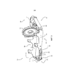
[23] ФИГ.7 представляет собой отдельный вид в перспективе крышки маховика;[23] FIG. 7 is a separate perspective view of a flywheel cover;
[24] ФИГ.8 представляет собой вид в поперечном разрезе крышки маховика ФИГ.7;[24] FIG. 8 is a cross-sectional view of the flywheel cover of FIG. 7;
[25] ФИГ.9 представляет собой блок-схему, показывающую способ сборки с установкой двигателя;[25] FIG. 9 is a flowchart showing an assembly method with engine installation;
[26] ФИГ.10 представляет собой вид снизу рамы под двигатель ФИГ.3; а[26] FIG. 10 is a bottom view of a frame for the engine of FIG. 3; a
[27] ФИГ.11 представляет собой вид в перспективе другого варианта осуществления рамного узла под двигатель.[27] FIG. 11 is a perspective view of another embodiment of a frame assembly for an engine.
[28] Соответствующие ссылочные номера используются для обозначения соответствующих частей на нескольких изображениях.[28] Corresponding reference numbers are used to indicate corresponding parts in several images.
Подробное описание изобретенияDETAILED DESCRIPTION OF THE INVENTION
[29] Варианты осуществления предложенного изобретения, описанные ниже, не предназначены считаться исчерпывающими или ограничивать изобретение точными формами в следующем подробном описании. Вместо этого, варианты осуществления выбраны и описаны таким образом, чтобы квалифицированные специалисты в данной области техники смогли оценить и понять принципы и практические подходы предложенного изобретения.[29] The embodiments of the invention described below are not intended to be exhaustive or to limit the invention to the exact forms in the following detailed description. Instead, embodiments have been selected and described so that those skilled in the art can appreciate and understand the principles and practical approaches of the proposed invention.
[30] Со ссылкой на ФИГ.1 показан вариант осуществления машины 100, такой как погрузчик с бортовым поворотом. Однако, данное изобретение не предназначено для ограничения погрузчиком с бортовым поворотом, но также может содержать любую сельскохозяйственную, строительную или лесотехническую технику. Машина 100 может иметь передний конец 128 и задний конец 130 и может быть снабжена взаимодействующим с землей механизмом для передвижения по земле. На фиг.1 взаимодействующим с землей механизмом может быть пара передних колес 102 и пара задних колес 104. В еще одном аспекте, таком как компактный гусеничный погрузчик, взаимодействующим с землей механизмом может быть ведущая гусеница, расположенная с каждой стороны машины 100. В общепринятом погрузчике с бортовым поворотом оператор может манипулировать органами управления изнутри кабины 112 для управления колесами с правой или с левой стороны машины 100 с различными скоростями для управления посредством этого машиной 100 общепринятым образом.[30] With reference to FIG. 1, an embodiment of a
[31] Машина 100 может быть дополнительно снабжена рабочим орудием или инструментом для выполнения требуемой работы. На фиг.1 машина 100 содержит ковш 106 погрузчика для сбора в него материала и транспортировки указанного материала в требуемое место. Ковш 106 погрузчика может быть шарнирно соединен с передней частью пары стоек 108 стрелы, расположенных с каждой стороны машины 100. Пара гидравлических исполнительных механизмов 114 наклона ковша может продолжаться между ковшом 106 и стойками 108 стрелы для управления наклонной ориентацией ковша 106 относительно стоек 108 стрелы. Каждый гидравлический исполнительный механизм 114 может содержать шток цилиндра, который приводится в движение назад и вперед внутри цилиндра в ответ на изменение гидравлического давления. За счет приведения в действие гидравлических исполнительных механизмов 114 наклона оператор может наклонять ковш 106 для сбора в него материала или выгрузки из него материала.[31]
[32] На фиг.1 ковш 106 погрузчика показан на уровне земли. Для подъема ковша 106 каждая из пары стоек 108 стрелы соединена с верхним звеном 110 в первом шарнире 122 и с нижним звеном 118 во втором шарнире 124. Верхнее звено 110 и нижнее звено 118 также прикреплены к главному шасси 116 машины 100 на противоположных концах, где каждый соединен со стойкой 108 стрелы. Гидравлический исполнительный механизм 120 шарнирно прикреплен на одном конце к главному шасси 116 и соединен со стойкой 108 стрелы на его противоположном конце. Гидравлический исполнительный механизм 120 соединен со стойкой 108 стрелы на третьем шарнире 126.[32] In figure 1, the
[33] Далее со ссылкой на ФИГ.2 показано частичное перспективное изображение 200 машины 100. Машина 100 может образовать внутреннюю полость, которая выполнена с возможностью приема двигателя 202. Двигатель 202 может быть дополнительно соединен с машиной 100 посредством корпуса 204, продолжающегося от заднего конца 130 машины 100 к переднему концу 128 машины 100. Дополнительно, корпус 204 может предусматривать места установки для насосного узла 210 и крышки 212 маховика.[33] Next, with reference to FIG. 2, a
[34] Крышка 212 маховика может иметь по существу кольцевой корпус и быть соединена с двигателем 202. Крышка 212 маховика может образовать по меньшей мере одну лапку 214, которая обеспечивает место для соединения крышки 212 маховика с рабочей машиной 100. Кроме того, крышка 212 маховика также может быть соединена с корпусом 204 вдоль нижней части крышки 212 маховика. В неограничивающем варианте осуществления, показанном на фиг.2, корпус 204 также может быть соединен с машиной 100 посредством соединительного механизма 216 около заднего конца 130. Корпус 204 может частично поддерживаться соединительным механизмом 216 на заднем конце 130 и дополнительно посредством лапок 214 крышки 212 маховика к переднему концу 128. Другими словами, крышка 212 маховика может быть соединена с машиной 100 с помощью лапок 214 и, кроме того, соединяться с частью корпуса 204 для частичной поддержки корпуса 204.[34] The
[35] Далее со ссылкой на ФИГ.3 показано перспективное изображение 300 корпуса 204, виброизолированного от машины 100. Корпус 204 может иметь первый удлиненный элемент 302 вдоль первой стороны 304 и второй удлиненный элемент 306 вдоль второй стороны 308. Первый элемент 302 и второй элемент 306 могут быть соединены друг с другом на заднем конце 130 посредством соединительного механизма 216. Первый элемент 302 может продолжаться от заднего конца 130 вдоль первой стороны 304 корпуса 204 и заканчиваться в креплении 310 насоса на переднем конце 128. Аналогичным образом, второй элемент 306 может продолжаться от заднего конца 130 вдоль второй стороны 308 корпуса 204 и заканчиваться в креплении 310 насоса на переднем конце 128. В одном неограничивающем примере второй элемент 306 может быть по существу зеркальным вариантом осуществления первого элемента 302.[35] Next, with reference to FIG. 3, a
[36] ФИГ.3 также более ясно показывает соединительный механизм 216. Соединительный механизм 216 может соединять первый элемент 302 со вторым элементом 306, дополнительно образуя в то же время соединительное крепление, которое обеспечивает возможность соединения соединительного механизма 216 с машиной 100. В одном варианте осуществления соединительный механизм 216 может быть образован по существу из единственного материала в виде плоской пластины 314, первой стенки 316 и второй стенки 318. Первая стенка 316 и вторая стенка 318 могут быть смещены под углом друг от друга, чтобы соответствовать углу, на который первый элемент 302 и второй элемент 306 изогнуты в направлении соединительного механизма 216. Кроме того, первая стенка 316 и вторая стенка 318 могут быть образованы за счет изгибов относительно плоской пластины 314 таким образом, чтобы позволить им ровно прилегать к первому элементу 302 и второму элементу 306, которые в варианте осуществления, показанном на фиг.3, по существу представляют собой изгибы на 90 градусов. Первая стенка 316 и вторая стенка 318 могут иметь размер, чтобы соответствовать участкам первого и второго элементов 302, 306, которые соединены с соединительным механизмом 216.[36] FIG. 3 also more clearly shows the connecting
[37] Первый и второй элементы 302, 306 могут быть соединены с соединительным механизмом 216 с использованием множества различных способов соединения, и данное изобретение не ограничено каким-либо одним способом соединения. Более конкретно, первый и второй элементы 302, 306 могут иметь сквозные отверстия, которые соответствуют сквозным отверстиям в соединительном механизме 216. Сквозные отверстия могут быть выровнены друг с другом, и для соединения первого и второго элементов 302, 306 с соединительным механизмом 216 может быть использован соединительный механизм, такой как болт и гайка, заклепка или любое другое аналогичное средство соединения. В качестве альтернативы, соединительный механизм 216 может быть приварен или приклеен к первому и второму элементу 302, 306, когда они должным образом выровнены друг с другом.[37] The first and
[38] В еще одном варианте осуществления первый элемент 302, второй элемент 306 и соединительный механизм 216 могут быть образованы из одного непрерывного материала. Вместо соединения составных элементов друг с другом единый материал можно резать, механически обрабатывать, изгибать или формировать иным образом, чтобы создать требуемую форму всего корпуса 204. Специалисту в данной области техники будут понятны различные способы, которые могут быть использованы для создания по существу таких же признаков, которые описаны для корпуса 204, и данное изобретение не ограничено каким-либо одним способом.[38] In yet another embodiment, the
[39] В одном варианте осуществления виброизолятор 324 может быть расположен между соединительным механизмом 216 и машиной 100. Виброизолятор 324 может иметь множество материалов, выполненных с возможностью демпфирования вибрации, передаваемой между двигателем 202 и остальной частью машины 100. Специалист в данной области техники знает множество различных материалов и способов, которые могут использоваться для механических виброизоляторов, и данное изобретение не ограничено каким-либо конкретным типом. Можно использовать материалы, такие как резина, полиуретан, пластмасса и тому подобное, которые включены в данный документ в качестве неограничивающих примеров виброизолятора. Кроме того, в данном документе также рассматриваются механические узлы, такие как демпферы и амортизаторы. В связи с этим, виброизолятор может представлять собой единую деталь материала, или он может содержать дополнительные материалы или составные элементы. Таким образом, в данном раскрытии вместо виброизолятора использован виброизолирующий узел, но термины могут быть использованы взаимозаменяемо. Данное изобретение предусматривает использование любого известного виброизолятора или виброизолирующего узла для виброизоляции друг от друга двух или более конструкций (например, двигателя и шасси машины).[39] In one embodiment, the
[40] Перспективное изображение 300 более ясно показывает, как первый и второй элементы 302, 306 могут быть образованы за счет наличия множества поперечных изгибов 322. Более конкретно, поперечные изгибы 322 могут быть образованы как в первом, так и во втором элементах 302, 306 около места, в котором они соединены с соединительным механизмом 216. Поперечные изгибы 322 могут обеспечивать возможность сужения первого и второго элементов 302, 306 внутрь в направлении друг друга около соединительного механизма 216.[40] The
[41] Дополнительно, первый и второй элементы 302, 306 могут иметь поперечный изгиб 322 в местоположении рядом с крышкой 212 маховика. Поперечный изгиб 322 обеспечивает возможность сужения первого и второго элементов внутрь друг к другу, когда они приближаются к креплению 310 насоса на переднем конце 128. В одном варианте осуществления сужение первого и второго элементов 302, 306 друг в направлении друга, когда они приближаются к креплению 310 насоса, может предусматривать достаточный зазор между первым и вторым элементами 302, 306 и окружающей конструкцией машины 100 для предоставления опций выбора направления для гидравлических шлангов.[41] Additionally, the first and
[42] Однако, данное изобретение не ограничено сужающейся секцией крепления насоса, и доступны другие опции выбора направления для гидравлических шлангов. Например, первый и второй элементы 302, 306 могут не иметь поперечного изгиба 322, но вместо этого могут быть по существу прямыми. В данном варианте осуществления первый и второй элементы 302, 306 могут иметь сквозные отверстия, образованные рядом с насосным узлом 210, чтобы обеспечить возможность направления через них гидравлических линий. Кроме того, в еще одном варианте осуществления первый и второй элементы 302, 306 могут быть по существу прямыми вдоль секции крепления насоса и могут не иметь каких-либо сквозных отверстий через них. В данном варианте осуществления может не быть необходимости направления гидравлических линий под насосным узлом 210.[42] However, the present invention is not limited to a tapering pump mounting section, and other directional options for hydraulic hoses are available. For example, the first and
[43] Крепление 310 насоса может быть расположено между первым элементом 302 и вторым элементом 306 на переднем конце 128 корпуса 204. Крепление 310 насоса также может обеспечивать место поддержки насосного узла 210 или какого-либо другого дополнительного оборудования, которое может быть соединено с двигателем 202. В одном варианте осуществления крепление 310 насоса может быть образовано по существу из одной плоской детали, которая имеет ряд изгибов. Крепление 310 насоса также может иметь укрепляющую пластину 502 (как показано на перспективном изображении снизу 500 ФИГ.5), соединенную вдоль внутренней поверхности крепления 310 насоса. Укрепляющая пластина 502 может обеспечивать повышенную жесткость креплению 310 насоса и посредством этого уменьшать величину вибрации, передаваемой от двигателя 202 в установленный на нем насосный узел 210.[43] A
[44] Поперечные изгибы 322 могут образовать несколько секций, что может быть более ясно понятно со ссылкой на вид 400 сбоку ФИГ.4. Более конкретно, ФИГ.4 иллюстрирует первую секцию 402, вторую секцию 404 и третью секцию 406. Первая секция 402 может переходить во вторую секцию 404 как в первом элементе 302, так и во втором элементе 306 через поперечный изгиб 322. Кроме того, первая секция 402 первого и второго элемента 302, 306 может быть соединена с соединительным механизмом 216. Другими словами, поперечный изгиб 322 между первой секцией 402 и второй секцией 404 может быть достаточным, чтобы обеспечить сужение внутрь первого элемента 302 и второго элемента 306, чтобы соответствовать первой стенке 316 и второй стенке 318 соединительного механизма 216.[44] The transverse bends 322 may form several sections, which may be more clearly understood with reference to a
[45] В одном варианте осуществления первый элемент 302 и второй элемент 306 параллельны друг другу вдоль второй секции 404. В еще одном варианте осуществления крышка 212 маховика может быть установлена на первый и второй элемент 302, 306 во второй секции 404. В данном варианте осуществления первый и второй элемент 302, 306 могут быть по существу параллельны друг другу на протяжении второй секции 404 при соединении с двигателем 202 и крышкой 212 маховика.[45] In one embodiment, the
[46] Несмотря на то, что первый и второй элементы 302, 306 были описаны параллельными друг другу вдоль их соответствующей второй секции 404, данное изобретение не ограничено подобной конфигурацией. Более конкретно, вторая секция 404 каждого элемента может содержать части, которые смещены друг от друга, требуя промежуточных изгибов вдоль второй секции 404. Кроме того, несмотря на то, что один вариант осуществления заявляет установку крышки 212 маховика с соединением или расположением во второй секции 404, крышка 212 маховика также может быть установлена в первой секции 402 или в третьей секции 406.[46] Although the first and
[47] Как раскрыто в данном документе, существуют преимущества изготовления с наличием соединения крышки 212 маховика с корпусом 204 в местах, которые находятся в плоском выравнивании с точками 408 соединения с двигателем, т.е. где двигатель может быть соединен с корпусом 204. Более конкретно, подобное выравнивание может обеспечить, чтобы вторые секции 404 каждого первого и второго элемента 302, 306 были по существу плоскими деталями, не требуя дополнительной производственной стадии изгибания или формирования второй секции 404, так как первый и второй элементы 302, 306 продолжаются от двигателя 202 до крышки 212 маховика. Однако, наличие одного или более изгибов внутри второй секции 404 не отходит от идей данного изобретения. Соответственно, данное изобретение не ограничено параллельными элементами, расположенными вдоль второй секции 404.[47] As disclosed herein, there are manufacturing advantages with having the
[48] Взаимное расположение между по меньшей мере одной точкой 408 соединения двигателя и по меньшей мере одной точкой 410 соединения маховика более ясно проиллюстрировано на изображении 400 сбоку ФИГ.4. По меньшей мере одна точка 410 соединения маховика представляет место, в котором крышка 212 маховика может соединяться с корпусом 204. В одном варианте осуществления крышка 212 маховика может быть соединена со второй секцией 404 в месте вдоль нижней части крышки 212 маховика. За счет соединения крышки 212 маховика в ее нижней части, крышка 212 маховика может быть достаточно прочной для существенного ограничения отклонения насосного узла 210 относительно двигателя 202 при соединении с ним.[48] The relative position between at least one
[49] В одном неисключительном варианте осуществления точка 410 соединения маховика может обеспечивать дополнительную опору вдоль корпуса 204 для существенного ограничения колебания или отклонения иным образом насосного узла 210 относительно крышки 212 маховика. Точка 410 соединения маховика может дополнительно укреплять корпус 204 для уменьшения отклонения между крышкой 212 маховика и насосным узлом 210 вдоль по существу вертикального направления, как показано стрелкой 412 на фиг.4. Однако, отклонение может быть уменьшено также и в других направлениях. Например, корпус 204 также может существенно ограничивать отклонение между насосным узлом 210 и крышкой маховика вдоль направления из стороны в сторону или бокового направления. Дополнительно, корпус 204 может существенно ограничивать отклонение вдоль любой комбинации направлений, и данное изобретение не ограничено каким-либо конкретным направлением.[49] In one non-exclusive embodiment, the
[50] Точка 410 соединения маховика также может ограничивать отклонение первого и второго элементов 302, 306 в направлении 1002 внутрь или в направлении 1004 наружу (см. ФИГ.10). За счет уменьшения возможного отклонения первого и второго элементов 302, 306 в направлении 1002, 1004 внутрь и наружу, может быть увеличена общая прочность и жесткость корпуса 204 и соединенных с ним составных элементов. За счет увеличения жесткости корпуса 204 и за счет соединения насосного узла 210 с корпусом 204 посредством крепления 310 насоса, может быть существенно ограничено отклонение или колебание иным образом насосного узла 210 относительно крышки 212 маховика.[50] The
[51] Далее со ссылкой на ФИГ.6 перспективный вид снизу 600 корпуса 204 иллюстрирует альтернативное крепление 610 насоса. В альтернативном варианте осуществления крепление 610 насоса может быть образовано из единого блока материала вместо детали, содержащей множество изгибов, как описано в предшествующем варианте осуществления крепления 310 насоса. Крепление 610 единого блока насоса может образовать множество установочных отверстий, выполненных с возможностью соединения крепления 610 насоса с первым и вторым элементами 302, 306. В креплении 610 единого блока насоса промежуток между крышкой 212 маховика и креплением 610 насоса может быть больше, чем промежуток от крышки 212 маховика до крепления 310 насоса в предшествующем варианте осуществления. В одном варианте осуществления промежуток между креплением насоса и крышкой 212 маховика может изменяться для размещения различного дополнительного оборудования, которое приводится в действие двигателем 202. В неограничивающем примере механический гидравлический насос может требовать отделения крепления 610 насоса первым промежутком от крышки 212 маховика в то время, как электрический гидравлический узел может требовать отделения крепления 610 насоса другим промежутком от крышки 212 маховика. В других вариантах осуществления промежуток между креплением насоса и крышкой 212 маховика может быть иным, не затрагивая идеи данного изобретения.[51] Next, with reference to FIG. 6, a perspective view from below 600 of the
[52] Далее со ссылкой на ФИГ.7 показано отдельное перспективное изображение 700 крышки 212 маховика. Крышка 212 маховика может иметь по существу кольцевой корпус, образующий отверстие 702, которое может быть выровнено с коленчатым валом двигателя 202. Когда крышка 212 маховика соединена с двигателем 202, маховик двигателя 202 может свободно вращаться внутри полости, создаваемой между крышкой 212 маховика и двигателем 202. Кроме того, вал может располагаться через отверстие 702 для передачи в насосный узел 210 крутящего момента, создаваемого двигателем 202.[52] Next, with reference to FIG. 7, a
[53] В дополнение к установке насосного узла 210 на крепление (310 или 610) насоса, насосный узел 210 также может быть соединен с наружной поверхностью крышки 212 маховика посредством установочной поверхности 704. За счет соединения насосного узла 210 с крышкой 212 маховика насосный узел 210 может располагаться в правильном выравнивании с коленчатым валом двигателя 202, обеспечивая в то же время также точку конструктивного соединения между насосным узлом 210 и двигателем 202. Соответственно, жесткость крышки 212 маховика может уменьшать вибрацию двигателя 202 и насосного узла 210.[53] In addition to mounting the
[54] Еще одним аспектом предложенного изобретения является изменяющаяся или варьирующая толщина крышки 212 маховика для создания более жесткого соединения между насосным узлом 210 и двигателем 202. Данный вариант осуществления может быть лучше понятен при рассмотрении изображения 800 крышки 212 маховика в поперечном разрезе, показанном на фиг.8. Крышка 212 маховика может иметь первую толщину 802, которая находится в первом промежутке рядом с отверстием 702, и вторую толщину 804, которая находится во втором промежутке от отверстия 702. Второй промежуток может быть больше, чем первый промежуток, а толщина крышки 212 маховика может сужаться с уменьшением по мере перехода от первой толщины 802 ко второй толщине 804. Первая и вторая толщина 802, 804 может иметь достаточный размер, чтобы обеспечивать свободное вращение маховика без контакта с крышкой 212 маховика. Кроме того, в одном неисключительном варианте осуществления вторая толщина 804 может иметь размер, обеспечивающий возможность расположения соединительных механизмов маховика внутри полости без контакта с крышкой 212 маховика.[54] Another aspect of the proposed invention is the varying or varying thickness of the
[55] Несмотря на то, что иллюстрация ФИГ.8 и описание выше соответственно показывают и описывают поперечное сечение крышки 212 маховика, имеющей толщину, которая сужается с уменьшением от первой толщины 802 ко второй толщине 804, данное изобретение не ограничено подобной конфигурацией. Другие варианты осуществления могут содержать изменения толщины, например, в виде ступенчатого изменения, гиперболического изменения и любого другого известного изменения. Если изменение толщины достигалось в ступенчатой конфигурации, первая толщина 802 может быть постоянной до тех пор, пока она не достигнет места, которое требует изменения толщины, т.е. для размещения соединительных механизмов на крышке 212 маховика. В этом месте толщина крышки 212 маховика может изменяться ступенчатым образом от первой толщины 802 ко второй толщине 804. В дополнение, свойства материала крышки 212 маховика также могут влиять на жесткость системы. Например, чугун с шаровидным графитом может обеспечивать более жесткую крышку 212 маховика, чем серый литейный чугун. Соответственно, в данном документе также предусматривается изготовление крышки 212 маховика из материалов с различными свойствами материала. Специалисту в данной области техники следует понимать, что крышка 212 маховика может быть сконструирована из алюминия, стали, нержавеющей стали, титана или любого другого материала, широко используемого в данной области, для получения преимущества некоторых свойств материала, например, для увеличения жесткости и прочности крышки 212 маховика.[55] Although the illustration of FIG. 8 and the description above respectively show and describe a cross section of a
[56] Со ссылкой на ФИГ.10 на изображении 1000 снизу рамы или корпуса 204 под двигатель показаны две лапки 214. Несмотря на то, что один вариант осуществления может иметь две лапки 214, данное изобретение предусматривает любое количество лапок 214 и не ограничено какой-либо конкретной конфигурацией. Лапки 214 могут выступать из кольцевого корпуса крышки 212 маховика и быть радиально отделенными друг от друга таким образом, чтобы обеспечить возможность соединения лапок 214 с машиной 100 посредством первого виброизолирующего узла 1010 и второго виброизолирующего узла 1012.[56] With reference to FIG. 10, two
[57] В одном варианте осуществления рама или корпус 204 под двигатель может быть соединен с машиной 100 только посредством виброизолирующего узла в соединительном механизме 216. Корпус 204 может быть дополнительно соединен с крышкой 212 маховика и с двигателем 202. Крышка 212 маховика также может быть соединена с машиной 100 посредством виброизолирующих узлов в лапках 214. В данном варианте осуществления корпус 204 соединен с машиной 100 посредством соединительного механизма 216 и, кроме того, соединен как с двигателем 202, так и с крышкой 212 маховика. В данной конфигурации корпус 204, двигатель 202 и крышка 212 маховика соединены друг с другом с предоставлением по существу жесткого узла, который соединен с машиной 100 посредством лапок 214 крышки маховика и соединительного механизма 216.[57] In one embodiment, the engine frame or
[58] На фиг.11 проиллюстрирован еще один вариант осуществления рамы или корпуса 1100 под двигатель. В данном варианте осуществления по существу плоская пластина 1102 может быть соединена на заднем конце рамы или корпуса 1100 и с нижней частью первого элемента 302 и второго элемента 306. Как показано, рама или корпус 1100 может содержать пару опор 1104, соединенных в задней части первого и второго элементов 302, 306, а также вдоль верхней поверхности плоской пластины 1102. В связи с этим, пара опор 1104 и первый и второй элементы 302, 306 ориентированы по существу перпендикулярно пластине 1102. В данном варианте осуществления пара опор 1104 может быть соединена с первым и вторым элементами 302, 306 посредством множества способов соединения, включая, но без ограничения способы, описанные ранее для соединительного механизма 216.[58] Figure 11 illustrates another embodiment of a frame or
[59] Вариант осуществления выше может предусматривать по существу жесткий механический узел для существенного уменьшения вероятности подвергания составных элементов экстремальным силам вследствие вибрациям, создаваемым двигателем или гидравлическим насосом. Например, многие двигатели создают синусоидальный вибрационный вход в шасси и составные элементы, соединенные с ним. Синусоидальная вибрация может генерироваться вращающимися составными элементами двигателя, которые уравновешены не должным образом при вращении в нем. Дополнительно, любые составные элементы, приводимые в действие двигателем, могут обеспечивать дополнительный вибрационный вход в составные элементы, соединенные с шасси и двигателем. Конкретный профиль вибрации может изменяться в зависимости от скорости вращения двигателя и свойств материал шасси и других составных элементов, соединенных с двигателем. В некоторых обстоятельствах резонансная частота может быть реализована составными элементами, соединенными с двигателем, являясь причиной того, что данные составные элементы испытывают повышенное напряжение и деформацию в точках их соединения с другими составными элементами.[59] The embodiment above may provide a substantially rigid mechanical assembly to substantially reduce the likelihood of the components being exposed to extreme forces due to vibrations generated by the engine or hydraulic pump. For example, many engines create a sinusoidal vibrational input to the chassis and the components connected to it. Sinusoidal vibration can be generated by the rotating components of the engine, which are not properly balanced when rotated in it. Additionally, any constituent elements driven by the engine may provide additional vibrational input into the constituent elements connected to the chassis and the engine. The specific vibration profile may vary depending on the speed of the engine and the properties of the chassis material and other components connected to the engine. In some circumstances, the resonant frequency can be realized by constituent elements connected to the motor, causing these constituent elements to experience increased stress and deformation at the points of their connection with other constituent elements.
[60] Свойства материала, места соединения и размеры третьей секции 406 корпуса 204 могут влиять на тяжесть вибраций, испытываемых насосным узлом 210. В одном неисключительном примере недостаточная жесткость между насосным узлом 210 и двигателем 202 может приводить к профилю вибрации, который является причиной большего, чем требуется относительного передвижения между двигателем 202, насосным узлом 210 или любым из составных элементов, соединяющих их друг с другом. Более конкретно, если третья секция 406 испытывает упругую деформацию вследствие вибрационного входа двигателя 202 и/или насосного узла 210, насосный узел 210 может отклоняться наподобие трамплина относительно двигателя 202.[60] The material properties, joints, and dimensions of the
[61] В варианте осуществления, показанном на фиг.5, насосный узел 210 может быть соединен с двигателем 202 через крепление 310 насоса с первым промежутком от крышки 504 маховика. В данном неограничивающем варианте осуществления первый промежуток от крышки 504 маховика в дополнение к соединению корпуса 204 с крышкой 212 маховика в точке 410 соединения маховика может обеспечивать достаточную жесткость между насосным узлом 210 и двигателем 202 для ограничения какого-либо существенного отклонения в корпусе 204 вдоль третьей секции 406. За счет обеспечения достаточной жесткости между корпусом 204, насосным узлом 210 и двигателем 2020, может быть существенно уменьшено отклонение насосного узла 210, вызываемое профилями вибрации, генерируемой двигателем 202 и/или насосным узлом 210.[61] In the embodiment shown in FIG. 5, the
[62] Показан другой вариант осуществления, когда крепление 610 насоса находится со вторым промежутком от крышки 602 маховика на фиг.6. В данном варианте осуществления второй промежуток от крышки 602 маховика может быть больше, чем первый промежуток от крышки 504 маховика. За счет увеличения промежутка между креплением 610 насоса и крышкой 212 маховика, может быть увеличен возможный изгибающий момент в насосном узле 210. Другими словами, насосный узел 210 может подвергаться большему изгибающему моменту, чем дальше насосный узел 210 и крепление 610 насоса продолжаются от двигателя 202. В одном неограничивающем примере насосный узел 210 может иметь тенденцию к большему отклонению относительно двигателя 202, чем дальше крепление 610 насоса находится от крышки 212 маховика.[62] Another embodiment is shown when the
[63] В варианте осуществления ФИГ.6 может быть необходимо увеличивать жесткость третьей секции 406 за счет изменения свойств материала корпуса 204. В одном неограничивающем примере может требоваться увеличение толщины корпуса для достаточной опоры насосного узла 210 во втором промежутке от крышки 602 маховика. Кроме того, в данном варианте осуществления также может использоваться крышка 212 маховика с изменяемой толщиной, как показано на фиг.8, для соответствия повышенному потенциалу отклонения между двигателем 202 и насосным узлом 210.[63] In the embodiment of FIG. 6, it may be necessary to increase the rigidity of the
[64] Соответственно, корпус 204 обеспечивает существенную конструктивную жесткость между насосным узлом 210 и двигателем 202 для ограничения или уменьшения отклонения между насосным узлом 210 и двигателем 202. Кроме того, данное изобретение заявляет предоставление множества мест крепления насоса относительно крышки маховика, и идеи, предоставленные в данном документе, не должны ограничиваться каким-либо конкретным местом крепления насоса. Данные идеи также равно применимы к любому другому составному элементу, который может быть установлен на двигатель или шасси. Например, вместо установки насосного узла на двигатель, на нем может быть установлена трансмиссия. Трансмиссия может быть установлена на крепление трансмиссии вдоль корпуса 204 с использованием идей данного изобретения. Соответственно, применение данного изобретения не должно ограничиваться только насосным узлом, но должно рассматриваться применение к любому составному элементу, который может быть соединен и/или приводиться в действие двигателем.[64] Accordingly, the
[65] В одном варианте осуществления корпус может предоставлять достаточную конструктивную основу для существенного ограничения резонирования насосного узла в результате вибраций, создаваемых работающим двигателем. Кроме того, в одном варианте осуществления утолщенный участок крышки маховика может существенно ограничивать отклонение между насосным узлом и крышкой маховика. В еще одном варианте осуществления может отсутствовать необходимость утолщения маховика с целью отклонения.[65] In one embodiment, the housing may provide a sufficient structural basis for substantially limiting the resonance of the pump assembly as a result of vibrations generated by a running engine. In addition, in one embodiment, the thickened portion of the flywheel cover may substantially limit the deviation between the pump assembly and the flywheel cover. In yet another embodiment, there may be no need to thicken the flywheel to deflect.
[66] Далее со ссылкой на ФИГ.9 на блок-схеме 900 показан способ сборки с установкой двигателя. В одном аспекте предложенного изобретения, как показано в блоке 902, могут быть предоставлены машина 100 и двигатель 202. В блоке 904 крышка 212 маховика может быть соединена с двигателем 202. Далее в блоке 906 первый элемент 302 может быть соединен с двигателем 202. В блоке 908 первый элемент 302 может быть соединен с крышкой 212 маховика. Дальше в блоке 910 первый элемент 302 может быть соединен с соединительным механизмом 216 на одном конце и с креплением 310 насоса на другом конце.[66] Next, with reference to FIG. 9, a
[67] Аналогичным образом, в блоке 912 второй элемент 306 может быть соединен с двигателем 202. В блоке 914 второй элемент 306 также может быть соединен с крышкой 212 маховика. В блоке 916 второй элемент 306 может быть дополнительно соединен с соединительным механизмом 216 на заднем конце 130 и с креплением 310 насоса к переднему концу 128.[67] Similarly, in
[68] В блоке 918 насосный узел 210 может быть соединен с креплением 310 насоса и крышкой 212 маховика вдоль установочной поверхности 704. Затем в блоке 920 первый и второй виброизолирующие узлы 1010, 1012 (ФИГ.10) могут быть помещены на лапки 214 крышки 212 маховика, и при этом третий виброизолирующий узел 324 может быть помещен на соединительный механизм 216. В блоке 922 двигатель 202, крышка 212 маховика и корпус 204 могут быть помещены в машину 100 так, чтобы лапки 214 и соединительный механизм 216 были выровнены, обеспечивая возможность соединения корпуса 204 и крышки 212 маховика с машиной 100 через соответствующие виброизолирующие узлы 1010, 1012, 324.[68] In
[69] Несмотря на то, что данный способ сборки был описан приведенным выше образом, специалисту в данной области техники следует понимать, что стадии сборки, описанные в данном документе, могут быть выполнены с множеством различных очередностей. Например, корпус 204 может быть соединен с машиной 100 перед соединением с двигателем 202 или крышкой 212 маховика. Соответственно, данное изобретение не ограничено каким-либо конкретным порядком сборки.[69] Although this assembly method has been described in the manner described above, one skilled in the art should understand that the assembly steps described herein can be performed in many different ways. For example,
[70] Несмотря на то, что выше в данном документе были описанные варианты осуществления, включающие принципы предложенного изобретения, предложенное изобретение не ограничено описанными вариантами осуществления. Вместо этого, данная заявка охватывает любые варианты, способы применения или адаптации изобретения с использованием его общих принципов. Кроме того, данная заявка охватывает такие отклонения от предложенного изобретения, которые попадают в пределы известной или общепринятой практики в области, к которой относится данное изобретение, и которые попадают в рамки приложенной формулы изобретения.[70] Although the embodiments described above incorporating the principles of the proposed invention have been described above, the proposed invention is not limited to the described embodiments. Instead, this application covers any variations, methods of application or adaptation of the invention using its general principles. In addition, this application covers such deviations from the proposed invention that fall within the known or generally accepted practice in the field to which this invention relates, and which fall within the scope of the attached claims.
Claims (45)
Applications Claiming Priority (2)
| Application Number | Priority Date | Filing Date | Title |
|---|---|---|---|
| US14/746,959 | 2015-06-23 | ||
| US14/746,959 US9586466B2 (en) | 2015-06-23 | 2015-06-23 | Engine cradle assembly |
Publications (3)
| Publication Number | Publication Date |
|---|---|
| RU2016111633A RU2016111633A (en) | 2017-10-04 |
| RU2016111633A3 RU2016111633A3 (en) | 2019-09-03 |
| RU2714662C2 true RU2714662C2 (en) | 2020-02-18 |
Family
ID=57601808
Family Applications (1)
| Application Number | Title | Priority Date | Filing Date |
|---|---|---|---|
| RU2016111633A RU2714662C2 (en) | 2015-06-23 | 2016-03-29 | Working machine frame assembly (embodiments) and working machine |
Country Status (3)
| Country | Link |
|---|---|
| US (1) | US9586466B2 (en) |
| BR (1) | BR202016003330U8 (en) |
| RU (1) | RU2714662C2 (en) |
Cited By (1)
| Publication number | Priority date | Publication date | Assignee | Title |
|---|---|---|---|---|
| RU2797522C1 (en) * | 2023-01-18 | 2023-06-06 | АКЦИОНЕРНОЕ ОБЩЕСТВО "АКЦИОНЕРНАЯ КОМПАНИЯ "ТУЛАМАШЗАВОД" (АО "АК "Туламашзавод") | Frame of a diesel generator unit, set of support and anti-resonance vibration isolators for the frame of a diesel generator unit, diesel generator unit in a frame and a monoblock diesel generator unit in a frame |
Families Citing this family (1)
| Publication number | Priority date | Publication date | Assignee | Title |
|---|---|---|---|---|
| CN107618589B (en) * | 2017-09-07 | 2019-06-28 | 安徽江淮汽车集团股份有限公司 | A kind of fixed structure of symmetrical bending part |
Citations (4)
| Publication number | Priority date | Publication date | Assignee | Title |
|---|---|---|---|---|
| US3895728A (en) * | 1973-02-05 | 1975-07-22 | Clark Equipment Co | Tractor vehicle having material handling subframe |
| US4055262A (en) * | 1976-02-02 | 1977-10-25 | Clark Equipment Company | Loader main frame for skid steer loader |
| RU128592U1 (en) * | 2012-12-12 | 2013-05-27 | Общество с ограниченной ответственностью "Объединенный инженерный центр" (ООО "ОИЦ") | SUB-FRAME OF INDEPENDENT SUSPENSION OF THE FRONT WHEELS OF THE VEHICLE |
| RU129899U1 (en) * | 2013-03-12 | 2013-07-10 | Закрытое акционерное общество "Агротехмаш" | BEARING PART OF A WHEEL VEHICLE |
Family Cites Families (11)
| Publication number | Priority date | Publication date | Assignee | Title |
|---|---|---|---|---|
| US4449606A (en) * | 1980-07-18 | 1984-05-22 | Veda, Inc. | Vehicle frame assembly |
| US4815550A (en) * | 1987-08-21 | 1989-03-28 | Clark Equipment Company | Engine cooling system for skid steer loaders |
| US6108907A (en) * | 1998-06-05 | 2000-08-29 | Caterpillar S.A.R.L. | Method of assembling a work machine |
| US6167980B1 (en) | 1998-06-05 | 2001-01-02 | Caterpillar S.A.R.L. | Engine mounting and stabilizing arrangement |
| US6138786A (en) | 1998-06-05 | 2000-10-31 | Caterpillar S.A.R.L. | Upper frame assembly |
| JP4458531B2 (en) * | 2004-10-01 | 2010-04-28 | ヤンマー株式会社 | Work vehicle |
| US20080078917A1 (en) | 2006-10-03 | 2008-04-03 | Roehrl Jonathan J | Engine mount |
| US7866700B2 (en) * | 2008-02-11 | 2011-01-11 | Caterpillar Inc | Machine frame |
| US8545163B2 (en) * | 2008-06-26 | 2013-10-01 | Kubota Corporation | Loader work machine |
| JP5247848B2 (en) * | 2011-03-31 | 2013-07-24 | 株式会社小松製作所 | Construction machinery |
| WO2014125622A1 (en) * | 2013-02-15 | 2014-08-21 | 株式会社小松製作所 | Hydraulic shovel |
-
2015
- 2015-06-23 US US14/746,959 patent/US9586466B2/en not_active Expired - Fee Related
-
2016
- 2016-02-17 BR BR202016003330U patent/BR202016003330U8/en not_active IP Right Cessation
- 2016-03-29 RU RU2016111633A patent/RU2714662C2/en active
Patent Citations (4)
| Publication number | Priority date | Publication date | Assignee | Title |
|---|---|---|---|---|
| US3895728A (en) * | 1973-02-05 | 1975-07-22 | Clark Equipment Co | Tractor vehicle having material handling subframe |
| US4055262A (en) * | 1976-02-02 | 1977-10-25 | Clark Equipment Company | Loader main frame for skid steer loader |
| RU128592U1 (en) * | 2012-12-12 | 2013-05-27 | Общество с ограниченной ответственностью "Объединенный инженерный центр" (ООО "ОИЦ") | SUB-FRAME OF INDEPENDENT SUSPENSION OF THE FRONT WHEELS OF THE VEHICLE |
| RU129899U1 (en) * | 2013-03-12 | 2013-07-10 | Закрытое акционерное общество "Агротехмаш" | BEARING PART OF A WHEEL VEHICLE |
Cited By (1)
| Publication number | Priority date | Publication date | Assignee | Title |
|---|---|---|---|---|
| RU2797522C1 (en) * | 2023-01-18 | 2023-06-06 | АКЦИОНЕРНОЕ ОБЩЕСТВО "АКЦИОНЕРНАЯ КОМПАНИЯ "ТУЛАМАШЗАВОД" (АО "АК "Туламашзавод") | Frame of a diesel generator unit, set of support and anti-resonance vibration isolators for the frame of a diesel generator unit, diesel generator unit in a frame and a monoblock diesel generator unit in a frame |
Also Published As
| Publication number | Publication date |
|---|---|
| RU2016111633A (en) | 2017-10-04 |
| US20160375751A1 (en) | 2016-12-29 |
| US9586466B2 (en) | 2017-03-07 |
| BR202016003330U2 (en) | 2017-01-03 |
| RU2016111633A3 (en) | 2019-09-03 |
| BR202016003330U8 (en) | 2018-02-27 |
Similar Documents
| Publication | Publication Date | Title |
|---|---|---|
| KR100327730B1 (en) | Construction machinery with cab | |
| CN103895488B (en) | Power unit for multi-purpose vehicle | |
| RU2418691C1 (en) | Automotive suspension | |
| EP3332999B1 (en) | Engine device support structure and engine device installation method | |
| CN103895485B (en) | Mounting structure for the power unit of multi-purpose vehicle | |
| JP5541709B2 (en) | Construction machinery | |
| EP1908618A1 (en) | Engine mount | |
| RU2714662C2 (en) | Working machine frame assembly (embodiments) and working machine | |
| RU2758728C2 (en) | Monoblock device for supporting power plant, containing intermediate support | |
| EP3498512A1 (en) | Elastic device of a motor-vehicle engine suspension | |
| JP4188642B2 (en) | Construction machinery | |
| CN101341299A (en) | Vibration plate with stabilizing device | |
| JP4256230B2 (en) | Construction machinery | |
| KR101673613B1 (en) | Bracket for supporting drive shaft of construction machinery | |
| CN108995523B (en) | Equipment support structure for motor vehicle | |
| JP2016210343A (en) | Vibration isolation structure of construction machine | |
| JP2005083019A (en) | Construction machinery | |
| CN211259466U (en) | Vibration damping system and working machine comprising same | |
| JP6149875B2 (en) | Engine support structure for construction machine and method for assembling the same | |
| KR20220002325U (en) | Multi-axis and transverse vibration isolation MR mount assembly for vibration reduction in heavy equipment cabin | |
| JPH074356Y2 (en) | Anti-vibration device for vehicle engine | |
| US20130051965A1 (en) | Articulated work machine | |
| CN109843621B (en) | Fastening system for fastening a drive unit to a vehicle body structure | |
| KR200454940Y1 (en) | Engine Mounting Structure for Farm Vehicles | |
| JPH11140909A (en) | Construction machine with cab |