RU2708222C2 - Heart valve leaflet capture device - Google Patents
Heart valve leaflet capture device Download PDFInfo
- Publication number
- RU2708222C2 RU2708222C2 RU2017127898A RU2017127898A RU2708222C2 RU 2708222 C2 RU2708222 C2 RU 2708222C2 RU 2017127898 A RU2017127898 A RU 2017127898A RU 2017127898 A RU2017127898 A RU 2017127898A RU 2708222 C2 RU2708222 C2 RU 2708222C2
- Authority
- RU
- Russia
- Prior art keywords
- sash
- valve
- elements
- gripping
- atrial
- Prior art date
Links
- 210000003709 heart valve Anatomy 0.000 title claims abstract description 29
- 230000001746 atrial effect Effects 0.000 claims abstract description 43
- 239000000523 sample Substances 0.000 claims abstract description 33
- 230000007246 mechanism Effects 0.000 claims abstract description 17
- 230000009471 action Effects 0.000 claims abstract description 9
- 230000000747 cardiac effect Effects 0.000 claims abstract description 6
- 210000002837 heart atrium Anatomy 0.000 claims abstract 2
- 238000000034 method Methods 0.000 claims description 33
- 238000005452 bending Methods 0.000 claims description 15
- 230000000295 complement effect Effects 0.000 claims description 7
- 210000004115 mitral valve Anatomy 0.000 abstract description 48
- 230000001154 acute effect Effects 0.000 abstract description 5
- 230000000694 effects Effects 0.000 abstract description 2
- 239000003814 drug Substances 0.000 abstract 1
- 239000000126 substance Substances 0.000 abstract 1
- 229920003266 Leaf® Polymers 0.000 description 32
- 210000005240 left ventricle Anatomy 0.000 description 16
- 210000005246 left atrium Anatomy 0.000 description 11
- 230000015572 biosynthetic process Effects 0.000 description 9
- 210000005069 ears Anatomy 0.000 description 9
- 238000005755 formation reaction Methods 0.000 description 9
- 230000008439 repair process Effects 0.000 description 9
- 230000008859 change Effects 0.000 description 7
- 238000011084 recovery Methods 0.000 description 7
- 239000008280 blood Substances 0.000 description 6
- 210000004369 blood Anatomy 0.000 description 6
- 210000003484 anatomy Anatomy 0.000 description 5
- 230000000903 blocking effect Effects 0.000 description 5
- 238000012544 monitoring process Methods 0.000 description 5
- 210000001765 aortic valve Anatomy 0.000 description 4
- 238000012790 confirmation Methods 0.000 description 4
- 230000006870 function Effects 0.000 description 4
- 210000002414 leg Anatomy 0.000 description 4
- 239000000463 material Substances 0.000 description 4
- 238000013459 approach Methods 0.000 description 3
- 230000008602 contraction Effects 0.000 description 3
- 238000012795 verification Methods 0.000 description 3
- 206010067171 Regurgitation Diseases 0.000 description 2
- 238000006073 displacement reaction Methods 0.000 description 2
- 210000003191 femoral vein Anatomy 0.000 description 2
- 238000003780 insertion Methods 0.000 description 2
- 230000037431 insertion Effects 0.000 description 2
- 208000005907 mitral valve insufficiency Diseases 0.000 description 2
- 238000010561 standard procedure Methods 0.000 description 2
- 238000001356 surgical procedure Methods 0.000 description 2
- 238000010146 3D printing Methods 0.000 description 1
- 206010007559 Cardiac failure congestive Diseases 0.000 description 1
- 102000008186 Collagen Human genes 0.000 description 1
- 108010035532 Collagen Proteins 0.000 description 1
- 206010019280 Heart failures Diseases 0.000 description 1
- 206010027727 Mitral valve incompetence Diseases 0.000 description 1
- 208000012287 Prolapse Diseases 0.000 description 1
- 241000251539 Vertebrata <Metazoa> Species 0.000 description 1
- 230000003213 activating effect Effects 0.000 description 1
- 229910045601 alloy Inorganic materials 0.000 description 1
- 239000000956 alloy Substances 0.000 description 1
- 210000003157 atrial septum Anatomy 0.000 description 1
- 230000009286 beneficial effect Effects 0.000 description 1
- 210000004763 bicuspid Anatomy 0.000 description 1
- 230000017531 blood circulation Effects 0.000 description 1
- 238000009530 blood pressure measurement Methods 0.000 description 1
- 238000005266 casting Methods 0.000 description 1
- 229920001436 collagen Polymers 0.000 description 1
- 238000004891 communication Methods 0.000 description 1
- 238000002592 echocardiography Methods 0.000 description 1
- 230000007717 exclusion Effects 0.000 description 1
- 230000002349 favourable effect Effects 0.000 description 1
- 210000001105 femoral artery Anatomy 0.000 description 1
- 238000002594 fluoroscopy Methods 0.000 description 1
- 238000003384 imaging method Methods 0.000 description 1
- 230000001771 impaired effect Effects 0.000 description 1
- 239000007943 implant Substances 0.000 description 1
- 210000004072 lung Anatomy 0.000 description 1
- 238000003754 machining Methods 0.000 description 1
- 229910001000 nickel titanium Inorganic materials 0.000 description 1
- HLXZNVUGXRDIFK-UHFFFAOYSA-N nickel titanium Chemical compound [Ti].[Ti].[Ti].[Ti].[Ti].[Ti].[Ti].[Ti].[Ti].[Ti].[Ti].[Ni].[Ni].[Ni].[Ni].[Ni].[Ni].[Ni].[Ni].[Ni].[Ni].[Ni].[Ni].[Ni].[Ni] HLXZNVUGXRDIFK-UHFFFAOYSA-N 0.000 description 1
- 230000003287 optical effect Effects 0.000 description 1
- 210000003540 papillary muscle Anatomy 0.000 description 1
- 230000001575 pathological effect Effects 0.000 description 1
- 230000037361 pathway Effects 0.000 description 1
- 238000002271 resection Methods 0.000 description 1
- 229910001285 shape-memory alloy Inorganic materials 0.000 description 1
- 210000002435 tendon Anatomy 0.000 description 1
- 210000000779 thoracic wall Anatomy 0.000 description 1
- 210000000689 upper leg Anatomy 0.000 description 1
- 230000002792 vascular Effects 0.000 description 1
- 238000012800 visualization Methods 0.000 description 1
Images


Classifications
-
- A—HUMAN NECESSITIES
- A61—MEDICAL OR VETERINARY SCIENCE; HYGIENE
- A61F—FILTERS IMPLANTABLE INTO BLOOD VESSELS; PROSTHESES; DEVICES PROVIDING PATENCY TO, OR PREVENTING COLLAPSING OF, TUBULAR STRUCTURES OF THE BODY, e.g. STENTS; ORTHOPAEDIC, NURSING OR CONTRACEPTIVE DEVICES; FOMENTATION; TREATMENT OR PROTECTION OF EYES OR EARS; BANDAGES, DRESSINGS OR ABSORBENT PADS; FIRST-AID KITS
- A61F2/00—Filters implantable into blood vessels; Prostheses, i.e. artificial substitutes or replacements for parts of the body; Appliances for connecting them with the body; Devices providing patency to, or preventing collapsing of, tubular structures of the body, e.g. stents
- A61F2/02—Prostheses implantable into the body
- A61F2/24—Heart valves ; Vascular valves, e.g. venous valves; Heart implants, e.g. passive devices for improving the function of the native valve or the heart muscle; Transmyocardial revascularisation [TMR] devices; Valves implantable in the body
- A61F2/2442—Annuloplasty rings or inserts for correcting the valve shape; Implants for improving the function of a native heart valve
- A61F2/2463—Implants forming part of the valve leaflets
-
- A—HUMAN NECESSITIES
- A61—MEDICAL OR VETERINARY SCIENCE; HYGIENE
- A61B—DIAGNOSIS; SURGERY; IDENTIFICATION
- A61B17/00—Surgical instruments, devices or methods
- A61B17/00234—Surgical instruments, devices or methods for minimally invasive surgery
-
- A—HUMAN NECESSITIES
- A61—MEDICAL OR VETERINARY SCIENCE; HYGIENE
- A61B—DIAGNOSIS; SURGERY; IDENTIFICATION
- A61B17/00—Surgical instruments, devices or methods
- A61B17/064—Surgical staples, i.e. penetrating the tissue
- A61B17/0643—Surgical staples, i.e. penetrating the tissue with separate closing member, e.g. for interlocking with staple
-
- A—HUMAN NECESSITIES
- A61—MEDICAL OR VETERINARY SCIENCE; HYGIENE
- A61B—DIAGNOSIS; SURGERY; IDENTIFICATION
- A61B17/00—Surgical instruments, devices or methods
- A61B17/068—Surgical staplers, e.g. containing multiple staples or clamps
- A61B17/0682—Surgical staplers, e.g. containing multiple staples or clamps for applying U-shaped staples or clamps, e.g. without a forming anvil
-
- A—HUMAN NECESSITIES
- A61—MEDICAL OR VETERINARY SCIENCE; HYGIENE
- A61B—DIAGNOSIS; SURGERY; IDENTIFICATION
- A61B17/00—Surgical instruments, devices or methods
- A61B17/12—Surgical instruments, devices or methods for ligaturing or otherwise compressing tubular parts of the body, e.g. blood vessels or umbilical cord
- A61B17/122—Clamps or clips, e.g. for the umbilical cord
-
- A—HUMAN NECESSITIES
- A61—MEDICAL OR VETERINARY SCIENCE; HYGIENE
- A61B—DIAGNOSIS; SURGERY; IDENTIFICATION
- A61B17/00—Surgical instruments, devices or methods
- A61B17/12—Surgical instruments, devices or methods for ligaturing or otherwise compressing tubular parts of the body, e.g. blood vessels or umbilical cord
- A61B17/128—Surgical instruments, devices or methods for ligaturing or otherwise compressing tubular parts of the body, e.g. blood vessels or umbilical cord for applying or removing clamps or clips
- A61B17/1285—Surgical instruments, devices or methods for ligaturing or otherwise compressing tubular parts of the body, e.g. blood vessels or umbilical cord for applying or removing clamps or clips for minimally invasive surgery
-
- A—HUMAN NECESSITIES
- A61—MEDICAL OR VETERINARY SCIENCE; HYGIENE
- A61B—DIAGNOSIS; SURGERY; IDENTIFICATION
- A61B17/00—Surgical instruments, devices or methods
- A61B17/28—Surgical forceps
- A61B17/29—Forceps for use in minimally invasive surgery
-
- A—HUMAN NECESSITIES
- A61—MEDICAL OR VETERINARY SCIENCE; HYGIENE
- A61F—FILTERS IMPLANTABLE INTO BLOOD VESSELS; PROSTHESES; DEVICES PROVIDING PATENCY TO, OR PREVENTING COLLAPSING OF, TUBULAR STRUCTURES OF THE BODY, e.g. STENTS; ORTHOPAEDIC, NURSING OR CONTRACEPTIVE DEVICES; FOMENTATION; TREATMENT OR PROTECTION OF EYES OR EARS; BANDAGES, DRESSINGS OR ABSORBENT PADS; FIRST-AID KITS
- A61F2/00—Filters implantable into blood vessels; Prostheses, i.e. artificial substitutes or replacements for parts of the body; Appliances for connecting them with the body; Devices providing patency to, or preventing collapsing of, tubular structures of the body, e.g. stents
- A61F2/02—Prostheses implantable into the body
- A61F2/24—Heart valves ; Vascular valves, e.g. venous valves; Heart implants, e.g. passive devices for improving the function of the native valve or the heart muscle; Transmyocardial revascularisation [TMR] devices; Valves implantable in the body
- A61F2/2442—Annuloplasty rings or inserts for correcting the valve shape; Implants for improving the function of a native heart valve
- A61F2/2466—Delivery devices therefor
-
- A—HUMAN NECESSITIES
- A61—MEDICAL OR VETERINARY SCIENCE; HYGIENE
- A61B—DIAGNOSIS; SURGERY; IDENTIFICATION
- A61B17/00—Surgical instruments, devices or methods
- A61B2017/00017—Electrical control of surgical instruments
- A61B2017/00022—Sensing or detecting at the treatment site
-
- A—HUMAN NECESSITIES
- A61—MEDICAL OR VETERINARY SCIENCE; HYGIENE
- A61B—DIAGNOSIS; SURGERY; IDENTIFICATION
- A61B17/00—Surgical instruments, devices or methods
- A61B17/00234—Surgical instruments, devices or methods for minimally invasive surgery
- A61B2017/00238—Type of minimally invasive operation
- A61B2017/00243—Type of minimally invasive operation cardiac
-
- A—HUMAN NECESSITIES
- A61—MEDICAL OR VETERINARY SCIENCE; HYGIENE
- A61B—DIAGNOSIS; SURGERY; IDENTIFICATION
- A61B17/00—Surgical instruments, devices or methods
- A61B17/00234—Surgical instruments, devices or methods for minimally invasive surgery
- A61B2017/00292—Surgical instruments, devices or methods for minimally invasive surgery mounted on or guided by flexible, e.g. catheter-like, means
- A61B2017/003—Steerable
- A61B2017/00305—Constructional details of the flexible means
- A61B2017/00309—Cut-outs or slits
-
- A—HUMAN NECESSITIES
- A61—MEDICAL OR VETERINARY SCIENCE; HYGIENE
- A61B—DIAGNOSIS; SURGERY; IDENTIFICATION
- A61B17/00—Surgical instruments, devices or methods
- A61B17/00234—Surgical instruments, devices or methods for minimally invasive surgery
- A61B2017/00292—Surgical instruments, devices or methods for minimally invasive surgery mounted on or guided by flexible, e.g. catheter-like, means
- A61B2017/00336—Surgical instruments, devices or methods for minimally invasive surgery mounted on or guided by flexible, e.g. catheter-like, means with a protective sleeve, e.g. retractable or slidable
-
- A—HUMAN NECESSITIES
- A61—MEDICAL OR VETERINARY SCIENCE; HYGIENE
- A61B—DIAGNOSIS; SURGERY; IDENTIFICATION
- A61B17/00—Surgical instruments, devices or methods
- A61B2017/0046—Surgical instruments, devices or methods with a releasable handle; with handle and operating part separable
- A61B2017/00473—Distal part, e.g. tip or head
-
- A—HUMAN NECESSITIES
- A61—MEDICAL OR VETERINARY SCIENCE; HYGIENE
- A61B—DIAGNOSIS; SURGERY; IDENTIFICATION
- A61B17/00—Surgical instruments, devices or methods
- A61B2017/00743—Type of operation; Specification of treatment sites
- A61B2017/00778—Operations on blood vessels
- A61B2017/00783—Valvuloplasty
-
- A—HUMAN NECESSITIES
- A61—MEDICAL OR VETERINARY SCIENCE; HYGIENE
- A61B—DIAGNOSIS; SURGERY; IDENTIFICATION
- A61B17/00—Surgical instruments, devices or methods
- A61B2017/00831—Material properties
- A61B2017/00862—Material properties elastic or resilient
-
- A—HUMAN NECESSITIES
- A61—MEDICAL OR VETERINARY SCIENCE; HYGIENE
- A61B—DIAGNOSIS; SURGERY; IDENTIFICATION
- A61B17/00—Surgical instruments, devices or methods
- A61B17/28—Surgical forceps
- A61B17/29—Forceps for use in minimally invasive surgery
- A61B2017/2926—Details of heads or jaws
-
- A—HUMAN NECESSITIES
- A61—MEDICAL OR VETERINARY SCIENCE; HYGIENE
- A61B—DIAGNOSIS; SURGERY; IDENTIFICATION
- A61B90/00—Instruments, implements or accessories specially adapted for surgery or diagnosis and not covered by any of the groups A61B1/00 - A61B50/00, e.g. for luxation treatment or for protecting wound edges
- A61B90/06—Measuring instruments not otherwise provided for
- A61B2090/064—Measuring instruments not otherwise provided for for measuring force, pressure or mechanical tension
- A61B2090/065—Measuring instruments not otherwise provided for for measuring force, pressure or mechanical tension for measuring contact or contact pressure
-
- A—HUMAN NECESSITIES
- A61—MEDICAL OR VETERINARY SCIENCE; HYGIENE
- A61B—DIAGNOSIS; SURGERY; IDENTIFICATION
- A61B5/00—Measuring for diagnostic purposes; Identification of persons
- A61B5/02—Detecting, measuring or recording for evaluating the cardiovascular system, e.g. pulse, heart rate, blood pressure or blood flow
- A61B5/021—Measuring pressure in heart or blood vessels
Landscapes
- Health & Medical Sciences (AREA)
- Life Sciences & Earth Sciences (AREA)
- Surgery (AREA)
- General Health & Medical Sciences (AREA)
- Public Health (AREA)
- Biomedical Technology (AREA)
- Heart & Thoracic Surgery (AREA)
- Engineering & Computer Science (AREA)
- Animal Behavior & Ethology (AREA)
- Veterinary Medicine (AREA)
- Cardiology (AREA)
- Molecular Biology (AREA)
- Nuclear Medicine, Radiotherapy & Molecular Imaging (AREA)
- Medical Informatics (AREA)
- Vascular Medicine (AREA)
- Oral & Maxillofacial Surgery (AREA)
- Transplantation (AREA)
- Reproductive Health (AREA)
- Ophthalmology & Optometry (AREA)
- Prostheses (AREA)
- Surgical Instruments (AREA)
- Infusion, Injection, And Reservoir Apparatuses (AREA)
Abstract
Description
ПЕРЕКРЕСТНАЯ ССЫЛКА НА СВЯЗАННЫЕ ЗАЯВКИCROSS REFERENCE TO RELATED APPLICATIONS
По данной заявке испрашивается приоритет южно-африканской предварительной патентной заявки № 2015/0001, поданной 5 января 2015 года, и южно-африканской предварительной патентной заявки № 2015/07852, поданной 22 октября 2015 года, которые включены в настоящий документ посредством ссылки.This application claims the priority of South African provisional patent application No. 2015/0001, filed January 5, 2015, and South African provisional patent application No. 2015/07852, filed October 22, 2015, which are incorporated herein by reference.
ОБЛАСТЬ ИЗОБРЕТЕНИЯFIELD OF THE INVENTION
Данное изобретение относится к устройству захвата створки клапана сердца для использования при проведении чрескожных процедур восстановления митрального клапана и, более конкретно, к устройству для облегчения захвата и выравнивания двух створок митрального клапана для прикрепления или фиксации друг к другу для того, чтобы формировать более эффективный митральный клапан с двойным отверстием со сниженной или устраненной регургитацией. Устройство захвата створки разрабатывают для того, чтобы хватать каждую створку митрального клапана и приводить их в закрытое положение в точке вдоль линии смыкания. После захвата каждой створки, устройство удерживает их в соприкосновении с тем, чтобы можно было осуществлять прикрепление или фиксацию створок друг к другу.The present invention relates to a device for capturing a leaflet of a heart valve for use in percutaneous mitral valve repair procedures, and more particularly, to a device for facilitating the capture and alignment of two leaflets of a mitral valve for attachment or fixation to each other in order to form a more efficient mitral valve with double hole with reduced or eliminated regurgitation. The leaflet gripping device is designed to snap each leaf of the mitral valve and bring them into the closed position at a point along the closing line. After capturing each leaf, the device holds them in contact so that the leaflets can be attached or fixed to each other.
В дальнейшем ссылаются преимущественно на митральные клапаны, но средним специалистам в данной области понятно, что те же принципы можно применять к другим клапанам сердца, и предусмотрено, что устройства, предназначенные для такого другого клапана сердца, попадают в объем данного изобретения.Hereinafter, reference is mainly made to mitral valves, but it will be understood by those of ordinary skill in the art that the same principles can be applied to other heart valves, and it is contemplated that devices designed for such another heart valve fall within the scope of this invention.
ПРЕДПОСЫЛКИ ИЗОБРЕТЕНИЯBACKGROUND OF THE INVENTION
Митральный клапан в сердце позвоночных животных представляет собой двустворчатый одноходовой клапан, расположенный на левой стороне сердца, чтобы сделать возможным прохождение крови только в одном направлении, а именно, от левого предсердия к левому желудочку. Он содержит две створки из гибкого коллагенового материала, одну переднюю и одну заднюю, которые, при нормальной работе, открываются, когда левый желудочек расслабляется и расширяется (диастола), тем самым позволяя оксигенированной крови, идущей от легких, течь из левого предсердия в левый желудочек. Митральный клапан предназначен для того, чтобы смыкаться (закрываться) во время цикла сокращения (систолы) левого желудочка для того, чтобы предотвращать возвращение крови в левое предсердие. Сокращение левого желудочка выталкивает кровь из левого желудочка, чтобы она текла через аортальный клапан и к остальному организму.The mitral valve in the heart of vertebrates is a bicuspid single-way valve located on the left side of the heart to make it possible for blood to flow in only one direction, namely, from the left atrium to the left ventricle. It contains two flaps of flexible collagen material, one front and one back, which, during normal operation, open when the left ventricle relaxes and expands (diastole), thereby allowing oxygenated blood from the lungs to flow from the left atrium to the left ventricle . The mitral valve is designed to close (close) during the contraction (systole) cycle of the left ventricle in order to prevent the return of blood to the left atrium. Contraction of the left ventricle pushes blood out of the left ventricle so that it flows through the aortic valve and to the rest of the body.
Митральное кольцо, которое представляет собой фиброзное кольцо, имеющее геометрическую форму искаженной «D», несет створки около их периметров. Кольцо лежит в плоскости, в целом перпендикулярной усредненному направлению потока крови через клапан. Сухожильные хорды представляют собой структуры в виде струн, которые проходят между и соединяют сосочковые мышцы на нижней части внутренней стенки левого желудочка и свободные края створок митрального клапана. Эти структуры предотвращают пролапс клапана в левое предсердие во время систолы.The mitral ring, which is a fibrous ring having a geometric shape of a distorted "D", carries the valves near their perimeters. The ring lies in a plane generally perpendicular to the average direction of blood flow through the valve. Tendon chords are structures in the form of strings that extend between and connect the papillary muscles on the lower part of the inner wall of the left ventricle and the free edges of the cusps of the mitral valve. These structures prevent valve prolapse into the left atrium during systole.
Регургитация митрального клапана представляет собой обыкновенное состояние сердца, обусловленное неэффективным закрыванием митрального клапана, в целом, из-за повреждения самого клапана и/или окружающих анатомических структур. Регургитация митрального клапана включает возвратный поток крови из левого желудочка обратно в левое предсердие во время сокращения левого желудочка. Как результат, левый желудочек должен интенсивнее качать для того, чтобы осуществлять циркуляцию крови внутри него на всем протяжении организма. Результатом является увеличение риска застойной сердечной недостаточности.Mitral valve regurgitation is an ordinary state of the heart due to inefficient closing of the mitral valve, in general, due to damage to the valve itself and / or surrounding anatomical structures. Mitral valve regurgitation involves the return flow of blood from the left ventricle back to the left atrium during contraction of the left ventricle. As a result, the left ventricle should pump more intensively in order to circulate blood within it throughout the body. The result is an increased risk of congestive heart failure.
В настоящее время доступно множество способов чрескожного и хирургического лечения митрального клапана для того, чтобы восстанавливать или заменять митральные клапаны с нарушенной функцией. Примерами этих процедур являются аннулопластика, восстановление край в край, резекция створки, вальвулотомия, вальвулопластика и пликация створок.Currently, there are many methods available for percutaneous and surgical treatment of the mitral valve in order to repair or replace mitral valves with impaired function. Examples of these procedures are annuloplasty, edge-to-edge restoration, sash resection, valvulotomy, valvuloplasty, and sash plication.
Обычный подход, используемый для того, чтобы осуществлять доступ к митральному клапану для чрескожных процедур, осуществляют через верхушку сердца через трансапикальный порт или с использованием кисетных швов, как показано на фиг. 1. В стенке грудной клетки пациента выполняют разрез и продвигают катетер через верхушку сердца в направлении митрального клапана. Множество процедур основано на хирургическом способе Альфиери, в котором заднюю и переднюю створки митрального клапана соединяют швом или имплантируемым устройством для того, чтобы создавать «митральный клапан с двойным отверстием», как показано на фиг. с 2A до 2C. Это направлено на восстановление смыкания створок и, тем самым, снижение или даже по существу устранение митральной регургитации.The usual approach used to access the mitral valve for transdermal procedures is through the apex of the heart through the transapical port or using purse string sutures, as shown in FIG. 1. An incision is made in the patient’s chest wall and the catheter is advanced through the apex of the heart towards the mitral valve. Many procedures are based on the Alfieri surgical technique, in which the posterior and anterior mitral valve flaps are connected by a suture or implantable device to create a “double-opening mitral valve,” as shown in FIG. from 2A to 2C. This is aimed at restoring the closure of the valves and, thereby, reducing or even essentially eliminating mitral regurgitation.
В ABBOTT VASCULAR, современном лидере в чрескожном восстановлении митрального клапана край в край, разработана система, в которой направляемый катетер используют транссептально для того, чтобы доставлять зажим, известный как MitraClip™, на переднюю и заднюю створки митрального клапана. Один зажим имеет два средства захвата, которые открываются и закрываются наподобие шарнирной пары челюстей, и зажимом манипулируют с тем, чтобы он зажал две створки митрального клапана вместе для того, чтобы формировать митральный клапан с двойным отверстием. Каждую из шарнирных челюстей приводят в открытое или закрытое состояние одновременно, поскольку обе челюсти соединены с одним и тем же приводным элементом. Затем зажим оставляют позади в качестве имплантата. Проблема этой системы состоит в том, что клиницист должен рисковать утратой захвата первой створки при попытке захватить вторую створку. Утрата захваченной створки увеличивает время, потраченное на захват обеих створок, и, таким образом, время, потраченное для того, чтобы осуществлять восстановление. Также эффективное использование системы зависит от доступности дорогостоящего визуализирующего оборудования.ABBOTT VASCULAR, the current leader in percutaneous mitral valve repair edge-to-edge, has developed a system in which a guided catheter is used transseptally to deliver a clamp known as MitraClip ™ to the anterior and posterior mitral valve cusps. One clamp has two gripping means that open and close like an articulated pair of jaws, and the clamp is manipulated to hold the two mitral valve flaps together to form a double-opening mitral valve. Each of the articulated jaws is brought into the open or closed state at the same time, since both jaws are connected to the same drive element. The clamp is then left behind as an implant. The problem with this system is that the clinician should risk losing the capture of the first leaflet when trying to capture the second leaflet. The loss of a captured leaflet increases the time taken to capture both leaflets, and thus the time spent in order to carry out recovery. Efficient use of the system also depends on the availability of expensive imaging equipment.
В патенте США US7559936, выданном Levine, описана процедура, в которой створки митрального клапана последовательно захватывают индивидуально с использованием множества различных механизмов, которые включают отсос и механическую пару челюстей для каждой створки. Заявитель не осведомлен о каких-либо коммерчески доступных системах, берущих начало из этого патента. Тем не менее, в этом патенте эффективно изложены проблемы, связанные с процедурой этого типа, и его описание включено в настоящий документ посредством ссылки.US Pat. No. 7,559,936 to Levine describes a procedure in which mitral valve flaps are sequentially individually grasped using a variety of different mechanisms, which include a suction and a mechanical pair of jaws for each leaf. The applicant is not aware of any commercially available systems originating from this patent. However, this patent effectively sets forth the problems associated with this type of procedure, and its description is incorporated herein by reference.
Существует необходимость в устройстве захвата створки, которое разработано для того, чтобы хватать каждую створку митрального клапана и приводить их в закрытое положение в точке вдоль линии смыкания. Когда каждая створка захвачена, устройство удерживает их в соприкосновении с тем, чтобы можно было осуществлять прикрепление или фиксацию створок друг к другу.There is a need for a sash gripping device that is designed to grasp each sash of the mitral valve and bring them into a closed position at a point along the closing line. When each leaf is captured, the device holds them in contact so that the leaflets can be attached or fixed to each other.
Предшествующее обсуждение предпосылок изобретения предназначено только для того, чтобы содействовать пониманию настоящего изобретения. Следует принимать во внимание, что обсуждение не является подтверждением или признанием того, что какой-либо упоминаемый материал является частью обыкновенных общедоступных знаний в данной области на дату приоритета заявки.The foregoing discussion of the background of the invention is intended only to facilitate an understanding of the present invention. It should be borne in mind that the discussion does not constitute confirmation or recognition that any material referred to is part of ordinary public knowledge in the field at the priority date of the application.
СУЩНОСТЬ ИЗОБРЕТЕНИЯSUMMARY OF THE INVENTION
В соответствии с изобретением предусмотрено устройство захвата створки клапана сердца, которое содержит:In accordance with the invention, there is provided a device for capturing a leaflet of a heart valve, which comprises:
сердечный катетер, который имеет проксимальный конец для манипуляций устройством и дистальный конец, заканчивающийся в чресклапанный элемент, выполненный с возможностью проходить через клапан сердца в целом параллельно продольной оси катетера,a cardiac catheter that has a proximal end for manipulating the device and a distal end ending in a chresvalve element configured to extend through the heart valve generally parallel to the longitudinal axis of the catheter,
два или три захватывающих створку элемента, каждый из которых является индивидуально перемещаемым под действием связанного приводного механизма между радиально отведенным положением, в которое захватывающий створку элемент отдаляют по отношению к чресклапанному элементу, и положением захвата, в котором захватывающий створку элемент отклоняется наружу под острым углом от чресклапанного элемента, где захватывающие створку элементы расположены относительно чресклапанного элемента с тем, чтобы каждый в своем положении захвата формировал сходящуюся зону захвата, направленную к краям целевой створки клапана.two or three leaf-catching elements, each of which is individually movable by a coupled drive mechanism between a radially retracted position into which the valve-catching element is moved away from the valve member and a gripping position in which the valve-catching element deviates outward at an acute angle from of the trans-valve element, where the leaf-catching elements are located relative to the trans-valve element so that each in its capture position is shaped the shaft is a converging capture zone directed to the edges of the target valve flap.
В одном приложении изобретения устройство выполнено с возможностью использования в ретроградной процедуре, в частности, трансапикальной или трансаортальной процедуре. В этом случае захватывающие створку элементы выполнены с возможностью отклоняться наружу со сходящимися зонами захвата, обращенными в направлении дистального конца чресклапанного элемента.In one application of the invention, the device is adapted for use in a retrograde procedure, in particular a transapical or transaortic procedure. In this case, the grip elements are configured to deflect outward with converging gripping zones facing toward the distal end of the valve member.
В другом приложении изобретения устройство выполнено с возможностью использования в антеградном подходе, таком как транссептальная процедура, при которой можно использовать стандартные пути доступа, такие как бедренные вены, наряду со стандартными способами чрескожного доступа к сердцу, со сходящимися зонами захвата, обращенными в направлении проксимального конца чресклапанного элемента.In another application of the invention, the device is adapted for use in an antegrade approach, such as a transeptal procedure, in which standard access paths such as femoral veins can be used, along with standard methods of percutaneous access to the heart, with convergent capture zones facing the proximal end chresvalvannogo element.
Дополнительные признаки изобретения предусматривают приводной механизм захватывающих створку элементов, который содержит продольно перемещаемые изгибающиеся элементы, которые можно необязательно интегрировать со связанным захватывающим створку элементом за счет того, что изгибающийся элемент свободно изгибается латерально для того, чтобы перемещать связанный захватывающий створку элемент между его радиально отведенным положением и его положением захвата; в альтернативе выполнение захватывающих створку элементов с возможностью естественно принимать положение захвата в отсутствие каких-либо усилий, прикладываемых к ним, в этом случае приводной механизм может содержать продольно перемещаемый внешний кожух, входящий в зацепление с захватывающими створку элементами для того, чтобы перемещать их в направлении их отведенных положений; и в дополнительной альтернативе выполнение захватывающих створку элементов с возможностью естественно принимать положение захвата в отсутствие каких-либо усилий, прикладываемых к ним, в этом случае приводной механизм может содержать гибкий элемент натяжения, выбранный из вытяжной проволоки, шнура и кабеля, а также других механических средств для того, чтобы перемещать захватывающие створку элементы в направлении их отведенных положений.Further features of the invention include a drive mechanism for sash-gripping members that includes longitudinally movable bending members that can optionally be integrated with the associated sash-gripping member due to the bending member freely bending laterally in order to move the associated sash-gripping member between its radially retracted position and his capture position; in the alternative, the implementation of the gripping elements of the sash with the ability to naturally take the position of the grip in the absence of any forces exerted on them, in this case, the drive mechanism may include a longitudinally movable outer casing that engages with the elements catching the sash in order to move them in the direction their allotted provisions; and in an additional alternative, the implementation of the gripping elements of the sash with the ability to naturally take the position of the grip in the absence of any forces exerted on them, in this case, the drive mechanism may include a flexible tension element selected from the exhaust wire, cord and cable, as well as other mechanical means in order to move the elements capturing the sash in the direction of their allotted positions.
Другие дополнительные признаки изобретения предусматривают поворотное крепление захватывающих створку элементов к катетерному зонду или его чресклапанному элементу; в альтернативе крепление захватывающих створку элементов к катетерному зонду или его чресклапанному элементу посредством соединительной зоны, которая является гибкой или деформируемой; в дополнительной альтернативе то, что захватывающие створку элементы несет удлиненный изгибающийся элемент, ограниченный продольным движением, при этом позволяя латеральному изгибанию иметь место для того, чтобы перемещать связанный захватывающий створку элемент между его положением захвата и его отведенным положением; расположение захватывающих створку элементов или в одном и том же осевом положении вдоль длины катетера или в смещенных осевых положениях, эта конфигурация, в частности, подходит, если внешний кожух используют для того, чтобы перемещать захватывающие створку элементы внутрь в направлении их отведенных положений; связь по меньшей мере одного и необязательно двух или больше портов датчика давления с катетером с тем, чтобы можно было осуществлять мониторинг давления, прикладываемого к его дистальному концу в целях контроля и в качестве руководства для клинициста, осуществляющего кардиологическую процедуру с использованием устройства; и соединение с возможностью скольжения или перемещение по оси для портов датчика давления, чтобы сделать возможным их использование для оценки атриовентрикулярного положения или для оценки положения створки относительно устройства захвата и фиксации и успешного захвата створки захватывающими створку элементами устройства.Other further features of the invention include pivotally securing the leaf-catching elements to the catheter tube or its trans-valve element; in the alternative, securing the leaf-catching elements to the catheter tube or its trans-valve element by means of a connecting zone that is flexible or deformable; in a further alternative, that the leaf-catching elements carry an elongated bending element limited by longitudinal movement, while allowing lateral bending to take place in order to move the associated leaf-catching element between its gripping position and its retracted position; the location of the sash-gripping elements either in the same axial position along the length of the catheter or in offset axial positions, this configuration is particularly suitable if the outer casing is used to move the grip-sash elements inward in the direction of their retracted positions; communication of at least one and optionally two or more ports of the pressure sensor with a catheter so that it is possible to monitor the pressure applied to its distal end for monitoring purposes and as a guide for the clinician performing a cardiological procedure using the device; and sliding connection or axial movement for the ports of the pressure sensor, to make it possible to use them to assess the atrioventricular position or to assess the position of the sash relative to the capture and fixation device and the successful capture of the sash by the sash-gripping elements of the device.
Другие дополнительные признаки изобретения предусматривают наличие в катетере продольного ползуна, связанного с каждым из захватывающих створку элементов с тем, чтобы их положения вдоль длины чресклапанного элемента или катетера можно было корректировать по мере необходимости; в альтернативе продольное расщепление катетера и чресклапанного элемента на две или больше продольно корректируемых части, которые можно перемещать для того, чтобы эффективно захватывать створки клапана сердца или выстраивать захваченные створки в желаемом относительном положении; и то, что на хватающих поверхностях захватывающих створку элементов предусмотрены зазубрины, шипы или другие выступы для разъемного прикрепления захватывающего створку элемента к створке клапана сердца, с которой его приводят в контакт; и то, что захватывающий створку элемент является высвобождаемым из катетера или чресклапанного элемента.Other additional features of the invention include the presence in the catheter of a longitudinal slider associated with each of the grip elements of the sash so that their positions along the length of the valve member or catheter can be adjusted as necessary; in the alternative, longitudinal splitting of the catheter and the valve element into two or more longitudinally adjustable parts that can be moved in order to effectively capture the valve flaps of the heart or to build the captured valves in the desired relative position; and that there are provided notches, spikes, or other protrusions on the gripping surfaces of the gripping element elements for releasably attaching the element locking effect to the heart valve leaf with which it is brought into contact; and that the sash-gripping member is released from the catheter or trans-valve member.
Дополнительные признаки изобретения предусматривают устройство, которое содержит два или три предсердных стопора, каждый связан с захватывающим створку элементом и является индивидуально перемещаемым между нерабочей конфигурацией, в которой стопор расположен в целом смежно с чресклапанным элементом, и рабочей конфигурацией, в которой стопор отклоняется наружу под острым углом от чресклапанного элемента с тем, чтобы, при использовании, захватывать створку клапана между стопором и связанным захватывающим створку элементом; поворотное прикрепление каждого предсердного стопора к катетерному зонду или его чресклапанному элементу; то, что каждый предсердный стопор является перемещаемым между нерабочей конфигурацией и рабочей конфигурацией под действием связанного исполнительного механизма; то, что исполнительный механизм содержит продольно перемещаемые исполнительные элементы, которые можно интегрировать со связанным стопором и которые свободно гнутся латерально с тем, чтобы перемещать связанный стопор между его нерабочей конфигурацией и его рабочей конфигурацией; в альтернативе то, что стопор выполнен с возможностью естественно принимать рабочую конфигурацию в отсутствие каких-либо усилий, прикладываемых к нему, в этом случае исполнительный механизм может содержать гибкий элемент натяжения, выбранный из вытяжной проволоки, шнура и кабеля, а также других механических средств для того, чтобы перемещать стопор в направлении его нерабочей конфигурации; дополнительно альтернативно то, что стопор выполнен с возможностью естественно принимать нерабочую конфигурацию и исполнительный механизм содержит гибкий элемент натяжения для того, чтобы перемещать стопор в направлении его рабочей конфигурации.Additional features of the invention provide a device that contains two or three atrial stoppers, each associated with a leaf-catching element and is individually movable between an inoperative configuration in which the stopper is generally adjacent to the valve member and a working configuration in which the stopper deflects outward under a sharp an angle from the chrescaplated member so that, in use, the valve leaf is caught between the stopper and the associated leaf-capturing member; rotatable attachment of each atrial stopper to the catheter tube or its transcranial element; the fact that each atrial stop is movable between the inoperative configuration and the working configuration under the action of the associated actuator; that the actuator comprises longitudinally movable actuators that can be integrated with the associated stopper and which are freely bent laterally so as to move the associated stopper between its inoperative configuration and its operating configuration; alternatively, the stopper is configured to naturally accept the operating configuration in the absence of any force exerted on it, in which case the actuator may comprise a flexible tension member selected from a draw wire, cord and cable, as well as other mechanical means for in order to move the stopper in the direction of its inoperative configuration; it is further alternatively that the stopper is adapted to naturally assume an inoperative configuration and the actuator comprises a flexible tension element in order to move the stopper in the direction of its operating configuration.
Другие дополнительные признаки изобретения предусматривают устройство, способное фиксировать две или больше захваченных створок клапана друг относительно друга. В одном из вариантов осуществления устройство содержит прокалывающий элемент, который находится внутри дистального конца чресклапанного элемента, прокалывающий элемент содержит основание, из которого выходит одна или несколько прокалывающих деталей, которые выполнены с возможностью прокалывать одну или несколько захваченных створок с тем, чтобы фиксировать створки друг относительно друга. В альтернативном варианте осуществления чресклапанный элемент можно выводить из зацепления с катетерным зондом с тем, чтобы, при использовании, выводить чресклапанный элемент из зацепления с зондом для того, чтобы оставаться в положении, когда две или больше створок захвачены и приведены в соприкосновение, тем самым фиксируя захваченные створки друг относительно друга.Other further features of the invention provide a device capable of fixing two or more trapped valve flaps relative to each other. In one embodiment, the device includes a piercing element that is located inside the distal end of the valve element, the piercing element contains a base from which one or more piercing parts are configured to pierce one or more trapped valves in order to fix the valves with respect to friend. In an alternative embodiment, the trans-valve element can be disengaged from the catheter probe so that, in use, the trans-valve element can be disengaged from the probe in order to remain in a position where two or more cusps are engaged and brought into contact, thereby fixing trapped sashes relative to each other.
Для того чтобы вышеописанные и другие признаки изобретения могли быть более полно поняты, далее описаны различные варианты осуществления изобретения со ссылкой на сопроводительные рисунки.In order for the above and other features of the invention to be more fully understood, various embodiments of the invention are described below with reference to the accompanying drawings.
КРАТКОЕ ОПИСАНИЕ ФИГУРBRIEF DESCRIPTION OF THE FIGURES
На фиг.:In the figure:
на фиг. 1 представлен схематический вид сердца человека в разрезе, показывающий митральный и аортальный клапаны и устройство в соответствии с изобретением в связи с ними, со ссылкой на один возможный путь доступа к митральному клапану, показано использование устройства при трансапикальном доступе;in FIG. 1 is a schematic sectional view of a human heart, showing the mitral and aortic valves and the device in accordance with the invention in connection with them, with reference to one possible way to access the mitral valve, showing the use of the device with transapical access;
на фиг. с 2A до 2C представлены схематические хирургические виды, соответственно, нормального митрального клапана в открытом состоянии; нормального митрального клапана в закрытом состоянии; и митрального клапана после выполнения на нем процедуры восстановления по типу край в край;in FIG. from 2A to 2C are schematic surgical views, respectively, of the normal mitral valve in the open state; normal mitral valve in the closed state; and the mitral valve after performing the restoration procedure on it, edge-to-edge;
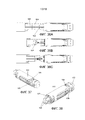
на фиг. 3 представлен трехмерный вид полного сборочного узла сердечного катетера, оснащенного устройством в соответствии с изобретением;in FIG. 3 is a three-dimensional view of the complete assembly of a cardiac catheter equipped with a device in accordance with the invention;
на фиг. 4 представлен трехмерный вид одного из вариантов осуществления устройства захвата створки клапана сердца в соответствии с изобретением от участка его проксимального конца, с захватывающим переднюю створку элементом в его положении захвата;in FIG. 4 is a three-dimensional view of one embodiment of a heart valve leaflet gripping device according to the invention from a portion of its proximal end, with an element capturing the front leaflet in its gripping position;
на фиг. 5 представлен трехмерный вид устройства с фиг. 4, но от участка его дистального конца;in FIG. 5 is a three-dimensional view of the device of FIG. 4, but from a portion of its distal end;
на фиг. 6 представлен вид сверху устройства с фиг. 4;in FIG. 6 is a top view of the device of FIG. 4;
на фиг. 7 представлен вид сбоку дополнительного варианта осуществления устройства захвата створки клапана сердца, которое по существу схоже с устройством с фиг. 4, но в котором захватывающие створку элементы содержат зазубрины или шипы;in FIG. 7 is a side view of a further embodiment of a heart valve leaflet gripping device that is substantially similar to the device of FIG. 4, but wherein the leaf-catching elements comprise notches or spikes;
на фиг. 8 представлен трехмерный вид с нижней стороны устройства с фиг. 4, показывающий захватывающий заднюю створку элемент в его положении захвата;in FIG. 8 is a three-dimensional view from the bottom of the device of FIG. 4, showing a gripping rear wing element in its gripping position;
на фиг. 9 представлен схематический вид сердца человека в разрезе, показывающий ретроградный доступ к митральному клапану посредством трансапикального доступа через верхушку сердца и левый желудочек;in FIG. 9 is a schematic sectional view of a human heart, showing retrograde access to the mitral valve through transapical access through the apex of the heart and the left ventricle;
на фиг. 10 представлен схематический вид сердца человека в разрезе, показывающий антеградный доступ к митральному клапану через левое предсердие;in FIG. 10 is a schematic sectional view of a human heart showing antegrade access to the mitral valve through the left atrium;
на фиг. 11 схематически представлен в последовательности от фиг. 11A до 11H различные этапы захвата двух створок митрального клапана;in FIG. 11 is schematically represented in the sequence of FIG. 11A to 11H different stages of capture of two cusps of the mitral valve;
на фиг. 12 представлен трехмерный вид упрощенного варианта осуществления устройства захвата створки клапана сердца, представленного на фиг. с 4 до 8;in FIG. 12 is a three-dimensional view of a simplified embodiment of a heart valve valve capture device of FIG. from 4 to 8;
на фиг. 13 представлен трехмерный вид с задней и дистальной стороны дополнительного варианта осуществления устройства захвата створки клапана сердца;in FIG. 13 is a three-dimensional view from the rear and distal sides of a further embodiment of a heart valve leaflet gripping device;
на фиг. 14 представлен трехмерный вид с передней и проксимальной стороны устройства, представленного на фиг. 13;in FIG. 14 is a three-dimensional view from the front and proximal sides of the device of FIG. thirteen;
на фиг. 15 представлен вид в сечении устройства, представленного на фиг. 13 и 14;in FIG. 15 is a sectional view of the device of FIG. 13 and 14;
на фиг. 16 представлен трехмерный вид с задней и дистальной стороны дополнительного варианта осуществления устройства захвата створки клапана сердца, в котором две части зонда могут скользить относительно друг друга для того, чтобы корректировать продольное положение захватывающих створку элементов;in FIG. 16 is a three-dimensional view from the rear and distal sides of a further embodiment of the heart valve leaflet gripping device, in which two probe parts can slide relative to each other in order to adjust the longitudinal position of the leaflet gripping elements;
на фиг. 17 представлен вид с торца устройства, представленного на фиг. 16, где оба захватывающих створку элемента находятся в их отведенном положении;in FIG. 17 is an end view of the apparatus of FIG. 16, where both sash-gripping members are in their retracted position;
на фиг. 18 представлен вид сбоку устройства, представленного на фиг. 16;in FIG. 18 is a side view of the device of FIG. sixteen;
на фиг. 19 представлен вид в разрезе дополнительного варианта осуществления устройства захвата створки клапана сердца, в котором захватывающие створку элементы естественно принимают положение захвата и устройство содержит скользящий по оси кожух для перемещения захватывающих элементов из положения захвата в отведенное положение;in FIG. 19 is a cross-sectional view of a further embodiment of a heart valve leaflet gripping device in which leaflet gripping elements naturally assume a gripping position and the device comprises an axially sliding casing for moving the gripping elements from the gripping position to the retracted position;
на фиг. 20 представлен вид сверху устройства, представленного на фиг. 19;in FIG. 20 is a plan view of the apparatus of FIG. nineteen;
на фиг. 21 представлен трехмерный вид дополнительного варианта осуществления устройства захвата створки клапана сердца, схожего с устройством, представленным на фиг. 19, при условии, что в этом варианте осуществления устройство дополнительно содержит элементы натяжения для того, чтобы перемещать захватывающие элементы в отведенное положение;in FIG. 21 is a three-dimensional view of a further embodiment of a heart valve leaflet gripping device similar to the device of FIG. 19, provided that in this embodiment, the device further comprises tension elements in order to move the gripping elements to the retracted position;
на фиг. 22 представлен трехмерный вид дополнительного варианта осуществления устройства захвата створки клапана сердца, в котором одну диаметральную половину внешнего кожуха для закрывания захватывающих створку элементов можно перемещать по оси относительно другой;in FIG. 22 is a three-dimensional view of a further embodiment of a heart valve leaflet gripping device in which one diametrical half of the outer casing for closing the leaflet-gripping elements can be axially moved relative to another;
на фиг. 23 представлено сечение устройства, представленного на фиг. 22, по линии A:A;in FIG. 23 is a sectional view of the device of FIG. 22, along line A: A;
на фиг. 24 представлен трехмерный вид дополнительного варианта осуществления устройства захвата створки клапана сердца, где устройство содержит два диаметрально противоположных ползуна, которые можно перемещать по оси друг относительно друга, и захватывающие створку элементы выходят из ползунов;in FIG. 24 is a three-dimensional view of an additional embodiment of a heart valve leaflet gripping device, wherein the device comprises two diametrically opposite sliders that can be axially moved relative to each other, and the leaflet gripping elements exit the sliders;
на фиг. 25 представлен вид сбоку устройства, представленного на фиг. 24;in FIG. 25 is a side view of the device of FIG. 24;
на фиг. 26 представлено сечение устройства, представленного на фиг. 25, по линии B:B;in FIG. 26 is a sectional view of the device of FIG. 25, on the line B: B;
на фиг. 27 представлен вид сбоку дополнительного варианта осуществления устройства захвата створки клапана сердца, где устройство содержит два предсердных стопора, каждый из которых связан с захватывающим створку элементом;in FIG. 27 is a side view of a further embodiment of a heart valve leaflet capture device, wherein the device comprises two atrial stoppers, each of which is associated with an element folding the leaflet;
на фиг. 28 представлен схематический вид сердца человека в разрезе, показывающий использование устройства с фиг. 27 для того, чтобы захватывать створки митрального клапана, с захватывающими створку элементами и предсердными стопорами в положении захвата и рабочей конфигурации, соответственно;in FIG. 28 is a schematic sectional view of a human heart showing the use of the device of FIG. 27 in order to capture the mitral valve leaflets, with the leaf-catching elements and atrial stoppers in the gripping position and operating configuration, respectively;
на фиг. 29 представлен схематический вид сердца человека в разрезе, показывающий использование устройства с фиг. 27 для того, чтобы захватывать створки митрального клапана, с захватывающими створку элементами и предсердными стопорами в отведенном положении и нерабочей конфигурации, соответственно;in FIG. 29 is a schematic sectional view of a human heart showing the use of the device of FIG. 27 in order to capture the cusps of the mitral valve, with cusp-catching elements and atrial stoppers in the retracted position and inoperative configuration, respectively;
на фиг. 30 представлен трехмерный вид с передней и проксимальной стороны устройства, представленного на фиг. 27, где устройство используют для того, чтобы захватывать две створки клапана;in FIG. 30 is a three-dimensional view from the front and proximal sides of the device of FIG. 27, where the device is used to capture two valve flaps;
на фиг. 31 представлен трехмерный вид с задней и дистальной стороны устройства, представленного на фиг. 30;in FIG. 31 is a three-dimensional view from the rear and distal sides of the device of FIG. thirty;
на фиг. 32 представлен трехмерный вид с передней и проксимальной стороны устройства, представленного на фиг. 30, где захватывающие створку элементы и предсердные стопоры в отведенном положении и нерабочей конфигурации, соответственно, с выдвинутым внешним кожухом;in FIG. 32 is a three-dimensional view from the front and proximal sides of the device of FIG. 30, where the leaf-catching elements and atrial stoppers are in the retracted position and the inoperative configuration, respectively, with the outer casing extended;
на фиг. 33 представлен трехмерный вид с задней и дистальной стороны дополнительного варианта осуществления устройства захвата створки клапана сердца, где чресклапанный элемент можно выводить из зацепления с катетерным зондом с тем, чтобы фиксировать захваченные створки друг относительно друга;in FIG. 33 is a three-dimensional view from the rear and distal sides of a further embodiment of the heart valve leaflet gripping device, where the transvalvular element can be disengaged from the catheter probe so as to fix the captured leaflets relative to each other;
на фиг. 34 представлен частичный разборный вид устройства, представленного на фиг. 33, показывающий восстанавливающий штырь отдельно от чресклапанного элемента;in FIG. 34 is a partial partial view of the device of FIG. 33, showing a repair pin separately from the chresvalvany element;
на фиг. 35 представлен частичный разборный вид устройства, показывающий восстанавливающий штырь частично вставленным в чресклапанный элемент;in FIG. 35 is a partial collapsible view of a device showing a repair pin partially inserted into a valve member;
на фиг. с 36A до 36C представлена серия видов сверху, показывающих процедуру выведения чресклапанного элемента из зацепления с катетерным зондом;in FIG. from 36A to 36C, a series of top views are presented showing a procedure for disengaging a trans-valve element from engagement with a catheter probe;
на фиг. 37 представлен трехмерный вид с задней и дистальной стороны выведенного из зацепления чресклапанного элемента;in FIG. 37 is a three-dimensional view from the rear and distal sides of the disengaged trans-valve member;
на фиг. 38 представлен трехмерный вид с передней и проксимальной стороны выведенного из зацепления чресклапанного элемента;in FIG. 38 is a three-dimensional view from the front and proximal sides of the disengaged trans-valve element;
на фиг. 39 представлен схематический вид сердца человека в разрезе, показывающий использование чресклапанного элемента устройства, представленного на фиг. 33, для того, чтобы фиксировать две створки митрального клапана друг относительно друга;in FIG. 39 is a schematic sectional view of a human heart showing the use of a trans valve element of the device of FIG. 33, in order to fix the two cusps of the mitral valve relative to each other;
на фиг. 40 представлен трехмерный вид с задней и дистальной стороны выведенного из зацепления чресклапанного элемента, представленного на фиг. 39;in FIG. 40 is a three-dimensional view from the rear and distal sides of the disengaged trans-valve member of FIG. 39;
на фиг. 41 представлен трехмерный вид с передней и проксимальной стороны выведенного из зацепления чресклапанного элемента, представленного на фиг. 39;in FIG. 41 is a three-dimensional view from the anterior and proximal sides of the disengaged trans-valve member of FIG. 39;
на фиг. 42 представлен частичный разборный вид с задней и дистальной стороны дополнительного варианта осуществления устройства захвата створки клапана сердца, где внешний кожух и захватывающие створку образования включают образования комплементарного прикрепления для того, чтобы закреплять внешний кожух на чресклапанном элементе;in FIG. 42 is a partial, exploded view from the rear and distal sides of a further embodiment of the heart valve leaf capture device, wherein the outer casing and the flap-forming structures include complementary attachments to secure the outer casing to the valve member;
на фиг. 43 представлен частичный разборный вид с задней и дистальной стороны дополнительного варианта осуществления устройства захвата створки клапана сердца, где внешний кожух и захватывающие створку образования включают образования комплементарного прикрепления;in FIG. 43 is a partial, exploded view from the rear and distal sides of a further embodiment of a heart valve leaf capture device, wherein the outer casing and leaf-catching formations include complementary attachment formations;
на фиг. 44 представлен частичный разборный вид с задней и дистальной стороны дополнительного варианта осуществления устройства захвата створки клапана сердца, где внешний кожух и захватывающие створку образования включают образования комплементарного прикрепления;in FIG. 44 is a partial, exploded view from the rear and distal sides of a further embodiment of a heart valve leaf capture device, wherein the outer casing and leaf-catching formations include complementary attachment formations;
на фиг. 45 представлен трехмерный вид с задней и дистальной стороны дополнительного варианта осуществления устройства захвата створки клапана сердца, где устройство содержит прокалывающий элемент с тем, чтобы прокалывать захваченные створки и фиксировать их друг относительно друга;in FIG. 45 is a three-dimensional view from the rear and distal sides of a further embodiment of the heart valve leaflet capture device, wherein the device comprises a piercing element so as to pierce the captured leaflets and fix them relative to each other;
на фиг. 46 представлено устройство, представленное на фиг. 45, в котором захватывающие створку элементы и предсердные стопоры находятся в положении захвата и рабочей конфигурации, соответственно, с блокировочными элементами, закрепленными на захватывающих створку элементах, и прокалывающим элементом, перемещенным дистально от чресклапанного элемента;in FIG. 46 shows the device of FIG. 45, wherein the leaf-catching elements and atrial stoppers are in a gripping position and a working configuration, respectively, with locking elements secured to the leaf-catching elements and a piercing element displaced distally from the chresvalvular element;
на фиг. 47 представлено устройство, представленное на фиг. 45 и 46, в котором предсердные стопоры находятся в нерабочей конфигурации с захватывающими створку элементами в их положении захвата с прокалывающими деталями прокалывающего элемента, зацепляющими блокировочные элементы;in FIG. 47 shows the device of FIG. 45 and 46, wherein the atrial stoppers are inoperative with the leaf-catching elements in their grip position with the piercing elements of the piercing element engaging the locking elements;
на фиг. 48 представлен трехмерный вид одного из вариантов осуществления прокалывающего элемента и блокировочных элементов, подлежащих использованию с устройством, представленным на фиг. с 45 до 47;in FIG. 48 is a three-dimensional view of one embodiment of the piercing element and the locking elements to be used with the device of FIG. from 45 to 47;
на фиг. 49 представлен трехмерный вид прокалывающего элемента, представленного на фиг. 48;in FIG. 49 is a three-dimensional view of the piercing member of FIG. 48;
на фиг. 50 представлен трехмерный вид блокировочного элемента, представленного на фиг. 48;in FIG. 50 is a three-dimensional view of the locking element of FIG. 48;
на фиг. 51 представлен альтернативный вариант осуществления устройства захвата створки клапана сердца, который содержит прокалывающий элемент для того, чтобы прокалывать захваченные створки, где прокалывающие детали расположены радиально наружу от дистального конца устройства;in FIG. 51 illustrates an alternative embodiment of a heart valve leaflet gripping device that includes a piercing element for piercing the captured leaflets, where the piercing parts are located radially outward from the distal end of the device;
на фиг. 52 представлен схематический вид сердца человека в разрезе, показывающий использование прокалывающего элемента, представленного на фиг. 48, для того, чтобы фиксировать две створки митрального клапана друг относительно друга; иin FIG. 52 is a schematic sectional view of a human heart showing the use of the piercing element shown in FIG. 48, in order to fix the two cusps of the mitral valve relative to each other; and
на фиг. с 53A до 53C представлена серия видов спереди и сзади створок митрального клапана, где прокалывающий элемент, представленный на фиг. 48, используют для того, чтобы фиксировать две створки друг относительно друга.in FIG. 53A to 53C show a series of front and rear views of the mitral valve cusps, where the piercing element shown in FIG. 48 are used to fix two flaps relative to each other.
ПОДРОБНОЕ ОПИСАНИЕ СО ССЫЛКОЙ НА ФИГУРЫDETAILED DESCRIPTION WITH REFERENCE TO FIGURES
На фиг. 1 чертежей показано сердце (10) человека, которое имеет левое предсердие (12) и левый желудочек (14), соединенные митральным клапаном (16), который имеет заднюю створку (18) и переднюю створку (20), и аортальный клапан (22) в качестве выпуска из левого желудочка (14). Левый желудочек (14) доступен для ретроградной трансапикальной процедуры через верхушку (24) сердца (10) известным образом с помощью устройства (26) в соответствии с изобретением. Конечно, в другом варианте осуществления устройство в соответствии с изобретением также можно использовать для процедуры антеградного доступа через левое предсердие, как известно в данной области.In FIG. 1 of the drawings shows a human heart (10) that has a left atrium (12) and a left ventricle (14) connected by a mitral valve (16), which has a posterior valve (18) and anterior valve (20), and an aortic valve (22) as a release from the left ventricle (14). The left ventricle (14) is accessible for a retrograde transapical procedure through the apex (24) of the heart (10) in a known manner using the device (26) in accordance with the invention. Of course, in another embodiment, the device in accordance with the invention can also be used for antegrade access procedure through the left atrium, as is known in the art.
Просто с целью полноты, полный сборочный узел (50) сердечного катетера в соответствии с изобретением проиллюстрирован на фиг. 3. В этом случае, линии (52) давления предусмотрены для соединения преобразователь (не показано) с воспринимающими давление портами (54) внутри зонда (56) по изобретению. Проксимальный конец (58) сборочного узла (50) имеет приводящий в действие элемент в форме ручки (60) или другого интерфейса клинициста. Система (62) прохождения или доставки катетера может быть жесткой, изогнутой, извилистой гибкой или направляемой и выполненной с возможностью вставляться в сердце пациента через подходящие пути доступа, такие как верхушка сердца, или транссептально или через путь доступа через бедро.Just for the sake of completeness, the complete assembly (50) of a cardiac catheter in accordance with the invention is illustrated in FIG. 3. In this case, pressure lines (52) are provided for connecting a transducer (not shown) to pressure sensing ports (54) inside the probe (56) of the invention. The proximal end (58) of the assembly (50) has a driving element in the form of a handle (60) or other clinician interface. The catheter passage or delivery system (62) may be rigid, curved, tortuous, flexible or guided and configured to be inserted into the patient’s heart through appropriate access paths, such as the apex of the heart, or transeptally or through the access path through the thigh.
Зонд (56) помещают во вмещающий элемент (64), который может помогать при расположении зонда (56) правильно по отношению к окружающим анатомическим структурам сердца. В варианте осуществления, проиллюстрированном на фиг. 3, вмещающий элемент (64) можно направлять через манипуляции и/или приведение в действие ручки (60) с тем, чтобы правильно располагать зонд по отношению к окружающим анатомическим структурам. В альтернативном варианте осуществления вмещающий элемент может представлять собой систему механического крепления, выполненную с возможностью располагать устройство захвата или зонд (56) относительно конкретных окружающих анатомических структур, образуя контакт с конкретными частями окружающих анатомических структур.The probe (56) is placed in the containing element (64), which can help with the location of the probe (56) correctly in relation to the surrounding anatomical structures of the heart. In the embodiment illustrated in FIG. 3, the containing element (64) can be guided through manipulations and / or actuation of the handle (60) so as to correctly position the probe relative to the surrounding anatomical structures. In an alternative embodiment, the enclosing member may be a mechanical fastening system configured to position the gripper or probe (56) relative to specific surrounding anatomical structures, forming contact with specific parts of the surrounding anatomical structures.
На фиг. с 4 до 8 проиллюстрирован один из вариантов осуществления устройства (100) захвата створки в соответствии с изобретением. Устройство (100) содержит сердечный катетер в форме зонда (102), имеющего проксимальный конец (104) и дистальный конец (106), оканчивающийся в чресклапанном элементе (108), выполненном с возможностью проходить через клапан сердца, в этом варианте осуществления митральный клапан, плоскость кольца которого в целом перпендикулярна продольной оси катетера. Чресклапанный элемент (108) имеет два захватывающих створку элемента (110), каждый из которых можно индивидуально перемещать под действием связанного приводного механизма, который в этом варианте осуществления содержит пару продольно перемещаемых изгибающихся элементов (112), между радиально отведенным положением, как показано в нижней или задней половине на фиг. 7, в котором его отдаляют по отношению к чресклапанному элементу (108), и положением захвата, как показано в верхней или передней половине с фиг. 7, в котором он отклоняется наружу под острым углом от чресклапанного элемента (108). Вдобавок и как показано на фиг. 7, на захватывающих створку элементах (110) могут быть предусмотрены направленные внутрь зазубрины или шипы (114), разработанные для того, чтобы гарантировать, что захватывающий элемент (110) остается в зацеплении, когда это желательно. Зазубрины (114) предпочтительно разрабатывают для того, чтобы иметь такой угол контакта со створками, чтобы они могли высвобождать створки, когда это желательно. Конечно, следует принимать во внимание, что присутствие или отсутствие таких зазубрин зависит от конкретной функции, которую должно осуществлять устройство (100).In FIG. 4 to 8 illustrate one embodiment of a sash gripping device (100) in accordance with the invention. The device (100) comprises a cardiac catheter in the form of a probe (102) having a proximal end (104) and a distal end (106) ending in a trans-valve element (108) configured to pass through a heart valve, in this embodiment, a mitral valve, the plane of the ring of which is generally perpendicular to the longitudinal axis of the catheter. The valve element (108) has two leaf-catching elements (110), each of which can be individually moved by a coupled drive mechanism, which in this embodiment comprises a pair of longitudinally movable bending elements (112), between a radially retracted position, as shown in the bottom or back half in FIG. 7, in which it is moved away with respect to the chresvalve element (108), and the grip position, as shown in the upper or front half of FIG. 7, in which it deviates outward at an acute angle from the chresvalvany element (108). In addition and as shown in FIG. 7, inwardly-engaged notches or spikes (114) may be provided on sash-gripping members (110), designed to ensure that the gripping member (110) remains engaged when desired. The notches (114) are preferably designed so as to have a contact angle with the flaps so that they can release the flaps when desired. Of course, it should be taken into account that the presence or absence of such notches depends on the specific function that the device (100) should perform.
В проиллюстрированном варианте осуществления два захватывающих створку элемента (110) располагают на диаметрально противоположных сторонах чресклапанного элемента (108) с тем, чтобы каждая в своем положении захвата формировала сходящуюся зону (116) захвата, направленную к краю створок клапана.In the illustrated embodiment, two leaf-catching elements (110) are positioned on diametrically opposite sides of the valve-shaped element (108) so that each in its gripping position forms a converging gripping zone (116) directed toward the edge of the valve flaps.
Направление, в котором захватывающие створку элементы идут в положении захвата, зависит от типа процедуры, в которой устройство подлежит использованию. Таким образом, в случае, проиллюстрированном на фиг. 9, устройство захвата створки митрального клапана выполнено с возможностью использования в обратной процедуре, такой как трансапикальная или трансаортальная процедура, и в этом случае сходящаяся зона (116) захвата, сформированная захватывающими створку элементами (110), направлена к дистальному концу (106) устройства, причем поворотный или гнущийся участок средств захват располагают ближе к проксимальному концу устройства.The direction in which the sash-gripping elements go in the grip position depends on the type of procedure in which the device is to be used. Thus, in the case illustrated in FIG. 9, the mitral valve leaf capture device is adapted to be used in a reverse procedure, such as a transapical or transaortic procedure, in which case the converging capture zone (116) formed by the leaf-catching elements (110) is directed toward the distal end (106) of the device, moreover, the swivel or bendable portion of the gripping means is located closer to the proximal end of the device.
С другой стороны, если устройство подлежит использованию в антеградной процедуре, как показано на фиг. 10, такой как транссептальная процедура, например, с использованием стандартных путей доступа, таких как бедренные вены, наряду со стандартными способами чрескожного доступа к левому предсердию через межпредсердную перегородку или чреспредсердную процедуру, то захватывающие створку элементы (110) должны быть направлены в противоположном направлении по отношению к чресклапанному элементу или дистальному концу (106) устройства, но в том же направлении по отношению к клапану сердца, при правильной ориентации внутри сердца, что совершенно ясно специалисту в данной области.On the other hand, if the device is to be used in an antegrade procedure, as shown in FIG. 10, such as a transeptal procedure, for example, using standard access pathways such as the femoral veins, along with standard methods for transdermal access to the left atrium via the atrial septum or atrial procedure, the sash-trapping elements (110) should be directed in the opposite direction in with respect to the transcranial element or the distal end (106) of the device, but in the same direction with respect to the heart valve, with the correct orientation inside the heart, which is completely clear those skilled in the art.
В варианте осуществления, проиллюстрированном на фиг. с 4 до 8, пара продольно перемещаемых изгибающихся элементов (112) имеет форму проволок, которые могут иметь круглую, квадратную, овальную, прямоугольную или другую многоугольную форму поперечного сечения, которая может варьировать вдоль длины элемента (112). Изгибающиеся элементы (112) можно продольно перемещать от проксимального конца (104) катетера (102), и они ограничены с тем, чтобы они могли изгибаться латерально наружу при достаточной сжимающей нагрузке для того, чтобы перемещать связанный захватывающий створку элемент (110) между его радиально отведенным положением и его положением захвата. Изгибающиеся элементы (112) можно подавать или пропускать через отверстия (118) в чресклапанном элементе (108) и в захватывающих створку элементах (110), так что изгибающиеся элементы (112) определяют местоположение захватывающих створку элементов (110) относительно чресклапанного элемента (108).In the embodiment illustrated in FIG. from 4 to 8, a pair of longitudinally movable bending elements (112) has the shape of wires, which may have a round, square, oval, rectangular or other polygonal cross-sectional shape, which may vary along the length of the element (112). The bending elements (112) can be longitudinally moved from the proximal end (104) of the catheter (102), and they are limited so that they can bend laterally outward with sufficient compressive load in order to move the associated leaf-catching element (110) between its radially allotted position and its capture position. Curving elements (112) can be fed or passed through openings (118) in the valve element (108) and in the leaf-catching elements (110), so that the curving elements (112) determine the location of the leaf-catching elements (110) relative to the valve valve element (108) .
Кроме того, в проиллюстрированном варианте осуществления захватывающие створку элементы (110) прикрепляют к чресклапанному элементу (108) посредством шарниров (120) приблизительно в положении, где захватывающие створку элементы (110) соединяют чресклапанный элемент (108) с тем, чтобы их можно было свободно перемещать между отведенным положением и положением захвата. Соответственно, захватывающие створку элементы (110) ограничены в перемещении под углом, чтобы следовать за латерально перемещаемыми частями изгибающихся элементов (112), к которым их прикрепляют приблизительно по середине вдоль длины захватывающих створку элементов (110). Предполагают, что изгибающиеся элементы (112) можно выполнять из сверхэластичного сплава/сплава с памятью геометрической формы, такого как нитинол или другой материал, имеющий схожие свойства.In addition, in the illustrated embodiment, the leaf-catching elements (110) are attached to the trans-valve element (108) by hinges (120) at a position where the leaf-catching elements (110) connect the trans-valve element (108) so that they can freely move between the retracted position and the grip position. Accordingly, the sash-gripping elements (110) are limited in angular movement to follow the laterally movable parts of the bending elements (112) to which they are attached approximately midway along the length of the sash-gripping elements (110). It is believed that the bending elements (112) can be made of a superelastic alloy / geometric shape memory alloy such as nitinol or other material having similar properties.
На фиг. с 11A до 11H проиллюстрирована последовательность этапов захвата двух створок (150, 152) митрального клапана (154) с использованием одного из вариантов осуществления устройства (156) захвата створки в соответствии с изобретением. На фиг. представлена способность захватывающих створку элементов (158) индивидуально открываться и закрываться или перемещаться из положения захвата в отведенное положение, и наоборот. Кроме того, в проиллюстрированном варианте осуществления захватывающие створку элементы (158) способны к перемещению в осевом направлении индивидуально. Ценно, что индивидуальное движение захватывающих элементов (158) делает возможным индивидуальный захват створки и затем приведение захваченных створок в соприкосновение прежде их фиксации друг относительно друга.In FIG. from 11A to 11H, the sequence of steps for capturing two mitral valve flaps (150, 152) of the mitral valve (154) is illustrated using one embodiment of the flap capture device (156) in accordance with the invention. In FIG. The ability of the elements capturing the sash (158) to individually open and close or move from the gripping position to the retracted position, and vice versa, is presented. In addition, in the illustrated embodiment, the leaf-catching elements (158) are capable of axial movement individually. It is valuable that the individual movement of the gripping elements (158) makes it possible to individually capture the flaps and then bring the captured flaps into contact before they are fixed relative to each other.
На фиг. 11A и 11B оба захватывающих створку элемента (158) находятся в отведенном положении, в которое они отведены по отношению к чресклапанному элементу (160), так что зонд (162) является приблизительно трубчатым во время приближения к двум створкам (150, 152) митрального клапана (154). Как показано на фиг. с 11C до 11E, один из захватывающих створку элементов (158), в этом случае захватывающий переднюю створку элемент, можно открывать в его положение захвата, причем другой захватывающий элемент (158) остается в своем отведенном положении. Поскольку захватывающие элементы (158) способны к перемещению по оси независимо друг от друга, захватывающий переднюю створку элемент можно перемещать с тем, чтобы лучше располагать по отношению к передней створке (150) и так, что его затем можно приводить в его отведенное положение, как показано на фиг. 11E, тем самым захватывая створку (150). Когда створка захвачена, в этом случае передняя створка (150), второй захватывающий створку элемент (158) перемещают в его положение захвата створки, как показано на фиг. 11F. Фиг. с 11F до 11H схожи с фиг. с 11C до 11E, за исключением того, что в этом случае захватывают заднюю створку (152). Кроме того, перед захватом задней створки (152) захватывающий заднюю створку элемент (158) перемещают по оси с тем, чтобы гарантировать, что створку (152) захватывают в положении, которое подходит по отношению к передней створке (150).In FIG. 11A and 11B, both sash-gripping members (158) are in the retracted position in which they are retracted relative to the valve member (160), so that the probe (162) is approximately tubular when approaching the two mitral valve cusps (150, 152) (154). As shown in FIG. from 11C to 11E, one of the leaf-catching elements (158), in which case the front-leaf-catching element, can be opened in its gripping position, with the other gripping element (158) remaining in its retracted position. Since the gripping elements (158) are able to move along the axis independently of each other, the gripping front sash can be moved so as to be better positioned relative to the front sash (150) and so that it can then be brought into its retracted position, as shown in FIG. 11E, thereby gripping the sash (150). When the leaf is captured, in this case, the front leaf (150), the second leaf-catching element (158) are moved to its leaf grip position, as shown in FIG. 11F. FIG. from 11F to 11H are similar to FIG. from 11C to 11E, except that in this case they capture the rear wing (152). In addition, before capturing the rear leaf (152), the rear leaf catching element (158) is axially moved to ensure that the leaf (152) is gripped in a position that is suitable with respect to the front leaf (150).
В пораженных или патологических клапанах, а также и в естественной ситуации, преобладает такое состояние, что свободный край створок митрального клапана выстраивается на одном и том же расстоянии от митрального кольца, и это может представлять собой случай, когда передняя створка слегка длиннее, чем задняя створка, и, таким образом, заходит дальше от митральной плоскости или кольца. По этой причине важно, чтобы два захватывающих элемента устройства можно было индивидуально перемещать по оси относительно зонда.In diseased or pathological valves, as well as in a natural situation, such a condition prevails that the free edge of the mitral valve cusps is aligned at the same distance from the mitral ring, and this may be the case when the anterior leaflet is slightly longer than the posterior leaflet , and thus goes further from the mitral plane or ring. For this reason, it is important that the two gripping elements of the device can be individually moved axially relative to the probe.
Конечно, ценно, что независимо от выполняемой процедуры, таким образом, будь она ретроградной или антеградной, процедура захвата створки будет одной и той же, как описано выше. Дополнительный альтернативный подход будет состоять в прохождении устройства через аортальный клапан, выполнении резкого поворота внутри левого желудочка и затем продолжении через митральный клапан. В этом случае, можно использовать такие пути доступа, как бедренные артерии.Of course, it is valuable that regardless of the procedure being performed, thus, whether it is retrograde or antegrade, the procedure for capturing the sash will be the same as described above. An additional alternative approach would be to pass the device through the aortic valve, perform a sharp turn inside the left ventricle, and then continue through the mitral valve. In this case, access paths such as the femoral arteries can be used.
На фиг. 12 проиллюстрирован дополнительный вариант осуществления устройства (200) захвата створки в соответствии с изобретением, в котором изгибающийся элемент (202) принимает форму одной проволоки.In FIG. 12 illustrates an additional embodiment of a sash gripping device (200) according to the invention, in which the bending element (202) takes the form of a single wire.
На фиг. с 13 до 15 проиллюстрирован еще один дополнительный вариант осуществления устройства (250) захвата створки в соответствии с изобретением. В этом варианте осуществления захватывающие створку элементы (252) соединяют с частью (254), также обозначаемой как гибкий шарнир, которую фиксируют относительно чресклапанного элемента (256) посредством интегральной соединительной зоны (258), которая является гибкой или деформируемой за счет щелей, канавок в материале или выполнения иным образом с возможностью позволять перемещение захватывающих створку элементов (252) между их отведенными положениями и их положениями захвата. Изгибающийся элемент (260) представлен в форме одной проволоки, но можно использовать какой-либо другой подходящий изгибающийся элемент, например, две проволоки или тому подобное.In FIG. from 13 to 15, another additional embodiment of the sash gripping device (250) according to the invention is illustrated. In this embodiment, the leaf-catching elements (252) are connected to a part (254), also referred to as a flexible hinge, which is fixed relative to the valve element (256) by means of an integral connecting zone (258), which is flexible or deformable due to slots, grooves in material or performing otherwise with the ability to allow movement of the sash-gripping elements (252) between their allotted positions and their gripping positions. The bending element (260) is in the form of a single wire, but any other suitable bending element, for example, two wires or the like, can be used.
Будет благоприятно, если устройство захвата будет способно захватывать каждую створку на правильном расстоянии от митральной плоскости или кольца, которое является специфичным для каждой створки. Аналогичным образом, может быть более благоприятно независимо перемещать створку после ее захвата. Это может быть необходимо для пролапсирующих створок, которые захвачены в положении, которое является субоптимальным для восстановления и где перемещение такой створки по оси относительно другой створки после захвата будут улучшать смыкание клапана. Когда створки выровнены до оптимального положения по оси друг относительно друга и/или относительно митральной плоскости или кольца, можно осуществлять восстановление. Независимого осевого приведения в движение каждого захватывающего створку элемента можно достигать посредством его установки на ползун или перемещаемый элемент, как проиллюстрировано на фиг. с 16 до 18.It will be beneficial if the capture device is capable of capturing each leaf at the correct distance from the mitral plane or ring, which is specific to each leaf. Similarly, it may be more favorable to independently move the sash after it has been gripped. This may be necessary for prolapsing flaps that are locked in a position that is suboptimal for recovery and where moving the flap axially relative to the other flap after gripping will improve valve closure. When the flaps are aligned to the optimal position along the axis relative to each other and / or relative to the mitral plane or ring, recovery can be carried out. Independent axial propulsion of each sash-gripping member can be achieved by mounting it on a slider or movable member, as illustrated in FIG. from 16 to 18.
Кроме того, поскольку устройство допускает движение захваченных створок друг относительно друга, положение оптимального выравнивания створок можно определять перед осуществлением процедуры восстановления. Таким образом, перед осуществлением процедуры восстановления захваченные створки можно перемещать друг относительно друга и с применением известных способов, таких как эхокардиография, флуороскопия, перепады давления и т. п., можно определять положение оптимального выравнивания створки. Когда оптимальное положение определено, процедуру восстановления можно осуществлять с тем, чтобы удерживать створки в оптимальном положении, которое определили.In addition, since the device allows the movement of the captured flaps relative to each other, the position of the optimal alignment of the flaps can be determined before the recovery procedure. Thus, before performing the recovery procedure, the captured leaflets can be moved relative to each other and using known methods such as echocardiography, fluoroscopy, pressure drops, etc., it is possible to determine the position of the optimal alignment of the leaflet. When the optimal position is determined, the recovery procedure can be carried out in order to keep the flaps in the optimal position that was determined.
На фиг. с 16 до 18 проиллюстрирован такой дополнительный вариант осуществления устройства (280) захвата створки, в котором каждый из захватывающих створку элементов (282) несет отдельная продольно перемещаемая получасть (284) или ползун зонда (286) с тем, чтобы можно было корректировать продольные положения двух захватывающих створку элементов (282) друг относительно друга по мере необходимости для того, чтобы располагать требуемую часть одной из створок митрального клапана относительно другой. Как показано на фиг. 17, межсоединение может иметь форму (288) поперечного сечения по типу ласточкиного хвоста, допускающего относительное продольное движение двух частей (284). Следует принимать во внимание, что посредством перемещения получасти (284) или ползуна в осевом направлении, можно менять положение захватывающего створку элемента (282) по оси до правильной глубины для захвата створки. Как вариант, когда створки захвачены, ползуны можно перемещать по оси с тем, чтобы располагать створки друг относительно друга перед их фиксацией. Поскольку каждый ползун может перемещаться по оси независимо от другого, возможно перемещать каждый захватывающий створку элемент в осевом направлении независимо от другого.In FIG. from 16 to 18, such an additional embodiment of a sash gripping device (280) is illustrated in which each of the sash gripping elements (282) carries a separate longitudinally movable half (284) or probe slider (286) so that the longitudinal positions of two capturing the leaflet elements (282) relative to each other as necessary in order to position the desired part of one of the leaflets of the mitral valve relative to the other. As shown in FIG. 17, the interconnect may be in the form of a (288) cross section in the form of a dovetail, allowing relative longitudinal movement of the two parts (284). It should be taken into account that by moving the half-piece (284) or the slider in the axial direction, it is possible to change the position of the sash-gripping element (282) along the axis to the correct depth for gripping the sash. Alternatively, when the flaps are gripped, the sliders can be moved along the axis so as to position the flaps relative to each other before their fixation. Since each slider can move along the axis independently of the other, it is possible to move each leaf-catching element in the axial direction independently of the other.
Захватывающие створку элементы (300), конечно, также можно выполнять с возможностью принимать положение захвата в качестве их естественного положения в отсутствие каких-либо усилий, прикладываемых к ним, как лучше всего проиллюстрировано на фиг. с 19 до 20. В этом случае приводной механизм может содержать продольно перемещаемый внешний кожух (302), который входит в зацепление с захватывающими створку элементами (300) с тем, чтобы перемещать их против естественного смещения из положения захвата в направлении их отведенных положений. Для того чтобы позволить индивидуально активировать захватывающие створку элементы (300), захватывающие створку элементы (300) предусмотрены на отдельных кожухах (304, 306), один кожух (304) скользит внутри другого кожуха (306). Это позволяет перемещать захватывающие створку элементы (300) по оси друг относительно друга с тем, чтобы сдвигать их вдоль длины чресклапанного элемента (308). Это позволяет вводить первый в зацепление в первом случае посредством предварительно определяемого движения внешнего кожуха (302) на внешней поверхности зонда и вводить второй в зацепление впоследствии вследствие дополнительного движения внешнего кожуха (302). Между последовательным зацеплением захватывающих створку элементов с помощью кожуха, подходящие манипуляции можно осуществлять для того, чтобы корректировать положения захватывающих створку элементов друг относительно друга, и также можно добиваться независимого изменения положения захваченных створок.The leaf-gripping elements (300), of course, can also be configured to take the gripping position as their natural position in the absence of any force exerted on them, as best illustrated in FIG. from 19 to 20. In this case, the drive mechanism may include a longitudinally movable outer casing (302), which engages with the elements catching the sash (300) so as to move them against natural displacement from the capture position in the direction of their allotted positions. In order to enable individually activating leaf-catching elements (300), leaf-catching elements (300) are provided on separate casings (304, 306), one casing (304) slides inside another casing (306). This allows you to move the sash-gripping elements (300) along the axis relative to each other so as to shift them along the length of the valve valve element (308). This allows the first to be engaged in the first case by the predetermined movement of the outer casing (302) on the outer surface of the probe and to enter the second into the engagement subsequently due to the additional movement of the outer casing (302). Between the successive engagement of the leaf-catching elements with the help of a casing, suitable manipulations can be carried out in order to adjust the positions of the leaf-catching elements relative to each other, and it is also possible to achieve an independent change in the position of the captured leafs.
Кроме того, на фиг. 19 и 20 проиллюстрировано, что можно предусмотреть два отдельных воспринимающих давление порта (310), один на передней стороне чресклапанного элемента (308) и другой на его противоположной стороне. Использование воспринимающих давление портов (310) позволяет использовать устройство без обязательно требуемого сложного аппарата визуализации, и предусмотрено, что мониторинг давления, прикладываемого к дистальному концу зонда, посредством портов (310) является всем, что необходимо благодаря разности давлений в левом желудочке и левом предсердии и способности осуществлять мониторинг положений створок с использованием давления. Кроме того, порты можно использовать для того, чтобы определять, расположено ли устройство должным образом внутри клапана так, что створки будут закрывать соответствующие им порты во время закрывания клапана, тем самым вызывая изменение давления, подлежащее измерению. Дополнительно это описано более подробно далее. Также один или оба порта можно использовать для того, чтобы подавать вакуум на створку, следовательно, если это будет удобно.In addition, in FIG. 19 and 20, it is illustrated that two separate pressure receiving ports (310) can be provided, one on the front side of the valve member (308) and the other on its opposite side. The use of pressure sensing ports (310) allows the device to be used without the required complex visualization apparatus, and it is envisaged that monitoring the pressure applied to the distal end of the probe through the ports (310) is all that is necessary due to the pressure difference in the left ventricle and the left atrium and Ability to monitor leaf positions using pressure. In addition, the ports can be used to determine whether the device is properly positioned inside the valve so that the flaps will close their corresponding ports while the valve is closing, thereby causing a pressure change to be measured. This is further described in more detail below. Also, one or both ports can be used to supply vacuum to the leaf, therefore, if it is convenient.
Важно отметить, что когда используют скользящий кожух, нужно предусмотреть подходящий вырез (312) в кожухе с тем, чтобы вмещать створки после захвата.It is important to note that when using a sliding cover, a suitable cut-out (312) must be provided in the cover in order to accommodate the flaps after gripping.
Конечно, ценно, что для помощи или взамен внешнего кожуха (302), элемент натяжения, такой как вытяжная проволока (314), как проиллюстрировано на фиг. 21, можно предусмотреть для того, чтобы перемещать захватывающие створку элементы в направлении их отведенных положений.Of course, it is valuable that, for help or in exchange for the outer casing (302), a tension member such as a draw wire (314), as illustrated in FIG. 21 may be provided in order to move the leaf-catching elements in the direction of their allotted positions.
В еще одном дополнительном альтернативном варианте осуществления и как проиллюстрировано на фиг. 22, зонд может иметь продольно скользящий внешний полукожух (316) на каждой стороне зонда с тем, чтобы посредством продольного движения полукожуха можно было управлять захватывающими створку элементами независимо друг от друга. В связи с этим, на фиг. 23 проиллюстрирован один возможный способ соединения с возможностью скольжения для двух внешних полукожухов (316) и центрального зонда или чресклапанного элемента.In yet a further alternative embodiment, and as illustrated in FIG. 22, the probe may have a longitudinally sliding outer half-shell (316) on each side of the probe so that, through the longitudinal movement of the half-shell, it is possible to control the leaf-catching elements independently of each other. In this regard, in FIG. 23 illustrates one possible slip-connect method for two outer half-shells (316) and a central probe or trans-valve member.
На фиг. с 24 до 26 проиллюстрирован еще один дополнительный вариант осуществления устройства (350) захвата створки в соответствии с изобретением. В этом варианте осуществления, схожем с вариантом осуществления с фиг. 22 и 23, устройство (350) имеет два отдельных продольно скользящих ползуна (352), соединенных с зондом (354), причем захватывающий створку элемент (356) идет от каждого ползуна (352). В этом варианте осуществления захватывающие створку элементы (356) имеют естественное положение захвата, и их перемещают в отведенное положение посредством гибких элементов (358) натяжения. Элементы (358) натяжения могут быть ограничены в продольном направлении в канавках (360), предусмотренных во внешней поверхности зонда (354) и внутри ползунов (352). Кроме того, устройство (350) дополнительно содержит два параллельных просвета (362), которые сообщаются с портом (364), предусмотренным по обеим сторонам на дистальном конце зонда (354). Просветы (362), как описано выше, можно использовать или для датчиков давления или для вакуумной и/или всасывающей компоновки.In FIG. from 24 to 26, another additional embodiment of the sash gripping device (350) according to the invention is illustrated. In this embodiment, similar to the embodiment of FIG. 22 and 23, the device (350) has two separate longitudinally sliding sliders (352) connected to the probe (354), the sash gripping element (356) coming from each slide (352). In this embodiment, the sash-gripping elements (356) have a natural grip position and are moved to the retracted position by means of the flexible tensioning elements (358). The tension elements (358) may be longitudinally limited in grooves (360) provided in the outer surface of the probe (354) and inside the sliders (352). In addition, the device (350) further comprises two parallel lumens (362), which communicate with a port (364) provided on both sides at the distal end of the probe (354). Gaps (362), as described above, can be used either for pressure sensors or for a vacuum and / or suction assembly.
Следует принимать во внимание, что два воспринимающих давление порта (310, 364) и параллельные просветы (362) с фиг. с 19 до 20 и с 24 до 26 дополнительно могут выполнять функцию части системы подтверждения захвата створки. В одном из вариантов осуществления система может содержать преобразователи и мониторы вне пациента и обеспечивает клинициста обратной связью по давлению в форме волны в реальном времени, такой как сигналы давления, отображаемые на экране или мониторе. Например, посредством расположения воспринимающих давление портов так, что они лежат по оси на линии с захватывающими створку элементами, но радиально внутрь от них и, таким образом, внутри сходящейся зоны захвата, клиницист может захватывать створку так, что захватывающий створку элемент заставляет створку накрывать или закупоривать воспринимающий давление порт. Это создает четкое и заметное изменение сигнала давления, мониторинг которого осуществляют, например, сигнал давления типа «нерезонансная линия». Таким образом, может быть возможно подтверждать, что успешный захват створки имел место. Кроме того, следует принимать во внимание, что параллельные просветы могут функционировать полностью независимо друг от друга так, что измерения давления для каждого воспринимающего порта можно выполнять независимо. Это позволит осуществлять мониторинг сигнала давления для каждого захватывающего створку элемента индивидуально и, таким образом, получать сигнал давления типа «нерезонансная линия» для первой захваченной створки и затем после этого для второй или последующей захваченной створки.It will be appreciated that the two pressure sensing ports (310, 364) and the parallel gaps (362) of FIG. from 19 to 20 and from 24 to 26 can additionally perform the function of a part of the sash grip confirmation system. In one embodiment, the system may comprise transducers and monitors outside the patient and provides the clinician with real-time pressure feedback in the form of a wave, such as pressure signals displayed on a screen or monitor. For example, by arranging the pressure-receiving ports so that they lie axially on a line with elements that capture the leaflet, but radially inward from them and, thus, inside the converging gripping zone, the clinician can grab the leaflet so that the element catching the leaflet causes the leaflet to cover or clog pressure-sensitive port. This creates a clear and noticeable change in the pressure signal, the monitoring of which is carried out, for example, a pressure signal of the type "non-resonant line". Thus, it may be possible to confirm that successful sash capture has taken place. In addition, it should be appreciated that parallel gaps can function completely independently of each other so that pressure measurements for each receiving port can be performed independently. This allows you to monitor the pressure signal for each element capturing the leaflet individually and, thus, to receive a pressure signal of the type "non-resonant line" for the first captured leaflet and then after that for the second or subsequent captured leaflet.
С другой стороны и как описано выше, просветы и порты также можно использовать в качестве всасывающих или вакуумных портов. В этом случае, когда воспринимающие давление порты не закупорены створкой клапана, непрерывное всасывание необходимо для создания вакуума внутри одного или нескольких просветов. Однако после закупоривания порта давления створкой клапана, внутри параллельного просвета можно получать и поддерживать вакуум, который требует сниженного всасывания. Таким образом, посредством мониторинга всасывания, требуемого для создания определенного давления внутри просвета или посредством мониторинга давления внутри просвета при применяемом постоянном всасывании, можно получать заметное изменение в сигнале обратной связи, когда створка успешно захвачена.On the other hand, and as described above, gaps and ports can also be used as suction or vacuum ports. In this case, when the pressure receiving ports are not clogged by the valve leaf, continuous suction is necessary to create a vacuum inside one or more of the gaps. However, after clogging the pressure port with a valve flap, a vacuum can be obtained and maintained within the parallel lumen, which requires reduced suction. Thus, by monitoring the suction required to create a certain pressure inside the lumen or by monitoring the pressure inside the lumen with continuous suction applied, it is possible to obtain a noticeable change in the feedback signal when the sash is successfully captured.
На фиг. 27 проиллюстрирован еще один дополнительный вариант осуществления устройства (400) захвата створки в соответствии с изобретением. Подобно варианту осуществления, проиллюстрированном на фиг. с 19 до 20, два захватывающих створку элемента (402) имеют естественное положение захвата, и их можно перемещать против естественного смещения из положения захвата в направлении их отведенного положения посредством продольно перемещаемого внешнего кожуха (404). Кроме того, устройство (400) дополнительно содержит два предсердных стопора (406), каждый связан со взаимодействующим захватывающим створку элементом (402), которые расположены между захватывающими створку элементами (402) и чресклапанным элементом (408). Стопоры (406) можно индивидуально перемещать между нерабочей конфигурацией, в которой стопор (406) расположен в целом смежно с чресклапанным элементом (408), и рабочей конфигурацией, в которой стопор (406) отклоняется наружу под острым углом от чресклапанного элемента, как показано на фиг. 27. Движение стопоров (406) между рабочей и нерабочей конфигурациями возможно через работу связанного исполнительного механизма, который в этом варианте осуществления содержит пару продольно перемещаемых исполнительных элементов (410). Исполнительные элементы (410) способны изгибаться латерально с тем, чтобы перемещать связанный стопор (406) между его нерабочей конфигурацией и его рабочей конфигурацией.In FIG. 27 illustrates yet another additional embodiment of a sash gripping device (400) in accordance with the invention. Similar to the embodiment illustrated in FIG. from 19 to 20, two leaf-catching elements (402) have a natural gripping position and can be moved against a natural displacement from the gripping position in the direction of their retracted position by means of a longitudinally movable outer casing (404). In addition, device (400) further comprises two atrial stoppers (406), each associated with an interacting leaf-catching element (402), which are located between the leaf-catching elements (402) and the valve valve element (408). The stops (406) can be individually moved between a non-working configuration in which the stop (406) is generally adjacent to the valve member (408) and a working configuration in which the stop (406) deviates outward at an acute angle from the valve member, as shown in FIG. 27. The movement of the stoppers (406) between the working and non-working configurations is possible through the operation of the associated actuator, which in this embodiment contains a pair of longitudinally movable actuators (410). Actuators (410) are able to bend laterally so as to move the associated stopper (406) between its inoperative configuration and its operating configuration.
При использовании и как проиллюстрировано на фиг. с 28 до 29, когда используют в обратной процедуре, устройство (400) продвигают через желудочек (412) и в левое предсердие (414), пока чресклапанный элемент (408) не окажется внутри митрального клапана (416). На этом этапе внешний кожух (404) отдаляют по оси, вызывая перемещение захватывающих створку элементов (402) в их положение захвата. Когда положение створки (418) в отношении захватывающего створку элемента (402) определено, например, посредством датчиков давления, как описано выше, и определено, что створка (418) находится внутри сходящейся зоны захвата, определяемой захватывающим створку элементом (402), когда в положении захвата, тогда предсердный стопор (406) перемещают в рабочую конфигурацию с тем, чтобы располагать створку (418) между захватывающим створку элементом (402) и взаимодействующим стопором (406). Лучше всего это проиллюстрировано на фиг. 30 и 31. Когда обе створки (418) захвачены, внешний кожух (404) снова продвигают, как проиллюстрировано на фиг. 32, при этом одновременно перемещая предсердные стопоры (406) в их нерабочую конфигурацию через схлопывание продольно перемещаемых исполнительных элементов (410). Это позволяет надежно захватывать и удерживать на месте створки (418) между обоими захватывающими створку элементами (402) и внешним кожухом (404) и чресклапанным элементом (408). Кроме того, это позволяет тянуть створки (418) в направлении друг друга, тем самым уменьшая септо-латеральное расстояние и корректируя расширение кольца.In use and as illustrated in FIG. from 28 to 29, when used in the reverse procedure, the device (400) is advanced through the ventricle (412) and into the left atrium (414) until the transcranial element (408) is inside the mitral valve (416). At this stage, the outer casing (404) is moved away along the axis, causing the elements (402) capturing the leaf to move to their gripping position. When the position of the sash (418) with respect to the sash-gripping element (402) is determined, for example, by pressure sensors, as described above, and it is determined that the sash (418) is inside the converging grip zone detected by the sash-gripping element (402) when the grip position, then the atrial stop (406) is moved to the working configuration so as to position the leaf (418) between the leaf-catching member (402) and the interacting stop (406). This is best illustrated in FIG. 30 and 31. When both flaps (418) are engaged, the outer casing (404) is advanced again, as illustrated in FIG. 32, while simultaneously moving the atrial stoppers (406) to their inoperative configuration through the collapse of the longitudinally movable actuators (410). This makes it possible to reliably grip and hold in place the flaps (418) between the two flap gripping elements (402) and the outer casing (404) and the valve valve element (408). In addition, this allows the flaps (418) to be pulled in the direction of each other, thereby reducing the septo-lateral distance and correcting the expansion of the ring.
Конечно, ценно, что взамен использования продольно перемещаемых исполнительных элементов (410) для того, чтобы перемещать стопоры (406) между рабочей и нерабочей конфигурациями, стопоры также можно выполнять с возможностью естественно принимать рабочую конфигурацию, подобно захватывающим створку элементам. В таком случае стопоры можно перемещать в нерабочую конфигурацию через гибкий элемент натяжения, такой как вытяжная проволока, шнур, кабель или тому подобное. В таком случае стопоры будут удерживаться в нерабочей конфигурации посредством элемента натяжения до тех пор, пока не определят, что створка расположена внутри сходящейся зоны захвата. Когда определено, натяжение на элементе натяжения устраняют, вызывая перемещение элемента в рабочую конфигурацию и захват створки между захватывающим элементом и стопором.Of course, it is valuable that instead of using longitudinally movable actuating elements (410) in order to move the stoppers (406) between the working and non-working configurations, the stoppers can also be made with the possibility of naturally adopting a working configuration, similar to leaf-catching elements. In this case, the stoppers can be moved into an inoperative configuration through a flexible tensioning member, such as a draw wire, cord, cable or the like. In this case, the stoppers will be held in an inoperative configuration by means of a tensioning element until they determine that the sash is located inside the converging gripping zone. When determined, the tension on the tension element is removed, causing the element to move into the working configuration and the leaf to be caught between the gripping element and the stopper.
Кроме того, стопоры также можно перемещать по оси, например, используя ползуны или тому подобное, как показано на фиг. с 16 до 18. Ползуны позволяют выравнивать створки базо-апикально прежде, чем продвигать внешний кожух. Конечно, выравнивание створок также может иметь место, когда внешний кожух продвинут, в этом случае внешний кожух также должен быть разделен на два полукожуха.In addition, the stoppers can also be axially moved, for example using sliders or the like, as shown in FIG. from 16 to 18. The sliders allow you to align the valves basically apically before advancing the outer casing. Of course, alignment of the flaps can also occur when the outer casing is advanced, in which case the outer casing should also be divided into two half-shells.
На фиг. с 33 до 41 проиллюстрирован еще один дополнительный вариант осуществления устройства (500) захвата створки в соответствии с изобретением. Устройство (500) по существу схоже с устройством (400), проиллюстрированным на фиг. 27, при условии, что в этом варианте осуществления устройство (500) способно фиксировать две или больше захваченных створки друг относительно друга, тем самым реализуя процедуру восстановления по типу край в край. В проиллюстрированном варианте осуществления чресклапанный элемент (502) можно выводить из зацепления с катетерным зондом (504) и оставлять в положении внутри сердца с тем, чтобы фиксировать захваченные створки клапана друг относительно друга. В проиллюстрированном варианте осуществления зонд (504) и чресклапанный элемент (502) соединяют друг с другом посредством штыкового соединения (505), однако также можно использовать какие-либо другие подходящие средства, такие как винтовая резьба, ломкое соединение или высвобождаемые соединительные кабели или проволоки.In FIG. from 33 to 41, another additional embodiment of the sash gripping device (500) according to the invention is illustrated. The device (500) is substantially similar to the device (400) illustrated in FIG. 27, provided that in this embodiment, the device (500) is capable of fixing two or more of the captured flaps relative to each other, thereby realizing an edge-to-edge restoration procedure. In the illustrated embodiment, the valve valve member (502) can be disengaged from the catheter tube (504) and left in position within the heart so as to lock the caught valve flaps relative to each other. In the illustrated embodiment, the probe (504) and the valve member (502) are connected to each other by a bayonet connection (505), however, any other suitable means, such as a screw thread, a brittle connection, or released connecting cables or wires, can also be used.
Устройство (500) также содержит два предсердных стопора (506), два захватывающих створку элемента (508), а также внешний кожух (510). Кроме того, устройство (500) содержит восстанавливающий штырь (512), который перекрывает длину чресклапанного элемента (502) и который выполнен с возможностью надежно удерживать предсердные стопоры (506), захватывающие створку элементы (508) и внешний кожух (510) на месте, когда чресклапанный элемент (502) выведен из зацепления с катетерным зондом (504). В проиллюстрированном варианте осуществления восстанавливающий штырь (512) содержит тело (514), которое имеет головку (516) на одном конце (518) с группой ножек (520), в этом варианте осуществления четыре, предусмотренных на противоположном конце (522). Ножки (520) являются упруго гибкими и имеют скошенный профиль с тем, чтобы они могли отклоняться внутрь, тем самым позволяя вставлять восстанавливающий штырь (512) в чресклапанный элемент (502). Во время выведения чресклапанного элемента (502) из зацепления с зондом (504) отдаляют восстанавливающий штырь (512), что вызывает перемещение ножек (520) наружу и зацепление закраины (521) на проксимальном конце чресклапанного элемента (502) в защелкивающемся зацеплении с тем, чтобы по существу зажимать и удерживать вместе предсердные стопоры (506), захватывающие створку элементы (508) и внешний кожух (510) на месте, как лучше всего проиллюстрировано на фиг. 38 и 39. Восстанавливающий штырь (512) и, в частности, ножки (520) имеют профиль, схожий с таковым у катетера или зонда с тем, чтобы зацеплять рельсы, на которых закрепляют предсердные стопоры и захватывающие створку элементы.The device (500) also contains two atrial stoppers (506), two leaf-catching elements (508), as well as an external casing (510). In addition, the device (500) includes a repair pin (512) that overlaps the length of the valve valve element (502) and which is configured to reliably hold the atrial stoppers (506), the leaf-catching elements (508) and the outer casing (510) in place, when the valve valve element (502) is disengaged from the catheter tube (504). In the illustrated embodiment, the repair pin (512) comprises a body (514) that has a head (516) at one end (518) with a group of legs (520), in this embodiment four provided at the opposite end (522). The legs (520) are resiliently flexible and have a beveled profile so that they can deflect inward, thereby allowing the insertion of the repair pin (512) into the trans-valve element (502). During the removal of the trans-valve element (502) from the engagement with the probe (504), the recovery pin (512) is removed, which causes the legs (520) to move outward and the flange (521) at the proximal end of the trans-valve element (502) is latched in engagement with to essentially grip and hold together the atrial stops (506), the leaf-catching elements (508) and the outer casing (510) in place, as best illustrated in FIG. 38 and 39. The repair pin (512) and, in particular, the legs (520) have a profile similar to that of a catheter or probe so as to engage the rails on which the atrial stoppers and sash-gripping elements are fixed.
На фиг. с 36A до 36C проиллюстрирована процедура выведения зонда (504) из зацепления с чресклапанным элементом (502). Это включает выведение из зацепления приводного механизма (522) захватывающих створку элементов, исполнительного механизма (524) для работы предсердных стопоров, а также удаление зонда (526) давления или тому подобное. Наконец, удаляют прикрепление к восстанавливающему штырю, на этом этапе чресклапанный элемент полностью выведен из зацепления и зонд можно удалять из сердца.In FIG. from 36A to 36C, the procedure for disengaging the probe (504) from the valve member (502) is illustrated. This includes disengaging the drive mechanism (522) of the grip elements, the actuator (524) for the operation of the atrial stoppers, and also removing the pressure probe (526) or the like. Finally, the attachment to the repairing pin is removed, at this stage the valve element is completely disengaged and the probe can be removed from the heart.
В связи с этим, на фиг. с 39 до 41 проиллюстрировано, как чресклапанный элемент (502) остается внутри сердца после выведения из зацепления и удаления зонда. Специалист в данной области очевидно, что чресклапанный элемент (502) эффективно соединяет створки митрального клапана (528) в желаемом положении вдоль свободного края створок с тем, чтобы создавать митральный клапан с «двойным отверстием», который способен смыкаться более эффективно при минимальной регургитации или без нее.In this regard, in FIG. Between 39 and 41, it is illustrated how the trans-valve element (502) remains inside the heart after disengaging and removing the probe. One of ordinary skill in the art will recognize that the transvalent element (502) effectively connects the mitral valve cusps (528) in the desired position along the free edge of the cusps to create a “double-hole” mitral valve that can close more efficiently with minimal or no regurgitation her.
На фиг. с 42 до 44 проиллюстрированы три дополнительных варианта осуществления устройства (550, 560, 570) захвата створки в соответствии с изобретением. Устройства (550, 560, 570) по существу схожи с устройством (500), проиллюстрированным на фиг. с 33 до 43, при условии, что в этих вариантах осуществления внешний кожух (552, 562, 572) и захватывающие створку элементы (554, 564, 574) содержат образования (556, 566, 576) комплементарного прикрепления, которые закрепляют внешний кожух (552, 562, 572) на захватывающих створку элементах (554, 564, 574), тем самым удерживая чресклапанный элемент (558, 568, 578) в его отведенном положении после выведения из зацепления. В связи с этим, в варианте осуществления, проиллюстрированном на фиг. 42, образования (556) комплементарного прикрепления представлены в форме храповых ушек, вырезанных из внешнего кожуха (552), с серией вырезов, предусмотренных во внешней поверхности захватывающих створку элементов (554). Следует принимать во внимание, что когда внешний кожух (552) достаточно продвинут так, что храповые ушки входят в зацепление с вырезами, движение внешнего кожуха (552) в противоположном направлении будет по существу предотвращено. Аналогичным образом, устройство (560), проиллюстрированное на фиг. 43, содержит два храповых ушках, предусмотренных в вырезах (569) внешнего кожуха (562), которые выполнены с возможностью зацепления с каким-либо одним из серии вырезов, предусмотренных в захватывающих створку элементах (564). В еще одном дополнительном варианте осуществления и как проиллюстрировано на фиг. 44, взамен использования храповых ушек и вырезов, в устройстве (570) используют образования (576) комплементарного прикрепления штыкового типа, которые включают два штыря, которые идут внутрь от внешнего кожуха (572), и которые выполнены с возможностью зацепления с одной из серии щелей, предусмотренных на захватывающих створку элементах (574). Конечно, следует принимать во внимание, что существует много больше вариантов осуществления подходящих образований прикрепления.In FIG. From 42 to 44, three additional embodiments of the sash gripping device (550, 560, 570) in accordance with the invention are illustrated. The devices (550, 560, 570) are substantially similar to the device (500) illustrated in FIG. 33 to 43, provided that in these embodiments, the outer casing (552, 562, 572) and the leaf-catching elements (554, 564, 574) contain complementary attachments (556, 566, 576) that secure the outer casing ( 552, 562, 572) on the elements capturing the sash (554, 564, 574), thereby holding the trans-valve element (558, 568, 578) in its retracted position after disengaging. In this regard, in the embodiment illustrated in FIG. 42, complementary attachment formations (556) are in the form of ratchet ears cut from the outer casing (552), with a series of cutouts provided on the outer surface of the sash-gripping elements (554). It will be appreciated that when the outer casing (552) is sufficiently advanced so that the ratchet ears engage with the notches, the movement of the outer casing (552) in the opposite direction will be substantially prevented. Similarly, the device (560) illustrated in FIG. 43, contains two ratchet ears provided in cutouts (569) of the outer casing (562), which are adapted to engage with any one of a series of cutouts provided in the sash-gripping elements (564). In yet a further embodiment, and as illustrated in FIG. 44, instead of using ratchet ears and cutouts, in the device (570) use formations (576) of a complementary bayonet-type attachment that include two pins that extend inward from the outer casing (572) and which are engaged with one of a series of slots provided on sash-gripping elements (574). Of course, it should be appreciated that there are many more embodiments of suitable attachment formations.
На фиг. с 45 до 47 проиллюстрирован еще один дополнительный вариант осуществления устройства (600) захвата створки в соответствии с изобретением. Подобно устройству (500), проиллюстрированному на фиг. с 33 до 41, устройство (600) по этому варианту осуществления также способно фиксировать две или больше захваченных створок друг относительно друга с тем, чтобы выполнять процедуру восстановления по типу край в край, однако, в этом варианте осуществления устройство (600) фиксирует створки друг относительно друга посредством прокалывающего элемента (602). Как лучше всего проиллюстрировано на фиг. 48 и 49, прокалывающий элемент (602) содержит основание (604), от которого идут две прокалывающие детали (606), которые выполнены с возможностью прокалывать захваченные створки и удерживать их друг относительно друга, как описано более подробно далее. Кроме того, прокалывающий элемент (602) дополнительно содержит пару блокировочных элементов (608), один из которых проиллюстрирован на фиг. 50, и каждый из которых содержит тело (609), из которого выходят, на диаметрально противоположных сторонах, два загнутых внутрь блокирующих ушка (610). Каждое тело (609) содержит центральное отверстие (611) для того, чтобы принимать прокалывающий элемент (606) через него, когда створка проколота. Блокирующим ушкам (610) придают геометрическую форму и выполняют с возможностью зацепления со взаимодействующими круговыми канавками (612), предусмотренными вдоль длины прокалывающих деталей (606) с тем, чтобы удерживать блокировочный элемент (608) на расстоянии от основания (604) прокалывающего элемента (602). Таким образом, когда створка захвачена, прокалывающие детали (606) продвигают в отверстия (611), предусмотренные в теле (609) блокировочных элементов (608), тем самым располагая створку между блокировочным элементом (608) и основанием (604) прокалывающего элемента (602), как лучше всего проиллюстрировано на фиг. 52 и 53. После достаточного продвижения через отверстия (611), блокирующие ушки (610) входят в зацепление с круговыми канавками (612) по типу храповика с тем, чтобы удерживать блокировочный элемент (608) на месте и предотвращать его удаление. Следует принимать во внимание, что поскольку каждый прокалывающий элемент (606) содержит больше чем одну круговую канавку (612), с которой могут входить в зацепление блокирующие ушки (610), прокалывающий элемент (602) может подходить для створок различных толщин. Кроме того, размещая створку между основанием (604) и телом (609) блокировочных элементов (608), усилие на створках распределяют по большей области, тем самым минимизируя риск вырывания прокалывающего элемента (602) из створки.In FIG. from 45 to 47, another additional embodiment of the sash gripping device (600) according to the invention is illustrated. Like the device (500) illustrated in FIG. 33 to 41, the device (600) according to this embodiment is also capable of fixing two or more captured flaps relative to each other so as to perform edge-to-edge restoration, however, in this embodiment, the device (600) fixes the flaps relative to each other by means of a piercing element (602). As best illustrated in FIG. 48 and 49, the piercing element (602) comprises a base (604) from which two piercing parts (606) extend, which are configured to pierce the latched flaps and hold them relative to each other, as described in more detail below. In addition, the piercing element (602) further comprises a pair of locking elements (608), one of which is illustrated in FIG. 50, and each of which contains a body (609), from which, on diametrically opposite sides, two bent inward blocking ears (610) exit. Each body (609) contains a central hole (611) in order to receive a piercing element (606) through it when the sash is pierced. The locking ears (610) are geometrically shaped and engageable with interacting circular grooves (612) provided along the length of the piercing parts (606) so as to keep the locking element (608) away from the base (604) of the piercing element (602) ) Thus, when the sash is captured, the piercing parts (606) are advanced into the holes (611) provided in the body (609) of the locking elements (608), thereby positioning the sash between the locking element (608) and the base (604) of the piercing element (602) ), as best illustrated in FIG. 52 and 53. After sufficient movement through the holes (611), the locking ears (610) engage with the circular grooves (612) of the ratchet type in order to hold the locking element (608) in place and prevent its removal. It will be appreciated that since each piercing element (606) contains more than one circular groove (612) with which blocking ears (610) can engage, the piercing element (602) may be suitable for flaps of various thicknesses. In addition, by placing the sash between the base (604) and the body (609) of the locking elements (608), the force on the sash is distributed over a larger area, thereby minimizing the risk of the piercing element (602) being pulled out of the sash.
Как проиллюстрировано на фиг. 46, прокалывающий элемент (602) свешивают с центрального стержня (618) и держат размещенным внутри чресклапанного элемента (620) во время введения устройства (600) в сердце и когда захватывающие створку элементы (622) и предсердные стопоры (624) находятся в отведенном положении и нерабочей конфигурации, соответственно. Центральный стержень (618) можно перемещать по оси с тем, чтобы позволить движение прокалывающего элемента (602) от или в направлении дистального конца (626) чресклапанного элемента (620) во время захвата и фиксации створок. Кроме того, и как проиллюстрировано на фиг. 46, блокировочные элементы (608) съемно закрепляют на захватывающих створку элементах (622) и, таким образом, перемещают с захватывающими створку элементами (622) во время их движения из отведенного положения в положение захвата. Перед захватом створки, центральный стержень (618), который держит прокалывающий элемент (602), продвигают с тем, чтобы перемещать прокалывающий элемент (602) от дистального конца (626) чресклапанного элемента (620). Когда створки захвачены, как описано выше со ссылкой на фиг. с 27 до 32, предсердные стопоры (624) и захватывающие створку элементы (622) возвращают в их нерабочую конфигурацию и отведенное положение, соответственно. Посредством возврата захватывающих створку элементов (622) в их отведенное положение, отверстия (611) в теле (609) блокировочных элементов (608) выравнивают с прокалывающими деталями (606). Движение центрального стержня (618) в противоположном направлении вызывает перемещение прокалывающей детали (602) в направлении дистального конца (626) чресклапанного элемента (620) и последующее прокалывание захваченных створок. Кроме того, поскольку отверстия (611) блокировочных элементов (608) выравнивают с прокалывающими деталями (606), прокалывающие детали (606) продвигают в отверстия (611), впоследствии вызывая зацепление блокирующих ушек (610) с круговыми канавками (612) и тем самым блокируя и/или удерживая блокировочные элементы (608) на прокалывающих деталях (606).As illustrated in FIG. 46, the piercing element (602) is suspended from the central shaft (618) and held inside the trans-valve element (620) during insertion of the device (600) into the heart and when the leaf-catching elements (622) and atrial stoppers (624) are in the retracted position and non-working configurations, respectively. The central shaft (618) can be moved along the axis so as to allow the piercing element (602) to move from or towards the distal end (626) of the valve member (620) while gripping and securing the flaps. In addition, and as illustrated in FIG. 46, the locking elements (608) are removably secured to the leaf catching elements (622) and are thus moved with the leaf catching elements (622) as they move from the retracted position to the gripping position. Prior to gripping the sash, the central shaft (618) that holds the piercing element (602) is advanced so as to move the piercing element (602) from the distal end (626) of the valve member (620). When the flaps are engaged, as described above with reference to FIG. from 27 to 32, atrial stoppers (624) and sash-gripping elements (622) return to their inoperative configuration and retracted position, respectively. By returning the grip elements (622) to their retracted position, the holes (611) in the body (609) of the locking elements (608) are aligned with the piercing parts (606). Movement of the central rod (618) in the opposite direction causes the piercing part (602) to move towards the distal end (626) of the valve member (620) and then pierce the trapped flaps. In addition, since the holes (611) of the locking elements (608) are aligned with the piercing parts (606), the piercing parts (606) are advanced into the holes (611), subsequently causing the locking ears (610) to engage with the circumferential grooves (612) and thereby blocking and / or holding the locking elements (608) on the piercing parts (606).
На фиг. 51 проиллюстрирован альтернативный вариант осуществления устройства (670) захвата створки в соответствии с изобретением. Устройство (670) по существу схоже с устройством (600), проиллюстрированным на фиг. с 45 до 47, при условии, что в этом варианте осуществления прокалывающий элемент (672) имеет такие размеры, что его прокалывающие детали (674) расположены радиально снаружи дистального конца (676) чресклапанного элемента (678). В этом варианте осуществления блокировочные элементы (680) можно разъемно закреплять на внешнем кожухе (682) с тем, чтобы выравнивать блокировочные элементы (680) с прокалывающими деталями (674), когда створки захвачены и внешний кожух (682) продвинут.In FIG. 51 illustrates an alternative embodiment of a sash gripping device (670) in accordance with the invention. The device (670) is substantially similar to the device (600) illustrated in FIG. from 45 to 47, provided that in this embodiment, the piercing element (672) is dimensioned such that its piercing parts (674) are located radially outside the distal end (676) of the valve member (678). In this embodiment, the locking elements (680) can be detachably fixed to the outer casing (682) so as to align the locking elements (680) with the piercing parts (674) when the flaps are engaged and the outer casing (682) is advanced.
На фиг. с 53A до 53C проиллюстрированы различные виды прокалывающего элемента (602) с фиг. 48, используемого для того, чтобы фиксировать две створки (700) митрального клапана (702) друг относительно друга. Конечно, следует принимать во внимание, что прокалывающий элемент (602) может иметь больше чем две прокалывающих детали (606) с тем, чтобы иметь две или больше прокалывающих деталей (606), прокалывающих одну створку (700).In FIG. 53A through 53C illustrate various views of the piercing element (602) of FIG. 48, used to fix two flaps (700) of the mitral valve (702) relative to each other. Of course, it should be appreciated that the piercing element (602) may have more than two piercing parts (606) so as to have two or more piercing parts (606) piercing one leaf (700).
Кроме того, воспринимающие давление порты, соединенные с просветами, можно предусматривать на захватывающем створку элементе или предсердном стопоре, которые перемещаются с захватывающим створку элементом или предсердным стопором во время движения из отведенного состояния в положение захвата или из нерабочей конфигурации в рабочую конфигурацию. Позволяя воспринимающим давление портам и просветам перемещаться с захватывающими створку элементами или предсердными стопорами, успешный захват створки можно определять в то время, когда захватывающие створку элементы и предсердные стопоры находятся в положении захвата и рабочей конфигурации, соответственно. Таким образом, захватывающие створку элементы могут оставаться в положении захвата до тех пор, пока створку не захватят успешно между захватывающим створку элементом и предсердным стопором перед перемещением их назад в отведенное положение и нерабочую конфигурацию, соответственно, и продвижением внешнего кожуха.In addition, pressure-receiving ports connected to the lumens can be provided on a leaf-catching element or atrial stopper that move with the leaf-catching element or atrial stopper during movement from a retracted state to a gripping position or from an inoperative configuration to the operating configuration. By allowing pressure-receiving ports and lumens to move with the leaf-catching elements or atrial stoppers, successful leaflet grip can be determined while the leaf-catching elements and atrial stoppers are in the gripping position and the operating configuration, respectively. Thus, the leaf-catching elements can remain in the gripping position until the leaf is successfully captured between the leaf-catching element and the atrial stop before moving them back to the retracted position and the inoperative configuration, respectively, and advancing the outer casing.
Следует принимать во внимание, что существуют многие другие устройства захвата створки, которые попадают в объем изобретения, в частности, в отношении их геометрической формы, конфигурации и работы. Например, в системе подтверждения захвата створки, описанной выше со ссылкой на фиг. с 19 до 20 и с 24 до 26, в альтернативном варианте осуществления можно использовать оптическую верификацию вместо верификации, основанной на давлении. Здесь принципиальный способ, описанный выше, остается тем же, но вместо воспринимающих давление портов в системе используют световоспринимающие порты, способные создавать заметное изменение в отображаемом сигнале, когда створку успешно захватывают. Как вариант, в системе подтверждения захвата створки можно использовать электрическую верификацию, в этом случае порты, воспринимающие электрический сигнал, способны создавать заметное изменение в отображаемом сигнале, когда створку успешно захватывают. Например, может быть возможно измерять известный электрический сигнал, когда захватывающий створку элемент в его отведенном положении контактирует с портом, воспринимающим электрический сигнал, который расположен внутри сходящейся зоны захвата. Когда створку захватывают между захватывающим створку элементом и чресклапанным элементом, известный электрический сигнал можно более не обнаруживать, поскольку присутствие створки будет препятствовать достижению сигналом преобразователя или его приему.It should be appreciated that there are many other sash gripping devices that fall within the scope of the invention, in particular with regard to their geometric shape, configuration and operation. For example, in the sash grip confirmation system described above with reference to FIG. from 19 to 20 and from 24 to 26, in an alternative embodiment, optical verification can be used instead of pressure-based verification. Here, the principle method described above remains the same, but instead of pressure-sensing ports in the system, light-sensing ports are used, capable of creating a noticeable change in the displayed signal when the sash is successfully captured. Alternatively, an electrical verification can be used in the sash capture confirmation system, in which case the ports receiving the electrical signal are able to create a noticeable change in the displayed signal when the sash is successfully captured. For example, it may be possible to measure a known electrical signal when an element capturing the sash in its retracted position is in contact with a port receiving an electrical signal that is located inside a converging capture zone. When a leaf is caught between the leaf-catching element and the valve member, the known electrical signal can no longer be detected since the presence of the leaf will prevent the signal from reaching the transmitter or receiving it.
Также захватывающие створку элементы можно выполнять с возможностью приведения в действие посредством надувания баллона, тем самым толкая захватывающие створку элементы из естественного положения в положение захвата или отведенное положение, в зависимости от случая. Конечно, также это можно применять к предсердным стопорам.Also, the leaf-catching elements can be actuated by inflating the balloon, thereby pushing the leaf-catching elements from the natural position to the gripping or retracted position, as the case may be. Of course, this can also be applied to atrial stoppers.
Кроме того, могут существовать различные другие варианты осуществления прокалывающих элементов, которые делают возможной фиксацию захваченных створок схожим образом. Например, взамен прокалывающих деталей, выходящих из основания и продвигаемых в отверстия, предусмотренные в блокирующих образованиях, основание может содержать блокирующее образование с прокалывающими элементами, разъемно закрепляемыми на предсердных стопорах или внешнем кожухе. В этом случае, основание можно перемещать в направлении прокалывающих элементов, заставляя их прокалывать створки и впоследствии помещая в отверстия, предусмотренные в основании.In addition, there may be various other embodiments of the piercing elements, which make it possible to fix the captured flaps in a similar manner. For example, instead of piercing parts extending from the base and pushed into the openings provided in the blocking formations, the base may comprise a blocking formation with piercing elements detachably secured to the atrial stops or outer casing. In this case, the base can be moved in the direction of the piercing elements, forcing them to pierce the flaps and subsequently placed in the holes provided in the base.
Кроме того, предусмотрено, что захватывающие створку элементы, предсердные стопоры и другие компоненты вариантов осуществления изобретения, описанные выше, выполняют из пластины, которую режут лазером и сгибают до требуемой геометрической формы, или из трубки, которую режут лазером. Альтернативно, сложные геометрические формы определенных компонентов выполняют машинной обработкой; отливкой или трехмерной печатью.In addition, it is contemplated that sash-gripping elements, atrial stoppers, and other components of the embodiments of the invention described above are made from a plate that is cut with a laser and bent to the desired geometric shape, or from a tube that is cut with a laser. Alternatively, complex geometric shapes of certain components are performed by machining; by casting or three-dimensional printing.
На всем протяжении описания и формулы изобретения, пока содержание не требует иного, слово «содержать» или вариации, такие как «содержит» или «содержащий» следует понимать как подразумевающие включение указанного целого числа или группы целых числе, но не исключение какого-либо другого целого числа или группы целых чисел.Throughout the description and claims, unless the content requires otherwise, the word “comprise” or variations such as “comprises” or “comprising” should be understood as implying the inclusion of the indicated integer or group of integers, but not the exclusion of any other an integer or a group of integers.
Claims (22)
Applications Claiming Priority (5)
| Application Number | Priority Date | Filing Date | Title |
|---|---|---|---|
| ZA2015/00001 | 2015-01-05 | ||
| ZA201500001 | 2015-01-05 | ||
| ZA2015/07852 | 2015-10-22 | ||
| ZA201507852 | 2015-10-22 | ||
| PCT/IB2015/059785 WO2016110760A1 (en) | 2015-01-05 | 2015-12-18 | Heart valve leaflet capture device |
Publications (3)
| Publication Number | Publication Date |
|---|---|
| RU2017127898A RU2017127898A (en) | 2019-02-07 |
| RU2017127898A3 RU2017127898A3 (en) | 2019-06-07 |
| RU2708222C2 true RU2708222C2 (en) | 2019-12-04 |
Family
ID=55174676
Family Applications (1)
| Application Number | Title | Priority Date | Filing Date |
|---|---|---|---|
| RU2017127898A RU2708222C2 (en) | 2015-01-05 | 2015-12-18 | Heart valve leaflet capture device |
Country Status (5)
| Country | Link |
|---|---|
| US (1) | US10779944B2 (en) |
| EP (1) | EP3242609B2 (en) |
| CN (1) | CN107427305B (en) |
| RU (1) | RU2708222C2 (en) |
| ZA (1) | ZA201705263B (en) |
Families Citing this family (76)
| Publication number | Priority date | Publication date | Assignee | Title |
|---|---|---|---|---|
| US8652202B2 (en) | 2008-08-22 | 2014-02-18 | Edwards Lifesciences Corporation | Prosthetic heart valve and delivery apparatus |
| WO2012176195A2 (en) | 2011-06-23 | 2012-12-27 | Valtech Cardio, Ltd. | Closure element for use with annuloplasty structure |
| US10517719B2 (en) | 2008-12-22 | 2019-12-31 | Valtech Cardio, Ltd. | Implantation of repair devices in the heart |
| US9968452B2 (en) | 2009-05-04 | 2018-05-15 | Valtech Cardio, Ltd. | Annuloplasty ring delivery cathethers |
| US8449599B2 (en) | 2009-12-04 | 2013-05-28 | Edwards Lifesciences Corporation | Prosthetic valve for replacing mitral valve |
| US9439763B2 (en) | 2013-02-04 | 2016-09-13 | Edwards Lifesciences Corporation | Prosthetic valve for replacing mitral valve |
| US9622863B2 (en) | 2013-11-22 | 2017-04-18 | Edwards Lifesciences Corporation | Aortic insufficiency repair device and method |
| EP3226810A4 (en) | 2014-12-04 | 2018-08-15 | Edwards Lifesciences Corporation | Percutaneous clip for repairing a heart valve |
| EP4512372A3 (en) | 2015-05-14 | 2025-05-14 | Edwards Lifesciences Corporation | Heart valve sealing devices and delivery devices therefor |
| US10799676B2 (en) | 2016-03-21 | 2020-10-13 | Edwards Lifesciences Corporation | Multi-direction steerable handles for steering catheters |
| US10835714B2 (en) | 2016-03-21 | 2020-11-17 | Edwards Lifesciences Corporation | Multi-direction steerable handles for steering catheters |
| US11219746B2 (en) | 2016-03-21 | 2022-01-11 | Edwards Lifesciences Corporation | Multi-direction steerable handles for steering catheters |
| US10799675B2 (en) | 2016-03-21 | 2020-10-13 | Edwards Lifesciences Corporation | Cam controlled multi-direction steerable handles |
| US10799677B2 (en) | 2016-03-21 | 2020-10-13 | Edwards Lifesciences Corporation | Multi-direction steerable handles for steering catheters |
| US10973638B2 (en) | 2016-07-07 | 2021-04-13 | Edwards Lifesciences Corporation | Device and method for treating vascular insufficiency |
| US10653862B2 (en) | 2016-11-07 | 2020-05-19 | Edwards Lifesciences Corporation | Apparatus for the introduction and manipulation of multiple telescoping catheters |
| US10905554B2 (en) | 2017-01-05 | 2021-02-02 | Edwards Lifesciences Corporation | Heart valve coaptation device |
| IL269799B2 (en) | 2017-04-18 | 2023-10-01 | Edwards Lifesciences Corp | Heart valve sealing devices and delivery devices therefor |
| US11224511B2 (en) | 2017-04-18 | 2022-01-18 | Edwards Lifesciences Corporation | Heart valve sealing devices and delivery devices therefor |
| US10799312B2 (en) | 2017-04-28 | 2020-10-13 | Edwards Lifesciences Corporation | Medical device stabilizing apparatus and method of use |
| US10959846B2 (en) | 2017-05-10 | 2021-03-30 | Edwards Lifesciences Corporation | Mitral valve spacer device |
| US11051940B2 (en) | 2017-09-07 | 2021-07-06 | Edwards Lifesciences Corporation | Prosthetic spacer device for heart valve |
| US11065117B2 (en) | 2017-09-08 | 2021-07-20 | Edwards Lifesciences Corporation | Axisymmetric adjustable device for treating mitral regurgitation |
| US11040174B2 (en) | 2017-09-19 | 2021-06-22 | Edwards Lifesciences Corporation | Multi-direction steerable handles for steering catheters |
| CN109953778B (en) * | 2017-12-26 | 2022-02-22 | 先健科技(深圳)有限公司 | Clamping device and system for fixing tissue |
| CN109953779B (en) * | 2017-12-26 | 2021-08-31 | 先健科技(深圳)有限公司 | Clamping device and system for securing tissue |
| US10123873B1 (en) | 2018-01-09 | 2018-11-13 | Edwards Lifesciences Corporation | Native valve repair devices and procedures |
| US10159570B1 (en) | 2018-01-09 | 2018-12-25 | Edwards Lifesciences Corporation | Native valve repair devices and procedures |
| PL3964175T3 (en) | 2018-01-09 | 2025-02-24 | Edwards Lifesciences Corporation | DEVICES FOR REPAIRING NATURAL VALVES |
| US10231837B1 (en) | 2018-01-09 | 2019-03-19 | Edwards Lifesciences Corporation | Native valve repair devices and procedures |
| US10136993B1 (en) | 2018-01-09 | 2018-11-27 | Edwards Lifesciences Corporation | Native valve repair devices and procedures |
| US10238493B1 (en) | 2018-01-09 | 2019-03-26 | Edwards Lifesciences Corporation | Native valve repair devices and procedures |
| US10245144B1 (en) | 2018-01-09 | 2019-04-02 | Edwards Lifesciences Corporation | Native valve repair devices and procedures |
| US10973639B2 (en) | 2018-01-09 | 2021-04-13 | Edwards Lifesciences Corporation | Native valve repair devices and procedures |
| US10105222B1 (en) | 2018-01-09 | 2018-10-23 | Edwards Lifesciences Corporation | Native valve repair devices and procedures |
| US10111751B1 (en) | 2018-01-09 | 2018-10-30 | Edwards Lifesciences Corporation | Native valve repair devices and procedures |
| US10076415B1 (en) | 2018-01-09 | 2018-09-18 | Edwards Lifesciences Corporation | Native valve repair devices and procedures |
| US11389297B2 (en) | 2018-04-12 | 2022-07-19 | Edwards Lifesciences Corporation | Mitral valve spacer device |
| US11207181B2 (en) | 2018-04-18 | 2021-12-28 | Edwards Lifesciences Corporation | Heart valve sealing devices and delivery devices therefor |
| WO2019209871A1 (en) * | 2018-04-24 | 2019-10-31 | Raghuveer Basude | Retrievable tissue grasping devices, spacers, artificial valves and related methods |
| CN110495972B (en) * | 2018-05-17 | 2025-04-25 | 杭州德晋医疗科技有限公司 | Valve clip and valve clip system |
| WO2019218930A1 (en) * | 2018-05-17 | 2019-11-21 | 杭州德晋医疗科技有限公司 | Valve clamp and valve clamping system |
| CN108635017A (en) * | 2018-06-01 | 2018-10-12 | 潘世伟 | Valve clamping device |
| US10945844B2 (en) | 2018-10-10 | 2021-03-16 | Edwards Lifesciences Corporation | Heart valve sealing devices and delivery devices therefor |
| SG11202105160XA (en) | 2018-11-20 | 2021-06-29 | Edwards Lifesciences Corp | Deployment tools and methods for delivering a device to a native heart valve |
| EP3883499A1 (en) | 2018-11-21 | 2021-09-29 | Edwards Lifesciences Corporation | Heart valve sealing devices, delivery devices therefor, and retrieval devices |
| ES2989492T3 (en) | 2018-11-29 | 2024-11-26 | Edwards Lifesciences Corp | Catheterization device |
| BR122021018588A2 (en) | 2019-02-14 | 2021-10-13 | Edwards Lifesciences Corporation | "CLOSURE FOR A HEART VALVE TREATMENT DEVICE" |
| CA3131522A1 (en) | 2019-02-25 | 2020-09-03 | Edwards Lifesciences Corporation | Heart valve sealing devices |
| US11344297B2 (en) * | 2019-02-28 | 2022-05-31 | Covidien Lp | Surgical stapling device with independently movable jaws |
| CN112206017B (en) * | 2019-07-12 | 2024-11-01 | 杭州德晋医疗科技有限公司 | Easy-to-clamp valve clamp and valve clamping system |
| PL4233973T3 (en) * | 2019-07-25 | 2025-03-24 | Innovheart S.R.L. | DEVICE FOR PLACING GUIDE WIRES AROUND THE HEART VALVE |
| CN110432946B (en) * | 2019-08-09 | 2024-04-12 | 伟格尔(广州)医疗设备有限公司 | Automatic withdrawing device for preventing continuous hair clip applier |
| CN112386367B (en) * | 2019-08-12 | 2025-08-12 | 杭州德晋医疗科技有限公司 | Recyclable valve clamp and valve clamp recycling system |
| WO2021027588A1 (en) * | 2019-08-13 | 2021-02-18 | 杭州德晋医疗科技有限公司 | Adjustable valve clamping device and valve clamping system |
| CN112386368B (en) * | 2019-08-13 | 2025-01-17 | 杭州德晋医疗科技有限公司 | Adjustable valve clamp and valve clamping system |
| KR20230019449A (en) * | 2020-05-28 | 2023-02-08 | 에드워즈 라이프사이언시스 코포레이션 | Method and device for leaflet folding or capture |
| CN113440307B (en) * | 2020-06-17 | 2025-09-26 | 上海汇禾医疗科技有限公司 | Clamping device and valve repair device containing the same |
| US12059183B2 (en) | 2020-07-31 | 2024-08-13 | Crossroads Extremity Systems, Llc | Bone plates with dynamic elements and screws |
| WO2022027231A1 (en) * | 2020-08-04 | 2022-02-10 | 丁海雁 | Heart valve wire placement device |
| USD961081S1 (en) | 2020-11-18 | 2022-08-16 | Crossroads Extremity Systems, Llc | Orthopedic implant |
| WO2022142281A1 (en) * | 2020-12-29 | 2022-07-07 | 杭州德晋医疗科技有限公司 | Valve suturing device |
| CN114681131B (en) * | 2020-12-29 | 2025-07-15 | 杭州德晋医疗科技有限公司 | Valve stapler |
| CN114681153B (en) * | 2020-12-31 | 2025-06-03 | 深圳市健心医疗科技有限公司 | Clipping device and valve clipping system |
| WO2022198065A1 (en) | 2021-03-19 | 2022-09-22 | Evalve, Inc. | Systems for tissue grasping and assessment |
| CN114452045B (en) * | 2021-12-28 | 2025-08-19 | 科凯(南通)生命科学有限公司 | Heart valve repair clamp |
| CN115916073A (en) * | 2022-03-21 | 2023-04-04 | 宁波新跃医疗科技股份有限公司 | Plug-in tissue clamping device and its clamping parts |
| WO2022257539A1 (en) * | 2022-03-21 | 2022-12-15 | 宁波新跃医疗科技股份有限公司 | Plug-in clamping instrument and clamping member thereof |
| US20250195079A1 (en) * | 2022-03-21 | 2025-06-19 | Ningbo Xinwell Medical Technology Co., Ltd | Integrated gripper and manufacturing method |
| CN115867210A (en) * | 2022-03-21 | 2023-03-28 | 宁波新跃医疗科技股份有限公司 | Plug-in tissue clamping device and its clamping parts |
| CN115884721A (en) * | 2022-03-21 | 2023-03-31 | 宁波新跃医疗科技股份有限公司 | Plug-in tissue clamping device and its clamping parts |
| WO2023173697A1 (en) * | 2022-08-31 | 2023-09-21 | 宁波新跃医疗科技股份有限公司 | Manufacturing method for integrated clamping member |
| EP4608280A1 (en) * | 2022-10-28 | 2025-09-03 | Edwards Lifesciences Corporation | Extendable leaflet-grasping device |
| USD1071198S1 (en) | 2023-06-28 | 2025-04-15 | Edwards Lifesciences Corporation | Cradle |
| CN118766516B (en) * | 2024-08-15 | 2025-12-09 | 上海大学 | Heart mitral valve flexible capturing device |
| CN118766517B (en) * | 2024-08-16 | 2025-12-26 | 上海大学 | A flexible mitral valve capture device |
Citations (6)
| Publication number | Priority date | Publication date | Assignee | Title |
|---|---|---|---|---|
| US20040122448A1 (en) * | 2002-08-13 | 2004-06-24 | The General Hospital Corporation | Cardiac devices and methods for percutaneous repair of atrioventricular valves |
| AU2002300522B2 (en) * | 1997-06-27 | 2007-01-25 | The Trustees Of Columbia University In The City Of New York | Method and Apparatus for Circulatory Valve Repair |
| US20130066342A1 (en) * | 2011-09-13 | 2013-03-14 | Abbott Cardiovascular Systems, Inc. | Gripper pusher mechanism for tissue apposition systems |
| RU2491035C2 (en) * | 2007-12-21 | 2013-08-27 | Медтентиа Интернэшнл Лтд Ой | Device and method for reducing heart valve size |
| US20140222136A1 (en) * | 2013-02-04 | 2014-08-07 | Edwards Lifesciences Corporation | Prosthetic valve for replacing mitral valve |
| WO2014138482A1 (en) * | 2013-03-07 | 2014-09-12 | Cedars-Sinai Medical Center | Method and apparatus for percutaneous delivery and deployment of a cardiovascular prosthesis |
Family Cites Families (27)
| Publication number | Priority date | Publication date | Assignee | Title |
|---|---|---|---|---|
| US5015249A (en) | 1989-12-26 | 1991-05-14 | Nakao Naomi L | Endoscopic stapling device and method |
| US5403326A (en) | 1993-02-01 | 1995-04-04 | The Regents Of The University Of California | Method for performing a gastric wrap of the esophagus for use in the treatment of esophageal reflux |
| US5797960A (en) | 1993-02-22 | 1998-08-25 | Stevens; John H. | Method and apparatus for thoracoscopic intracardiac procedures |
| US6017358A (en) | 1997-05-01 | 2000-01-25 | Inbae Yoon | Surgical instrument with multiple rotatably mounted offset end effectors |
| US6165183A (en) | 1998-07-15 | 2000-12-26 | St. Jude Medical, Inc. | Mitral and tricuspid valve repair |
| US7563267B2 (en) * | 1999-04-09 | 2009-07-21 | Evalve, Inc. | Fixation device and methods for engaging tissue |
| AU770243B2 (en) | 1999-04-09 | 2004-02-19 | Evalve, Inc. | Methods and apparatus for cardiac valve repair |
| US6752813B2 (en) | 1999-04-09 | 2004-06-22 | Evalve, Inc. | Methods and devices for capturing and fixing leaflets in valve repair |
| US7811296B2 (en) | 1999-04-09 | 2010-10-12 | Evalve, Inc. | Fixation devices for variation in engagement of tissue |
| US6626930B1 (en) | 1999-10-21 | 2003-09-30 | Edwards Lifesciences Corporation | Minimally invasive mitral valve repair method and apparatus |
| ATE387160T1 (en) | 2001-08-31 | 2008-03-15 | Mitral Interventions | DEVICE FOR HEART VALVE REPAIR |
| US7144363B2 (en) | 2001-10-16 | 2006-12-05 | Extensia Medical, Inc. | Systems for heart treatment |
| US20040220593A1 (en) | 2003-05-01 | 2004-11-04 | Secant Medical, Llc | Restraining clip for mitral valve repair |
| ATE442107T1 (en) | 2003-07-21 | 2009-09-15 | Univ Pennsylvania | PERCUTANE HEART VALVE |
| US8402974B2 (en) * | 2006-05-30 | 2013-03-26 | Coherex Medical, Inc. | Methods, systems, and devices for sensing, measuring, and controlling closure of a patent foramen ovale |
| EP2134266B1 (en) | 2007-03-29 | 2024-12-25 | Nobles Medical Technologies, Inc. | Suturing devices for closing a patent foramen ovale |
| US8968393B2 (en) | 2008-02-28 | 2015-03-03 | Medtronic, Inc. | System and method for percutaneous mitral valve repair |
| EP2506781B1 (en) | 2009-12-05 | 2018-03-21 | Pi-R-Squared Ltd. | Device for fracturing calcifications in heart valves |
| CN102892359A (en) | 2010-01-29 | 2013-01-23 | 麦德风险投资有限责任公司 | Methods and apparatuses for suturing of cardiac openings |
| CN103347464B (en) * | 2010-12-29 | 2016-02-03 | 尼奥绰德有限公司 | The replaceable system of beating heart valve leaflet is repaired by Wicresoft |
| EP3644194B1 (en) | 2011-04-15 | 2022-12-07 | Heartstitch, Inc. | Suturing devices for suturing an anatomic valve |
| WO2013003228A1 (en) | 2011-06-27 | 2013-01-03 | University Of Maryland, Baltimore | Transapical mitral valve repair device |
| US9011468B2 (en) | 2011-09-13 | 2015-04-21 | Abbott Cardiovascular Systems Inc. | Independent gripper |
| US10058348B2 (en) | 2012-02-02 | 2018-08-28 | St. Jude Medical, Cardiology Division, Inc. | Apparatus and method for heart valve repair |
| US10034667B2 (en) | 2013-02-28 | 2018-07-31 | St. Jude Medical, Cardiology Division, Inc. | Apparatus and method for heart valve repair |
| WO2016097846A2 (en) | 2014-12-18 | 2016-06-23 | QuickRing Medical Technologies, Ltd. | Surgical stabilizer |
| US10188392B2 (en) | 2014-12-19 | 2019-01-29 | Abbott Cardiovascular Systems, Inc. | Grasping for tissue repair |
-
2015
- 2015-12-18 RU RU2017127898A patent/RU2708222C2/en active
- 2015-12-18 EP EP15825960.6A patent/EP3242609B2/en active Active
- 2015-12-18 CN CN201580076626.3A patent/CN107427305B/en active Active
- 2015-12-18 US US15/541,570 patent/US10779944B2/en active Active
-
2017
- 2017-08-03 ZA ZA2017/05263A patent/ZA201705263B/en unknown
Patent Citations (6)
| Publication number | Priority date | Publication date | Assignee | Title |
|---|---|---|---|---|
| AU2002300522B2 (en) * | 1997-06-27 | 2007-01-25 | The Trustees Of Columbia University In The City Of New York | Method and Apparatus for Circulatory Valve Repair |
| US20040122448A1 (en) * | 2002-08-13 | 2004-06-24 | The General Hospital Corporation | Cardiac devices and methods for percutaneous repair of atrioventricular valves |
| RU2491035C2 (en) * | 2007-12-21 | 2013-08-27 | Медтентиа Интернэшнл Лтд Ой | Device and method for reducing heart valve size |
| US20130066342A1 (en) * | 2011-09-13 | 2013-03-14 | Abbott Cardiovascular Systems, Inc. | Gripper pusher mechanism for tissue apposition systems |
| US20140222136A1 (en) * | 2013-02-04 | 2014-08-07 | Edwards Lifesciences Corporation | Prosthetic valve for replacing mitral valve |
| WO2014138482A1 (en) * | 2013-03-07 | 2014-09-12 | Cedars-Sinai Medical Center | Method and apparatus for percutaneous delivery and deployment of a cardiovascular prosthesis |
Also Published As
| Publication number | Publication date |
|---|---|
| CN107427305A (en) | 2017-12-01 |
| RU2017127898A (en) | 2019-02-07 |
| ZA201705263B (en) | 2019-12-18 |
| US20170348102A1 (en) | 2017-12-07 |
| EP3242609B1 (en) | 2020-02-12 |
| RU2017127898A3 (en) | 2019-06-07 |
| US10779944B2 (en) | 2020-09-22 |
| CN107427305B (en) | 2020-03-17 |
| EP3242609B2 (en) | 2023-08-09 |
| EP3242609A1 (en) | 2017-11-15 |
Similar Documents
| Publication | Publication Date | Title |
|---|---|---|
| RU2708222C2 (en) | Heart valve leaflet capture device | |
| US11730591B2 (en) | Method and apparatus for percutaneous delivery and deployment of a cardiovascular prosthesis | |
| US12279956B2 (en) | Method and apparatus for percutaneous delivery and deployment of a cardiac valve prosthesis | |
| WO2016110760A1 (en) | Heart valve leaflet capture device | |
| EP3487451B1 (en) | Independent system for tricuspid valve repair | |
| JP5968369B2 (en) | Suture device and method for suturing anatomic valves | |
| US10499905B2 (en) | Methods and apparatus for atrioventricular valve repair | |
| EP3541295B1 (en) | System for heart valve leaf repair | |
| JP4558718B2 (en) | Mitral valve repair system and method for use | |
| US7094244B2 (en) | Sequential heart valve leaflet repair device and method of use | |
| US10058348B2 (en) | Apparatus and method for heart valve repair | |
| US11253360B2 (en) | Low profile tissue anchor for minimally invasive heart valve repair | |
| JP2022526046A (en) | A device for repairing the atrioventricular heart valve | |
| CN121512580A (en) | A minimally invasive surgical removal device and a minimally invasive surgical removal system |