RU2695715C1 - Method of forming hardened near-surface layer in laser cutting area of parts - Google Patents
Method of forming hardened near-surface layer in laser cutting area of parts Download PDFInfo
- Publication number
- RU2695715C1 RU2695715C1 RU2018140047A RU2018140047A RU2695715C1 RU 2695715 C1 RU2695715 C1 RU 2695715C1 RU 2018140047 A RU2018140047 A RU 2018140047A RU 2018140047 A RU2018140047 A RU 2018140047A RU 2695715 C1 RU2695715 C1 RU 2695715C1
- Authority
- RU
- Russia
- Prior art keywords
- laser
- cutting
- laser cutting
- zone
- surface layer
- Prior art date
Links
- 238000003698 laser cutting Methods 0.000 title claims abstract description 33
- 238000000034 method Methods 0.000 title claims abstract description 29
- 239000002344 surface layer Substances 0.000 title claims abstract description 17
- 230000005855 radiation Effects 0.000 claims abstract description 16
- 230000008569 process Effects 0.000 claims abstract description 14
- 229910052799 carbon Inorganic materials 0.000 claims abstract description 12
- OKTJSMMVPCPJKN-UHFFFAOYSA-N Carbon Chemical compound [C] OKTJSMMVPCPJKN-UHFFFAOYSA-N 0.000 claims abstract description 11
- 238000005520 cutting process Methods 0.000 claims abstract description 9
- 229910000975 Carbon steel Inorganic materials 0.000 claims abstract description 7
- 230000000694 effects Effects 0.000 claims abstract description 5
- 238000001228 spectrum Methods 0.000 claims abstract description 5
- 230000015572 biosynthetic process Effects 0.000 claims description 3
- 230000009471 action Effects 0.000 claims description 2
- 239000000463 material Substances 0.000 abstract description 4
- 238000012545 processing Methods 0.000 abstract description 3
- 239000010962 carbon steel Substances 0.000 abstract 1
- 239000000126 substance Substances 0.000 abstract 1
- 229910000831 Steel Inorganic materials 0.000 description 24
- 239000010959 steel Substances 0.000 description 24
- 239000010410 layer Substances 0.000 description 12
- 239000000523 sample Substances 0.000 description 8
- 239000007789 gas Substances 0.000 description 7
- 238000004458 analytical method Methods 0.000 description 6
- 238000001816 cooling Methods 0.000 description 4
- 229910000734 martensite Inorganic materials 0.000 description 4
- 235000019362 perlite Nutrition 0.000 description 4
- 239000010451 perlite Substances 0.000 description 4
- 229910001566 austenite Inorganic materials 0.000 description 3
- 230000008859 change Effects 0.000 description 3
- 238000010438 heat treatment Methods 0.000 description 3
- 229910000859 α-Fe Inorganic materials 0.000 description 3
- 239000010953 base metal Substances 0.000 description 2
- 230000005540 biological transmission Effects 0.000 description 2
- 230000001276 controlling effect Effects 0.000 description 2
- 230000000875 corresponding effect Effects 0.000 description 2
- 239000002184 metal Substances 0.000 description 2
- 229910052751 metal Inorganic materials 0.000 description 2
- 238000011160 research Methods 0.000 description 2
- 230000009466 transformation Effects 0.000 description 2
- 230000007704 transition Effects 0.000 description 2
- LFQSCWFLJHTTHZ-UHFFFAOYSA-N Ethanol Chemical compound CCO LFQSCWFLJHTTHZ-UHFFFAOYSA-N 0.000 description 1
- 230000032683 aging Effects 0.000 description 1
- 229910045601 alloy Inorganic materials 0.000 description 1
- 239000000956 alloy Substances 0.000 description 1
- QVGXLLKOCUKJST-UHFFFAOYSA-N atomic oxygen Chemical compound [O] QVGXLLKOCUKJST-UHFFFAOYSA-N 0.000 description 1
- 238000005261 decarburization Methods 0.000 description 1
- 230000007423 decrease Effects 0.000 description 1
- 238000005530 etching Methods 0.000 description 1
- 230000004927 fusion Effects 0.000 description 1
- 238000009434 installation Methods 0.000 description 1
- 238000004519 manufacturing process Methods 0.000 description 1
- 238000005259 measurement Methods 0.000 description 1
- 239000000155 melt Substances 0.000 description 1
- 238000004452 microanalysis Methods 0.000 description 1
- 238000007431 microscopic evaluation Methods 0.000 description 1
- 230000003287 optical effect Effects 0.000 description 1
- 229910052760 oxygen Inorganic materials 0.000 description 1
- 239000001301 oxygen Substances 0.000 description 1
- 229910001562 pearlite Inorganic materials 0.000 description 1
- 238000001953 recrystallisation Methods 0.000 description 1
- 230000009467 reduction Effects 0.000 description 1
- 230000009897 systematic effect Effects 0.000 description 1
- 230000000930 thermomechanical effect Effects 0.000 description 1
- 238000012546 transfer Methods 0.000 description 1
- 238000000844 transformation Methods 0.000 description 1
Images


Classifications
-
- B—PERFORMING OPERATIONS; TRANSPORTING
- B23—MACHINE TOOLS; METAL-WORKING NOT OTHERWISE PROVIDED FOR
- B23K—SOLDERING OR UNSOLDERING; WELDING; CLADDING OR PLATING BY SOLDERING OR WELDING; CUTTING BY APPLYING HEAT LOCALLY, e.g. FLAME CUTTING; WORKING BY LASER BEAM
- B23K26/00—Working by laser beam, e.g. welding, cutting or boring
- B23K26/36—Removing material
- B23K26/38—Removing material by boring or cutting
Landscapes
- Engineering & Computer Science (AREA)
- Physics & Mathematics (AREA)
- Optics & Photonics (AREA)
- Plasma & Fusion (AREA)
- Mechanical Engineering (AREA)
- Laser Beam Processing (AREA)
Abstract
Description
Изобретение относится к области лазерной обработки и может быть использовано в различных отраслях машиностроения для резки стальных листов с одновременным упрочнением приповерхностного слоя в зоне лазерной резки.The invention relates to the field of laser processing and can be used in various engineering industries for cutting steel sheets with simultaneous hardening of the surface layer in the laser cutting zone.
Известно, что в процессе лазерной резки в поверхностных слоях стальных листов формируется зона лазерного термического влияния со свойствами, отличающимися от свойств основного металла, зачастую нежелательна, и для ее удаления требуется дополнительная механическая обработка.It is known that during laser cutting in the surface layers of steel sheets a zone of laser thermal influence is formed with properties different from those of the base metal, it is often undesirable, and additional mechanical processing is required to remove it.
Известен способ упрочнения деталей лучом лазера на устройстве, описанном в книге Коваленко B.C. Упрочнение деталей лучом лазера. Киев: Техника, 1981. С. 37. Для реализации известного способа упрочняемую заготовку жестко закрепляют на зубчатой передаче рамы установки. Зубчатая передача позволяет с помощью приводного двигателя перемещать заготовку относительно блока лазера. Под действием нагрева с помощью лазерного луча на заготовке появляется поверхностный слой, состоящий из двух подслоев: первого (белый слой) и второго - переходного. Оба подслоя характеризуются высокими значениями микротвердости (например, для малоуглеродистой доэвтектоидной стали 20 микротвердость первого слоя составляет 750-770 кгс/мм2).A known method of hardening parts with a laser beam on the device described in the book Kovalenko BC Hardening of parts with a laser beam. Kiev: Technique, 1981. P. 37. To implement the known method, the hardened billet is rigidly fixed to the gear transmission of the installation frame. The gear transmission allows using a drive motor to move the workpiece relative to the laser unit. Under the action of heating using a laser beam, a surface layer appears on the workpiece, consisting of two sublayers: the first (white layer) and the second transition. Both sublayers are characterized by high values of microhardness (for example, for low-carbon pre-eutectoid steel 20, microhardness of the first layer is 750-770 kgf / mm 2 ).
Однако в данном способе упрочнения в результате получается, только два подслоя с высокими значениями микротвердости, которые не могут в силу своего двухслойного строения обеспечить соответствующих свойств поверхностного слоя, т.к. между этими слоями отсутствует слой со структурой мартенсита и остаточного аустенита, который дает при поверхностных слоях высокую прочность и достаточную ударную вязкость, препятствующей хрупкому разрушению материала.However, in this hardening method, as a result, only two sublayers with high microhardness values are obtained, which, due to their two-layer structure, cannot provide the corresponding properties of the surface layer, because between these layers there is no layer with the structure of martensite and residual austenite, which gives high strength and sufficient toughness at the surface layers, which prevents brittle fracture of the material.
Техническим результатом заявляемого изобретения является высокое качество термически обработанной детали с заданными параметрами и сокращение времени на изготовление указанной детали за счет совмещения процесса получения готовых изделий из листового материала с помощью лазерной резки с одновременно реализуемым их поверхностным упрочнением и управление глубиной упрочненного поверхностного слоя.The technical result of the claimed invention is the high quality of the heat-treated part with the specified parameters and the reduction of time for manufacturing the specified part by combining the process of obtaining finished products from sheet material using laser cutting with their surface hardening at the same time and controlling the depth of the hardened surface layer.
Технический результат достигается предлагаемым способом формирования упрочненного приповерхностного слоя в зоне лазерной резки деталей из листовых доэвтектоидных и эвтектоидных углеродистых сталей, который включает термогазодинамическое воздействие на зону реза лазерным излучением в инфракрасной области спектра, при этом требуемую глубину (L) упрочненного приповерхностного слоя в зоне лазерной резки деталей перед началом резки задают выражением:The technical result is achieved by the proposed method of forming a hardened surface layer in the area of laser cutting of parts from sheet pre-eutectoid and eutectoid carbon steels, which includes thermogasdynamic effects on the cut zone by laser radiation in the infrared region of the spectrum, while the required depth (L) of the hardened surface layer in the zone of laser cutting parts before cutting set by the expression:
L=-1,30-0,0042(Н×W0,5)+0,0049(F1,25С0,2)-0,95(Р0,2×v0,01), мм,L = -1.30-0.0042 (N × W 0.5 ) +0.0049 (F 1.25 C 0.2 ) -0.95 (P 0.2 × v 0.01 ), mm
где С - содержание углерода в детали, %; Н - толщина листа, мм; W - мощность лазерного излучения, кВт; v - скорость лазерной резки, м/мин; Р - давление технологического газа, кПа; F - положение фокального пятна, мм; -1,30; 0,0042; 0,0049 и 0,95 - математические константы.where C is the carbon content in the part,%; N - sheet thickness, mm; W is the laser radiation power, kW; v is the speed of laser cutting, m / min; P is the pressure of the process gas, kPa; F is the position of the focal spot, mm; -1.30; 0.0042; 0.0049 and 0.95 are mathematical constants.
Для достижения указанного технического результата целесообразно, чтобы мощность лазерного излучения составляла 0,8-1,4 кВт; и/или скорость лазерной резки была 0,7-1,2 м/мин; и/или давление технологического газа составляло 15-50 кПа; и/или положение фокального пятна было 295-305 мм.To achieve the specified technical result, it is advisable that the laser radiation power was 0.8-1.4 kW; and / or laser cutting speed was 0.7-1.2 m / min; and / or process gas pressure was 15-50 kPa; and / or the position of the focal spot was 295-305 mm.
Для достижения указанного технического результата желательно, чтобы содержание углерода в листовых доэвтектоидных и эвтектоидных углеродистых сталях составляло 0,2-0,8% по массе, а толщина разрезаемого листа была 6-10 мм.To achieve the technical result, it is desirable that the carbon content in the sheet hypereutectoid and eutectoid carbon steels is 0.2-0.8% by weight, and the thickness of the cut sheet was 6-10 mm.
Сущность заявляемого изобретения иллюстрируется следующими графическими материалами, на которых представлены:The essence of the invention is illustrated by the following graphic materials on which are presented:
фиг. 1 - зона лазерного термического воздействия (далее - ЗЛТВ) образцов стали марки 35, ×100: а - поверхность со стороны зоны удаления расплава газом (Н=6 мм, W=1100 Вт, V=1200 мм/мин), б - поверхность со стороны зоны лазерного воздействия (H=6 мм, W=900 Вт, V=1200 мм/мин);FIG. 1 - a zone of laser thermal exposure (hereinafter - HLTV) of steel samples of grade 35, × 100: a - surface from the side of the melt removal zone by gas (H = 6 mm, W = 1100 W, V = 1200 mm / min), b - surface from the side of the laser exposure zone (H = 6 mm, W = 900 W, V = 1200 mm / min);
фиг. 2 - ЗЛТВ образца стали марки 35 со стороны зоны лазерного воздействия (Н=6 мм, W=900 Вт, V=1200 мм/мин), ×500;FIG. 2 - ZLTV sample of steel grade 35 from the side of the laser exposure zone (N = 6 mm, W = 900 W, V = 1200 mm / min), × 500;
фиг. 3 - ЗЛТВ образца стали марки У8А со стороны удаления расплава газом (H=10 мм, W=1400 Вт, V=1000 мм/мин), ×500;FIG. 3 - ZLTV of a steel specimen of U8A grade from the side of melt removal by gas (H = 10 mm, W = 1400 W, V = 1000 mm / min), × 500;
фиг. 4 - изменение микротвердости по глубине образца стали марки 35 со стороны зоны лазерного воздействия (Н=6 мм, W=900 Вт, V=1200 мм/мин);FIG. 4 - change in microhardness along the depth of a sample of steel grade 35 from the side of the laser exposure zone (H = 6 mm, W = 900 W, V = 1200 mm / min);
фиг. 5 - Изменение микротвердости по глубине образца стали марки У8А, со стороны зоны лазерного воздействия (Н=10 мм, W=1200 Вт, V=700 мм/мин).FIG. 5 - Change in microhardness along the depth of a specimen of U8A steel, from the side of the laser exposure zone (H = 10 mm, W = 1200 W, V = 700 mm / min).
При излучении лазера поверхность металла подвергается своеобразной термомеханической обработке, вызывающей изменение размеров зерна, дробление блоков, рост микроискажений, увеличение плотности дислокаций вплоть до 10-12 см-2 при плотности мощности излучения 80 кВт/см2 и формирование дислокационных структур, аналогичных наблюдаемым в сильно деформированных сплавах.When laser is emitted, the metal surface undergoes a kind of thermomechanical treatment that causes grain size changes, block crushing, microdistortion growth, an increase in dislocation density up to 10 -12 cm -2 at a radiation power density of 80 kW / cm 2 and the formation of dislocation structures similar to those observed in strongly deformed alloys.
Однако отмеченная особенность лазерной резки открывает возможность нового использования лазерного излучения - совмещение процесса получения готовых изделий из стальных листов с одновременно реализуемым их поверхностным упрочнением и управлением глубиной упрочненного поверхностного слоя.However, the noted feature of laser cutting opens up the possibility of a new use of laser radiation - combining the process of obtaining finished products from steel sheets with their surface hardening and the depth of the hardened surface layer being simultaneously controlled.
Были проведены систематические исследования показателей качества поверхности реза и структуры зоны лазерного термического влияния после лазерной резки по разным режимам сталей разных марок.Systematic studies were carried out on indicators of the quality of the cutting surface and the structure of the laser thermal influence zone after laser cutting in different modes of steels of different grades.
В результате исследований было установлено влияние содержания углерода и параметров лазерной резки на строение и протяженность зоны лазерного термического влияния горячекатаных листов доэвтектоидных и эвтектоидных углеродистых сталей с содержанием углерода 0,2-0,8% по массе.As a result of the studies, the influence of carbon content and laser cutting parameters on the structure and extent of the laser thermal influence zone of hot-rolled sheets of hypereutectoid and eutectoid carbon steels with a carbon content of 0.2-0.8% by weight was established.
В качестве объектов исследования были выбраны горячедеформированные листы сталей 20 и 35 толщиной 6 мм, стали 45 толщиной 8 и 10 мм (ГОСТ 1050-2013), сталей У7А и У8А толщиной 10 мм (ГОСТ 1435-99). Из стальных листов с применением лазерной резки с помощью комплекса, снабженного оптической головкой ЭИП1119 производства НТО «ИРЭ-Полюс» с лазерным излучением в инфракрасной области спектра, по разным режимам вырезали для исследования образцы 40×40 мм. Соосно с лазерным пучком в зону лазерной резки подавали струю технологического кислорода. Лазерную резку вели при следующих параметрах: мощность излучения W=0,80-1,4 кВт, скорость резки v=0,7-1,2 м/мин, давление газа Р=15-50 кПа, фокусное расстояние F=295-305 мм. Микроструктуру зоны лазерного термического влияния (далее - ЗЛТВ) изучали на световом микроскопе Observer Dim при увеличениях ×200 и ×500. Образцы для шлифов размерами 10×25 мм вырезали вблизи поверхности реза после ЛР по разным режимам. Травили образцы погружая их в 4%-ный раствор HNO3 в спирте.As objects of study, hot-deformed sheets of steels 20 and 35 with a thickness of 6 mm, steel 45 with a thickness of 8 and 10 mm (GOST 1050-2013), and U7A and U8A steels with a thickness of 10 mm (GOST 1435-99) were selected. From steel sheets using laser cutting using a complex equipped with an optical probe EIP1119 manufactured by NTO "IRE-Polyus" with laser radiation in the infrared region of the spectrum, samples of 40 × 40 mm were cut for research using different modes. A stream of process oxygen was fed coaxially with the laser beam into the laser cutting zone. Laser cutting was carried out with the following parameters: radiation power W = 0.80-1.4 kW, cutting speed v = 0.7-1.2 m / min, gas pressure P = 15-50 kPa, focal length F = 295- 305 mm. The microstructure of the laser thermal influence zone (hereinafter referred to as the HLTE) was studied using an Observer Dim light microscope at magnifications of × 200 and × 500. Samples for sections 10 × 25 mm in size were cut near the cut surface after LR in different modes. Etched samples by immersing them in a 4% solution of HNO 3 in alcohol.
Микротвердость по Виккерсу (ГОСТ 2999-75) (дюрометрический анализ) измеряли на твердомере HV 10000 фирмы «Time» (нагрузка 2Н, выдержка 10 с) перпендикулярно поверхности реза вглубь образца. На двух сторонах каждого образца проводили по два измерения, затем определяли среднее арифметическое значение микротвердости для каждого сечения. За протяженность (глубину) зоны лазерного термического влияния (L) принимали расстояние от поверхности реза до слоя с постоянной микротвердостью.Vickers microhardness (GOST 2999-75) (durometric analysis) was measured on an HV 10000 hardness tester from Time (load 2N, shutter speed 10 s) perpendicular to the cut surface deep into the sample. Two measurements were carried out on two sides of each sample, and then the arithmetic mean value of microhardness for each section was determined. The length (depth) of the laser thermal influence zone (L) was taken as the distance from the cut surface to the layer with constant microhardness.
Микроскопические исследования были выполнены на образцах всех объектов исследования. Для примера приведены результаты, полученные на образцах, стали 35 и У8А (фиг. 1-3).Microscopic studies were performed on samples of all objects of study. For example, the results obtained on the samples, steel 35 and U8A (Fig. 1-3).
Вблизи поверхности образцов из стали 35 присутствует нетравящийся белый слой (область 1). Непосредственно к этому слою примыкает зона со структурой мелкоигольчатого мартенсита (область 2) со структурой феррита. За ней расположена область со структурой, соответствующей структуре стали 35 в исходном состоянии (феррит + перлит).Near the surface of the samples of steel 35 there is a non-etching white layer (region 1). Directly adjacent to this layer is a zone with the structure of fine-needle martensite (region 2) with the structure of ferrite. Behind it is a region with a structure corresponding to the structure of steel 35 in the initial state (ferrite + perlite).
Микроструктура ЗЛТВ образца стали У8А состоит из следующих областей: область 1 представлена столбчатой дендритной структурой, которая была образована вследствие оплавления поверхности при лазерном воздействии и последующего ускоренного охлаждения; область 2 - нетравящийся белый слой; область 3 имеет структуру мелкоигольчатого мартенсита с некоторым количеством остаточного аустенита. Микротвердость области 3 высокая (HV 520-550), что является следствием специфики лазерной резки и, в частности, фазового наклепа, больших скоростей нагрева и охлаждения. При движении вглубь образца обнаружена переходная область 4 с ферритно-перлитной структурой, переходящей в структуру основного металла, состоящую из перлита. При лазерном воздействии происходит частичное обезуглероживание глубинных слоев.The ZLTV microstructure of the U8A steel sample consists of the following regions:
Дюрометрический анализ выполнен на образцах всех объектов исследования. Для примера приведены результаты, полученные на образцах сталей 35 и У8А (фиг. 4 и 5, соответственно). Характер изменения микротвердости у образцов всех исследованных сталей аналогичен: самые высокие значения отмечены вблизи поверхности реза, по мере до величины, характерной для исходного состояния, продвижения вглубь образца HV снижается. На некоторых образцах выявлен незначительный пик вторичной твердости (фиг. 4). Несмотря на многообразие строения ЗЛТВ в образцах сталей разных марок после разных режимов лазерной резки, можно отметить некоторые общие закономерности. Все выявленные в строении ЗЛТВ области в объектах исследования, структура областей и их протяженность представлены в таблице 1.Durometric analysis was performed on samples of all objects of study. For example, the results obtained on samples of steels 35 and U8A are shown (Figs. 4 and 5, respectively). The nature of the change in microhardness in the samples of all the studied steels is similar: the highest values are noted near the surface of the cut, to the extent that it is characteristic of the initial state, moving deeper into the HV sample decreases. Some samples revealed a slight peak of secondary hardness (Fig. 4). Despite the diverse structure of the HLTB in samples of steels of different grades after different laser cutting modes, some general patterns can be noted. All areas identified in the structure of ZLTV in the objects of study, the structure of the regions and their extent are presented in table 1.

Примечание: Ф - феррит, П - перлит.Note: F - ferrite, P - perlite.
Физические процессы в металле при лазерной резке сопровождаются переносом углерода из глубинных слоев к поверхностным. Это явление общее для всех доэвтектоидных и эвтектоидных сталей, ставших объектами нашего исследования. Именно такое перераспределение углерода служит причиной формирования белого слоя и мартенситной структуры даже в малоуглеродистых сталях, приводя в конечном итоге к поверхностному упрочнению в зоне лазерного термического влияния.Physical processes in metal during laser cutting are accompanied by the transfer of carbon from deep layers to surface. This phenomenon is common to all pre-eutectoid and eutectoid steels that have become the objects of our study. It is this redistribution of carbon that causes the formation of a white layer and martensitic structure even in low-carbon steels, ultimately leading to surface hardening in the zone of laser thermal influence.
В таблице 2 показаны результаты микроскопического и дюрометрического анализа общей протяженности (глубины) ЗЛТВ при лазерной резке объектов исследования:Table 2 shows the results of microscopic and durometric analysis of the total length (depth) of the HLTE during laser cutting of the objects of study:
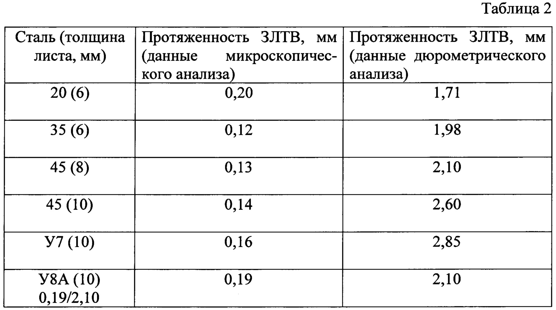
Данные дюрометрического анализа свидетельствуют, что протяженность области, имеющей повышенную по сравнению с исходным состоянием микротвердость, на порядок больше, чем при микроскопическом анализе.Durometric analysis data indicate that the length of the region, which has an increased microhardness compared to the initial state, is an order of magnitude greater than with microscopic analysis.
Такая разница протяженности ЗЛТВ, по данным разных методов, обусловлена особенностями самих методом исследования. Микроанализ способен зафиксировать только области с измененной микроструктурой, т.е. те, которые при лазерной резке нагревались выше Ac1 и в которых при ускоренном охлаждении происходили фазовые превращения. Однако в областях стали, нагретых ниже Ас1, развиваются рекристаллизационные процессы и процессы старения (термического и деформационного). Ac1 - это температура первого фазового превращения перлита в аустенит при нагревании углеродистых доэвтектоидных и эвтектоидных сталей.Such a difference in the length of the HLTV, according to different methods, is due to the characteristics of the research method itself. Microanalysis is able to capture only areas with a modified microstructure, i.e. those that were heated above A c1 during laser cutting and in which phase transformations occurred during accelerated cooling. However, in areas of steel heated below A s1 , recrystallization processes and aging processes (thermal and deformation) develop. A c1 is the temperature of the first phase transformation of perlite into austenite when heated carbonaceous hypereutectoid and eutectoid steels.
Дюрометрический анализ отражает влияние на микротвердость всего спектра процессов фазовых и структурных изменений в приповерхностной области, развивающихся при лазерной резке при ускоренном нагреве и охлаждении (L). При дальнейшем рассмотрении запротяженность ЗЛТВ принимали данные, полученные дюрометрическим анализом.Durometric analysis reflects the effect on the microhardness of the entire spectrum of processes of phase and structural changes in the surface region that develop during laser cutting with accelerated heating and cooling (L). Upon further consideration, the extent of the ZLTV took data obtained by durometric analysis.
В результате исследований была выявлена взаимосвязь протяженности (глубины) ЗЛТВ с параметрами лазерной резки (Н, W, v, Р и F) и содержанием углерода, которая нашла свое отражение в следующей зависимости:As a result of the studies, the relationship between the length (depth) of the HLTE with the parameters of laser cutting (H, W, v, P and F) and the carbon content was revealed, which was reflected in the following relationship:
L=-1,30-0,0042(Н×W0,5)+0,0049(F1,25С0,2)-0,95(Р0,2×v0,01), мм,L = -1.30-0.0042 (N × W 0.5 ) +0.0049 (F 1.25 C 0.2 ) -0.95 (P 0.2 × v 0.01 ), mm
где С - содержание углерода в детали, %; Н - толщина листа, мм; W - мощность лазерного излучения, кВт; v - скорость лазерной резки, м/мин; Р - давление технологического газа, кПа; F - положение фокального пятна (фокусное расстояние) мм; -1,30; 0,0042; 0,0049 и 0,95 - математические константы.where C is the carbon content in the part,%; N - sheet thickness, mm; W is the laser radiation power, kW; v is the speed of laser cutting, m / min; P is the pressure of the process gas, kPa; F is the position of the focal spot (focal length) mm; -1.30; 0.0042; 0.0049 and 0.95 are mathematical constants.
Полученная зависимость характеризует протяженность зоны лазерного термического влияния (упрочненного приповерхностного слоя) в зависимости от толщины листа, мощности лазерного излучения, скорости лазерной резки, давления технологического газа, положения фокального пятна в указанных интервалах изменения параметров лазерной резки при изменении толщины разрезаемого листа от 6 до 10 мм.The obtained dependence characterizes the extent of the laser thermal influence zone (hardened surface layer) depending on the sheet thickness, laser radiation power, laser cutting speed, process gas pressure, focal spot position in the indicated intervals of the laser cutting parameters when the thickness of the cut sheet varies from 6 to 10 mm
Управляя глубиной упрочненного поверхностного слоя в процессе лазерной резки в соответствии с указанной выше зависимостью, целесообразно выбирать параметры лазерной резки из следующего диапазона: W=0,8-1,4 кВт; v=0,7-1,2 м/мин; Р=15-50 кПа; F=295-305 мм.By controlling the depth of the hardened surface layer during laser cutting in accordance with the above dependence, it is advisable to choose the parameters of laser cutting from the following range: W = 0.8-1.4 kW; v = 0.7-1.2 m / min; P = 15-50 kPa; F = 295-305 mm.
Claims (9)
Priority Applications (1)
| Application Number | Priority Date | Filing Date | Title |
|---|---|---|---|
| RU2018140047A RU2695715C1 (en) | 2018-11-14 | 2018-11-14 | Method of forming hardened near-surface layer in laser cutting area of parts |
Applications Claiming Priority (1)
| Application Number | Priority Date | Filing Date | Title |
|---|---|---|---|
| RU2018140047A RU2695715C1 (en) | 2018-11-14 | 2018-11-14 | Method of forming hardened near-surface layer in laser cutting area of parts |
Publications (1)
| Publication Number | Publication Date |
|---|---|
| RU2695715C1 true RU2695715C1 (en) | 2019-07-25 |
Family
ID=67512278
Family Applications (1)
| Application Number | Title | Priority Date | Filing Date |
|---|---|---|---|
| RU2018140047A RU2695715C1 (en) | 2018-11-14 | 2018-11-14 | Method of forming hardened near-surface layer in laser cutting area of parts |
Country Status (1)
| Country | Link |
|---|---|
| RU (1) | RU2695715C1 (en) |
Citations (5)
| Publication number | Priority date | Publication date | Assignee | Title |
|---|---|---|---|---|
| JPH0471796A (en) * | 1990-07-11 | 1992-03-06 | Mitsubishi Electric Corp | Laser cutting method |
| SU1756075A1 (en) * | 1990-03-05 | 1992-08-23 | Киевский Политехнический Институт Им.50-Летия Великой Октябрьской Социалистической Революции | Method of laser cutting |
| SU1743097A3 (en) * | 1990-09-26 | 1994-01-15 | НИИ технологии и организации производства двигателей | Laser cutting |
| JP2003117670A (en) * | 2001-10-15 | 2003-04-23 | Nippon Steel Corp | Laser cutting method for steel sheet |
| JP2007144517A (en) * | 2005-11-25 | 2007-06-14 | L'air Liquide | How to cut stainless steel with fiber laser |
-
2018
- 2018-11-14 RU RU2018140047A patent/RU2695715C1/en active
Patent Citations (5)
| Publication number | Priority date | Publication date | Assignee | Title |
|---|---|---|---|---|
| SU1756075A1 (en) * | 1990-03-05 | 1992-08-23 | Киевский Политехнический Институт Им.50-Летия Великой Октябрьской Социалистической Революции | Method of laser cutting |
| JPH0471796A (en) * | 1990-07-11 | 1992-03-06 | Mitsubishi Electric Corp | Laser cutting method |
| SU1743097A3 (en) * | 1990-09-26 | 1994-01-15 | НИИ технологии и организации производства двигателей | Laser cutting |
| JP2003117670A (en) * | 2001-10-15 | 2003-04-23 | Nippon Steel Corp | Laser cutting method for steel sheet |
| JP2007144517A (en) * | 2005-11-25 | 2007-06-14 | L'air Liquide | How to cut stainless steel with fiber laser |
Non-Patent Citations (1)
| Title |
|---|
| КОВАЛЕНКО В.С."Упрочнение деталей лучом лазера", Киев, Техника, 1981, с.37. * |
Similar Documents
| Publication | Publication Date | Title |
|---|---|---|
| So et al. | An investigation of the blanking process of the quenchable boron alloyed steel 22MnB5 before and after hot stamping process | |
| US11590609B2 (en) | Laser shock peening apparatuses and methods | |
| Lesyk et al. | Surface microrelief and hardness of laser hardened and ultrasonically peened AISI D2 tool steel | |
| Grum et al. | Effect of laser-remelting of surface cracks on microstructure and residual stresses in 12Ni maraging steel | |
| Speidel et al. | Surface modification of mild steel using a combination of laser and electrochemical processes | |
| Šebek et al. | The effects of laser surface hardening on microstructural characteristics and wear resistance of AISI H11 hot work tool steel | |
| Charee et al. | Experimental investigation and modeling of laser surface melting process for AISI 9254 commercially high silicon spring steel | |
| Colombini et al. | Laser quenching of ionic nitrided steel: effect of process parameters on microstructure and optimization | |
| Järvenpää et al. | Local laser heat treatments of steel sheets | |
| Netprasert et al. | Surface hardening of AISI 420 stainless steel by using a nanosecond pulse laser | |
| Kapustynskyi et al. | Optimization of the parameters of local laser treatment for the creation of reinforcing ribs in thin metal sheets | |
| RU2695715C1 (en) | Method of forming hardened near-surface layer in laser cutting area of parts | |
| Yazdani et al. | Effects of heat treatment on interface microstructure and mechanical properties of explosively welded Ck60/St37 plates | |
| Zaied et al. | Analysis of heat affected zone obtained by CO2 laser cutting of low carbon steel (S235) | |
| Miraoui et al. | Effect of laser beam diameter on cut edge of steel plates obtained by laser machining | |
| RU2517632C1 (en) | Increasing physical-mechanical properties of tool and structural steels by volumetric pulsed laser hardening | |
| Ulewicz et al. | Impact of Laser Machining on the Structure and Properties of Tool Steels | |
| RU2707374C1 (en) | Method for formation of a hardened surface layer in the zone of laser cutting of parts from alloyed structural steels | |
| Ravnikar et al. | Investigation of laser surface remelting supported by acoustic emission analysis and machine learning | |
| Toktaş et al. | Investigating the wear behaviour of induction hardened 100Cr6 steel | |
| RU2375465C1 (en) | Method of surface hardening | |
| Zulhishamuddin et al. | Optimization of pulsed Nd: YAG laser melting of gray cast iron at different spot sizes for enhanced surface properties | |
| RU2820138C1 (en) | Method for robotic laser hardening of articles from die steel | |
| Biryukov et al. | Effect of Laser Annealing on Parameters of Hardened Zones and Their Tribological Properties | |
| RU2777793C1 (en) | Method for laser surface treatment of steel products |