RU2684467C2 - Double-side razor - Google Patents
Double-side razor Download PDFInfo
- Publication number
- RU2684467C2 RU2684467C2 RU2016135684A RU2016135684A RU2684467C2 RU 2684467 C2 RU2684467 C2 RU 2684467C2 RU 2016135684 A RU2016135684 A RU 2016135684A RU 2016135684 A RU2016135684 A RU 2016135684A RU 2684467 C2 RU2684467 C2 RU 2684467C2
- Authority
- RU
- Russia
- Prior art keywords
- razor
- cartridge
- handle
- double
- sided
- Prior art date
Links
- 230000003020 moisturizing effect Effects 0.000 claims description 10
- 238000003466 welding Methods 0.000 claims description 6
- 238000000034 method Methods 0.000 abstract description 15
- 238000005520 cutting process Methods 0.000 abstract description 12
- 239000000126 substance Substances 0.000 abstract 1
- 239000000463 material Substances 0.000 description 20
- 229920001971 elastomer Polymers 0.000 description 10
- 239000005060 rubber Substances 0.000 description 10
- 239000004033 plastic Substances 0.000 description 9
- 229920003023 plastic Polymers 0.000 description 9
- 230000007246 mechanism Effects 0.000 description 4
- 229910000831 Steel Inorganic materials 0.000 description 3
- 230000008901 benefit Effects 0.000 description 3
- 239000010959 steel Substances 0.000 description 3
- XLYOFNOQVPJJNP-UHFFFAOYSA-N water Substances O XLYOFNOQVPJJNP-UHFFFAOYSA-N 0.000 description 3
- GVJHHUAWPYXKBD-UHFFFAOYSA-N (±)-α-Tocopherol Chemical compound OC1=C(C)C(C)=C2OC(CCCC(C)CCCC(C)CCCC(C)C)(C)CCC2=C1C GVJHHUAWPYXKBD-UHFFFAOYSA-N 0.000 description 2
- VYZAMTAEIAYCRO-UHFFFAOYSA-N Chromium Chemical compound [Cr] VYZAMTAEIAYCRO-UHFFFAOYSA-N 0.000 description 2
- 150000001875 compounds Chemical class 0.000 description 2
- 238000010276 construction Methods 0.000 description 2
- 239000002184 metal Substances 0.000 description 2
- 229910052751 metal Inorganic materials 0.000 description 2
- 235000002961 Aloe barbadensis Nutrition 0.000 description 1
- 244000186892 Aloe vera Species 0.000 description 1
- 229930003427 Vitamin E Natural products 0.000 description 1
- 229910045601 alloy Inorganic materials 0.000 description 1
- 239000000956 alloy Substances 0.000 description 1
- 235000011399 aloe vera Nutrition 0.000 description 1
- 230000009286 beneficial effect Effects 0.000 description 1
- 230000002146 bilateral effect Effects 0.000 description 1
- 210000000038 chest Anatomy 0.000 description 1
- 229910052804 chromium Inorganic materials 0.000 description 1
- 239000011651 chromium Substances 0.000 description 1
- 238000001035 drying Methods 0.000 description 1
- 238000005516 engineering process Methods 0.000 description 1
- 230000002349 favourable effect Effects 0.000 description 1
- -1 for example Substances 0.000 description 1
- WIGCFUFOHFEKBI-UHFFFAOYSA-N gamma-tocopherol Natural products CC(C)CCCC(C)CCCC(C)CCCC1CCC2C(C)C(O)C(C)C(C)C2O1 WIGCFUFOHFEKBI-UHFFFAOYSA-N 0.000 description 1
- 238000005304 joining Methods 0.000 description 1
- 239000006210 lotion Substances 0.000 description 1
- 210000002445 nipple Anatomy 0.000 description 1
- 230000000284 resting effect Effects 0.000 description 1
- 238000007789 sealing Methods 0.000 description 1
- 230000006641 stabilisation Effects 0.000 description 1
- 238000011105 stabilization Methods 0.000 description 1
- 230000000087 stabilizing effect Effects 0.000 description 1
- 239000010935 stainless steel Substances 0.000 description 1
- 229910001220 stainless steel Inorganic materials 0.000 description 1
- 238000003860 storage Methods 0.000 description 1
- 230000007704 transition Effects 0.000 description 1
- 229940046009 vitamin E Drugs 0.000 description 1
- 235000019165 vitamin E Nutrition 0.000 description 1
- 239000011709 vitamin E Substances 0.000 description 1
Images


Classifications
-
- B—PERFORMING OPERATIONS; TRANSPORTING
- B26—HAND CUTTING TOOLS; CUTTING; SEVERING
- B26B—HAND-HELD CUTTING TOOLS NOT OTHERWISE PROVIDED FOR
- B26B21/00—Razors of the open or knife type; Safety razors or other shaving implements of the planing type; Hair-trimming devices involving a razor-blade; Equipment therefor
- B26B21/08—Razors of the open or knife type; Safety razors or other shaving implements of the planing type; Hair-trimming devices involving a razor-blade; Equipment therefor involving changeable blades
- B26B21/14—Safety razors with one or more blades arranged transversely to the handle
- B26B21/22—Safety razors with one or more blades arranged transversely to the handle involving several blades to be used simultaneously
- B26B21/222—Safety razors with one or more blades arranged transversely to the handle involving several blades to be used simultaneously with the blades moulded into, or attached to, a changeable unit
- B26B21/225—Safety razors with one or more blades arranged transversely to the handle involving several blades to be used simultaneously with the blades moulded into, or attached to, a changeable unit the changeable unit being resiliently mounted on the handle
-
- B—PERFORMING OPERATIONS; TRANSPORTING
- B26—HAND CUTTING TOOLS; CUTTING; SEVERING
- B26B—HAND-HELD CUTTING TOOLS NOT OTHERWISE PROVIDED FOR
- B26B19/00—Clippers or shavers operating with a plurality of cutting edges, e.g. hair clippers, dry shavers
- B26B19/38—Details of, or accessories for, hair clippers, or dry shavers, e.g. housings, casings, grips, guards
- B26B19/40—Lubricating
-
- B—PERFORMING OPERATIONS; TRANSPORTING
- B26—HAND CUTTING TOOLS; CUTTING; SEVERING
- B26B—HAND-HELD CUTTING TOOLS NOT OTHERWISE PROVIDED FOR
- B26B21/00—Razors of the open or knife type; Safety razors or other shaving implements of the planing type; Hair-trimming devices involving a razor-blade; Equipment therefor
- B26B21/08—Razors of the open or knife type; Safety razors or other shaving implements of the planing type; Hair-trimming devices involving a razor-blade; Equipment therefor involving changeable blades
- B26B21/14—Safety razors with one or more blades arranged transversely to the handle
- B26B21/22—Safety razors with one or more blades arranged transversely to the handle involving several blades to be used simultaneously
- B26B21/222—Safety razors with one or more blades arranged transversely to the handle involving several blades to be used simultaneously with the blades moulded into, or attached to, a changeable unit
-
- B—PERFORMING OPERATIONS; TRANSPORTING
- B26—HAND CUTTING TOOLS; CUTTING; SEVERING
- B26B—HAND-HELD CUTTING TOOLS NOT OTHERWISE PROVIDED FOR
- B26B21/00—Razors of the open or knife type; Safety razors or other shaving implements of the planing type; Hair-trimming devices involving a razor-blade; Equipment therefor
- B26B21/40—Details or accessories
- B26B21/4012—Housing details, e.g. for cartridges
-
- B—PERFORMING OPERATIONS; TRANSPORTING
- B26—HAND CUTTING TOOLS; CUTTING; SEVERING
- B26B—HAND-HELD CUTTING TOOLS NOT OTHERWISE PROVIDED FOR
- B26B21/00—Razors of the open or knife type; Safety razors or other shaving implements of the planing type; Hair-trimming devices involving a razor-blade; Equipment therefor
- B26B21/40—Details or accessories
- B26B21/4037—Details or parts covering the blades, e.g. caps for storage; Attachments
-
- B—PERFORMING OPERATIONS; TRANSPORTING
- B26—HAND CUTTING TOOLS; CUTTING; SEVERING
- B26B—HAND-HELD CUTTING TOOLS NOT OTHERWISE PROVIDED FOR
- B26B21/00—Razors of the open or knife type; Safety razors or other shaving implements of the planing type; Hair-trimming devices involving a razor-blade; Equipment therefor
- B26B21/40—Details or accessories
- B26B21/44—Means integral with, or attached to, the razor for storing shaving-cream, styptic, or the like
- B26B21/443—Lubricating strips attached to the razor head
-
- B—PERFORMING OPERATIONS; TRANSPORTING
- B26—HAND CUTTING TOOLS; CUTTING; SEVERING
- B26B—HAND-HELD CUTTING TOOLS NOT OTHERWISE PROVIDED FOR
- B26B21/00—Razors of the open or knife type; Safety razors or other shaving implements of the planing type; Hair-trimming devices involving a razor-blade; Equipment therefor
- B26B21/40—Details or accessories
- B26B21/52—Handles, e.g. tiltable, flexible
- B26B21/521—Connection details, e.g. connection to razor heads
Landscapes
- Life Sciences & Earth Sciences (AREA)
- Forests & Forestry (AREA)
- Engineering & Computer Science (AREA)
- Mechanical Engineering (AREA)
- Packaging Of Annular Or Rod-Shaped Articles, Wearing Apparel, Cassettes, Or The Like (AREA)
- Dry Shavers And Clippers (AREA)
- Knives (AREA)
- Percussion Or Vibration Massage (AREA)
Abstract
Description
[0001] Настоящая заявка испрашивает приоритет предварительной заявки на патент США №61/948,203, поданной 5 марта 2014 года, полное содержание которой включается в настоящий документ посредством ссылки.[0001] This application claims the priority of provisional patent application US No. 61/948,203, filed March 5, 2014, the full contents of which are incorporated herein by reference.
ОБЛАСТЬ ТЕХНИКИFIELD OF TECHNOLOGY
[0002] Настоящее изобретение в целом относится к бритвенным системам, в частности к сменному, двустороннему блоку лезвий для бритвенной системы.[0002] The present invention relates generally to shaving systems, in particular to a replaceable, double-sided blade unit for a shaving system.
ПРЕДПОСЫЛКИ СОЗДАНИЯ ИЗОБРЕТЕНИЯBACKGROUND OF THE INVENTION
[0003] Обычные бритвы имеют одно-пять лезвий лишь с одной стороны, и когда они затупляются, мы их выбрасываем. Типичный потребитель покупает либо одноразовые бритвы, либо бритвы со сменный картриджем. Одноразовые бритвы менее дорогостоящие, а бритвы со сменным картриджем стоят существенно дороже. Одна из проблем состоит в том, что потребители вынуждены платить высокую цену за бритвы с картриджами и еще более высокие цены на продаваемые отдельно сменные картриджи.[0003] Ordinary razors have one to five blades on only one side, and when they become dull, we throw them away. A typical consumer buys either disposable razors or razors with a replaceable cartridge. Disposable razors are less expensive, and razors with a replaceable cartridge are significantly more expensive. One problem is that consumers are forced to pay a high price for cartridge razors and even higher prices for separately sold replacement cartridges.
КРАТКОЕ ОПИСАНИЕSHORT DESCRIPTION
[0004] Поскольку многие потребители не хотят платить высокие цены за бритвы, но при этом не имеют никакого выбора, двусторонняя бритва позволяет потребителям использовать ее в течение более длительного времени, благодаря картриджу бритвы, у которой потребитель может использовать обе стороны картриджа. Это позволяет сэкономить деньги потребителей, поскольку им не нужно покупать большое количество сменных картриджей бритвы в течение года, так как срок службы бритвы может быть увеличен в два раза. Двусторонняя бритва предоставляет потребителям приемлемый выбор. Данное изобретение дает потребителям еще один выбор в вопросе средств бритья, предлагая им двойную выгоду в вопросе бритья, при этом сохраняя качество и деньги потребителей.[0004] Since many consumers do not want to pay high prices for razors, but have no choice, a double-sided razor allows consumers to use it for a longer time, thanks to the razor cartridge, in which the consumer can use both sides of the cartridge. This saves consumers money, since they do not need to buy a large number of replaceable razor cartridges during the year, since the life of the razor can be doubled. The double-sided razor provides consumers with an acceptable choice. This invention gives consumers one more choice in the matter of shaving, offering them double benefits in the matter of shaving, while maintaining the quality and money of consumers.
[0005] В двусторонней бритве имеется от одного до пяти лезвий в двустороннем картридже и острый край для бритья на каждом конце лезвия. Таким образом, потребитель может использовать одну сторону бритвы до тех пор, пока она не затупится, а затем использовать другую сторону картриджа бритвы, в результате чего срок службы бритвенного станка увеличивается в два раза. Бритва использует оба конца лезвия бритвы, что позволяет избежать неиспользования другого конца лезвия, который не используется или не предназначен для бритья. После этого пользователь отсоединяет двусторонний картридж бритвы от крепежа для закрепления ручки, поворачивает на 180 градусов или переворачивает картридж бритвы и прикрепляет его к другой стороне бритвы с двусторонним картриджем. Потребитель может использовать такую вторую сторону картриджа бритвы до тех пор, пока она не затупится. Когда картридж бритвы затупится, пользователь должен снять двусторонний картридж и присоединить новый двусторонний картридж к ручке бритвы. Это позволяет увеличить потребителю срок эксплуатации бритвы в два раза за счет использования обоих концов лезвия бритвы.[0005] A double-sided razor has one to five blades in a double-sided cartridge and a sharp shaving edge at each end of the blade. Thus, the consumer can use one side of the razor until it is dull, and then use the other side of the razor cartridge, resulting in a doubled service life of the razor. The razor uses both ends of the razor blade, avoiding the non-use of the other end of the blade that is not used or not intended for shaving. After that, the user disconnects the double-sided razor cartridge from the fastener to fix the handle, rotates 180 degrees or turns the razor cartridge and attaches it to the other side of the razor with a double-sided cartridge. A consumer may use such a second side of the razor cartridge until it becomes dull. When the razor cartridge is dull, the user must remove the duplex cartridge and attach a new duplex cartridge to the razor handle. This allows the consumer to double the life of the razor by using both ends of the razor blade.
[0006] Пользователь может купить бритву, идущую в комплекте с двусторонними картриджами. Или пользователь может купить сменные картриджи и заменить существующие двусторонние картриджи бритвы.[0006] A user can buy a shaver included with double-sided cartridges. Or the user can buy replacement cartridges and replace existing double-sided razor cartridges.
[0007] Для подсоединения или отсоединения бритвы к и от двустороннего картриджа, пользователь должен взяться за ручку одной рукой и держать концы двустороннего картриджа (конец и стороны, на которых нет лезвий) другой рукой. Затем пользователь должен поставить области соединения закрепления ручки, расположенные на ручке, в отсек крепления на лицевой стороне картриджа, в отсеки соединения лицевой стороны картриджа или прорези до полного соединения, установки внутрь, и, предпочтительно, фиксации в области отсека картриджа.[0007] To connect or disconnect the shaver to and from the double-sided cartridge, the user must hold the handle with one hand and hold the ends of the double-sided cartridge (end and sides that do not have blades) with the other hand. The user then has to place the handle fastening connection areas located on the handle into the fastening compartment on the front side of the cartridge, into the connection compartments of the front side of the cartridge or slots until they are fully connected, installed inward, and preferably locked in the area of the cartridge compartment.
[0008] В одном варианте осуществления легкое соединение происходит, если ручка бритвы и соединение закрепления ручки при вставке (соединении или отсоединении) перпендикулярны отсеку крепления на лицевой стороне картриджа. Может использоваться множество способов вставки (соединения или отсоединения) соединения закрепления ручки (ручки бритвы) и двустороннего картриджа, известных в настоящее время или разработанных в будущем. Несмотря на то, что некоторые варианты осуществления описываются в данном документе, следует понимать, что предусмотрены также другие варианты осуществления.[0008] In one embodiment, an easy connection occurs if the razor handle and the handle fastening connection when inserting (connecting or disconnecting) are perpendicular to the attachment compartment on the front of the cartridge. Many methods can be used to insert (attach or detach) the attachment of the grip handle (razor handle) and the double-sided cartridge, currently known or developed in the future. Although some embodiments are described herein, it should be understood that other embodiments are also provided.
[0009] Настоящее раскрытие изобретения позволяет потребителям сэкономить деньги за счет обеспечивая увеличенного в два раза срока эксплуатации обычных бритв и картриджей. Таким образом, потребители могут тратить меньше денег в год на бритвы. Данная концепция весьма полезна и крайне необходима на рынке. В отличие от предыдущих концепций двусторонней бритвы, бритва настоящих вариантов осуществления, описанных в данном документе, имеет новый и усовершенствованный способ предложения потребителям двусторонней бритвы с лучшими характеристиками бритья, увеличенным в два раза сроком эксплуатации, что в свою очередь экономит деньги потребителей.[0009] The present disclosure of the invention allows consumers to save money by providing twice the life of conventional razors and cartridges. Thus, consumers can spend less money a year on razors. This concept is very useful and extremely necessary in the market. Unlike previous double-sided razor concepts, the razor of the present embodiments described herein has a new and improved way to offer consumers a double-sided razor with better shaving characteristics, twice the life of the shaver, which in turn saves consumers money.
Есть много уникальных аспектов раскрытия настоящего изобретения, упрощающие потребителю способ использования картриджа бритвы, который может применяться для бритья с обеих сторон.There are many unique aspects of the disclosure of the present invention that make it easier for the consumer to use a razor cartridge that can be used to shave on both sides.
[0010] Двусторонняя бритва, выполненная в виде двусторонней одноразовой бритвы, может обладать всеми техническими характеристиками и сменными элементами, упомянутыми в настоящей заявке. Двусторонняя одноразовая бритва может быть любой формы, дизайна и размера и быть изготовлена из любого материала, известного в настоящее время или разработанного в будущем. Одно из не ограничивающих различий между двусторонней одноразовой бритвой и двусторонней многоразовой бритвой заключается в том, что лезвия и картриджи одноразовой бритвы могут быть выполнены из менее дорогих материалов и предназначены для использования лишь ограниченное количество раз, после чего их нужно просто выбросить.[0010] A double-sided razor made in the form of a double-sided disposable razor may have all the technical characteristics and interchangeable elements mentioned in this application. A double-sided disposable razor can be of any shape, design and size and can be made of any material currently known or developed in the future. One non-limiting difference between a double-sided disposable razor and a double-sided reusable razor is that the blades and cartridges of a disposable razor can be made from less expensive materials and are designed to be used only a limited number of times, after which they simply need to be thrown away.
КРАТКОЕ ОПИСАНИЕ ЧЕРТЕЖЕЙBRIEF DESCRIPTION OF THE DRAWINGS
[0011] ФИГ. 1 - вид в перспективе одного варианта осуществления бритвенной системы, содержащей один вариант осуществления картриджа по настоящему изобретению, соединенного с вариантом осуществления ручки по настоящему изобретению;FIG. 1 is a perspective view of one embodiment of a shaving system comprising one embodiment of a cartridge of the present invention coupled to an embodiment of a handle of the present invention;
[0012] ФИГ. 2 - изображение в разобранном виде и ФИГ. 3 - изображение в частично собранном виде одного из вариантов осуществления картриджа;FIG. 2 is an exploded view and FIG. 3 is a partially assembled image of one embodiment of a cartridge;
[0013] ФИГ. 4-5 - перспективные виды сзади варианта осуществления ручки в зацепление с картриджем, при этом на ФИГ. 4 показано положение зацепления/выпуска, а на ФИГ. 5 показано положение использования с картриджем, повернутым в сторону от положения зацепления/выпуска;FIG. 4-5 are perspective rear views of an embodiment of a handle engaged with a cartridge, with FIG. 4 shows the position of the engagement / release, and FIG. 5 shows the usage position with the cartridge rotated away from the engagement / release position;
[0014] ФИГ. 6 - перспективный вид спереди одного варианта осуществления ручки без картриджа;FIG. 6 is a perspective front view of one embodiment of a handle without a cartridge;
[0015] ФИГ. 7 - перспективный вид спереди одного варианта осуществления картриджа, соединенного с. ручкой, изображенной на ФИГ. 6;FIG. 7 is a perspective front view of one embodiment of a cartridge connected to. the pen shown in FIG. 6;
[0016] ФИГ. 8 - перспективный вид сзади одного варианта осуществления ручки, содержащей логотип;FIG. 8 is a perspective rear view of one embodiment of a pen containing a logo;
[0017] ФИГ. 9 - перспективный вид сзади одного варианта осуществления картриджа, соединенного с ручкой, изображенной на ФИГ. 8;FIG. 9 is a perspective rear view of one embodiment of a cartridge connected to a pen of FIG. 8;
[0018] ФИГ. 10 - перспективный вид спереди одного варианта осуществления ручки, содержащей один вариант осуществления закрепления ручки;FIG. 10 is a perspective front view of one embodiment of a handle containing one embodiment of a handle;
[0019] ФИГ. 11 - перспективный вид сзади ручки, изображенной на ФИГ. 10;FIG. 11 is a perspective rear view of the handle shown in FIG. 10;
[0020] ФИГ. 12 - схематический вид одного из вариантов осуществления шарнирного соединения;FIG. 12 is a schematic view of one embodiment of a swivel;
[0021] ФИГ. 13 - схематический вид одного из вариантов осуществления Т-образного соединения;FIG. 13 is a schematic view of one embodiment of a T-joint;
[0022] ФИГ. 14 - схематический вид одного из вариантов осуществления половины Т- или Г-образного соединения;FIG. 14 is a schematic view of one embodiment of half a T- or L-shaped joint;
[0023] ФИГ. 15 - схематический вид одного из вариантов осуществления половины "Т" или "Г"-образного соединения;FIG. 15 is a schematic view of one embodiment of a half “T” or “G” -shaped connection;
[0024] ФИГ. 16 - схематический вид одного из вариантов осуществления соединения продолговатого или длинного стержня;FIG. 16 is a schematic view of one embodiment of an elongated or long rod joint;
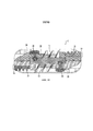
[0025] ФИГ. 17 - схематический вид одного из вариантов осуществления соединения продолговатого или длинного стержня;FIG. 17 is a schematic view of one embodiment of an elongated or long rod joint;
[0026] ФИГ. 18 - вид спереди одного из вариантов осуществления ручки по настоящему изобретению;FIG. 18 is a front view of one embodiment of a pen of the present invention;
[0027] ФИГ. 19 - частично разобранный вид ручки, изображенной на ФИГ. 18, представляющей один из вариантов осуществления соединения с пружинным штифтом;FIG. 19 is a partially exploded view of the handle shown in FIG. 18, representing one embodiment of a spring pin connection;
[0028] ФИГ. 20 - перспективный вид одного из вариантов осуществления картриджа по настоящему изобретению;FIG. 20 is a perspective view of one embodiment of a cartridge of the present invention;
[0029] ФИГ. 21 - перспективный вид одного из вариантов осуществления картриджа, изображенного на ФИГ. 20, который соединен с вариантом осуществления ручки по настоящему изобретению;FIG. 21 is a perspective view of one embodiment of the cartridge of FIG. 20, which is connected to an embodiment of the handle of the present invention;
[0030] ФИГ. 22 - поперечное сечение, выполненное по линии 22-22 на ФИГ. 21;FIG. 22 is a cross section taken along line 22-22 of FIG. 21;
[0031] ФИГ. 23 - перспективный вид одного из вариантов осуществления картриджа;FIG. 23 is a perspective view of one embodiment of a cartridge;
[0032] ФИГ. 24 - вид спереди одного из вариантов осуществления картриджа;FIG. 24 is a front view of one embodiment of a cartridge;
[0033] ФИГ. 25 - вид в поперечном сечении, выполненный по линии 25-25 на ФИГ. 24;FIG. 25 is a cross-sectional view taken along line 25-25 of FIG. 24;
[0034] ФИГ. 26 - вид сзади одного из вариантов осуществления картриджа с крышкой;FIG. 26 is a rear view of one embodiment of a cartridge with a cap;
[0035] ФИГ. 27 - вид в перспективе сверху одного из вариантов осуществления закрытого картридж;FIG. 27 is a top perspective view of one embodiment of a closed cartridge;
[0036] ФИГ. 28 - вид сзади одного из вариантов осуществления картриджа, соединенного с ручкой;FIG. 28 is a rear view of one embodiment of a cartridge connected to a handle;
[0037] ФИГ. 29 - вид сверху в перспективе одного из вариантов осуществления картриджа с крышкой, прикрепленной к противоположной лицевой стороне;FIG. 29 is a top perspective view of one embodiment of a cartridge with a cap attached to the opposite front side;
[0038] ФИГ. 30 - вид сбоку картриджа, изображенного на ФИГ. 29;FIG. 30 is a side view of the cartridge shown in FIG. 29;
[0039] ФИГ. 31 - вид в разобранном состоянии одного из вариантов осуществления картриджа по настоящему изобретению;FIG. 31 is an exploded view of one embodiment of a cartridge of the present invention;
[0040] ФИГ. 32 - вид сверху на кромку одного из вариантов осуществления картриджа по настоящему изобретению;FIG. 32 is a top view of the edge of one embodiment of the cartridge of the present invention;
[0041] ФИГ. 33 - вид слева вертикальной проекции изобретения;FIG. 33 is a left side elevational view of the invention;
[0042] ФИГ. 34 - вид изобретения спереди;FIG. 34 is a front view of the invention;
[0043] ФИГ. 35 - вид справа вертикальной проекции изобретения;FIG. 35 is a right side elevational view of the invention;
[0044] ФИГ. 36 - вид снизу кромки по настоящему изобретению;FIG. 36 is a bottom view of an edge of the present invention;
[0045] ФИГ. 37 - вид сверху в перспективе по настоящему изобретению;FIG. 37 is a top perspective view of the present invention;
[0046] ФИГ. 38 - крупный план закругленной части 38, изображенной на ФИГ. 34;FIG. 38 is a close-up of the rounded
[0047] ФИГ. 39 - поперечное сечение, выполненное по линии 39-39 на ФИГ. 34;FIG. 39 is a cross section taken along line 39-39 of FIG. 34;
[0048] ФИГ. 40 - вид сверху одного из вариантов осуществления ручки в соответствии с настоящим изобретением;FIG. 40 is a top view of one embodiment of a pen in accordance with the present invention;
[0049] ФИГ. 41 - вид сбоку по настоящему изобретению;FIG. 41 is a side view of the present invention;
[0050] ФИГ. 42 вид снизу в разобранном виде по настоящему изобретению; иFIG. 42 is an exploded bottom view of the present invention; and
[0051] ФИГ. 43 - схематический вид одного из вариантов осуществления набора включающего ручку и множество картриджей.FIG. 43 is a schematic view of one embodiment of a kit including a pen and a plurality of cartridges.
ПОДРОБНОЕ ОПИСАНИЕ ПРЕДПОЧТИТЕЛЬНЫХ ВАРИАНТОВ ОСУЩЕСТВЛЕНИЯDETAILED DESCRIPTION OF THE PREFERRED EMBODIMENTS
[0052] Описание иллюстративных вариантов осуществления в соответствии с принципами настоящего изобретения предназначено для чтения совместно с прилагаемыми чертежами, которые следует рассматривать как часть письменного описания в целом. В описании вариантов осуществления настоящего изобретения, раскрытого здесь, любая ссылка на направление или ориентацию предназначена лишь для удобства описания и не предназначена никоим образом ограничивать область применения настоящего изобретения. Относительные величины, такие как "нижний", "верхний", "горизонтальный", "вертикальный", "выше", "ниже", "вверх", "вниз", "сверху" и "снизу", а также их производные (например, "в горизонтальном направлении", "в направлении вниз", "в направлении вверх" и т.д.) следует истолковывать со ссылкой на ориентацию, описанную или изображенную на обсуждаемом чертеже. Такие относительные величины даны лишь для удобства описания и не требуют, чтобы устройство было сконструировано или работало в определенной ориентации, если она явно не указано, как таковая. Такие понятия, как "прикрепленной", "закрепленный", "соединенный", "связанный", "взаимосвязанный" и подобные, относятся к связи, при которой конструкции скреплены или соединены между собой, прямо или косвенно, посредством промежуточных конструкций, а также как подвижными или жесткими крепежными элементами или связями, если не указано иное. Кроме того, признаки и преимущества изобретения проиллюстрированы посредством ссылки на варианты осуществления, приведенные в качестве примеров. Соответственно, настоящее изобретение не должно явно ограничиваться такими примерными вариантами осуществления, иллюстрирующими некоторые возможные неограничивающие комбинации признаков, которые могут существовать по отдельности или в других комбинациях признаков; область применения изобретения определяется согласно прилагаемой формуле изобретения.[0052] The description of illustrative embodiments in accordance with the principles of the present invention is intended to be read in conjunction with the accompanying drawings, which should be considered as part of the written description as a whole. In the description of the embodiments of the present invention disclosed herein, any reference to a direction or orientation is intended only for convenience of description and is not intended in any way to limit the scope of the present invention. Relative values, such as "lower", "upper", "horizontal", "vertical", "above", "below", "up", "down", "top" and "bottom", as well as their derivatives ( for example, “in the horizontal direction,” “in the down direction,” “in the up direction, etc.) should be construed with reference to the orientation described or depicted in the figure under discussion. Such relative values are given for convenience of description only and do not require that the device be designed or operate in a specific orientation unless explicitly indicated as such. Such concepts as “attached”, “fixed”, “connected”, “connected”, “interconnected” and the like, refer to a connection in which structures are fastened or interconnected, directly or indirectly, by means of intermediate structures, as well as movable or rigid fasteners or ties, unless otherwise indicated. In addition, the features and advantages of the invention are illustrated by reference to the exemplary embodiments. Accordingly, the present invention should not be explicitly limited to such exemplary embodiments illustrating some possible non-limiting combinations of features that may exist individually or in other combinations of features; the scope of the invention is determined according to the attached claims.
[0053] В этом документе описывается наилучший способ или способы практического осуществления изобретения, предполагаемые в настоящее время. Настоящее описание не претендует на то, чтобы быть понятым в ограничивающем смысле, но при этом приводит пример осуществления изобретения, представленный исключительно в целях иллюстрации со ссылкой на прилагаемые чертежи, которые представляют собой помощь любому обычному специалисту в данной области технике в вопросах преимущества и конструкции изобретения. При различных вариантах рассмотрения чертежей аналогичные номера позиции обозначают одинаковые или аналогичные детали.[0053] This document describes the best method or methods for practicing the invention that are currently contemplated. The present description is not intended to be understood in a limiting sense, but it provides an example embodiment of the invention, presented solely for purposes of illustration with reference to the accompanying drawings, which are of assistance to any ordinary person skilled in the art in matters of advantage and construction of the invention . In various embodiments of the consideration of the drawings, like reference numerals indicate the same or similar details.
[0054] Как видно из Фигуры 1, один вариант осуществления картриджа 2 бритвы по настоящему изобретению имеет верхний концевой участок 4, который расположен дальше всего от ручки 6. Верхний концевой участок может быть выполнен в форме овала, закруглен или иметь любую другую форму. Если он закруглен, то лицевая поверхность 8 картриджа может иметь закругленные прокладки, полоски или увлажняющие подушечки или другие вложения или функции по Вашему усмотрению. Нижняя секция (концевые участки) 10 или любые секции бритвы могут быть выполнены в любой форме, известной в настоящее время или разработанной в будущем. Концы или края 12 картриджа могут быть выполнены из резины или любого другого материала, известного в настоящее время или разработанного в будущем, который обеспечит пользователю сцепление с концами 12 картриджа, будь то в воде или без воды. Края могут быть оконтуренными, ребристыми, вогнутыми, выпуклыми или сочетать в себе сразу несколько данных характеристик. Это также помогает пользователю схватить и соединить или отсоединить картридж 2 от ручки 6, и переместить (повернуть) картридж 2 по оси, проходящей вдоль центральной продольной оси картриджа, чтобы использовать другую сторону бритвы, как это показано на Фигуре 1. При обращении с двусторонней бритвой, предпочтительно, чтобы пользователь удерживал концы или края 12 картриджа, а не само лезвии 14 или лицевую поверхность 8 картриджа. Пользователь может порезаться, если он ухватиться за лезвие 14 или лицевую поверхность 8 картриджа. На концах 12 картриджа могут располагаться подпальцевые выемки 16, которые представляют собой вогнутые и/или выпуклые области для размещения пальцев пользователя, созданные для удобства соприкосновения и легкого и надежного сцепления с картриджем 2. Лицевая поверхность 8 картриджа также предпочтительно содержит отсек крепления 20 картриджа, в который легко вставляются соединения закрепления 22 ручки. Соединение закрепления 22 ручки проходит на расстоянии от фланца 24 (места расположения рычагов или крыла). Возможно наличие закругленных прокладок, полос или увлажняющих подушечек, которые соответствуют форме верхнего, нижнего края или боковым сторонам картриджа.[0054] As can be seen from Figure 1, one embodiment of the
[0055] Картридж 2 может быть выполнен из любого типа материала, например, пластмассы, резины, металла и т.п.или их комбинации. В любом месте на картридже 2 может присутствовать любой тип материала, например резина. Картридж 2 может быть изготовлен из любого количества частей. Картридж 2 может быть соединен винтами, методом посадки с защелкиванием, тепловой сваркой, ультразвуковой сваркой, методом фиксирования или любым другим способом, известным в настоящее время или разработанным в будущем. Картридж 2 может быть любого размера и формы. В одном варианте осуществления он может быть выполнен и иметь форму бритв с прямым краем или бритв картриджного типа. В картридже 2 может быть любое количество лезвий 14, прочно или шарнирно скрепленных, например, одно лезвие, два лезвия, три лезвия, пять лезвий. Лезвия 14 могут располагаться под любой градусом угла относительно поверхности бритья, однако, предпочтительно, чтобы лезвия, были расположены в направлении шестидесяти градусов относительно поверхности бритья, хотя возможны и другие углы.[0055] The
[0056] При одном варианте осуществления половинки или части картриджа могут прочно защелкиваться воедино или быть съемными. Вы можете прикрепить их любым известным в настоящее время или разработанным в будущем способом. Предпочтительно, чтобы части картриджа образовывали надежное крепление. После того, как обе половинки картриджа соединены вместе, картридж 2 может быть подвержены термической или ультразвуковой сварке, для образования надежного крепления, не позволяющего ему сломаться, что делает его более безопасным. Ультразвуковая сварка или термосварка гарантирует стопорную посадку или любой тип соединения, который будет удержать части картриджа и бритвы в целостности, поэтому они никогда не развалятся, что делает их весьма безопасными. Части картриджа могут удерживаться вместе металлической или стальной лентой, которая соединяет два конца вместе. Возможны и другие средства закрепления. Ленты позволяют надежно соединить вместе две части картриджа. Существует много способов соединения или надежного закрепления частей картриджа, которые известны в настоящее время или будут разработаны в будущем.[0056] In one embodiment, the halves or portions of the cartridge can firmly snap together or be removable. You can attach them in any way that is currently known or developed in the future. Preferably, the cartridge parts form a secure fit. After both halves of the cartridge are connected together, the
[0057] Лицевая поверхность 8 картриджа или боковая поверхность бритья могут быть выполнены в виде двух различных частей или одной целой части. В одном варианте осуществления цельная конструкция верхняя сторона, в которой расположены прокладки и увлажняющие подушечки, может выглядеть аналогичным образом. Другая сторона (внутренняя поверхность или внутреннее пространство) в одном варианте осуществления изобретения может быть выполнена таким образом, что она выглядит так же в месте, где прикрепляются лезвия 14.[0057] The front surface of the
[0058] Как можно видеть в варианте осуществления на Фигурах 2 и 3, в устройстве предусмотрены пазы 18, в которые вставляются лезвия 14 под прямым углом, для расположения лезвий на поверхности бритья под прямым углом. Такой угол подойдет для одной стороны картриджа 2 на поверхности бритья (сторона один). Другой конец паза 18 лезвия, в который вставляются лезвия 14, подходит для другой поверхности бритья (вторая сторона) картриджа 2. Как видно на Фигурах 4 и 5, на внутренней стороне картриджа 2 имеется центральная часть 26 лезвия, которая проходит через середину каждого бритвенного лезвия 14, для целей стабилизации и удержания бритвы на месте. На Фигуре 4 показано крепление ручки к лицевой стороне картриджа лезвий, в котором картридж лезвий надлежащим образом расположен под углом для приема и зацепления с ручкой, в то время как на Фигуре 5 показан способ поворота картриджа относительно ручки в положение использования для бритья. Если необходимо снять картридж с ручки, поверните картридж из положения, показанного на Фигуре 5, в положение, показанное на Фигуре 4, после чего картридж можно будет отделить от ручки.[0058] As can be seen in the embodiment of Figures 2 and 3,
[0059] Возможно наличие соединений, при которых центральная часть 26 лезвия надежно и прочно прикреплена к поверхности картриджа, как только центральная часть 26 проходит через лезвия 14. Соединение может быть обработано термосваркой или ультразвуковой сваркой или любым другим способ, известным в настоящее время или разработанным в будущем, чтобы прикрепить и соединить его. Такая центральная часть 26 помогает лезвию 14 бритвы быть прочным, особенно в средней части лезвия бритвы 14. Необходимо стабилизировать среднюю часть лезвия 14, из-за наличия промежутка между лезвиями, поэтому центральная часть 26 лезвия помогает во время бритья удерживать лезвия 14 надежно и под прямым углом. Такая центральная часть 26 лезвия может быть изготовлена из любого материала или пластика. Лезвие 14 бритвы сконструировано и имеет такую форму, которая позволяет надежно установить его в центральной части 26 лезвия.[0059] There may be compounds in which the
[0060] Центральная часть 26 лезвия находится ближе к центру лезвию 14 бритвы, как это показано на Фигуре 2, или она может проходить через любую часть лезвия 14 бритвы, отличной от центральной. Как только центральная часть 26 лезвия проходит через центр лезвий 14, центральная часть 26 лезвия может быть прочно или шарнирно прикреплена к одной из сторон картриджа 2. Затем другая сторона картриджа может быть размещена поверх лезвий 14, центральной части 26 лезвия и другой внутренней части картриджа 2. Они могут наслаиваться друг на друга посредством методом посадки с защелкиванием или любым другим способом соединения, известным в настоящее время или разработанным в будущем. Лезвия 14, которые входят в пазы 18 для лезвий, будут выступать одним из верхних или свободных концов, а поскольку верхний картридж 2 надевается на лезвия 14 и центральную часть 26 лезвия, верхняя сторона лезвий 14 впишется в пазы 18 лезвия на внутренней части других сторон картриджа 2.[0060] The
[0061] Другая сторона картриджа 2 (внутренняя сторона) может быть выполнена таким образом, чтобы внутренняя часть идеально подходила к другим сторонам и вместе они образуют один блок, где и осуществляется соединение. Возможно наличие защелкивающих механизмов или любого другого типа соединения, известного в настоящее время или разработанного в будущем. На одной стороне могут находиться соединительные зубцы (ниппельная часть), а на другой стороне могут находиться отсеки для зубцов (промежуточные части), в которые входит зубец и надежно там закрепляется. Таким образом, каждый внутренний картридж бритвы может иметь одну сторону, в которой располагаются зубцы, и другую сторону, в которой располагаются отсеки соединения.[0061] The other side of the cartridge 2 (inner side) can be made so that the inner part fits perfectly with the other sides and together they form one block, where the connection is made. There may be snap mechanisms or any other type of connection currently known or developed in the future. On one side there may be connecting teeth (nipple part), and on the other side there may be tooth compartments (intermediate parts) into which the tooth enters and is securely fixed there. Thus, each inner razor cartridge may have one side in which the teeth are located and another side in which the connection compartments are located.
[0062] В одном варианте осуществления каждая часть или половина картриджа может быть идентична другой, и, когда эти две части картриджа или половинки соединены между собой, то пользователь должен будет повернуть картридж 2 вокруг оси таким образом, чтобы противоположные концы совпали и соединились друг с другом. Двусторонняя бритва может быть выполнена без возможности поворота картриджа вокруг оси. При установке картриджей, отсек крепления картриджа и области закрепления нажимного штифта (лицевая поверхность крепления) находятся напротив друг от друга. Внутренняя часть предпочтительно выполнена с возможностью выглядеть одинаково и наличием пазов 18 лезвия и местом для размещения лезвия. Единственное различие - зубцы и области закрепления соединения зубцов; по одному на каждом длинном конце картриджа с внутренней стороны.[0062] In one embodiment, each part or half of the cartridge may be identical to the other, and when these two parts of the cartridge or halves are connected to each other, the user will have to rotate the
[0063] В одном варианте осуществления картридж также может быть выполнен из двух различных частей или иметь любое количества частей, для достижения аналогичных целей. Картридж может быть выполнен иначе изнутри и снаружи, но по-прежнему они должны быть соединены друг с другом. Картридж может оставаться соединенным друг с другом любым известным в настоящее время или разработанным в будущем способом.[0063] In one embodiment, the cartridge may also be made of two different parts or have any number of parts to achieve similar goals. The cartridge can be made differently inside and out, but still they must be connected to each other. The cartridge may remain connected to each other by any method currently known or developed in the future.
[0064] Как можно видеть в варианте осуществления на Фигурах 6 и 7, ручка 6 имеет фиксатор на каждом конце, где ручка 6 прикрепляется к каждой стороне лицевой поверхности 8 картриджа, или в любом другом месте. Вот что делает ручку 6 двусторонней бритвы уникальной, а именно она прикрепляется и входит в зацепление с лицевой стороной картриджа. На конце ручки 6 имеется фланец 24 (рычаг или область крыла) и две области закрепления соединения 22 ручки, которые входят вовнутрь обоих концов отсеков 20 закрепления картриджа (поворотные закрепления).[0064] As can be seen in the embodiment of Figures 6 and 7, the
[0065] Фланец 24 (рычаг или область крыла) может иметь любую форму, размер или конструкцию. Два соединения закрепления 22 ручки на ручке 6 может иметь любую форму или размер и может иметь одно или любое другое число соединений закрепления 22 ручки для соединения с картриджем 2. Соединения закрепления 22 ручки могут быть любой формы, размера или конструкции, например, круглой или овальной формы, известной в настоящее время или разработанной в будущем. Ручка 6 и области соединения зацепления 22 ручки могут быть любого размера и формы и могут быть изготовлены из материала, известного в настоящее время или разработанного в будущем.[0065] Flange 24 (lever or wing area) may be of any shape, size or design. The two connections of the
[0066] Ручка 6 и/или фланец 24 (рычаг или область крыла) может иметь зажим вставки, выполненный из резины или материала для крепления в пластиковом корпусе, который вводится в пластик. Или же материалы, пластмассы или резиновый захват может быть прикреплен на передней или задней части рукоятки 6 или в любом месте на картридже 2 или на концах 12 картриджа. Ручка 6 может быть выполнена из, например, пластмассы, резины, пластичного каучука, стали, нержавеющей стали или любого материала, известного в настоящее время или разработанного в будущем. Ручка 6 может быть хромированной или выполнена из сплава с содержанием хрома. Применение других материалов также допустимо.[0066] The
[0067] Фланец 24 (рычаг или область крыла), который проходит от ручки 6, может быть наклонен, для обеспечения надлежащего угла и положения во время бритья, а также по отношению к ручке 6. Когда пользователь держит ручку 6 и бреется, бритье происходит легко, удобно, и покрывает все контуры и поверхности бритья. Фланец 24 (рычаг или область крыла) может располагаться под любым углом. Возможно наличие одного или любого количества фланцев (рычага или области крыла) 24. Соединительные концы зацепления ручки, которые присоединяются к картриджу, могут быть любой формы, продолговатые, овальные, круглые, стреловидные, квадратные, любой комбинации или любой конструкции или формы, известной в настоящее время или разработанной в будущем. Другие формы также допустимы.[0067] The flange 24 (lever or wing area) that extends from the
[0068] Как видно на Фигурах 8 и 9, ручка 6 также может содержать логотипы и брендинговые знаки 28. Логотипы или брендинговые знаки 28 могут быть выполнены из резиновых вставок, например. Резиновые вставки могут быть изготовлены из любого материала, который помогает пользователю увеличить сцепление с поверхностями, которые находятся под водой или являются влажными, например, из резины или пластика. Другие материалы, типы размещения бренда, логотипа и т.п. также допустимы.[0068] As can be seen in Figures 8 and 9, the
[0069] Как можно видеть в варианте осуществления на Фигурах 10 и 11, соединения зацепления 22 ручки выполнены в форме круглого (цилиндрического) соединения 30, и область такого круглого (цилиндрического) соединения 30 прикрепляется к лицевой поверхности 8 картриджа или внутреннему отсеку 20 крепления картриджа. Лицевая поверхность 8 картридж имеет уникальную область прикрепления, используемую для сцепления с соединением 22 зацепления ручки. Обычно область соединения лицевой поверхности 8 картриджа может соответствовать форме соединения 22 зацепления ручки или вписывается в виде паззла (одна часть помещается во внешнюю форму другой части). Соединение 22 зацепления ручки может быть жестким или гибким и или изготавливается из любого другого материала, известного в настоящее время или разработанного в будущем.[0069] As can be seen in the embodiment of Figures 10 and 11, the engagement links 22 of the handle are in the form of a round (cylindrical)
[0070] Область соединения между картриджем 2 и ручкой 6 может располагаться на одном уровне с поверхностью бритья, установлено заподлицо, или иметь ту же высоту, что и лезвия 14 или прокладки. Поверхность соединения может иметь внутри нее такие области, которые помогают ручке 6 вращаться. Картридж 2 может быть прикреплен к соединениям крепления ручки, путем изначального расположения одного соединения 22 зацепления ручки, а затем соединения с другим соединением 22 зацепления ручки внутри области соединения картриджа (см. Фигура 4). Или соединение или соединения 22 зацепления ручки могут быть вставлены одновременно. Извлечение картриджа 2 из соединений 22 зацепления ручки может быть выполнены по одному за раз или все одновременно. Предпочтительно, чтобы картридж изначально располагался под углом по отношению к ручке, как это показано на Фигуре 4, во время сцепления и расцепления картриджа с ручкой.[0070] The connection area between the
[0071] Угол поворота (угол области крепления) может быть равно любому числу. Во время бритья ручка 6 направляется пользователем. По мере того как пользователь скользит под различными углами по любой кожной поверхности, например, по лицу, подмышками или ногам, картридж 2 вращается под различными углами вокруг места соединения 22 зацепления ручки. Внутренняя поверхность области крепления 20 картриджа и внешняя поверхность соединения зацепления 22 ручки ходят назад и вперед и поворачиваются в процессе использования.[0071] The angle of rotation (angle of the attachment area) may be any number. During shaving, the
[0072] Некоторые картриджи имеют зону поворота крыла, прикрепленного к картриджу, и ручку, прикрепленную к настоящей зоне поворота крыла. Если картридж двусторонней бритвы по настоящему изобретению имел встроенный фланцы (рычаг или область крыла) 24, область может быть расположена под любым углом, любого размера, формы или конструкции, известной в настоящее время или разработанной в будущем. Область соединения 22 зацепления ручки может иметь любую форму или размер или конструкцию, и она может иметь соединение, известное в настоящее время или разработанное в будущем, которое будет выполнять ту же задачу.[0072] Some cartridges have a wing pivot zone attached to the cartridge and a handle attached to the present wing pivot zone. If the double-sided razor cartridge of the present invention had built-in flanges (lever or wing area) 24, the area can be located at any angle, any size, shape or design, currently known or developed in the future. The
[0073] Соединения 22 зацепления ручки, которые могут быть закруглены, предпочтительно могут быть закруглены до определенного процента. Этот процент закругленной части может определить угол, под которым будет вращаться картридж 2. Процент может также определить угол, под которым область соединения или соединений 22 зацепления ручки будет вращаться в пределах области отсека 20 крепления картриджа. Это один из способов выполнения поворота, хотя он может работать при любом случае, известном в настоящее время или разработанном в будущем. Данный тип крепления ручки не только соединяет обе стороны лицевой поверхности 8 картриджа, но также имеет специальное соединение или соединения, которые позволяют части соединения крепления ручки иметь область соединения картриджа, вращающуюся вокруг него под одним или нескольким углами. Процент может также позволить части области соединения отсека картриджа вращаться вокруг соединения 22 зацепления ручки под одним или нескольким углами. Соединение зацепления между ручкой и картриджем также предназначено и выполнено с возможностью предотвращения неправильного размещения картриджа по отношению к ручке, а также предназначено и выполнено с возможностью предотвращения чрезмерного поворота рукоятки относительно картриджа. Это весьма уникальный аспект ручки по настоящему изобретению.[0073] The
[0074] Как видно из варианта осуществления, изображенного на Фигуре 12, область соединения зацепления ручки также может быть предназначена для прикрепления к вращающимся соединениям, которые уже прикреплены к двустороннему картриджу 2. Соединение 22 зацепления ручки может также закрепить внутри области вращающегося отсека 32 двусторонний картридж 2. С обеих сторон будут располагаться картриджи 2 и области вращающегося отсека 32. Существует также часть вращающегося стержня 32а, который проходит внутри каждой области вращающегося отсека 32 лицевой поверхности двустороннего картриджа и прикрепляет (соединяет вместе) по отдельности или как единое целое. Данный участок будет вращаться в пределах области картриджа. Затем соединение 22 зацепления ручки прикрепиться к поворотному стержню 32а. На Фигуре 12 показан один из вариантов осуществления крепления ручки к картриджу двусторонней бритвы. Все другие характеристики, описанные в настоящем документе, могут быть использованы исключительно для данного типа крепления.[0074] As can be seen from the embodiment depicted in Figure 12, the handle engagement area can also be designed to be attached to rotating joints that are already attached to the double-
[0075] Как видно из варианта осуществления, изображенного на Фигуре 13, область отсека крепления на лицевой стороне картриджа может иметь Т-образное соединение 34: длинное узкое горизонтальное отверстие 34а с меньшим перпендикулярным отверстием 34b, уходящим вниз под длинное горизонтальное открытие 34а. Существуют две области соединения - одна на ручке 6 и одна на лицевой поверхности картриджа. Т-образные соединения зацепления ручки, проходят через перпендикулярное отверстие 34b картриджа, и двигаться вверх и вниз, во время того, как пользователь бреется. На ручке 6 может присутствовать одно или несколько Т-образных соединений 34 и несколько соединений зацепления ручки. На обоих концах лицевой поверхности картриджа также может присутствовать одно или несколько отсеков крепления картриджа. Области Т-образного соединения 34 могут быть любого размера и формы, разработанных в настоящее время или известных в будущем, для достижения аналогичной концепции, включая форму, кроме "Т."[0075] As can be seen from the embodiment shown in Figure 13, the region of the attachment compartment on the front side of the cartridge may have a T-shaped connection 34: a long narrow
[0076] Горизонтальное отверстие 34а представляет собой отсек крепления. Горизонтальное отверстие 34а - это также область соединения и разъединения для соединений зацепления ручки, при помощи которых выполняется соединение и отсоединение. Перпендикулярное отверстие 34b, проходящее вниз посередине горизонтального открытия 34а, проходит в направлении от лезвий 14. Длина перпендикулярного отверстия 34b, как правило, меньше, чем длина горизонтального отверстия 34а, но при этом перпендикулярное отверстие 34b может быть любого размера или длины. Данное перпендикулярное отверстие 34b является частью фланца 24 (рычага или области крыла), к которому крепится соединение зацепления ручки. Фланец 24 (оружие или крыла) бегает туда и обратно в перпендикулярное отверстие 34b, когда пользователь бреется. Когда пользователь бреется, и лицевая поверхность картриджа повторяет бреющую поверхность, картридж может поворачиваться назад и вперед. Во время вращения картриджа вперед и назад, фланец 24 (рычаг или область крыла) ходит взад и вперед в пределах перпендикулярного отверстия 34b.[0076] The
[0077] Как видно из варианта осуществления на Фигурах 14 и 15, может существовать половина ("1/2") "Т "или "Г"-образного соединения 36, в которой верхний горизонтальный участок 36а области соединения напоминает 1/2 "Т" или "Г"-образного соединения, с которой соединена нижняя часть подножки 36b. Верхний горизонтальный участок 36а "Т"-образной формы будет иметь такую форму 1/2 "Т" или "Г"-образного соединения, так что будет существовать лишь одна секция участок горизонтального участка 36а Т-образного соединения. Этот верхний горизонтальный участок 36а проходит в направлении внешней области картриджа, а внутренняя часть "Т"-образного соединения устраняется. Область соединения картриджа и ручки имеют такую форму, которая соответствует 1/2 "Т" или "Г"-образного соединения 36. Внутренняя часть 1/2 "Т" или "Г"-образного соединения может иметь соединение с защелкиванием или любое другое возможное соединение. Внутренняя поверхность области соединения также может иметь рельефную область, описанную в данном документе, для удержания соединения зацепления ручки на месте. Возможно наличие одного или любого количества выступов (Фигура 22), расположенных в любом месте и в районе отсека. Если соединение 22 зацепления ручки обладает половиной "Т"-образного соединения 36, отсек 20 крепления картриджа также будет выглядеть как половина "Т"-образного соединения, с тем, чтобы соединения 22 зацепления ручки подошли идеально.[0077] As can be seen from the embodiment of Figures 14 and 15, there may exist half ("1/2") of a "T" or "G" -shaped joint 36, in which the upper
[0078] Как видно из варианта осуществления на Фигуре 16, другой тип 1/2 "Т"-образного соединения 38, это когда верхний горизонтальный участок 38а "Т"-образного соединения будет иметь форму лишь как у 1/2 "Т", таким образом там будет присутствовать лишь одна секция горизонтального участка 38а с "Т"-образного соединения. Данный горизонтальный участок проходит по направлению к средней области зацепления 56 нажимного штифта на лицевой поверхности картриджа. Это противоположное 1/2 "Т"-образному соединению 38 от 1/2 "Т"-образного соединения 36, описанного выше варианта осуществления, представленного на Фигурах 14 и 15. Внешняя сторона области отсека крепления картриджа и внешние соединения зацепления ручки исключены в данном варианте осуществления. Область отсека крепления картриджа и отверстие на картридже будет иметь форму, которая соответствует 1/2 "Т"-образному соединению 38 на ручки 6, для целей совершенства соединения.[0078] As can be seen from the embodiment of Figure 16, another type of 1/2 "T" -shaped joint 38 is when the upper
[0079] Как видно из варианта осуществления на Фигуре 16, другой тип соединения на конце области соединения зацепления ручки - один длинный стержень 40, который помещается в область отсека крепления картриджа, проходящий вдоль лицевой поверхности картриджа 8, которая также имеет форму одного длинного стержня 40. Середина той области отсека 20 крепления картриджа может иметь углубленную область, в которой проходит длинный стержень зацепления 40а. Нажимной штифт 42 на ручке 6 также может быть встроен посередине длинного стержня 40 для зацепления с областью зацепления длинного стержня 40а картриджа. Соединение длинного стержня 40 может иметь один длинный стержень, проходящий вдоль передней части ручки 6, соединенной с двумя фланцами (рычагами или областью крыла) 24. Средний участок может быть достаточно широким, чтобы фланцы (рычаги или область крыла) 24, которые удерживают соединение 22 зацепления ручки длинного стержня, имели достаточно пространства для перемещения вверх и вниз, поскольку картридж 2 и ручка 6 отвечают за бритье различных поверхностей и контуров. Характеристики картриджа 2 и все другие характеристики, которые были обсуждены, могут относиться к этому или любому другому типу двустороннего картриджа 2, соединениям 22 закрепления ручки и ручке 6.[0079] As can be seen from the embodiment of FIG. 16, another type of connection at the end of the handle engagement connection area is one
[0080] В другом варианте осуществления может быть другой тип области соединения, который напоминает “F”-образное соединение (не показано) на левой стороне и перевернутое “F”-образное соединение на правой стороне. Или же обе “F” образные области могут быть одинаковы, если они расположены напротив друг друга, а данное соединение будет расположено в отсеке крепления картриджа. Соединения зацепления ручки будут иметь форму, которая соответствует отсеку крепления картриджа. Соединения зацепления ручки будет иметь соединения, которые идеально подходят для области отсека крепления картриджа с обеих сторон лицевой поверхности картриджа, а “F”-образное соединение будет вращаться внутри картриджа. При "F"-образном соединении, соединения зацепления ручки могут иметь два соединения на каждой стороне рычага или подножки, которая соединена с областью отсека крепления картриджа. Ручка или картридж, и все другие характеристики, которые обсуждались в настоящем документе, могут применяться к данному типу или любому другому типу ручки и соединения двустороннего картриджа.[0080] In another embodiment, there may be another type of connection region that resembles an “F” -shaped connection (not shown) on the left side and an inverted “F” -shaped connection on the right side. Or, both “F” shaped areas may be the same if they are located opposite each other, and this connection will be located in the cartridge mounting compartment. The handle engagement connections will have a shape that matches the cartridge mount compartment. The handle engagement connections will have connections that are ideally suited to the area of the cartridge mounting compartment on both sides of the front of the cartridge, and the “F” -shaped connection will rotate inside the cartridge. With an “F” -shaped connection, the handle engagement connections may have two connections on each side of the arm or footrest, which is connected to a region of the cartridge holding compartment. A pen or cartridge, and all other characteristics that are discussed in this document, can be applied to this type or any other type of pen and double-sided cartridge connection.
[0081] В другом варианте осуществления другой типа соединения включает использование любого из указанных способов крепления ручки 6 к двустороннему картриджу 2.[0081] In another embodiment, another type of connection involves the use of any of these methods of attaching the
[0082] Как видно из варианта осуществления на Фигуре 18, соединение имеет нажимной штифт 42, разработанный на конце ручки 6 вблизи области нажимного штифт. В одном варианте осуществления нажимной штифт 42 содействует осуществлению соединения и высвобождению соединения зацепления ручки с лицевой поверхности картриджа 8. Соединения зацепления ручки 22 имеют специальные соединительные детали, которые подсоединяются к лицевой поверхности картриджа и фиксируют его на месте. Когда пользователь нажимает кнопку на ручке 6, ручка 6 и соединение 22 зацепления ручка отцепится от картриджа 2. Данная кнопка может быть выполнена любым способом, известным в настоящее время или разработанным в будущем. Кнопка может быть любой формы или размера. В другом варианте осуществления нажимной штифт просто облегчает скольжение картриджа по отношению к ручке и помогает наклонять картридж по отношению к ручке, а не работает для соединения и/или освобождения картриджа по отношению к ручке.[0082] As can be seen from the embodiment of FIG. 18, the connection has a
[0083] Соединения 22 зацепления ручки могут располагаться в любом месте вдоль лицевой поверхности 8 картриджа. Соединения 22 зацепления ручки могут быть выполнены таким образом, чтобы они соответствовали и могли быть зафиксированы на месте на лицевой поверхности, краях отсека 20 крепления картриджа или любом месте на картридже 2 бритвы. Ручка 6 или картридж 2, и все другие характеристики, которые обсуждались в данном документе, могут применяться к этому типу или любому другому типу ручки 6 и соединения двустороннего картриджа 2.[0083] The
[0084] Ручка 6 может иметь фланцы (рычаги или область крыла) 24, которые проходят от ручки 6 и имеют один и тот же тип нажимного штифта 42, который был описан в данной заявке. Кроме того, как показано в варианте осуществления на Фигурах 20 и 21, область соединения 22 зацепления ручки может защелкиваться на внешней стороне концов 12 двустороннего картриджа. Это продольный конец картриджа 2. Соединения 22 зацепления ручки должны быть соединены с центром картриджа или любым другим местом на концах картриджа двусторонней бритвы. Соединения 22 зацепления ручки можно защелкнуть и зафиксировать на месте или соединить любым способом, известным в настоящее время или разработанным в будущем. После того, как соединения зацепления ручки защелкнуты и зафиксированы на месте, возникнет соединение, и первая сторона двусторонней бритвы будет готова к использованию (Фигура 21). Нажимной штифт 42 и область зацепления 56 нажимного штифта позволяют применить определенные углы бритья, например, те, которые уже описаны в настоящей заявке.[0084] The
[0085] Когда пользователь закончил использовать первую сторону картриджа 2, и лезвия на первой стороне затупляются, пользователь переворачивает ручку 6 и картридж 2 на другую сторону, другая сторона является второй стороной двустороннего картриджа. Это достигается с помощью соединения 22 зацепления ручки и отсека 20 крепления картриджа, в который вставляется соединение 22 зацепления ручки. Ручка 6 и картридж 2 движутся в одном направлении по отношению к другой стороне, при котором ручка 6 будет находиться в таком положении, когда вторая сторона двустороннего картриджа 2 может использоваться. В этом месте ручка и картридж будут зафиксированы в нужном положении.[0085] When the user has finished using the first side of the
[0086] По завершении бритья пользователем, он может просто вынуть соединение 22 зацепления ручку из отсека 20 крепления картриджа. Пользователь может поставить новый двусторонний картридж на соединение 22 зацепления ручки и продолжить бриться. Область соединения на внешнем конце картриджа 2 может представлять собой любой тип соединения и иметь любую форму или размер, разработанный в настоящее время или в будущем. Соединение 22 зацепления ручки с данным картриджем 2 может быть полукруглой формы (Фигура 22), или любой другой формы, известной в настоящее время или разработанной в будущем. Соединение 22 зацепления ручки может иметь разъемное соединение с защелкиванием или любое другое соединение, известное в настоящее время или разработанное в будущем. Концевое соединение и соединение 22 зацепления ручки может иметь разработанный механизм построения траектории. Такой разработанный механизм построения траектории включает ручку 6 и картридж 2, повернутые в одну сторону, ходящие взад и вперед, из положения (стороны) один в положение (сторону) два. Разработанный механизм построения траектории также включает блокировку картриджа 2 и ручки 6 и разблокировку ручки 6 и картриджа 2, а также легкое переключение на другую сторону. В настоящей заявке, как уже говорилось ранее, будет использоваться нажимной штифт. Нажимной штифт может быть немного модифицирован для работы с данным типом шарнирной, двусторонней бритвы.[0086] Upon completion of shaving by the user, he can simply remove the
[0087] Как видно из варианта осуществления на Фигуре 19, подпружиненный нажимной штифт 46 расположен на конце ручки 6 и работает как стандартные картриджные бритвы, за исключением случаев, когда большинство стандартных бритв имеют толкающий нажимной штифт, который проходит через область крепления шарнирного соединения, которая уже прикреплена к картриджу. Как правило, область крепления шарнирного соединения вращается взад и вперед на картридже, в то время как пользователь бреется.[0087] As can be seen from the embodiment of FIG. 19, the spring loaded
[0088] Один из вариантов осуществления настоящего изобретения, имеет разъемное соединение 22 зацепления ручки, которое крепится непосредственно к лицевой поверхности двустороннего картриджа 8 (с обеих сторон), а не к области крепления шарнирного соединения, которое уже прикреплено к картриджу 2. Нажимной штифт по настоящему изобретению прикреплен к концу ручки и не проходит через отсек крепления шарнирного соединения, которое уже подсоединено к бритве. Нажимной штифт 42 расположен в отсеке 48 (Фигура 19) на конце ручки, расположенной в-между двумя областями соединения зацепления ручки.[0088] One embodiment of the present invention has a releasable
[0089] В отсеке 48 есть область для пружины 50, которая надежно установлена во избежание ее вращения. После этого нажимной штифт 42 крепится к концу пружины, который будет повернут в сторону конца бритвы 2. Затем крышка 52 помещается поверх отсека 48, покрывая пружину 50 и часть нажимного штифта 42. Отсек 48 предназначен для того, чтобы позволить нажимному штифту 42 выпирать из отсека 48 лицом к бритвенному картриджу 2, и нажимной штифт 42 может быть выдвинут вперед и задвинут назад в пределах отсека нажимного штифта 48, не выходя за пределы. Нажимной штифт 42 имеет ограничитель 50а, который предотвращает нажимной штифт 42 от выхода из области отсека 48.[0089] In the
[0090] Нажимной штифт 42 спроектирован таким образом, что, когда он выпирает на всю свою длину за пределы отсека 48, нажимной штифт 42 касается области зацепления нажимного штифта на лицевой стороне 8 картриджа, как это показано на Фигуре 20. Возможно наличие области зацепления одного нажимного штифта 56 с каждой стороны лицевой поверхности 8 картриджа. Область зацепления нажимного штифта 56 будет расположена на противоположных друг от друга концах и на другой стороне картриджа 2. Нажимной штифт 42, как правило, расположен в центре, между областью отсека крепления картриджа 20 на лицевой поверхности 8 картриджа. Область зацепления нажимного штифта имеет площадь поверхности, которую затрагивает нажимной штифт 42 и которая может представлять собой любой тип или форму поверхности, будь то вогнутая или выпуклая. Здесь показана слегка закругленная выпуклая поверхность, которая расположена ниже поверхности областей отсека 20 крепления или сторон и/или лицевой поверхности 8 картриджа, картриджа 2 или лицевой поверхности бритья.[0090] The
[0091] Подпружиненный нажимной штифт 46 предназначен для толкания картриджа 2 в первое положение угла бритья. По мере того как пользователь бреется и проходит по различным контурам поверхности бритья, нажимной штифт позволяет картриджу 2 надавливать на нее, продолжая тем самым движение по нужной поверхности бритья. Когда пользователь прикладывает давление к поверхности бритья, картридж 2 обеспечивает правильное положение бритья в любой момент времени, и до тех пор, пока пользователь надавливает на поверхность и повторяет движение по поверхности, подлежащей бритью. Бритвенный картридж 2 может справляться со многими типами поверхностей, контуров и форм, и он всегда будет поддерживать равномерный контакт с поверхностью посредством подпружиненного нажимного штифта 46.[0091] A spring-loaded
[0092] Если максимальный угол положения бритья был равен десяти, то, скорее всего, бритье выполнялось под разными углами в пределах позиции один и десять, через которые продвигается картридж. В течение всего времени подпружиненный нажимной штифт 46 позволяет картриджу всегда возвращаться к первому положению или положению покоя один, когда картридж двусторонней бритвы не прилегает к поверхности бритья или не используется.[0092] If the maximum angle of the shaving position was ten, then most likely the shaving was performed at different angles within the position of one and ten, through which the cartridge moves. Throughout the entire time, the spring-loaded
[0093] Если функции подпружиненного нажимного штифта 46 отсутствовали в одном варианте осуществления, то картридж бритвы 2 не будет оставаться в любом определенном угле бритья во время бритья. При отсутствии подпружиненного нажимного штифта 46, пользователь не будет иметь возможности добиться гладкости, даже если он будет бриться под нужным углом или контуром, поскольку пользователь бреется и оказывает давление на поверхность бритья. Картридж бритвы 2 будет не в состоянии даже поддерживать равномерный контакт с поверхностью бритья, при прилагаемом давлении. Подпружиненный нажимной штифт 46 помогает картриджу бритвы 2 поддерживать нужное положение в зоне бритья. Когда бритва удаляется с поверхности бритья, подпружиненный нажимной штифт 46 выталкивает картридж обратно в исходное положение или угол бритья.[0093] If the functions of the spring-loaded
[0094] Как также видно на Фигуре 20, область отсека крепления 20 на лицевой поверхности картриджа представляет собой область соединения зацепления ручки с отсеком крепления на лицевой поверхности картриджа. Такая область отсека крепления обычно совпадает с формой соединения зацепления ручки. Тем не менее, поверхность отсека крепления может быть любого размера, формы или конструкции и располагаться под любым углом. Внутренняя поверхность области отсека крепления картриджа может быть любого размера, формы или конструкции и располагаться под любым углом.[0094] As also shown in FIG. 20, the region of the
[0095] Область отсека крепления имеет перпендикулярное отверстие 20а, которое перпендикулярно горизонтальному отверстию 20b отсека крепления 20, который проходит вниз (от) лезвия 14. Есть две стороны в передней части перпендикулярного отверстия 20а области отсека крепления, которые расположены справа и слева от перпендикулярного отверстия 20а. Эта область также помогает удерживать соединение 22 зацепления ручки в отсеке крепления 20, когда соединение 22 зацепления ручки вращается взад и вперед в отсеке крепления 20.[0095] The mount compartment region has a
[0096] Внутренняя поверхность области отсека крепления 20 может иметь от одного до нескольких фиксаторов или выступов 58 на отверстии области отсека крепления 20, в любом месте на внутренней поверхности, в любом месте на сторонах внутренней поверхности или в любом месте на внутренних стенках. На задней стенке может быть один фиксатор или выступ 58 и один на каждой стороне передней стенки. Или может быть один выступ 58 на одной стороне передней стенки и один на задней стенке. Здесь возможно любое количество комбинаций выступов 58 любого размера, расположенных под любым углом, любой формы или дизайна. Выступы 58 имеют конструкцию, которая известна в настоящее время или будет разработана в будущем для выполнения той же цели. Выступы 58 выступают в качестве фиксатора, держателя, замкового соединения, участка зацепления или перехода для присоединения рукоятки 22, чтобы встроиться и остаться внутри отсека крепления 20 и случайно не выпасть. В то время как выступ показан и описан, следует принять во внимание, что помимо него можно использовать любой другой фиксатор.[0096] The inner surface of the region of the mounting
[0097] Выступы 58 на отверстии отсека крепления 20 также могут сделать область отсека крепления 20 меньше, чем соединения рукоятки 22, так что когда соединения рукоятки 22 проходят мимо выступов 58, между двумя частями (двумя областями) происходит немного более жесткое сопротивление. Затем, когда пользователь применяет небольшое усилие, соединение рукоятки 22 входит в отсек крепления 20, и соединение рукоятки 22 соединяется внутри отсека крепления 20.[0097] The
[0098] На Фигурах 21 и 22 показано, где соединение рукоятки 22 может поворачиваться свободно внутри отсека крепления 20, при этом не выпадая. Конструкция выступа 58, тип соединения области отсека крепления или любое подобное соединение может иметь любую конструкцию, известную в настоящее время или разработанную в будущем для выполнения того же замысла.[0098] Figures 21 and 22 show where the connection of the
[0099] В Т-образном соединении (см. Фигуру 13), обе стороны горизонтальных участков "Т" подходят внутри сторон области отсека крепления перпендикулярных отверстий 34b. Поворот назад и вперед, как правило, происходит, когда пользователь бреется, и картридж 2 бритвы следует контуру поверхности для бритья, что позволяет картриджу 2 бритвы приспособиться к углу поверхности для бритья. Когда это происходит, соединение рукоятки 22 поворачивается назад и вперед внутри отсека крепления 20, и/или отсек крепления 20 поворачивается назад и вперед вокруг или на соединении рукоятки 22. Перпендикулярная область 20а в отсеке крепления 20 может быть расположена на лицевой стороне или длинной стороне бритвы и может повторять форму бритвы. Перпендикулярная область 20а может располагаться в любом месте и под любым углом иметь любую конструкцию и форму. Горизонтальный отсек 20b может располагаться в любом месте и иметь любой размер, угол, форму или конструкцию.[0099] In a T-joint (see Figure 13), both sides of the horizontal "T" sections fit inside the sides of the region of the mounting compartment of the
[00100] Кроме того, как показано на Фигуре 22, данное изобретение имеет съемное соединение рукоятки 22, которое крепится непосредственно к лицевой стороне 8 картриджа, а не к поворотному отсеку крепления 32, который уже прикреплен к картриджу 2, как в большинстве картриджей бритвы на рынке.[00100] In addition, as shown in Figure 22, the present invention has a
[00101] Когда пользователь хочет отсоединить ручку 6 от отсека крепления 20 на лицевой стороне 8 картриджа, пользователь держит ручку 6 в одной руке и удерживает концы 12 двустороннего картриджа (стороны, где нет лезвий 14) в другой руке. Затем пользователь поворачивает картридж в положение разъединения и с небольшой силой вынимает соединение 22 рукоятки, расположенные на ручке 6, из отсека 20 крепления картриджа, расположенного на лицевой стороне 8 картриджа. Для более легкого отсоединения, ручка 6 и соединение 22 рукоятки могут быть расположены перпендикулярно отсеку 20 крепления (см. Фигуру 4) на лицевой стороне 8 картриджа. Однако, при присоединении и отсоединении соединений рукоятки 22 и ручки 6 от картриджа 2 бритвы, соединения рукоятки 22 и ручка 6 не должны располагаться перпендикулярно лицевой стороне 8 картриджа. Соединения рукоятки 22 могут находиться под любым углом, но для более легкого присоединения и отсоединения предпочтительным является, если соединение рукоятки 22 перпендикулярно лицевой стороне 8 картриджа, как это показано на Фигуре 4. Соединения рукоятки 22 могут быть присоединены к отсеку крепления 20 картриджа на лицевой стороне 8 картриджа по одному отсеку за раз или одновременно, в зависимости от предпочтений пользователя.[00101] When the user wants to disconnect the
[00102] В картридже 2 может быть любое число лезвий 14. Это могут быть наборы лезвий 14, например, по одному с каждой стороны, по два с каждой стороны, по три с каждой стороны, по четыре с каждой стороны, или по пять с каждой стороны и так далее. Как видно на Фигурах 23-25, лезвия 14 могут работать до другой стороны двустороннего картриджа 2. Или, лезвия 14 должны проходить до другой стороны двустороннего картриджа 2. Лезвия 14 могут быть плоскими, или лезвия 14 могут не быть плоскими. Лезвия 14 могут иметь любую форму. Лезвия 14 могут быть в любом количестве, например, от одного до пяти лезвий, с режущей кромкой с каждой стороны. Лезвия 14 могут иметь одинаковые режущие кромки на каждом конце или противоположные режущие кромки с обеих сторон. Верхний край одной стороны может быть концом режущей кромкой, а противоположный конец лезвия 14 может иметь режущую кромку на верхнем крае. Или режущие кромки могут быть противоположными или одинаковыми. Лезвия 14 могут быть острыми на обоих концах и могут брить с любого края или под любым углом. Лезвия 14 могут сужаться на обоих концах так, чтобы лезвие 14 было острым до конечной точки заостренности. Лезвия 14 могут быть острыми, режущая кромка лезвия бритвы 14 или конструкция могут быть любыми, известными в настоящее время или разработанными в будущем. Лезвия 14 могут быть изготовлены из любых марок стали, известных в настоящее время или разработанных в будущем. Лезвия 14 могут быть выполнены из любого материала, который может резать или брить. Лезвия 14 могут иметь такое сечение или форму в лезвии 14, чтобы присоединяться к картриджу 2 надежно и безопасно.[00102] In
[00103] Лезвия 14 могут иметь стабилизационные части для удержания лезвия 14 на месте. Здесь может быть любое количество центральных частей 26 лезвий (Фигура 23), которые стабилизируют лезвия, и они могут быть любой формы, размера или конструкции, известных в настоящее время или разработанных в будущем. Эти центральные части 26 лезвия с лезвиями 14 обеспечивают гладкое и ровное бритье. Они также позволяют безопасно хранить лезвия 14 внутри картриджа 2 или в любом другом месте внутри картриджа 2. Центральные части 26 лезвия могут быть расположены под углом, работать в любом направлении по вертикали или по горизонтали, или иметь любой угол в пределах двустороннего лезвия бритвы 14. Там, где лезвия 14 имеют пластиковые крепежные элементы или материал для хранения лезвий 14 на любой части двустороннего картриджа 2, могут быть отверстия. Лезвия могут быть любой толщины или размера. Лезвия 14 могут иметь любую форму и любую форму внешнего периметра. Лезвия 14 могут иметь покрытие из любых материалов, известных в настоящее время или разработанных в будущем, помогающих лезвию не затупляться. Лезвия 14 могут быть прикреплены к двустороннему картриджу бритвы 2 в любом месте внутри картриджа 2 или бритвы.[00103] The
[00104] Лезвия бритвы 14 могут быть расположены на любом расстоянии друг от друга, послойно и в шахматном порядке под углом. Лезвия 14 могут быть наклонены под одинаковым углом на одной стороне картриджа 8, и если картридж 2 был перевернут (повернут в другую сторону, то есть, где первая сторона является зеркальным отражением второй стороны вдоль оси, определенной посредством центра продольной оси картриджа), то угол будет такой же. Когда концы лезвия 14 находятся вокруг под углом 60 градусов на поверхности для бритья, лезвие 14 проходит на другую сторону бритвенного картриджа 2, как показано на Фигурах 24 и 25. На бритвенной стороне картриджа 2, угол лезвия бритвы 14 обращен вниз по направлению к концу ручки 6. Когда другая бритвенная сторона картриджа 2 не используется, лезвия 14 направлены вверх от конца ручки 6.[00104] The
[00105] Когда пользователь отсоединяет двусторонний бритвенный картридж 2, переворачивает его (поворачивает в другую сторону), ставит его на соединение рукоятки 22 и соединяет его с отсеком 20 крепления картриджа, угол бритья лезвий 14 такой же, как был ранее на поверхности для бритья. Лезвие 14 наклонено вниз по направлению к концу ручки, и когда другая сторона картриджа 2 не используется, лезвия 14 расположены под углом вверх от конца ручки 6. Лезвие 14 наклоняется от внешней режущей кромки под углом к поверхности для бритья так, чтобы обеспечить гладкое, безопасное бритье. Есть много способов крепления и установки лезвий 14 и углов лезвий 14 для качественного бритья, и этот вариант осуществления включает в себя любой способ, известный в настоящее время или разработанный в будущем для замысла двустороннего картриджа в настоящем документе.[00105] When the user disconnects the double-
[00106] Режущая поверхность является областью, где режущие кромки лезвия 14 расположены относительно поверхности для бритья, поверхности картриджа 2 и поверхности прокладки или увлажняющей подушечки. Режущие кромки лезвия 14 на обеих сторонах двусторонней бритвы могут быть расположены на любом уровне (ниже или выше), или на том же уровне, что и подушечка, увлажняющая подушечка, полоска, поверхность для бритья, поверхность картриджа 2, поверхность бритвенного картриджа 2, лицо или любая поверхность, описанная в данном документе. Наружные поверхности картриджа 2 могут быть ниже, чем фактическая поверхность бритья. Поверхность для бритья может быть выше, чем внешняя поверхность картриджа 2. Поверхность для бритья может включать или не включать подушечки, полоски, увлажняющие подушечки, сечение картриджа 2 посередине, кромки (наружные части) или внутренней части.[00106] The cutting surface is an area where the cutting edges of the
[00107] Как видно на Фигурах 26 и 27, крышка 60 (колпачок) может быть разработана таким образом, чтобы перекрывать (защищать) одну сторону картриджа 2, которая не используется. Там также может быть крышка 60 (колпачок), которая перекрывает (защищает) ручку 6. Двусторонний картридж 2 может быть разработан таким образом, что крышка 60 (колпачок) может закрыть лезвия 14 и часть картриджа 2, которые не используются. Как видно на Фигурах 28 и 29, лезвия 14 и часть картриджа 2 открыты, так как они используются. Крышка 60 (колпачок) может скользить по картриджу 2 или защелкиваться на креплении к картриджу 2. Она защитит от порезов задней стороной бритвы в то время, когда она не используется. Крышка 60 (колпачок) может закрыть край верхней части картриджа 2, края или любую часть картриджа 2. Также она может закрыть лицевую сторону бритвенного картриджа 8, в результате чего отсек крепления 20 и участок присоединения по-прежнему будут открыты. Как видно на Фигуре 30, крышка 60 (колпачок) также может перекрывать (защищать) края картриджа 12 или лицевые стороны картриджа 8 сторон. Крышку 60 (колпачок) можно снимать во время использования, смывать волосы через лезвия 14, и при необходимости надевать снова. Она может быть любого размера, формы или конструкции и быть изготовлена из любого материала, известного в настоящее время или разработанного в будущем. Ручку 6 или картридж 2, а также все остальные спецификации, которые были обсуждены, можно применять к этому типу или любому типу двустороннего картриджа 2 и соединению ручки 6.[00107] As can be seen in Figures 26 and 27, the cover 60 (cap) can be designed so as to overlap (protect) one side of the
[00108] В любом месте картриджа 2 может быть одна или несколько подушечек или полосок для облегчения бритья и обеспечения гладкого бритья. Эти подушечки или полоски могут быть любого размера или формы и могут быть съемными или несъемными. Они могут содержать алоэ вера, витамин Е, лосьон для любого типа кожи или любое средство, которое оказывает благоприятное воздействие на кожу и способствует гладкому бритью. Подушечки могут быть гладкими (см. подушечки 70 на ФИГ. 2, например) или иметь пазы, неровности (см. подушечки 72 на ФИГ. 2, например), или обладать любым типом поверхности. Высота подушечки на поверхности для бритья может быть любой. Она может быть на одном уровне с поверхностью для бритья, выше или ниже. Предпочтительно, чтобы высота подушечки была выше, так чтобы подушечка облегчала скольжение по поверхности кожи во время бритья. Любая подушечка, полоска или увлажняющая полоска, известные в настоящее время или те, которые будут разработаны в будущем, могут быть использованы для данного двустороннего бритвенного картриджа.[00108] Anywhere in
[00109] Двусторонняя одноразовая бритва может обладать всеми взаимозаменяемыми спецификациями и элементами, которые были упомянуты в данной заявке. Двусторонняя одноразовая бритва может быть любой формы, дизайна и размера и быть изготовлена из любого материала, известного в настоящее время или того, которое будет разработано в будущем.[00109] A double-sided disposable razor may possess all the interchangeable specifications and elements that have been mentioned in this application. A double-sided disposable razor can be of any shape, design and size and can be made of any material currently known or one that will be developed in the future.
[00110] Одно из различий между двусторонней одноразовой бритвой и бритвой, которая не является одноразовой, заключается в том, что одноразовые лезвия 14 и картриджи 2 могут быть изготовлены из менее дорогих материалов и быть предназначены для использования только один раз. Потребитель использует одну сторону двусторонней одноразовой бритвы, и после использования или когда лезвия 14 затупляются, переворачивает его (поворачивает его на другую сторону) и использует другую сторону бритвы. Потребитель получает возможность бриться в два раза больше, чем с одноразовой бритвой, и экономит деньги в долгосрочной перспективе.[00110] One of the differences between a double-sided disposable razor and a non-disposable razor is that the
[00111] Концепция настоящих вариантов осуществления позволяет пользователю использовать обе стороны одноразового лезвия бритвы 14, которого хватит в два раза дольше, вместо того, чтобы использовать только одну сторону одноразовой бритвы. Пользователь может присоединять и отсоединять ручку 22 от отсека крепления картриджа 20, как это уже описано в спецификациях.[00111] The concept of the present embodiments allows the user to use both sides of the
[00112] В одном из вариантов осуществления двусторонняя бритва может иметь подставку, чтобы держать двусторонний бритвенный картридж на полке в ванной, душе, на комоде или в любом другом месте. Она может быть разработана таким образом, чтобы держать двусторонний бритвенный картридж и ручку вертикально или горизонтально. Подставка может иметь подушечки для сушки, которые расположены между каждым лезвием 14, чтобы они были сухими, пока не используются.[00112] In one embodiment, the double-sided razor may have a stand to hold the double-sided razor cartridge on a shelf in a bathtub, shower, chest of drawers, or anywhere else. It can be designed to hold the double-sided razor cartridge and handle vertically or horizontally. The support may have drying pads that are located between each
[00113] В одном из вариантов осуществления может быть сменный блок двустороннего бритвенного картриджа, в котором можно разместить любое количество двусторонних бритвенных картриджей. В одном из вариантов осуществления сменный блок может продаваться отдельно или как часть первоначального набора 80 (ФИГ. 43), включая ручку и блок или несколько бритвенных картриджей. Эти сменные блоки могут иметь внутри двусторонние сменные картриджи и продаваться потребителю. Такие двусторонние сменные картриджи могут быть использованы для замены бритвы с двусторонними картриджами, когда она затупится с обеих сторон. Таким образом, потребителю не нужно постоянно покупать новые ручки бритвы, ему необходимо только купить сменные блоки двусторонних картриджей. Двусторонние картриджи бритвы могут иметь защелку или прикрепляться внутри сменного блока. Они могут быть спроектированы таким образом, что потребитель может использовать область соединения ручки, вставлять ее в отсек для крепления картриджа на лицевой стороне картриджа, вытягивать двусторонний картридж и начинать бриться. Соединение отсека для крепления картриджа может быть обращено вверх от основания сменного блока, тем самым находясь в идеальном положении, чтобы для соединения с рукояткой.[00113] In one embodiment, there may be a removable double-sided razor cartridge unit in which any number of double-sided razor cartridges can be placed. In one embodiment, the replacement unit may be sold separately or as part of an initial kit 80 (FIG. 43), including a pen and a unit or several razor cartridges. These interchangeable units may have double-sided interchangeable cartridges inside and are sold to the consumer. Such double-sided replacement cartridges can be used to replace a razor with double-sided cartridges when it is dull on both sides. Thus, the consumer does not need to constantly buy new razor handles, he only needs to buy replaceable blocks of double-sided cartridges. Double-sided razor cartridges can snap into place or attach inside the replacement unit. They can be designed in such a way that the consumer can use the handle connection area, insert it into the cartridge mounting compartment on the front of the cartridge, pull out the double-sided cartridge and start shaving. The connection of the cartridge holding compartment can be turned upward from the base of the removable unit, thereby being in an ideal position so as to be connected to the handle.
[00114] Несмотря на то, что настоящее изобретение было описано достаточно подробно и обстоятельно по отношению к нескольким описанным вариантам осуществления, это не предполагает, что оно должно быть ограничено какими-либо вариантами осуществления или какими-либо конкретными вариантами осуществления, но оно должно быть истолковано со ссылками в прилагаемой формуле изобретения таким образом, чтобы обеспечить как можно более широкое толкование данной формулы с учетом предшествующего уровня техники, и, следовательно, эффективно охватывать предполагаемую область изобретения. Кроме того, приведенное выше описание изобретения с точки зрения вариантов осуществления, предусмотренных изобретателем, для которого было доступно благоприятное описание, несмотря на несущественные изменения данного изобретения, не предусмотренные в настоящем документе, может быть представлено в эквивалентах.[00114] Although the present invention has been described in sufficient detail and in detail with respect to the several described embodiments, this does not imply that it should be limited to any embodiments or any particular embodiments, but it should be Interpreted with reference to the attached claims in such a way as to provide the broadest possible interpretation of this formula taking into account the prior art, and therefore effectively cover alleged field of invention. In addition, the foregoing description of the invention in terms of embodiments contemplated by the inventor for which a favorable description was available, despite minor changes to the invention not provided herein, may be presented in equivalents.
Claims (29)
Applications Claiming Priority (3)
| Application Number | Priority Date | Filing Date | Title |
|---|---|---|---|
| US201461948203P | 2014-03-05 | 2014-03-05 | |
| US61/948,203 | 2014-03-05 | ||
| PCT/US2015/018872 WO2015134700A1 (en) | 2014-03-05 | 2015-03-05 | Dual sided razor |
Publications (3)
| Publication Number | Publication Date |
|---|---|
| RU2016135684A RU2016135684A (en) | 2018-03-07 |
| RU2016135684A3 RU2016135684A3 (en) | 2018-10-30 |
| RU2684467C2 true RU2684467C2 (en) | 2019-04-09 |
Family
ID=54055861
Family Applications (1)
| Application Number | Title | Priority Date | Filing Date |
|---|---|---|---|
| RU2016135684A RU2684467C2 (en) | 2014-03-05 | 2015-03-05 | Double-side razor |
Country Status (15)
| Country | Link |
|---|---|
| US (1) | US9956698B2 (en) |
| EP (1) | EP3113917B1 (en) |
| JP (1) | JP6653271B2 (en) |
| KR (1) | KR102412219B1 (en) |
| CN (1) | CN106457583B (en) |
| AU (1) | AU2015227141B2 (en) |
| BR (1) | BR112016020527B1 (en) |
| CA (1) | CA2941647C (en) |
| IL (2) | IL247612B (en) |
| MX (1) | MX383370B (en) |
| MY (1) | MY182075A (en) |
| RU (1) | RU2684467C2 (en) |
| SG (1) | SG11201607366YA (en) |
| WO (1) | WO2015134700A1 (en) |
| ZA (1) | ZA201606048B (en) |
Families Citing this family (52)
| Publication number | Priority date | Publication date | Assignee | Title |
|---|---|---|---|---|
| USD850721S1 (en) * | 2014-03-05 | 2019-06-04 | Mack-Ray, Inc. | Razor cartridge |
| WO2016057066A1 (en) | 2014-10-07 | 2016-04-14 | Robertson Ruairidh | Shaving device |
| US9687989B2 (en) | 2014-10-07 | 2017-06-27 | Ruairidh Robertson | Shaving device |
| US10112313B2 (en) | 2014-10-07 | 2018-10-30 | Ruairidh Robertson | Shaving device |
| US9550303B2 (en) | 2014-10-07 | 2017-01-24 | Ruairidh Robertson | Shaving device |
| US9764487B2 (en) | 2014-10-07 | 2017-09-19 | Ruairidh Robertson | Shaving device |
| US11014255B2 (en) | 2014-10-07 | 2021-05-25 | Ruairidh Robertson | Shaving device |
| KR101743128B1 (en) | 2015-11-20 | 2017-06-02 | 주식회사 도루코 | Handle assembly cartridge, and razor having these |
| USD806950S1 (en) | 2015-12-21 | 2018-01-02 | Ruairidh Robertson | Shaving device |
| KR101654569B1 (en) * | 2016-02-22 | 2016-09-06 | 주식회사 도루코 | Razor cartridge |
| USD816907S1 (en) * | 2016-03-18 | 2018-05-01 | Personal Care Marketing and Research International | Razor frame |
| AU2017235651B2 (en) | 2016-03-18 | 2019-10-31 | Personal Care Marketing And Research, Inc. | Razor cartridge |
| USD816906S1 (en) * | 2016-03-18 | 2018-05-01 | Personal Care Marketing and Research International | Razor cartridge |
| US10652956B2 (en) | 2016-06-22 | 2020-05-12 | The Gillette Company Llc | Personal consumer product with thermal control circuitry and methods thereof |
| US9993931B1 (en) | 2016-11-23 | 2018-06-12 | Personal Care Marketing And Research, Inc. | Razor docking and pivot |
| EP3351358B1 (en) | 2017-01-20 | 2019-11-20 | The Gillette Company LLC | Heating delivery element for a shaving razor |
| US10814508B1 (en) * | 2017-07-26 | 2020-10-27 | Bredan, Inc. | Razor |
| US10850412B2 (en) * | 2018-03-02 | 2020-12-01 | II John Robert Harris | Razor with rotatable head |
| US11607820B2 (en) | 2018-03-30 | 2023-03-21 | The Gillette Company Llc | Razor handle with movable members |
| JP2021516102A (en) | 2018-03-30 | 2021-07-01 | ザ ジレット カンパニー リミテッド ライアビリティ カンパニーThe Gillette Company Llc | Razor handle with pivot part |
| US20190299467A1 (en) * | 2018-03-30 | 2019-10-03 | The Gillette Company Llc | Razor handle with a pivoting portion |
| EP3774227A1 (en) | 2018-03-30 | 2021-02-17 | The Gillette Company LLC | Razor handle with movable members |
| EP3705245B1 (en) | 2018-03-30 | 2021-12-15 | The Gillette Company LLC | Shaving razor handle |
| CN111819045A (en) | 2018-03-30 | 2020-10-23 | 吉列有限责任公司 | Razor handle with pivoting portion |
| EP3774229B1 (en) | 2018-03-30 | 2025-02-12 | The Gillette Company LLC | Razor handle with a pivoting portion |
| CN111801206B (en) * | 2018-03-30 | 2022-07-01 | 吉列有限责任公司 | Razor handle with pivoting portion |
| AU2019242569B2 (en) | 2018-03-30 | 2022-03-03 | The Gillette Company Llc | Razor handle with a pivoting portion |
| US11123888B2 (en) | 2018-03-30 | 2021-09-21 | The Gillette Company Llc | Razor handle with a pivoting portion |
| CN111819048A (en) | 2018-03-30 | 2020-10-23 | 吉列有限责任公司 | Razor handle with pivoting portion |
| JP2021516135A (en) | 2018-03-30 | 2021-07-01 | ザ ジレット カンパニー リミテッド ライアビリティ カンパニーThe Gillette Company Llc | Razor handle with movable members |
| WO2019191160A1 (en) * | 2018-03-30 | 2019-10-03 | The Gillette Company Llc | Razor handle with a pivoting portion |
| CN111819050B (en) | 2018-03-30 | 2022-10-04 | 吉列有限责任公司 | Razor handle with movable member |
| USD874061S1 (en) | 2018-03-30 | 2020-01-28 | The Gillette Company Llc | Shaving razor cartridge |
| WO2019190911A1 (en) | 2018-03-30 | 2019-10-03 | The Gillette Company Llc | Shaving razor system |
| EP3774224B1 (en) | 2018-03-30 | 2025-07-09 | The Gillette Company LLC | Razor handle with a pivoting portion |
| WO2019191161A1 (en) * | 2018-03-30 | 2019-10-03 | The Gillette Company Llc | Razor handle with a pivoting portion |
| JP7090729B2 (en) * | 2018-03-30 | 2022-06-24 | ザ ジレット カンパニー リミテッド ライアビリティ カンパニー | Razor handle with pivot part |
| CN108714917A (en) * | 2018-07-09 | 2018-10-30 | 合肥凯石投资咨询有限公司 | A kind of heating shaver |
| US11235484B2 (en) * | 2019-01-20 | 2022-02-01 | iP TECH PROS Inc. | Safety razor and utility case system and method of use thereof |
| USD884970S1 (en) | 2019-02-27 | 2020-05-19 | PCMR International Ltd. | Razor cartridge guard |
| USD884971S1 (en) | 2019-02-27 | 2020-05-19 | Pcmr International Ltd | Razor cartridge |
| USD884969S1 (en) | 2019-02-27 | 2020-05-19 | Pcmr International Ltd | Combined razor cartridge guard and docking |
| US11446835B2 (en) | 2019-07-15 | 2022-09-20 | The Gillette Company Llc | Shaving razor cartridge |
| USD933295S1 (en) * | 2019-07-15 | 2021-10-12 | The Gillette Company Llc | Shaving razor cartridge |
| JP2023505496A (en) * | 2019-12-04 | 2023-02-09 | マック-レイ インク | double-edged razor |
| US12544944B2 (en) | 2019-12-04 | 2026-02-10 | Mack-Ray Inc. | Dual sided razor |
| US20210276211A1 (en) * | 2020-03-05 | 2021-09-09 | John Robert Harris | Razor blade with improved asymmetric profile |
| KR102474994B1 (en) | 2020-05-26 | 2022-12-06 | 주식회사 도루코 | Razor Cartridge |
| KR102555477B1 (en) * | 2020-08-31 | 2023-07-13 | 주식회사 도루코 | Razor Assembly |
| US11000960B1 (en) | 2020-11-16 | 2021-05-11 | Personal Care Marketing And Research, Inc. | Razor exposure |
| CN115091510A (en) * | 2022-06-25 | 2022-09-23 | 中山寰亚刀具有限公司 | A shaver with a rotatable head |
| EP4633886A1 (en) * | 2022-12-13 | 2025-10-22 | Insignia IP Development Company, LLC | Shaving device |
Citations (6)
| Publication number | Priority date | Publication date | Assignee | Title |
|---|---|---|---|---|
| US5575068A (en) * | 1992-04-27 | 1996-11-19 | Warner-Lambert Company | Safety razor |
| US6141875A (en) * | 1993-02-22 | 2000-11-07 | Andrews; Edward A. | In-line shaving razors with twin pivoting heads |
| US6493950B1 (en) * | 2000-06-23 | 2002-12-17 | Rolling Razor, L.L.C. | Rolling razor and shaving method |
| US7681320B2 (en) * | 2004-12-15 | 2010-03-23 | The Gillette Company | Shaving razors and razor cartridges |
| RU108335U1 (en) * | 2011-02-07 | 2011-09-20 | Николай Иванович Клеменов | BILATERAL ORIENTED SHAVING UNIT (OPTIONS) |
| WO2012172381A1 (en) * | 2011-04-28 | 2012-12-20 | Jurcevic Ivan | Razor with blade cleaner |
Family Cites Families (28)
| Publication number | Priority date | Publication date | Assignee | Title |
|---|---|---|---|---|
| JPS542780Y2 (en) * | 1976-08-16 | 1979-02-06 | ||
| US4854042A (en) * | 1986-07-14 | 1989-08-08 | Byrne John J | Diagonal blade cartridge |
| US5133131A (en) * | 1991-08-05 | 1992-07-28 | Hoffman Ralph H | Replaceable double-sided razor blade unit |
| US6026577A (en) | 1993-10-15 | 2000-02-22 | Warner-Lambert Company | Disposable razor with removable razor head |
| US5579580A (en) * | 1995-03-31 | 1996-12-03 | Warner-Lambert Company | Bi-directional wire-wrapped blade cartridge |
| US5956851A (en) | 1996-04-10 | 1999-09-28 | The Gillette Company | Shaving system including handle and replaceable cartridges |
| US5784790A (en) | 1996-04-10 | 1998-07-28 | The Gillette Company | Shaving razor and method |
| US5787586A (en) | 1996-04-10 | 1998-08-04 | The Gillette Company | Shaving system and method |
| GB9715501D0 (en) * | 1997-07-22 | 1997-10-01 | Gillette Co | Safety razors |
| US6499218B2 (en) * | 1998-12-28 | 2002-12-31 | Manual Antonio Rocha | Four sided dual blade shaver |
| EP1308250A1 (en) * | 2001-11-01 | 2003-05-07 | Warner-Lambert Company | Razor assembly with replaceable cartridge |
| CN2551419Y (en) * | 2002-07-22 | 2003-05-21 | 徐亦鹏 | Multi-layer double-face razor |
| US7086160B2 (en) * | 2002-10-21 | 2006-08-08 | Eveready Battery Company, Inc. | Bidirectional shaving implement |
| US20050034314A1 (en) * | 2003-08-12 | 2005-02-17 | Cuisinier Jarret Peter | Razorblade assembly |
| US7690122B2 (en) | 2004-03-11 | 2010-04-06 | The Gillette Company | Shaving razor with button |
| US7168173B2 (en) | 2004-03-11 | 2007-01-30 | The Gillette Company | Shaving system |
| US7331107B2 (en) * | 2005-12-20 | 2008-02-19 | Eveready Battery Company, Inc. | Pivot axis for a shaving cartridge |
| RU63734U1 (en) * | 2006-01-27 | 2007-06-10 | Тульский завод столярной фурнитуры и металлоизделий (ООО ТЗСФиМ) | SAFE Razor with Interchangeable Shaving Head |
| BRPI0808545B1 (en) * | 2007-03-02 | 2019-06-04 | The Gillette Company | SHAVING OR DEPILATING DEVICE HAVING AN ALCOHOL FOR SHAVING OR DEPILATION WITH A CONTOUR IN ASA |
| US7770294B2 (en) | 2007-08-30 | 2010-08-10 | The Gillette Company | Razor with blade unit biasing member |
| US8230600B2 (en) * | 2007-09-17 | 2012-07-31 | The Gillette Company | Cartridge detachment sensor |
| JP2011500169A (en) * | 2007-10-12 | 2011-01-06 | アメリカン セイフティー レーザー カンパニー | Shaving leather with modular blade pairs |
| PL2307188T5 (en) * | 2008-07-18 | 2019-02-28 | Bic-Violex S.A. | Process for manufacturing a safety razor cartridge, and safety razor cartridge |
| CN101758507A (en) * | 2008-12-05 | 2010-06-30 | 南通芯迎设计服务有限公司 | Finger-held double-sided razor |
| WO2010068070A2 (en) * | 2008-12-11 | 2010-06-17 | Cho Won-Sang | Two-sided razor |
| JP4676003B2 (en) * | 2009-01-06 | 2011-04-27 | 孝 林 | Safety razor |
| WO2012028171A1 (en) * | 2010-08-30 | 2012-03-08 | Bic-Violex Sa | Protective cover for razor cartridge |
| US9550303B2 (en) * | 2014-10-07 | 2017-01-24 | Ruairidh Robertson | Shaving device |
-
2015
- 2015-03-05 RU RU2016135684A patent/RU2684467C2/en active
- 2015-03-05 CA CA2941647A patent/CA2941647C/en active Active
- 2015-03-05 MX MX2016011481A patent/MX383370B/en unknown
- 2015-03-05 EP EP15759152.0A patent/EP3113917B1/en active Active
- 2015-03-05 CN CN201580022156.2A patent/CN106457583B/en active Active
- 2015-03-05 KR KR1020167024561A patent/KR102412219B1/en active Active
- 2015-03-05 AU AU2015227141A patent/AU2015227141B2/en active Active
- 2015-03-05 MY MYPI2016703204A patent/MY182075A/en unknown
- 2015-03-05 WO PCT/US2015/018872 patent/WO2015134700A1/en not_active Ceased
- 2015-03-05 SG SG11201607366YA patent/SG11201607366YA/en unknown
- 2015-03-05 JP JP2016573681A patent/JP6653271B2/en active Active
- 2015-03-05 BR BR112016020527-8A patent/BR112016020527B1/en active IP Right Grant
-
2016
- 2016-08-31 ZA ZA2016/06048A patent/ZA201606048B/en unknown
- 2016-09-04 IL IL247612A patent/IL247612B/en active IP Right Grant
- 2016-10-07 US US15/288,749 patent/US9956698B2/en active Active
-
2020
- 2020-10-14 IL IL278060A patent/IL278060A/en unknown
Patent Citations (6)
| Publication number | Priority date | Publication date | Assignee | Title |
|---|---|---|---|---|
| US5575068A (en) * | 1992-04-27 | 1996-11-19 | Warner-Lambert Company | Safety razor |
| US6141875A (en) * | 1993-02-22 | 2000-11-07 | Andrews; Edward A. | In-line shaving razors with twin pivoting heads |
| US6493950B1 (en) * | 2000-06-23 | 2002-12-17 | Rolling Razor, L.L.C. | Rolling razor and shaving method |
| US7681320B2 (en) * | 2004-12-15 | 2010-03-23 | The Gillette Company | Shaving razors and razor cartridges |
| RU108335U1 (en) * | 2011-02-07 | 2011-09-20 | Николай Иванович Клеменов | BILATERAL ORIENTED SHAVING UNIT (OPTIONS) |
| WO2012172381A1 (en) * | 2011-04-28 | 2012-12-20 | Jurcevic Ivan | Razor with blade cleaner |
Also Published As
| Publication number | Publication date |
|---|---|
| AU2015227141B2 (en) | 2019-07-18 |
| RU2016135684A3 (en) | 2018-10-30 |
| MY182075A (en) | 2021-01-18 |
| WO2015134700A1 (en) | 2015-09-11 |
| IL247612A0 (en) | 2016-11-30 |
| IL278060A (en) | 2020-11-30 |
| AU2015227141A1 (en) | 2016-09-22 |
| CN106457583A (en) | 2017-02-22 |
| US20170021513A1 (en) | 2017-01-26 |
| CN106457583B (en) | 2019-04-12 |
| BR112016020527A2 (en) | 2017-08-15 |
| BR112016020527B1 (en) | 2021-08-10 |
| SG11201607366YA (en) | 2016-10-28 |
| EP3113917B1 (en) | 2021-09-15 |
| JP6653271B2 (en) | 2020-02-26 |
| ZA201606048B (en) | 2019-06-26 |
| MX2016011481A (en) | 2017-05-02 |
| KR102412219B1 (en) | 2022-06-27 |
| EP3113917A4 (en) | 2018-03-28 |
| MX383370B (en) | 2025-03-13 |
| JP2017507008A (en) | 2017-03-16 |
| CA2941647C (en) | 2022-10-18 |
| CA2941647A1 (en) | 2015-09-11 |
| KR20160129013A (en) | 2016-11-08 |
| RU2016135684A (en) | 2018-03-07 |
| IL247612B (en) | 2020-10-29 |
| US9956698B2 (en) | 2018-05-01 |
| EP3113917A1 (en) | 2017-01-11 |
Similar Documents
| Publication | Publication Date | Title |
|---|---|---|
| RU2684467C2 (en) | Double-side razor | |
| US12427683B2 (en) | Dual sided razor | |
| US20260008192A1 (en) | Dual sided razor | |
| US11000962B2 (en) | Shaving aid adaptor for a shaving cartridge | |
| US11389978B2 (en) | Razor apparatus and shaving system | |
| US9221185B2 (en) | Shaving razors and cartridges | |
| KR200473990Y1 (en) | Shaver | |
| EP3612362B1 (en) | Shaving razor system | |
| US6062970A (en) | Stropping device of blade for safety razors | |
| US11235483B2 (en) | Trimmer razor | |
| KR200472977Y1 (en) | Shaver | |
| GB2458520A (en) | Dual blade razor | |
| HK1226695B (en) | Dual sided razor | |
| JP2000279656A (en) | Simple razor | |
| JP2018118112A (en) | Shaving adaptor for shaving cartridge |