RU2644083C2 - System of distributing fibre-optic cables - Google Patents
System of distributing fibre-optic cables Download PDFInfo
- Publication number
- RU2644083C2 RU2644083C2 RU2015136443A RU2015136443A RU2644083C2 RU 2644083 C2 RU2644083 C2 RU 2644083C2 RU 2015136443 A RU2015136443 A RU 2015136443A RU 2015136443 A RU2015136443 A RU 2015136443A RU 2644083 C2 RU2644083 C2 RU 2644083C2
- Authority
- RU
- Russia
- Prior art keywords
- tray
- chassis
- radius
- cable
- limiter
- Prior art date
Links
Images


Classifications
-
- G—PHYSICS
- G02—OPTICS
- G02B—OPTICAL ELEMENTS, SYSTEMS OR APPARATUS
- G02B6/00—Light guides; Structural details of arrangements comprising light guides and other optical elements, e.g. couplings
- G02B6/44—Mechanical structures for providing tensile strength and external protection for fibres, e.g. optical transmission cables
- G02B6/4439—Auxiliary devices
- G02B6/444—Systems or boxes with surplus lengths
- G02B6/4453—Cassettes
- G02B6/4455—Cassettes characterised by the way of extraction or insertion of the cassette in the distribution frame, e.g. pivoting, sliding, rotating or gliding
-
- G—PHYSICS
- G02—OPTICS
- G02B—OPTICAL ELEMENTS, SYSTEMS OR APPARATUS
- G02B6/00—Light guides; Structural details of arrangements comprising light guides and other optical elements, e.g. couplings
- G02B6/44—Mechanical structures for providing tensile strength and external protection for fibres, e.g. optical transmission cables
- G02B6/4439—Auxiliary devices
- G02B6/444—Systems or boxes with surplus lengths
- G02B6/4452—Distribution frames
- G02B6/44526—Panels or rackmounts covering a whole width of the frame or rack
-
- G—PHYSICS
- G02—OPTICS
- G02B—OPTICAL ELEMENTS, SYSTEMS OR APPARATUS
- G02B6/00—Light guides; Structural details of arrangements comprising light guides and other optical elements, e.g. couplings
- G02B6/44—Mechanical structures for providing tensile strength and external protection for fibres, e.g. optical transmission cables
- G02B6/4439—Auxiliary devices
- G02B6/444—Systems or boxes with surplus lengths
- G02B6/44528—Patch-cords; Connector arrangements in the system or in the box
-
- H—ELECTRICITY
- H04—ELECTRIC COMMUNICATION TECHNIQUE
- H04Q—SELECTING
- H04Q1/00—Details of selecting apparatus or arrangements
- H04Q1/02—Constructional details
- H04Q1/023—Constructional details using sliding mechanisms for accessing the interior of the apparatus
-
- H—ELECTRICITY
- H04—ELECTRIC COMMUNICATION TECHNIQUE
- H04Q—SELECTING
- H04Q1/00—Details of selecting apparatus or arrangements
- H04Q1/02—Constructional details
- H04Q1/06—Cable ducts or mountings specially adapted for exchange installations
-
- G—PHYSICS
- G02—OPTICS
- G02B—OPTICAL ELEMENTS, SYSTEMS OR APPARATUS
- G02B6/00—Light guides; Structural details of arrangements comprising light guides and other optical elements, e.g. couplings
- G02B6/44—Mechanical structures for providing tensile strength and external protection for fibres, e.g. optical transmission cables
- G02B6/4401—Optical cables
Landscapes
- Physics & Mathematics (AREA)
- General Physics & Mathematics (AREA)
- Optics & Photonics (AREA)
- Engineering & Computer Science (AREA)
- Computer Networks & Wireless Communication (AREA)
- Light Guides In General And Applications Therefor (AREA)
- Electric Cable Arrangement Between Relatively Moving Parts (AREA)
- Paper (AREA)
- Laser Surgery Devices (AREA)
- Optical Communication System (AREA)
Abstract
Description
Область техникиTechnical field
Изобретение относится к системе распределения оптоволоконных кабелей, включающей в себя стойку и элементы, заполняющие стойку, в том числе оконцовки кабелей, коммутирующие штекеры, кабельные делители и кабельные сростки.The invention relates to a fiber optic cable distribution system including a rack and elements filling a rack, including cable terminations, switching plugs, cable dividers and cable splices.
Предшествующий уровень техникиState of the art
Системы распределения оптоволоконных кабелей включают в себя оконцовки кабелей и другое оборудование, которое обычно монтируется на стойке. Системы распределения оптоволоконных кабелей вызывают различные опасения, в том числе по поводу плотности, простоты использования и укладки кабелей. По-прежнему существует потребность в улучшении области распределения оптоволоконных кабелей.Fiber optic distribution systems include cable terminations and other equipment that is typically rack-mounted. Fiber optic cable distribution systems raise various concerns, including density, ease of use and cable management. There is still a need to improve the distribution area of fiber optic cables.
Раскрытие изобретенияDisclosure of invention
Один из вариантов осуществления системы в соответствии с примерами раскрытия изобретения включает в себя построение блочного элемента, монтируемого на стойке или иной конструкции. Элемент включает в себя шасси и подвижный лоток. Лоток подвижно установлен на шасси посредством механизма скольжения, который позволяет лотку скользить относительно шасси. Механизм скольжения включает в себя устройство синхронизации перемещений для укладки кабелей, входящих на лоток и выходящих из лотка таким образом, чтобы уменьшить или исключить вытягивание кабелей в местах их входа и выхода при перемещении лотка.One of the embodiments of the system in accordance with examples of the disclosure of the invention includes the construction of a block element mounted on a rack or other design. The element includes a chassis and a movable tray. The tray is movably mounted on the chassis by means of a sliding mechanism that allows the tray to slide relative to the chassis. The sliding mechanism includes a synchronization displacement device for laying cables entering the tray and exiting the tray in such a way as to reduce or eliminate the pulling of cables at the points of entry and exit when moving the tray.
Одно из устройств синхронизации перемещений включает в себя шестерни, включающие в себя систему реечного зацепления. Другое устройство синхронизации перемещений включает в себя колесики и провода.One of the movement synchronization devices includes gears including a rack gear system. Another synchronization device includes wheels and wires.
Лоток предпочтительно включает в себя монтажные конструкции для удержания кабельных оконцовок, делителей и/или сростков. Одна из монтажных конструкций включает в себя каркасный элемент открытой формы для доступа к разъему. В одном из примеров используют два каркасных элемента, расположенных друг над другим. Для упрощения доступа каркасные элементы шарнирно установлены на лотке. В оконцовках используют переходники для того, чтобы оси разъемов были расположены горизонтально и проходили перпендикулярно направлению перемещения лотка.The tray preferably includes mounting structures for holding cable terminations, dividers and / or splices. One of the mounting structures includes an open-shaped frame element for access to the connector. In one example, two frame elements are used, located one above the other. To simplify access, the frame elements are pivotally mounted on the tray. Terminals use adapters so that the axis of the connectors are horizontally and perpendicular to the direction of movement of the tray.
Каждый из каркасных элементов заполнен переходниками. Проходы направляют кабели к портам переходников оптоволоконных кабелей, оканчивающихся вставляемыми в них разъемами. Кабели, в целом, проходят по S-образному проходу с боковой стороны каждого элемента до переходников. S-образный проход включает в себя два уровня внутри лотка для отделения кабелей между двумя каркасными элементами. Для упрощения укладки кабелей могут быть использованы различные фланцы и ограничители радиуса.Each of the frame elements is filled with adapters. Passages route the cables to the ports of the fiber optic adapter adapters, ending in plug-in connectors. Cables, in general, run along the S-shaped passage from the side of each element to the adapters. The S-shaped passage includes two levels inside the tray for separating cables between two frame elements. Various flanges and radius stops can be used to simplify cable management.
Элементы могут быть расположены штабелировано в колонну, при этом каждый лоток установлен горизонтально, либо использованы в виде группы или блока, установленных вертикально. При расположении элементов в колонну, выбранный лоток вытягивают наружу для обеспечения доступа к выбранному лотку, после чего каркасные элементы на лотке могут быть повернуты по мере необходимости.Elements can be stacked in a column, with each tray installed horizontally, or used as a group or block mounted vertically. When the elements are arranged in a column, the selected tray is pulled outward to provide access to the selected tray, after which the frame elements on the tray can be rotated as necessary.
Одна сторона каждого из элементов может быть использована для соединительных кабелей, а противоположная сторона может быть использована для оконцовки входящего кабеля, такого как распределительный кабель или питающий кабель. Посредством устройства синхронизации перемещений кабели можно прикреплять вдоль сторон элементов, обеспечивая при этом скользящее перемещение лотков без провисания кабелей или необходимости использования большого количества кабелей.One side of each element can be used for connecting cables, and the opposite side can be used to terminate an incoming cable, such as a distribution cable or power cable. By means of a synchronization device, cables can be attached along the sides of the elements, while ensuring a sliding movement of the trays without sagging cables or the need for a large number of cables.
Лоток и каркасные элементы позволяют легко осуществлять доступ к разъемам сверху и снизу с любой из сторон переходников. Снизу лотка обеспечены отверстия для ручного доступа, в случае необходимости.The tray and frame elements make it easy to access the connectors from above and below from either side of the adapters. Openings for manual access are provided at the bottom of the tray, if necessary.
Кабельные опоры для распределительных кабелей или питающих кабелей могут быть защелкнуты в элементах и/или установлены в продольной подвижной опоре и могут включать в себя несущие зажимы и кабельные зажимы.Cable supports for distribution cables or power cables may be snapped into the elements and / or mounted in a longitudinal movable support and may include support clamps and cable clamps.
Сгруппированные незакрепленные кабели можно укладывать с кабельными обмотками или другими кабельными направляющими, такими как гибкие желоба.Grouped loose cables can be laid with cable windings or other cable guides, such as flexible grooves.
Элементы могут быть скомпонованы произвольно и образовывать строительные блоки для оптоволоконной распределительной системы (ODF).Elements can be arranged arbitrarily and form building blocks for an optical fiber distribution system (ODF).
При монтаже элементов в колонну на стойке кабели могут быть помещены в вертикальные кабельные направляющие для входа и выхода выбранных элементов.When mounting elements in a column on a rack, cables can be placed in vertical cable guides for entry and exit of selected elements.
Типовая стойка имеет доступ спереди, однако элементы могут быть использованы в других стойках, рамах, шкафах или коробах, включая компоновки, в которых желательно или целесообразно осуществлять доступ сзади.A typical rack has front access, but the elements can be used in other racks, frames, cabinets or boxes, including layouts in which it is desirable or appropriate to access from the rear.
Краткое описание чертежейBrief Description of the Drawings
На фиг. 1 показан оптоволоконный распределительный элемент согласно первому варианту осуществления изобретения, вид в перспективе;In FIG. 1 shows a fiber optic distribution element according to a first embodiment of the invention, a perspective view;
на фиг. 2 - элемент на фиг. 1, вид сверху;in FIG. 2 - element in FIG. 1, top view;
на фиг. 3 - элемент на фиг. 1, показан лоток, выдвинутый вперед из шасси, вид в перспективе;in FIG. 3 - element in FIG. 1 shows a tray pushed forward from the chassis, a perspective view;
на фиг. 4 - один из каркасных элементов лотка, повернутый вверх относительно лотка;in FIG. 4 - one of the frame elements of the tray, turned upward relative to the tray;
на фиг. 5 - второй каркасный элемент, повернутый вверх относительно лотка;in FIG. 5 - the second frame element, rotated upward relative to the tray;
на фиг. 6 - часть области кабельной укладки элемента на фиг. 1;in FIG. 6 is a part of the cable management area of the element in FIG. one;
на фиг. 7 показан вид, аналогичный виду по фиг. 6, один из каркасных элементов повернут вверх;in FIG. 7 is a view similar to that of FIG. 6, one of the frame elements is turned up;
на фиг. 8 - элемент согласно альтернативному варианту осуществления с другой кабельной укладкой у входных точек;in FIG. 8 shows an element according to an alternative embodiment with different cable management at the input points;
на фиг. 9 - три элемента на фиг. 8, установленные в виде блока, с ограничителями радиуса кабеля у входных точек, установленными в другом положении;in FIG. 9 - three elements in FIG. 8, installed in the form of a block, with cable radius limiters at the input points installed in a different position;
на фиг. 10 - блок на фиг. 9, вид в перспективе;in FIG. 10 - block in FIG. 9 is a perspective view;
на фиг. 11 - блок на фиг. 9, причем лоток среднего элемента выдвинут вперед для обеспечения доступа к оконцовкам кабелей;in FIG. 11 is a block in FIG. 9, wherein the middle element tray is pushed forward to provide access to cable terminations;
на фиг. 12 - участок входной точки одного из элементов с ограничителем радиуса кабеля в первом положении, увеличено;in FIG. 12 - plot of the input point of one of the elements with the limiter of the radius of the cable in the first position, increased;
на фиг. 13 показан вид, аналогичный виду по фиг. 12, ограничитель радиуса кабеля находится в другом положении;in FIG. 13 is a view similar to that of FIG. 12, the cable radius limiter is in a different position;
на фиг. 14 - кабельная опора, в разобранном виде;in FIG. 14 - cable support, disassembled;
на фиг. 15 - элемент с кабельной опорой с одной стороны и ограничителем радиуса кабеля с противоположной стороны;in FIG. 15 - an element with a cable support on one side and a limiter of the radius of the cable on the opposite side;
на фиг. 16 - альтернативная кабельная опора;in FIG. 16 - alternative cable support;
на фиг. 17-29 показаны различные виды элементов по фигурам 1-16, для большей наглядности включающие в себя дополнительные детали и кабельные разводки;in FIG. 17-29 show various types of elements in figures 1-16, for greater clarity, including additional parts and cabling;
на фиг 30 - блок из двух альтернативных элементов согласно альтернативному варианту осуществления;on Fig - a block of two alternative elements according to an alternative embodiment;
на фиг 31 - лоток, выдвинутый вперед из шасси одного из элементов блока на фиг. 30;in Fig. 31, a tray pushed forward from the chassis of one of the block elements in Fig. thirty;
на фиг. 32 - лоток, выдвинутый вперед так же, как на фиг. 31, причем один из каркасных элементов повернут вверх;in FIG. 32 is a tray pushed forward as in FIG. 31, one of the frame elements being turned upward;
на фиг. 33 показан вид, аналогичный виду по фиг. 32, второй каркасный элемент повернут вверх;in FIG. 33 is a view similar to that of FIG. 32, the second frame member is turned up;
на фиг. 34 - блок, включающий в себя два элемента;in FIG. 34 is a block including two elements;
на фиг. 35 - два элемента блока на фиг. 34, в разобранном виде;in FIG. 35 - two block elements in FIG. 34, unassembled;
на фиг. 36 - одиночный элемент;in FIG. 36 is a single element;
на фиг. 37 - элемент на фиг. 36, в разобранном виде;in FIG. 37 is an element of FIG. 36, unassembled;
на фиг. 38 - элемент на фиг 37 без верхней крышки;in FIG. 38 - element in Fig 37 without a top cover;
на фиг. 39 - элемент на фиг. 38, вид сверху;in FIG. 39 is an element of FIG. 38, top view;
на фиг. 40 - другой вид элемента на фиг. 38, на котором показаны альтернативные устройства у точек входа кабелей;in FIG. 40 is another view of the element of FIG. 38 showing alternative devices at cable entry points;
на фиг. 41 - элемент на фиг. 40, вид сверху;in FIG. 41 - element in FIG. 40, top view;
на фиг. 42 - элемент согласно альтернативному варианту осуществления, вид сверху с альтернативным устройством синхронизации перемещений;in FIG. 42 is an element according to an alternative embodiment, a top view with an alternative movement synchronization device;
на фиг. 43 - элемент на фиг. 42, вид в перспективе;in FIG. 43 - element in FIG. 42 is a perspective view;
на фиг. 44 и 45 показано перемещение различных компонентов устройства синхронизации перемещений на фиг. 42 и 43;in FIG. 44 and 45 show the movement of the various components of the motion synchronization device in FIG. 42 and 43;
на фиг. 46 и 47 - элемент с альтернативным ограничителем радиуса в местах входа и выхода кабелей;in FIG. 46 and 47 - an element with an alternative radius limiter at the points of entry and exit of cables;
на фиг. 48 и 49 - элемент с альтернативными ограничителями радиуса на механизме скольжения;in FIG. 48 and 49 — an element with alternative radius limiters on a sliding mechanism;
на фиг. 50 - пара элементов штабелированной конструкции, причем элементы показаны с другим альтернативным ограничителем радиуса на механизме скольжения; иin FIG. 50 is a pair of elements of a stacked structure, the elements being shown with another alternative radius limiter on a sliding mechanism; and
на фиг. 51 - один из элементов на фиг. 50, иллюстрация альтернативного ограничителя радиуса, вид сверху.in FIG. 51 is one of the elements in FIG. 50, illustration of an alternative radius stop, top view.
Варианты осуществления изобретенияEmbodiments of the invention
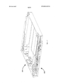
Со ссылкой на фиг. 1-16 показан оптоволоконный распределительный элемент 10 или элемент 10 согласно различным вариантам осуществления. Элементы 10 могут быть установлены индивидуально, при необходимости, в телекоммуникационном оборудовании, включающем в себя стойки, рамы или шкафы. Элементы 10 могут быть установлены группами или блоками 12, которые образуют штабелированную конструкцию. Согласно одному из вариантов осуществления вертикальный штабель из элементов 10 заполняет оптоволоконную распределительную стойку.With reference to FIG. 1-16, a fiber
В каждом из элементов 10 находятся оконцовки кабелей или другие компоненты кабелей, включая кабельные делители и/или кабельные сростки. Что касается оконцовок кабелей, то входящие кабели соединяются с выходящими кабелями через соединительные кабельные концы, которые соединены переходниками, как это будет раскрыто далее.Cable terminations or other cable components, including cable dividers and / or cable splices, are located in each of the
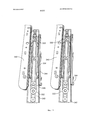
Каждый элемент включает в себя шасси 20 и подвижный лоток 24. Лоток 24 выполнен с возможностью перемещения посредством механизма 30 скольжения, включающего в себя одну или несколько шестерен 32 и комплект из двух зубчатых реек или линейных элементов 34.Each element includes a
Механизм 30 скольжения обеспечивает синхронизацию перемещения при укладке кабелей, входящих и выходящих из лотка 24. Входные точки 36 с каждой стороны шасси 20 позволяют фиксировать входные и выходные кабели, взаимосвязанные с каждым элементом 10. Ограничители 38 радиуса, взаимодействующие с каждым из механизмов 30 скольжения, перемещаются синхронизировано относительно шасси 20 и лотка 24, сохраняя провисание кабеля, но не вызывая скручивание, зажим или вытягивание кабеля.The sliding
Каждый лоток 24 включает в себя монтажную конструкцию 50, образующую один или более из следующих элементов: оконцовки кабелей, кабельные делители, кабельные сростки или другие кабельные компоненты. Как можно заметить, в монтажной конструкции 50 находятся переходники 52, которые позволяют соединять между собой два соединительных конца кабелей. Каждый лоток 24 включает в себя один или более каркасных элементов 56. В показанном примере обеспечено два каркасных элемента 56. Видно, что каждый из каркасных элементов 56 имеет Т-образную форму. Каждый лоток 24 также включает в себя два каркасных элемента 56, которые шарнирно установлены на шарниры 58. Верхний каркасный элемент 62 расположен над нижним каркасным элементом 64. Монтажная конструкция 50, связанная с каждым из каркасных элементов 62, 64, включает в себя один или более цельноформованных переходников 70. Переходники 70 включают в себя множество портов переходников для соединения с оптоволоконными разъемами 72. Проход 76, идущий от ограничителей 38 радиуса к переходникам 70, имеет, в целом, S-образную форму. Можно заметить, что проход 76 включает в себя верхний уровень 78 и нижний уровень 80 внутри. Участок 84 прохода 76 расположен рядом с шарнирами 58 для предотвращения вытягивания кабелей, способного привести к их повреждению, при поворотном перемещении каркасных элементов 56. Фланцы 86 и ограничители 90 радиуса помогают удерживать кабели 74 в проходе 76.Each
Лоток 24 включает в себя отверстия 96, обеспечивающие доступ техническому специалисту к оконцовкам кабелей в переходниках 70. Кроме того, Т-образная форма каркасных элементов 56 дополнительно упрощает доступ техническому специалисту к разъемам 72.
Кабели 74, входящие и выходящие из элемента 10, при необходимости могут быть прикреплены к кабельной опоре 100. Дополнительная защита кабелей от повреждений может быть обеспечена кабельными обмотками 102. Кроме того, для поддержки и защиты кабелей 74 могут быть использованы ограничители 106 радиуса.The
На фиг. 17-29 показаны кабельные разводки для элемента 10 согласно различным примерам.In FIG. 17-29 show cabling for
При необходимости, несколько питающих кабелей может быть уложено в нескольких элементах 10.If necessary, several power cables can be laid in
На фиг. 30-41 показаны элементы 210 согласно различным дополнительным вариантам осуществления. Элемент 210 включает в себя шасси 220 с подвижным лотком 224, установленным на механизм 230 скольжения, который обеспечивает синхронизированное перемещение ограничителей 238 радиуса. Каждый лоток 224 включает в себя два шарнирно установленных каркасных элемента 256. Каждый каркасный элемент 256 имеет средний участок, отделенный отверстиями 262 от боковых участков 264. На среднем участке 260 могут удерживаться оконцовки кабелей. Боковые участки 264 включают в себя ограничители 270 радиуса. Лоток 224 закрывается крышкой 266. Защелки 268 защелкивают лоток 224 на крышке 266 в закрытом положении.In FIG. 30-41,
Проход 276 простирается с любой из сторон лотка 224 для укладки кабелей в каждый из лотков 224. Кабели подаются к соответствующим каркасным элементам 256 на верхнем уровне 278 и нижнем уровне 280. Образуется, в целом, S-образный проход 276, причем проход 276 проходит вблизи от шарниров 258.A
Для удержания кабельных опор 286 и ограничителей 284 радиуса использовано соединение 288 «ласточкин хвост».To hold the cable supports 286 and radius stops 284, a dovetail joint 288 was used.
Отверстие 290 в лотке 224 обеспечивает доступ техническому специалисту к разъемам. Аналогичным образом отверстия 262 в каждом из каркасных элементов 256 обеспечивают доступ техническому специалисту к отдельным разъемам.
Для формирования блока 292 из нескольких элементов 210 используют планки 294 и крепеж 296. Планки 294 создают небольшие зазоры между элементами 210.To form a block 292 from
На фиг. 42-45 показан альтернативный механизм 330 скольжения в альтернативном элементе 310. Механизм 330 скольжения позволяет перемещать лотки и соответствующие ограничители радиуса и синхронизировать перемещение аналогично механизму 30, 230 скольжения. Альтернативный механизм 330 скольжения включает в себя два колесика 332 и два провода 334, 336. Колесики 332 расположены на второй части 342. Провода согнуты петлей в противоположных направлениях и соединены с первой частью 340 и третьей частью 344.In FIG. 42-45, an
На фиг. 46 и 47 показан альтернативный ограничитель 420 радиуса альтернативного элемента 410. Ограничитель 420 радиуса включает в себя фрикционные элементы 430, которые ограничивают степень скольжения кабелей, проходящих через ограничитель 420 радиуса, способствуя укладке кабелей. Фрикционные элементы 430 включают в себя гибкие пальцы, которые слегка прижимают кабели в ограничителе 420 радиуса для уменьшения или исключения перемещений кабелей в ограничителе 420 радиуса.In FIG. 46 and 47, an alternative radius stop 420 of an
На фиг. 48 и 49 показан альтернативный элемент 510 с механизмом 530 скольжения, который позволяет синхронизировать перемещения ограничителей 538 радиуса при укладке кабеля. Ограничители 538 радиуса также снабжены поворотной частью, позволяющей им поворачиваться назад при вытягивании лотка 524 из шасси 520. Подобное перемещение назад (поворот) позволяет уменьшить вытягивание кабелей, если оно возникает, позволяя выдвигать лоток полностью. Угол может быть любым. В одном из примеров величина угла составляет пятнадцать градусов.In FIG. 48 and 49 show an
На фиг. 50 и 51 показан альтернативный ограничитель 638 радиуса на механизмах скольжения альтернативных элементов 610. Элементы 610, в целом, имеют аналогичную конструкцию и функциональность по сравнению с ранее рассмотренными элементами. Ограничители 638 радиуса изгиба кабелей, в целом, имеют U-образную конструкцию, которая разводит кабели, идущие от и к элементу 610, соблюдая требования по минимальному радиусу изгиба.In FIG. 50 and 51, an
Ограничитель 638 радиуса кабелей U-образной формы имеет внутренний торец 621, внешний торец 623 и делитель 625, проходящий примерно от внутреннего торца 621 примерно до внешнего торца 623. Согласно одному из вариантов осуществления делитель 625 не доходит до внутреннего и внешнего торцов 621, 623 U-образного ограничителя 638 радиуса. Внешний торец 623 ограничителя 638 радиуса взаимодействует с кабельной направляющей 684, которая установлена на шасси 620 элемента 610 и предназначена для направления кабелей в лоток 624 и из лотка 624 элемента 610.The U-shaped
Делитель 625 ограничителя 638 радиуса образует два отдельных желоба 627, 629 для ограничителя 638 радиуса. Два желоба 627, 629 изолируют и разделяют кабели (например, входящие и выходящие) элемента 610 по двум отдельным траекториям. Согласно одному из примеров разводки кабелей два желоба 627, 629 могут направлять кабели на верхний и нижний уровни 678, 680 в направлении задней части лотка, сохраняя S-образную форму прохода 676, образованного в элементе 610. Делитель 625 ограничителя 638 радиуса включает в себя множество перегородок 631 для укладки кабелей, расположенных в нем и предназначенных для удержания кабелей внутри желобов 627, 629. Аналогичная перегородка 633 также находится в задней части лотка 624 для удержания кабелей, идущих на верхний и нижний уровни 678, 680. Перегородки 631 и 633 могут быть съемными, защелкиваемыми элементами.The
Перегородки 631 и 633 взаимодействуют с дополнительными пальцами 635 для укладки кабелей, расположенными как на ограничителе 638 радиуса изгиба, так и в задней части лотка 624, для удержания кабелей в пределах S-образного прохода 676.
Перечень ссылочных обозначенийReference List
10 элемент10 element
12 блок12 block
20 шасси20 chassis
24 лоток24 tray
30 механизм скольжения30 sliding mechanism
32 шестерни32 gears
34 рейка34 rail
36 входные точки36 entry points
38 ограничители радиуса38 radius limiters
50 монтажная конструкция50 mounting structure
52 переходники52 adapters
56 Т-образные каркасные элементы56 T-shaped frame elements
58 шарнир58 hinge
62 верхний каркасный элемент62 upper frame element
64 нижний каркасный элемент64 lower frame element
70 переходники70 adapters
72 разъемы72 connectors
74 кабели74 cables
76 проход76 passage
78 верхний уровень78 top level
80 нижний уровень80 lower level
84 участок84 plot
86 фланцы86 flanges
90 ограничители радиуса90 radius limiters
96 отверстия96 holes
100 кабельная опора100 cable support
102 кабельная обмотка102 cable winding
106 ограничители радиуса106 radius limiters
210 элемент210 element
220 шасси220 chassis
224 лоток224 tray
230 механизм скольжения230 sliding mechanism
238 ограничители радиуса238 radius limiters
256 каркасные элементы256 wireframe elements
258 шарниры258 hinges
260 средний участок260 middle section
262 отверстия262 holes
264 боковые участки264 side sections
266 крышка266 cover
268 защелки268 latches
270 ограничители радиуса270 radius limiters
276 проход276 passage
278 верхний уровень278 upper level
280 нижний уровень280 lower level
284 ограничители радиуса284 radius limiters
286 кабельные опоры286 cable supports
288 соединение «ласточкин хвост»288 dovetail compound
290 отверстие290 hole
292 блок292 block
294 планка294 strap
296 крепежи296 fasteners
310 элемент310 element
330 механизм скольжения330 sliding mechanism
332 колесики332 castors
334 провод334 wire
336 провод336 wire
340 первая часть340 first part
342 вторая часть342 second part
344 третья часть344 third part
410 элемент410 element
420 ограничитель радиуса420 radius limiter
430 фрикционные элементы430 friction elements
510 элемент510 element
520 шасси520 chassis
524 лоток524 tray
530 механизм скольжения530 sliding mechanism
538 ограничители радиуса538 radius limiters
610 элемент610 element
620 шасси620 chassis
621 внутренний торец ограничителя радиуса621 inner end of the radius limiter
623 внешний торец ограничителя радиуса623 outer end of the radius limiter
624 лоток624 tray
625 делитель625 divider
627 желоб627 gutter
629 желоб629 gutter
631 перегородка для укладки кабеля631 cable management partition
633 перегородка для укладки кабеля633 cable management partition
635 палец для укладки кабеля635 finger cable management
638 ограничитель радиуса638 radius limiter
676 проход676 passage
678 верхний уровень678 upper level
680 нижний уровень680 lower level
684 кабельная направляющая684 cable guide
Claims (14)
Applications Claiming Priority (9)
| Application Number | Priority Date | Filing Date | Title |
|---|---|---|---|
| US201361758266P | 2013-01-29 | 2013-01-29 | |
| US61/758,266 | 2013-01-29 | ||
| US201361798256P | 2013-03-15 | 2013-03-15 | |
| US61/798,256 | 2013-03-15 | ||
| US201361815500P | 2013-04-24 | 2013-04-24 | |
| US61/815,500 | 2013-04-24 | ||
| US201361892558P | 2013-10-18 | 2013-10-18 | |
| US61/892,558 | 2013-10-18 | ||
| PCT/EP2014/051714 WO2014118227A1 (en) | 2013-01-29 | 2014-01-29 | Optical fiber distribution system |
Publications (2)
| Publication Number | Publication Date |
|---|---|
| RU2015136443A RU2015136443A (en) | 2017-03-07 |
| RU2644083C2 true RU2644083C2 (en) | 2018-02-07 |
Family
ID=50023587
Family Applications (1)
| Application Number | Title | Priority Date | Filing Date |
|---|---|---|---|
| RU2015136443A RU2644083C2 (en) | 2013-01-29 | 2014-01-29 | System of distributing fibre-optic cables |
Country Status (12)
| Country | Link |
|---|---|
| US (8) | US9568699B2 (en) |
| EP (2) | EP3722854B1 (en) |
| CN (1) | CN105074525A (en) |
| AP (1) | AP2015008641A0 (en) |
| AU (2) | AU2014211445B2 (en) |
| BR (1) | BR112015016789B1 (en) |
| DK (1) | DK2951633T3 (en) |
| ES (2) | ES2953122T3 (en) |
| NZ (1) | NZ708968A (en) |
| RU (1) | RU2644083C2 (en) |
| SA (1) | SA515360823B1 (en) |
| WO (1) | WO2014118227A1 (en) |
Families Citing this family (45)
| Publication number | Priority date | Publication date | Assignee | Title |
|---|---|---|---|---|
| US11251608B2 (en) | 2010-07-13 | 2022-02-15 | Raycap S.A. | Overvoltage protection system for wireless communication systems |
| EP2490058A1 (en) * | 2011-02-17 | 2012-08-22 | Tyco Electronics Raychem BVBA | Optical fiber organizer with trays mounted on pivoting support |
| US9170391B2 (en) | 2011-10-07 | 2015-10-27 | Adc Telecommunications, Inc. | Slidable fiber optic connection module with cable slack management |
| WO2014118227A1 (en) | 2013-01-29 | 2014-08-07 | Tyco Electronics Raychem Bvba | Optical fiber distribution system |
| ES1148433Y (en) | 2013-04-24 | 2016-03-28 | Tyco Electronics Raychem Bvba | Cable assembly set |
| WO2014173896A1 (en) | 2013-04-24 | 2014-10-30 | Tyco Electronics Raychem Bvba | Universal mounting mechanism for mounting a telecommunications chassis to a telecommunications fixture |
| AU2014300959B2 (en) | 2013-06-28 | 2018-09-27 | CommScope Connectivity Belgium BVBA | Optical fiber distribution system with staggered cable guides |
| WO2016156524A1 (en) | 2015-03-31 | 2016-10-06 | CommScope Connectivity Belgium BVBA | Telecommunications module with hingeable input |
| DK3278159T3 (en) | 2015-04-03 | 2023-11-20 | CommScope Connectivity Belgium BVBA | TELECOMMUNICATION DISTRIBUTION ELEMENTS |
| US9851523B2 (en) | 2015-09-22 | 2017-12-26 | Go!Foton Holdings, Inc. | Apparatus for cable routing |
| JP6459876B2 (en) * | 2015-09-25 | 2019-01-30 | 株式会社オートネットワーク技術研究所 | Connector mounting structure |
| US10802237B2 (en) | 2015-11-03 | 2020-10-13 | Raycap S.A. | Fiber optic cable management system |
| US9971119B2 (en) | 2015-11-03 | 2018-05-15 | Raycap Intellectual Property Ltd. | Modular fiber optic cable splitter |
| EP3390753B1 (en) | 2015-12-16 | 2021-03-03 | CommScope Connectivity Belgium BVBA | Telecommunications distribution elements |
| EP3510432A1 (en) * | 2016-09-08 | 2019-07-17 | CommScope Connectivity Belgium BVBA | Telecommunications distribution elements |
| AR109532A1 (en) * | 2016-09-29 | 2018-12-19 | Furukawa Ind S A Produtos Eletricos | OPTICAL FRAME |
| EP3571566A4 (en) | 2017-01-20 | 2021-01-06 | Raycap, S.A. | Power transmission system for wireless communication systems |
| US10291969B2 (en) * | 2017-02-14 | 2019-05-14 | Go!Foton Holdings, Inc. | Rear cable management |
| US10310206B2 (en) * | 2017-05-22 | 2019-06-04 | Go!Foton Holdings, Inc. | Apparatus for cable routing |
| US10670822B2 (en) | 2017-06-28 | 2020-06-02 | Afl Telecommunications Llc | High density patch panel with modular cassettes |
| EP3759535A4 (en) | 2018-02-28 | 2021-11-10 | CommScope Technologies LLC | HOUSING ARRANGEMENT FOR TELECOMMUNICATION EQUIPMENT |
| US11635578B2 (en) | 2018-04-17 | 2023-04-25 | CommScope Connectivity Belgium BVBA | Telecommunications distribution elements |
| CA3052811A1 (en) * | 2018-08-24 | 2020-02-24 | Vincent PILON | Flexible cable guide |
| US10971928B2 (en) | 2018-08-28 | 2021-04-06 | Raycap Ip Assets Ltd | Integrated overvoltage protection and monitoring system |
| WO2020043911A1 (en) | 2018-08-31 | 2020-03-05 | CommScope Connectivity Belgium BVBA | Frame assemblies for optical fiber distribution elements |
| WO2020043918A1 (en) | 2018-08-31 | 2020-03-05 | CommScope Connectivity Belgium BVBA | Frame assemblies for optical fiber distribution elements |
| EP3844546A1 (en) | 2018-08-31 | 2021-07-07 | CommScope Connectivity Belgium BVBA | Frame assemblies for optical fiber distribution elements |
| EP3844972B1 (en) | 2018-08-31 | 2022-08-03 | CommScope Connectivity Belgium BVBA | Frame assemblies for optical fiber distribution elements |
| EP3844547A1 (en) | 2018-08-31 | 2021-07-07 | CommScope Connectivity Belgium BVBA | Frame assemblies for optical fiber distribution elements |
| EP3871028B1 (en) | 2018-10-23 | 2025-06-18 | CommScope Connectivity Belgium BVBA | Frame assemblies for optical fiber distribution elements |
| EP3911987B1 (en) | 2019-01-15 | 2023-08-09 | CommScope Connectivity Belgium BVBA | Splice patch arrangement with movable adapters |
| WO2020152347A1 (en) | 2019-01-25 | 2020-07-30 | CommScope Connectivity Belgium BVBA | Frame assemblies for optical fiber distribution elements |
| US10585256B1 (en) * | 2019-03-29 | 2020-03-10 | Corning Research & Development Corporation | Terminal of an optical fiber network having a bypass module |
| US11237348B2 (en) | 2019-04-17 | 2022-02-01 | Afl Ig Llc | Patch panel with lifting cassette removal |
| US11677164B2 (en) | 2019-09-25 | 2023-06-13 | Raycap Ip Assets Ltd | Hybrid antenna distribution unit |
| WO2021071844A1 (en) | 2019-10-07 | 2021-04-15 | Commscope Technologies Llc | Fiber distribution hub including sealed splice module |
| HRP20251143T1 (en) | 2020-01-22 | 2025-11-21 | CommScope Connectivity Belgium BVBA | CABLE TERMINATION UNITS FOR FIBER OPTIC DISTRIBUTION ELEMENTS |
| US12099246B2 (en) | 2020-01-24 | 2024-09-24 | CommScope Connectivity Belgium BVBA | Telecommunications distribution elements |
| WO2021156389A1 (en) | 2020-02-07 | 2021-08-12 | CommScope Connectivity Belgium BVBA | Telecommunications module arrangements |
| EP3919955B1 (en) * | 2020-06-04 | 2024-05-15 | CommScope Connectivity Belgium BV | Cable manager part for telecommunications tray assembly |
| EP3971622A1 (en) | 2020-07-02 | 2022-03-23 | Go!Foton Holdings, Inc. | Intelligent optical switch |
| WO2022008546A1 (en) | 2020-07-09 | 2022-01-13 | Commscope Connectivy Belgium Bv | Telecommunications arrangements |
| US11921339B2 (en) * | 2020-09-17 | 2024-03-05 | Panduit Corp. | Optical distribution and splice frame including vertical cable managers |
| EP3992683B1 (en) | 2020-11-02 | 2025-07-09 | CommScope Connectivity Belgium BV | Splice patch arrangement with movable adapters |
| US12237134B2 (en) | 2021-12-28 | 2025-02-25 | Raycap Ip Assets Ltd | Circuit protection for hybrid antenna distribution units |
Citations (3)
| Publication number | Priority date | Publication date | Assignee | Title |
|---|---|---|---|---|
| US7120348B2 (en) * | 2000-01-24 | 2006-10-10 | Adc Telecommunications, Inc. | Cable management panel with sliding drawer |
| US20080205843A1 (en) * | 2007-02-28 | 2008-08-28 | Guy Castonguay | Fiber optic drop terminals for multiple dwelling units |
| WO2011163464A2 (en) * | 2010-06-23 | 2011-12-29 | Adc Telecommunications, Inc. | Telecommunications assembly |
Family Cites Families (347)
| Publication number | Priority date | Publication date | Assignee | Title |
|---|---|---|---|---|
| US2864656A (en) | 1954-06-25 | 1958-12-16 | Yorinks Alexander | Slide mechanism |
| NL193890A (en) | 1954-12-27 | |||
| US3901564A (en) | 1973-10-29 | 1975-08-26 | Henry P Armstrong | Drawer extensible slide chassis |
| US4070076A (en) | 1977-05-05 | 1978-01-24 | The Raymond Lee Organization, Inc. | Drawer sliding device |
| DE2735106C2 (en) | 1977-08-04 | 1983-09-01 | AEG-Telefunken Nachrichtentechnik GmbH, 7150 Backnang | Cable set for a telecommunication cable |
| US4172625A (en) | 1977-12-15 | 1979-10-30 | Comerco, Inc. | Drawer extenders |
| DE2918572A1 (en) | 1978-06-13 | 1980-01-03 | Blum Gmbh Julius | EXTENSION GUIDE SET FOR DRAWERS |
| DE2918309C2 (en) | 1979-05-07 | 1982-11-04 | Heino Schulz Kunststoffverarbeitung, 5300 Bonn | Drawer pull-out device |
| JPS56141025A (en) | 1980-04-03 | 1981-11-04 | Nissan Motor Co Ltd | Fuel control ling device |
| US4373776A (en) | 1980-06-30 | 1983-02-15 | Northern Telecom Limited | Protection case for optical fiber splices |
| US4359262A (en) | 1980-06-30 | 1982-11-16 | Northern Telecom Limited | Tray for organizing optical fiber splices and enclosures embodying such trays |
| JPS58109707U (en) | 1982-01-19 | 1983-07-26 | 日本電気株式会社 | Terminal board storage device |
| FR2531576A1 (en) | 1982-08-04 | 1984-02-10 | Cit Alcatel | CONNECTION AND OPTO-ELECTRONIC INTERFACE |
| FR2531544B1 (en) | 1982-08-04 | 1985-01-25 | Cit Alcatel | OPTICAL CABLE HEAD |
| JPS5974523A (en) | 1982-10-21 | 1984-04-27 | Furukawa Electric Co Ltd:The | Optical fiber connection box |
| JPS5974523U (en) | 1982-11-06 | 1984-05-21 | 日本電信電話株式会社 | magnetic disk |
| FR2538918A1 (en) | 1983-01-05 | 1984-07-06 | Telecommunications Sa | FIBER OPTIC CONNECTION AND BREWING BOX |
| DE3308682C2 (en) | 1983-03-11 | 1985-12-05 | Krone Gmbh, 1000 Berlin | Matrix main distributor |
| US4494806A (en) | 1983-05-13 | 1985-01-22 | Leslie Metal Arts Company | Spring loaded drawer assembly with mechanical damping |
| US4595255A (en) | 1983-08-24 | 1986-06-17 | Fiberlan, Inc. | Optical fiber wiring center |
| FR2556895B1 (en) | 1983-12-20 | 1986-12-19 | Lignes Telegraph Telephon | DEVICE FOR CONNECTING CABLES, PARTICULARLY WITH OPTICAL FIBERS |
| DE3347621A1 (en) | 1983-12-30 | 1985-07-11 | Wilhelm Sedlbauer GmbH Fabrik für Feinmechanik und Elektronik, 8000 München | DISTRIBUTION RACK FOR FIBERGLASS CABLE ENDS |
| JPS60169811A (en) | 1984-02-14 | 1985-09-03 | Furukawa Electric Co Ltd:The | Containing device for connection excessive length of optical fiber |
| GB2138057B (en) | 1984-04-11 | 1987-09-30 | Tekken Constr Co | Method of building strengthened, embanked foundation |
| US4630886A (en) | 1984-04-16 | 1986-12-23 | At&T Bell Laboratories | Lightguide distributing unit |
| JPS60169811U (en) | 1984-04-18 | 1985-11-11 | 株式会社小松製作所 | proportional electromagnetic solenoid |
| JPS6155607A (en) | 1984-08-28 | 1986-03-20 | Fujitsu Ltd | Light distributing board |
| JPS6190104A (en) | 1984-10-09 | 1986-05-08 | Nec Corp | Optical adapter installation structure |
| CA1249741A (en) | 1984-10-25 | 1989-02-07 | Michael J. Donaldson | Optical cable terminating equipment |
| JPH0124807Y2 (en) | 1984-11-20 | 1989-07-26 | ||
| FR2575020B1 (en) | 1984-12-14 | 1987-02-13 | Nozick Jacques | DISTRIBUTOR FOR OPTICAL CABLES |
| US4699455A (en) | 1985-02-19 | 1987-10-13 | Allen-Bradley Company | Fiber optic connector |
| DE3511653A1 (en) | 1985-03-29 | 1986-10-02 | Siemens AG, 1000 Berlin und 8000 München | BASE WITH INSERT FOR A COUPLING PANEL BETWEEN FIBERGLASS CABLES |
| US4765710A (en) | 1985-07-30 | 1988-08-23 | Siemens Aktiengesellschaft | Distributing frame for optical waveguides and the like |
| FR2587127B1 (en) | 1985-09-06 | 1987-10-23 | Valleix Paul | STRUCTURE FOR OPTICAL CONNECTIONS |
| US4792203A (en) | 1985-09-17 | 1988-12-20 | Adc Telecommunications, Inc. | Optical fiber distribution apparatus |
| US4737039A (en) | 1986-12-08 | 1988-04-12 | Knape & Vogt Manufacturing Company | Drawer rail carrier roller mount |
| US4840449A (en) | 1988-01-27 | 1989-06-20 | American Telephone And Telegraph Company, At&T Bell Laboratories | Optical fiber splice organizer |
| US4820007A (en) | 1988-02-12 | 1989-04-11 | American Telephone And Telegraph Company At&T Bell Laboratories | Cable closure and methods of assembling |
| US4898448A (en) | 1988-05-02 | 1990-02-06 | Gte Products Corporation | Fiber distribution panel |
| US4900123A (en) | 1988-08-29 | 1990-02-13 | Gte Products Corporation | 1550 nm fiber distribution panel |
| DE3836273C2 (en) | 1988-10-25 | 1997-05-07 | Standard Praezision Gmbh | Synchronized three-part telescopic rail for tension members |
| DE3838428A1 (en) | 1988-11-12 | 1990-05-31 | Philips Patentverwaltung | SWITCH DISTRIBUTOR FOR THE PRODUCTION OF FREELY SELECTABLE OPTICAL CONNECTORS |
| US5071211A (en) | 1988-12-20 | 1991-12-10 | Northern Telecom Limited | Connector holders and distribution frame and connector holder assemblies for optical cable |
| US5013121A (en) | 1989-06-29 | 1991-05-07 | Anton Mark A | Optical fiber storage container |
| US5316243A (en) | 1989-07-31 | 1994-05-31 | Adc Telecommunications, Inc. | Optic cable management |
| US5067678A (en) | 1989-07-31 | 1991-11-26 | Adc Telecommunications, Inc. | Optic cable management system |
| US4995688A (en) | 1989-07-31 | 1991-02-26 | Adc Telecommunications, Inc. | Optical fiber distribution frame |
| US4986762A (en) | 1989-08-15 | 1991-01-22 | Minnesota Mining And Manufacturing Company | Termination module for use in an array of modules |
| US4971421A (en) | 1989-09-29 | 1990-11-20 | Reliance Comm/Tec Corporation | Fiber optic splice and patch enclosure |
| US5142606A (en) | 1990-01-22 | 1992-08-25 | Porta Systems Corp. | Optical fiber cable distribution frame and support |
| US5100221A (en) | 1990-01-22 | 1992-03-31 | Porta Systems Corp. | Optical fiber cable distribution frame and support |
| US4991928A (en) | 1990-02-20 | 1991-02-12 | Siecor Corporation | Movable clamp for fiber optic enclosures |
| US5142607A (en) | 1990-03-20 | 1992-08-25 | Rittal-Werk Rudolf Loh Gmbh & Co. Kg | Splice box for optical wave guide |
| US5174675A (en) | 1990-05-07 | 1992-12-29 | Inventio Ag | Guide bar for an elevator door |
| FR2663917B1 (en) | 1990-06-29 | 1993-06-04 | Cit Alcatel | MODULAR DEVICE FOR STORING RESERVES OF TRANSMISSION SUPPORT ON LINKS, PARTICULARLY FIBER OPTIC. |
| US5066149A (en) | 1990-09-11 | 1991-11-19 | Adc Telecommunications, Inc. | Splice tray with slack take-up |
| ES2100189T3 (en) | 1990-10-04 | 1997-06-16 | Alcatel Cable Interface | OPTICAL CONNECTION BOX. |
| US5138688A (en) | 1990-11-09 | 1992-08-11 | Northern Telecom Limited | Optical connector holder assembly |
| US5127082A (en) | 1991-03-22 | 1992-06-30 | The Siemon Company | Fiber optic patch panel |
| US5129030A (en) | 1991-05-30 | 1992-07-07 | At&T Bell Laboratories | Movable lightguide connector panel |
| FR2678076B1 (en) | 1991-06-20 | 1994-09-23 | Cit Alcatel | MODULE FOR STORING A TRANSMISSION SUPPORT RESERVE ON A LINK, PARTICULARLY WITH OPTICAL FIBER AND STORAGE DEVICE COMPRISING A SET OF SUCH MODULES. |
| US5167001A (en) | 1991-09-03 | 1992-11-24 | Northern Telecom Limited | Optical fiber storage and connector tray and shelf and tray assembly |
| DE4133375C1 (en) | 1991-10-05 | 1993-04-22 | Krone Ag | |
| FR2682488B1 (en) | 1991-10-15 | 1994-01-21 | Bruno Capelle | MODULAR CABLES HEAD WITH LARGE CAPACITY FIBER OPTICS. |
| ES1019586Y (en) | 1991-12-12 | 1992-11-01 | Telefonica De Espana, S.A. | TERMINAL JOINT AND MODULAR OPTICAL DISTRIBUTION. |
| US5247603A (en) | 1992-01-24 | 1993-09-21 | Minnesota Mining And Manufacturing Company | Fiber optic connection system with exchangeable cross-connect and interconnect cards |
| FR2687800B1 (en) | 1992-02-21 | 1994-04-08 | Mars Actel | ADAPTABLE CASSETTE FOR LOVING AND SPLICING OPTICAL FIBERS. |
| FR2687744B1 (en) | 1992-02-21 | 1994-04-08 | Mars Actel | SET OF ARTICULATED FLAT MODULES. |
| US5202942A (en) | 1992-04-03 | 1993-04-13 | Amp Incorporated | Cable termination member for fiber optic connectors having improved strain relief |
| US5275064A (en) | 1992-06-12 | 1994-01-04 | General Devices Co., Inc. | Extensible platform with cable drive system |
| US5240209A (en) | 1992-11-17 | 1993-08-31 | Telect, Inc. | Telecommunication multiple cable carrier |
| US5323480A (en) | 1992-11-25 | 1994-06-21 | Raychem Corporation | Fiber optic splice closure |
| US5335349A (en) | 1992-12-14 | 1994-08-02 | Telect, Inc. | Telecommunication overhead cable distribution assembly |
| FR2703160B1 (en) | 1993-03-26 | 1995-06-02 | Corning Inc | Cassette for optical fiber device, fitted with a bundle of flexible fiber protection tubes. |
| US5363467A (en) | 1993-05-28 | 1994-11-08 | Minnesota Mining And Manufacturing Company | Compact fiber optic housing |
| US5339379A (en) | 1993-06-18 | 1994-08-16 | Telect, Inc. | Telecommunication fiber optic cable distribution apparatus |
| US5412751A (en) | 1993-08-31 | 1995-05-02 | The Siemon Company | Retrofittable multimedia patch management system |
| GB9318633D0 (en) | 1993-09-08 | 1993-10-27 | Raychem Sa Nv | Organization of optical fibres |
| GB9318632D0 (en) * | 1993-09-08 | 1993-10-27 | Raychem Sa Nv | Optical fibre organizer |
| US5353367A (en) | 1993-11-29 | 1994-10-04 | Northern Telecom Limited | Distribution frame and optical connector holder combination |
| US5490229A (en) | 1993-12-08 | 1996-02-06 | At&T Ipm Corp. | Slidably mounted optical fiber distribution tray |
| TW232757B (en) | 1994-01-21 | 1994-10-21 | Adc Telecommunications Inc | High-density fiber distribution frame |
| US5402515A (en) | 1994-03-01 | 1995-03-28 | Minnesota Mining And Manufacturing Company | Fiber distribution frame system, cabinets, trays and fiber optic connector couplings |
| DE4413136C1 (en) | 1994-04-19 | 1995-05-04 | Loh Kg Rittal Werk | Optical-fibre splice box |
| US5511144A (en) | 1994-06-13 | 1996-04-23 | Siecor Corporation | Optical distribution frame |
| GB2292466B (en) | 1994-08-15 | 1997-09-10 | Pirelli General Plc | Guiding optical fibres in ducts |
| US5530783A (en) | 1994-08-31 | 1996-06-25 | Berg Technology, Inc. | Backplane optical fiber connector for engaging boards of different thicknesses and method of use |
| WO1996010203A1 (en) | 1994-09-28 | 1996-04-04 | Telephone Cables Limited | A splice tray |
| US5509096A (en) | 1994-10-28 | 1996-04-16 | Syntec Inc. | Receptacle and plug fiber optic connector assembly |
| DE4442823A1 (en) | 1994-12-01 | 1996-06-05 | Siemens Ag | Cassette module for optical fibers |
| DE29504191U1 (en) | 1995-03-01 | 1996-03-28 | Krone Ag, 14167 Berlin | Insert for receiving devices of the LWL technology |
| US5613030A (en) | 1995-05-15 | 1997-03-18 | The Whitaker Corporation | High density fiber optic interconnection enclosure |
| US5724469A (en) | 1996-01-26 | 1998-03-03 | Ortronics, Inc. | Adjustable fiber storage plate |
| US5836148A (en) | 1996-02-06 | 1998-11-17 | Kunimorikagaku Ltd. | Cable chain |
| US5811055A (en) | 1996-02-06 | 1998-09-22 | Geiger; Michael B. | Torch mounted gas scavaging system for manual and robotic welding and cutting torches |
| DE69607132T2 (en) | 1996-02-17 | 2000-08-31 | Horizon International, Inc. | Device for feeding paper for a book binding machine |
| DE19611770C2 (en) | 1996-03-14 | 1998-04-09 | Krone Ag | Manageable splice cassette |
| US5715348A (en) | 1996-03-27 | 1998-02-03 | Next Level Communications | Fiber management system and method for routing optical fiber having a minimum bend radius |
| EP0801317B1 (en) | 1996-04-12 | 2002-06-26 | Telephone Cables Limited | Management of optical fibre |
| EP0834270B1 (en) | 1996-10-07 | 2003-07-30 | Julius Blum Gesellschaft m.b.H. | Drawer slide fitting |
| WO1998041891A1 (en) | 1997-03-17 | 1998-09-24 | Tii Industries, Inc. | Fiber optic cable bend radius controller |
| US5802237A (en) | 1997-04-18 | 1998-09-01 | Minnesota Mining And Manufacturing Company | Optical fiber organizer |
| US6022150A (en) | 1997-04-30 | 2000-02-08 | The Whitaker Corporation | Fiber optic connector |
| US6128946A (en) | 1997-06-26 | 2000-10-10 | Crane Nuclear, Inc. | Method and apparatus for on-line detection of leaky emergency shut down or other valves |
| US5975769A (en) | 1997-07-08 | 1999-11-02 | Telect, Inc. | Universal fiber optic module system |
| US5971626A (en) | 1997-08-29 | 1999-10-26 | Siecor Corporation | Fiber optic connector and connector sleeve assembly |
| US6009224A (en) * | 1997-11-06 | 1999-12-28 | Allen; Barry Wayne | Fiber optic organizer with lockable trays and method of accessing a tray |
| US5923753A (en) | 1997-11-17 | 1999-07-13 | Adc Telecommunications, Inc. | Optic cable exit trough with bypass |
| US5946440A (en) | 1997-11-17 | 1999-08-31 | Adc Telecommunications, Inc. | Optical fiber cable management device |
| US6027252A (en) | 1997-12-19 | 2000-02-22 | The Whitaker Corporation | Simplified fiber optic receptacle |
| US5966492A (en) | 1997-12-19 | 1999-10-12 | Antec Corporation | Apparatus for storing and splicing optical fibers |
| GB9801198D0 (en) | 1998-01-21 | 1998-03-18 | Raychem Sa Nv | Optical fibre assembly |
| US5978540A (en) | 1998-04-23 | 1999-11-02 | Antec Corporation | Apparatus for interconnecting optical fibers |
| US6208796B1 (en) | 1998-07-21 | 2001-03-27 | Adc Telecommunications, Inc. | Fiber optic module |
| US6085003A (en) | 1998-07-28 | 2000-07-04 | Us Conec Ltd | Multifiber connector having a free floating ferrule |
| FR2782171B1 (en) | 1998-08-04 | 2001-11-30 | Pouyet Sa | FIBER OPTIC CABLES CONNECTION DEVICE |
| US6263141B1 (en) | 1998-09-09 | 2001-07-17 | Adc Telecommunications, Inc. | Optical fiber cable management device including storage tray |
| US6076908A (en) | 1998-09-17 | 2000-06-20 | Platt And Labonia Co. | Drawer for storage cabinet |
| US6215938B1 (en) | 1998-09-21 | 2001-04-10 | Adc Telecommunications, Inc. | Fiber optic cabinet and tray |
| US6496638B1 (en) * | 1998-10-23 | 2002-12-17 | Lucent Technologies Inc. | Optical fiber cassette |
| US6468112B1 (en) | 1999-01-11 | 2002-10-22 | Adc Telecommunications, Inc. | Vertical cable management system with ribcage structure |
| US6760531B1 (en) | 1999-03-01 | 2004-07-06 | Adc Telecommunications, Inc. | Optical fiber distribution frame with outside plant enclosure |
| JP2000286574A (en) | 1999-03-31 | 2000-10-13 | Nec Eng Ltd | Cable-clamping unit |
| US6236795B1 (en) | 1999-06-07 | 2001-05-22 | E. Walter Rodgers | High-density fiber optic cable distribution frame |
| GB9913264D0 (en) | 1999-06-09 | 1999-08-04 | Raychem Sa Nv | Detent for optical fibres |
| US6256444B1 (en) | 1999-09-21 | 2001-07-03 | Antec Corporation | Adjustable guide for organizing optical fibers in an equipment rack |
| GB9926487D0 (en) | 1999-11-10 | 2000-01-12 | Raychem Sa Nv | Optical fibre management |
| US6226436B1 (en) | 1999-11-18 | 2001-05-01 | Lucent Technologies, Inc. | Fiber optical pedestal |
| DE19956067A1 (en) | 1999-11-22 | 2001-05-23 | Rxs Kabelgarnituren Gmbh & Co | Cassette for accommodating optical fibres, surplus lengths, splices, etc., has differently shaped splice holders for various types of splice protection elements, and add-on elements for adapting to required use |
| US6438310B1 (en) | 2000-01-24 | 2002-08-20 | Adc Telecommunications, Inc. | Cable management panel with sliding drawer |
| US6301424B1 (en) | 2000-04-13 | 2001-10-09 | Lucent Technologies Inc. | Distribution frame cable routing apparatus |
| US6439523B1 (en) | 2000-06-02 | 2002-08-27 | Panduit Corp. | Universal mounting system for a fiber optic management center |
| US20030020379A1 (en) | 2000-07-13 | 2003-01-30 | Larsen Lars R. | Cabinet with a removable and reversible door |
| US6612515B1 (en) | 2000-08-28 | 2003-09-02 | Adc Telecommunications, Inc. | Telecommunications cable storage spool |
| US6360050B1 (en) | 2000-09-08 | 2002-03-19 | Telect, Inc. | High density fiber distribution tray system |
| US6381393B1 (en) | 2000-11-08 | 2002-04-30 | Adc Telecommunications, Inc. | Fanning strip for cable management panel |
| US6845207B2 (en) | 2001-02-12 | 2005-01-18 | Fiber Optic Network Solutions Corp. | Optical fiber enclosure system |
| US6625374B2 (en) | 2001-03-07 | 2003-09-23 | Adc Telecommunications, Inc. | Cable storage spool |
| US6600866B2 (en) | 2001-03-13 | 2003-07-29 | 3M Innovative Properties Company | Filament organizer |
| US7266280B2 (en) | 2001-03-16 | 2007-09-04 | Avago Technologies Fiber Ip (Singapore) Pte. Ltd. | Cable storage device providing continuous adjustability with controlled bend radius |
| US6539161B2 (en) | 2001-03-16 | 2003-03-25 | Adc Telecommunications, Inc. | Cable routing clip |
| GB0108255D0 (en) | 2001-04-02 | 2001-05-23 | Tyco Electronics Raychem Nv | Optical fibre organiser |
| US6674952B2 (en) | 2001-04-30 | 2004-01-06 | Telect, Inc. | Fiber optic cable bend radius protection system |
| US6792190B2 (en) * | 2001-06-01 | 2004-09-14 | Telect, Inc. | High density fiber optic splitter/connector tray system |
| US7079744B2 (en) * | 2001-07-06 | 2006-07-18 | Adc Telecommunications, Inc. | Cable management panel with sliding drawer and methods |
| US6819857B2 (en) | 2001-10-12 | 2004-11-16 | Adc Telecommunications, Inc. | Rotating vertical fiber tray and methods |
| US6594434B1 (en) | 2001-10-26 | 2003-07-15 | Ciena Corporation | Fiber optic cables management and measurement apparatus |
| FR2832225B1 (en) | 2001-11-13 | 2004-08-27 | Nexans | HIGH DENSITY OPTICAL DISTRIBUTOR AND METHOD FOR THE GARAGE OF SUCH A DISTRIBUTOR |
| FR2832226B1 (en) | 2001-11-13 | 2004-10-22 | Nexans | OPTICAL FIBER DISTRIBUTION AND CONNECTION MODULE FOR AN OPTICAL DISTRIBUTOR |
| US6591051B2 (en) | 2001-11-16 | 2003-07-08 | Adc Telecommunications, Inc. | Fiber termination block with angled slide |
| DE20200065U1 (en) | 2002-01-03 | 2003-03-06 | CCS Technology, Inc., Wilmington, Del. | Splice cassette |
| FR2836560B1 (en) | 2002-02-25 | 2004-06-18 | Nexans | LOVING CASSETTE FOR OPTICAL FIBERS |
| FR2836561B1 (en) | 2002-02-28 | 2004-06-18 | Nexans | CASSETTE FOR LOVING AND HOLDING SPLICES BETWEEN CONDUCTORS AND ORGANIZER OF A PLURALITY OF SAID CASSETTES |
| US6909833B2 (en) | 2002-03-15 | 2005-06-21 | Fiber Optic Network Solutions, Inc. | Optical fiber enclosure system using integrated optical connector and coupler assembly |
| US6850685B2 (en) | 2002-03-27 | 2005-02-01 | Adc Telecommunications, Inc. | Termination panel with pivoting bulkhead and cable management |
| US7116777B2 (en) | 2002-04-05 | 2006-10-03 | Adc Telecommunications, Inc. | Termination frame with modules and method |
| CN100374892C (en) | 2002-04-12 | 2008-03-12 | 泰科电子雷伊化学有限公司 | Optical path enclosure |
| US6937807B2 (en) | 2002-04-24 | 2005-08-30 | Adc Telecommunications, Inc. | Cable management panel with sliding drawer |
| MY131063A (en) | 2002-05-17 | 2007-07-31 | Harn Marketing Sdn Bhd | Guide rails pull-out drawer/equipment |
| US6711339B2 (en) | 2002-05-31 | 2004-03-23 | Adc Telecommunications, Inc. | Fiber management module with cable storage |
| US6957920B2 (en) | 2002-06-24 | 2005-10-25 | Corning Cable Systems Llc | Ferrule assembly having highly protruding optical fibers and an associated fabrication method |
| US6715619B2 (en) | 2002-07-22 | 2004-04-06 | Adc Telecommunications, Inc. | Fiber management drawer and patch panel |
| US6677520B1 (en) | 2002-07-22 | 2004-01-13 | Adc Telecommunications, Inc. | Fanning tray |
| US6748155B2 (en) | 2002-07-22 | 2004-06-08 | Adc Telecommunications, Inc. | Fiber management drawer and sliding cable slack limiter |
| US6981750B2 (en) | 2002-09-16 | 2006-01-03 | Adc Telecommunications, Inc. | Retainer for hinged door |
| US6796437B2 (en) | 2002-09-16 | 2004-09-28 | Adc Telecommunications, Inc. | Cable trough |
| CN100420970C (en) | 2002-10-11 | 2008-09-24 | 3M创新有限公司 | Drawer for managing fiber optics |
| US7086539B2 (en) | 2002-10-21 | 2006-08-08 | Adc Telecommunications, Inc. | High density panel with rotating tray |
| US6804447B2 (en) | 2002-11-05 | 2004-10-12 | Adc Telecommunications, Inc. | Fiber panel with integrated couplers |
| DE10255561A1 (en) * | 2002-11-22 | 2004-06-09 | Krone Gmbh | Method and device for coupling optical fibers |
| US6768860B2 (en) | 2002-12-05 | 2004-07-27 | Jds Uniphase Inc. | High density fiber optic module |
| US6865331B2 (en) * | 2003-01-15 | 2005-03-08 | Adc Telecommunications, Inc. | Rotating radius limiter for cable management panel and methods |
| US6809258B1 (en) | 2003-02-24 | 2004-10-26 | Cisco Technology, Inc. | Apparatus for cable routing management |
| US6853795B2 (en) | 2003-03-05 | 2005-02-08 | Corning Cable Systems Llc | High density fiber optic distribution frame |
| US7364244B2 (en) | 2003-05-14 | 2008-04-29 | Hewlett-Packard Development Company | User-controllable latching carrier rail system |
| JP4321111B2 (en) | 2003-05-16 | 2009-08-26 | 日本電気株式会社 | OPTICAL MODULE, METHOD FOR RELEASE LOCK STATUS OF OPTICAL MODULE AND CAGE |
| US6870734B2 (en) | 2003-05-30 | 2005-03-22 | Adc Telecommunications, Inc. | Fiber containment system |
| US20050017614A1 (en) | 2003-06-23 | 2005-01-27 | Paul Cirocco | Split lock arm for three-piece slide assembly |
| US7171099B2 (en) | 2003-07-31 | 2007-01-30 | Adc Telecommunications, Inc. | Slide arrangement for cable drawer |
| KR200337929Y1 (en) | 2003-10-23 | 2004-01-13 | 허필규 | A Housing for purchase of optical fiber adapter |
| US6920274B2 (en) | 2003-12-23 | 2005-07-19 | Adc Telecommunications, Inc. | High density optical fiber distribution frame with modules |
| US6944383B1 (en) | 2004-04-12 | 2005-09-13 | Adc Telecommunications, Inc. | Cable management panel with sliding drawer and methods |
| US7527436B2 (en) | 2004-07-19 | 2009-05-05 | Molex Incorporated | Ferrule with tilt correction |
| US7317619B2 (en) | 2004-08-02 | 2008-01-08 | International Business Machines Corporation | Apparatus for inserting and ejecting an electronic enclosure within a cabinet |
| RU45207U1 (en) | 2004-10-14 | 2005-04-27 | Открытое Акционерное Общество "ВЭЛАН" | CABLE INPUTS (OPTIONS) |
| JP4329669B2 (en) | 2004-10-21 | 2009-09-09 | ソニー株式会社 | Electronics |
| US7171100B2 (en) | 2004-11-03 | 2007-01-30 | Adc Telecommunications, Inc. | Optical fiber slack storage tray for distribution cabinet |
| US7376322B2 (en) | 2004-11-03 | 2008-05-20 | Adc Telecommunications, Inc. | Fiber optic module and system including rear connectors |
| US7470139B2 (en) | 2004-11-26 | 2008-12-30 | Fujitsu Component Limited | Transceiver module |
| US7362942B2 (en) | 2005-03-02 | 2008-04-22 | Adc Telecommunications, Inc. | System and method of grounding fiber storage trays |
| US7376323B2 (en) | 2005-05-25 | 2008-05-20 | Adc Telecommunications, Inc. | Fiber optic adapter module |
| US7460758B2 (en) | 2005-06-03 | 2008-12-02 | Telect Inc. | Fiber management system |
| US20070003204A1 (en) | 2005-06-30 | 2007-01-04 | Elli Makrides-Saravanos | Methods and apparatus for splitter modules and splitter module housings |
| US7406240B2 (en) | 2005-07-21 | 2008-07-29 | Ortronics, Inc. | Patch panel for fiber optic network |
| US7416349B2 (en) | 2005-07-27 | 2008-08-26 | Adc Telecommunications, Inc. | Fiber optic adapter module |
| CN2821666Y (en) | 2005-08-02 | 2006-09-27 | 鸿富锦精密工业(深圳)有限公司 | Extension locking device |
| US7397996B2 (en) | 2005-08-02 | 2008-07-08 | Adc Telecommunications, Inc. | Cable management panel with rear entry |
| JP4875338B2 (en) | 2005-09-13 | 2012-02-15 | ソニー株式会社 | Information processing apparatus and method, and program |
| US7302153B2 (en) | 2005-10-26 | 2007-11-27 | Telect Inc. | Fiber management access system |
| US7292456B2 (en) | 2005-11-15 | 2007-11-06 | Cisco Technology, Inc. | Techniques for controlling removal of a circuit board from a chassis using a button |
| US7274852B1 (en) | 2005-12-02 | 2007-09-25 | Adc Telecommunications, Inc. | Splice tray arrangement |
| US7720343B2 (en) | 2006-02-13 | 2010-05-18 | Adc Telecommunications, Inc. | Fiber distribution hub with swing frame and modular termination panels |
| US7382961B2 (en) | 2006-05-23 | 2008-06-03 | Telect Inc. | Fiber transitioning |
| US7357667B2 (en) | 2006-06-22 | 2008-04-15 | Adc Telecommunications, Inc. | Telecommunications patch |
| US7454113B2 (en) | 2006-07-20 | 2008-11-18 | Adc Telecommunications, Inc. | Grounding device for fiber storage trays |
| JP4779875B2 (en) | 2006-08-24 | 2011-09-28 | ソニー株式会社 | Digital-analog converter and video display device |
| US20080080825A1 (en) | 2006-10-02 | 2008-04-03 | Eduardo Leon | Optic fiber distribution hub |
| US7409137B2 (en) | 2006-10-04 | 2008-08-05 | Adc Telecommunications, Inc. | Slide arrangement for cable drawer |
| US7437049B2 (en) | 2006-10-10 | 2008-10-14 | Adc Telecommunications, Inc. | Cable management drawer with access panel |
| US7418182B2 (en) | 2006-10-10 | 2008-08-26 | Adc Telecommunications, Inc. | Cable management drawer with access panel |
| US7689089B2 (en) | 2006-10-11 | 2010-03-30 | Panduit Corp. | Release latch for pre-terminated cassette |
| CN102062914B (en) | 2006-10-16 | 2014-06-18 | 3M创新有限公司 | Optical fiber cable retention device |
| US7583885B2 (en) | 2006-11-28 | 2009-09-01 | Adc Telecommunications, Inc. | Fiber distribution enclosure |
| US7496268B2 (en) | 2006-12-13 | 2009-02-24 | Corning Cable Systems Llc | High density fiber optic hardware |
| US7477826B2 (en) | 2007-01-16 | 2009-01-13 | Tyco Electronics Corporation | Cable enclosure assemblies and methods for using the same |
| US7570861B2 (en) | 2007-01-19 | 2009-08-04 | Adc Telecommunications, Inc. | Adapter panel with lateral sliding adapter arrays |
| US7493002B2 (en) | 2007-01-19 | 2009-02-17 | Adc Telecommunications, Inc. | Fiber optic adapter cassette and panel |
| US7570860B2 (en) | 2007-01-19 | 2009-08-04 | Adc Telecommunications, Inc. | Adapter panel with lateral sliding adapter arrays |
| CN201054403Y (en) | 2007-03-02 | 2008-04-30 | 富士康(昆山)电脑接插件有限公司 | Cable connector |
| US7693387B2 (en) | 2007-04-05 | 2010-04-06 | C.E. Communication Systems, Inc. | Cable management system |
| US20080298026A1 (en) | 2007-05-31 | 2008-12-04 | Micro-Star Int'l Co., Ltd. | Holder for electronic device |
| US7567744B2 (en) | 2007-06-06 | 2009-07-28 | Adc Telecommunications, Inc. | Rear drawer latch |
| NZ556111A (en) | 2007-06-22 | 2010-02-26 | Modempak Ltd | Cable management device |
| US7787260B2 (en) | 2007-07-09 | 2010-08-31 | Adc Telecommunications, Inc. | Cable management arrangement for a telecommunications cabinet |
| US8798427B2 (en) | 2007-09-05 | 2014-08-05 | Corning Cable Systems Llc | Fiber optic terminal assembly |
| US7973242B2 (en) | 2007-09-06 | 2011-07-05 | Hoffman Enclosures, Inc. | Vertical cable manager |
| US8861918B2 (en) | 2007-09-07 | 2014-10-14 | Corning Cable Systems Llc | Fiber optic adapter module and tray |
| EP2198327A4 (en) | 2007-10-01 | 2013-11-06 | Clearfield Inc | Modular optical fiber cassettes and fiber management methods |
| US7945138B2 (en) | 2007-10-01 | 2011-05-17 | Clearfield, Inc. | Modular optical fiber cassette |
| US8059932B2 (en) | 2007-10-01 | 2011-11-15 | Clearfield, Inc. | Modular optical fiber cassette |
| US8179684B2 (en) | 2007-10-29 | 2012-05-15 | Adc Telecommunications, Inc. | Sliding adapter panel with living hinge and forward/rearward locking |
| US7747125B1 (en) | 2007-11-07 | 2010-06-29 | Alliance Fiber Optic Products, Inc. | Structured fiber optic cassette with multi-furcated cable access |
| US7744286B2 (en) | 2007-12-11 | 2010-06-29 | Adc Telecommunications, Inc. | Hardened fiber optic connection system with multiple configurations |
| EP2238492A2 (en) | 2008-01-07 | 2010-10-13 | Chatsworth Products, Inc. | Apparatus and method for organizing cables in a cabinet |
| US20090196563A1 (en) | 2008-02-01 | 2009-08-06 | Mullsteff David M | Multi-Fiber Optical Patch Cord Breakout Assembly |
| US7606458B2 (en) | 2008-02-21 | 2009-10-20 | Tyco Telecommunications (Us) Inc. | Movable optical fiber connection system and optical fiber bend limiting device for use therein |
| US7889961B2 (en) | 2008-03-27 | 2011-02-15 | Corning Cable Systems Llc | Compact, high-density adapter module, housing assembly and frame assembly for optical fiber telecommunications |
| US7764859B2 (en) | 2008-03-28 | 2010-07-27 | Adc Telecommunications, Inc. | Universal cable management panel |
| US7978951B2 (en) | 2008-03-28 | 2011-07-12 | Adc Telecommunications, Inc. | Bulkhead with angled openings and method |
| US7715681B2 (en) | 2008-03-28 | 2010-05-11 | Adc Telecommunications, Inc. | Rear latch arrangement for sliding drawer |
| US8315498B2 (en) | 2008-04-11 | 2012-11-20 | Adc Telecommunications, Inc. | Fiber management panel |
| US8041175B2 (en) | 2008-05-05 | 2011-10-18 | Adc Telecommunications, Inc. | Front-access locking arrangement for sliding drawer |
| US7876993B2 (en) | 2008-05-05 | 2011-01-25 | Adc Telecommunications, Inc. | Drawer arrangement with rack and pinion |
| CN101583256A (en) | 2008-05-12 | 2009-11-18 | 爱德龙通讯系统(上海)有限公司 | Cable management panel |
| US8290333B2 (en) | 2008-08-29 | 2012-10-16 | Corning Cable Systems Llc | Fiber optic cable assemblies with furcation bodies having features for manufacturing and methods of making the same |
| US8285104B2 (en) | 2008-08-29 | 2012-10-09 | Corning Cable Systems Llc | Clip for securing a fiber optic cable assembly and associated assemblies |
| US7856166B2 (en) | 2008-09-02 | 2010-12-21 | Corning Cable Systems Llc | High-density patch-panel assemblies for optical fiber telecommunications |
| US8086084B2 (en) * | 2008-09-09 | 2011-12-27 | Adc Telecommunications, Inc. | Fiber optic splice tray |
| US8526774B2 (en) | 2008-09-23 | 2013-09-03 | Adc Telecommunications, Inc. | Telecommunications panel and drawer arrangement |
| US7672561B1 (en) | 2008-10-02 | 2010-03-02 | Commscope, Inc. Of North Carolina | Telecommunications patching system with patching modules |
| US8879882B2 (en) | 2008-10-27 | 2014-11-04 | Corning Cable Systems Llc | Variably configurable and modular local convergence point |
| US20100190131A1 (en) * | 2008-11-23 | 2010-07-29 | Tom Benfield | Rear delivery unit with infrastructure in cabinet drawer |
| US8428418B2 (en) | 2008-12-09 | 2013-04-23 | Adc Telecommunications, Inc. | Fiber optic adapter plate and cassette |
| WO2010083369A1 (en) | 2009-01-15 | 2010-07-22 | Adc Telecommunications, Inc. | Fiber optic module, chassis and adapter |
| CN201335897Y (en) * | 2009-02-11 | 2009-10-28 | 3M创新有限公司 | Ribbon optical fiber adapting disc |
| US9075216B2 (en) | 2009-05-21 | 2015-07-07 | Corning Cable Systems Llc | Fiber optic housings configured to accommodate fiber optic modules/cassettes and fiber optic panels, and related components and methods |
| US8731361B2 (en) * | 2009-06-08 | 2014-05-20 | Commscope, Inc. Of North Carolina | High density patching system for cable and optical fiber |
| CN101923884B (en) | 2009-06-09 | 2012-09-26 | 国基电子(上海)有限公司 | Hard-disk extracting device and electronic device using the same |
| US7945136B2 (en) | 2009-06-19 | 2011-05-17 | Corning Cable Systems Llc | Mounting of fiber optic cable assemblies within fiber optic shelf assemblies |
| JP2011017985A (en) | 2009-07-10 | 2011-01-27 | Molex Inc | Optical connector assembly, cable for use with optical connector assembly, and plug for use with optical connector assembly |
| ES2583327T3 (en) | 2010-02-02 | 2016-09-20 | Adc Telecommunications, Inc. | Fiber optic cable harness with step connectors |
| CN105137548B (en) | 2010-02-12 | 2018-02-02 | Adc电信公司 | Managed optical fiber connecting system |
| EP2534846B1 (en) | 2010-02-12 | 2018-07-25 | ADC Telecommunications, Inc. | Communications bladed panel system |
| US20110211801A1 (en) | 2010-03-01 | 2011-09-01 | Mcgranahan Daniel S | Cable Routing Guide With Cable Retainer |
| US20130028567A1 (en) | 2010-04-09 | 2013-01-31 | 3M Innovative Properties Company | High density optical fiber distribution system |
| US8705926B2 (en) | 2010-04-30 | 2014-04-22 | Corning Optical Communications LLC | Fiber optic housings having a removable top, and related components and methods |
| US9519118B2 (en) | 2010-04-30 | 2016-12-13 | Corning Optical Communications LLC | Removable fiber management sections for fiber optic housings, and related components and methods |
| US20110268408A1 (en) | 2010-04-30 | 2011-11-03 | Giraud William J | Door fiber management for fiber optic housings, and related components and methods |
| CN201878451U (en) | 2010-07-02 | 2011-06-22 | 纬创资通股份有限公司 | Handle module and electronic device with same |
| US8600208B2 (en) | 2010-08-24 | 2013-12-03 | Adc Telecommunications, Inc. | Fiber optic telecommunications module |
| DE102011012438B4 (en) | 2010-11-04 | 2016-04-14 | Berthold Sichert Gmbh | Construction kit for fastening device |
| WO2012068013A2 (en) | 2010-11-15 | 2012-05-24 | Adc Telecommunications, Inc. | Cable management in rack systems |
| CN103238257B (en) | 2010-11-29 | 2016-05-18 | 3M创新有限公司 | Strain relief device |
| US8885998B2 (en) | 2010-12-09 | 2014-11-11 | Adc Telecommunications, Inc. | Splice enclosure arrangement for fiber optic cables |
| CN102573377B (en) | 2010-12-20 | 2016-03-30 | 鸿富锦精密工业(深圳)有限公司 | Electronic equipment and built-in bracket of electric appliance module thereof |
| WO2013105998A2 (en) | 2011-02-16 | 2013-07-18 | Tyco Electronics Corporation | Fiber optic closure |
| AU2012218003B2 (en) | 2011-02-17 | 2015-07-30 | CommScope Connectivity Belgium BV | Portable device for attaching a connector to an optical fiber and method |
| EP4243228A3 (en) | 2011-03-07 | 2023-11-01 | CommScope Technologies LLC | Cable strain relief clamping devices and methods for using the same |
| JP5617701B2 (en) | 2011-03-08 | 2014-11-05 | 富士通株式会社 | Optical fiber holding structure, optical device using the same, and optical fiber surplus length processing method |
| EP2544035A1 (en) | 2011-07-07 | 2013-01-09 | 3M Innovative Properties Company | Fibre-optic distribution device |
| CN102213810B (en) | 2011-07-11 | 2013-03-20 | 武汉光迅科技股份有限公司 | Optical fiber adapter device for managing optical fibers and optical cables, and optical fiber and optical cable management chassis |
| US8891929B2 (en) | 2011-08-01 | 2014-11-18 | Commscope, Inc. Of North Carolina | Sliding holder having flexible cable support |
| US9081164B2 (en) | 2011-08-24 | 2015-07-14 | Adc Telecommunications, Inc. | Fiber management panel |
| EP3270602A1 (en) | 2011-10-03 | 2018-01-17 | CommScope Connectivity Belgium BVBA | Box |
| US9170391B2 (en) | 2011-10-07 | 2015-10-27 | Adc Telecommunications, Inc. | Slidable fiber optic connection module with cable slack management |
| WO2013055591A2 (en) | 2011-10-07 | 2013-04-18 | Adc Telecommunications, Inc. | Fiber optic cassette, system, and method |
| CN103975264B (en) | 2011-10-07 | 2015-09-16 | Adc电信公司 | Slidable fiber optic connection module with cable slack management |
| CN202372670U (en) | 2011-11-09 | 2012-08-08 | 泰科电子(上海)有限公司 | Drawer device and slideway device for optical fiber cable |
| US9075203B2 (en) | 2012-01-17 | 2015-07-07 | Adc Telecommunications, Inc. | Fiber optic adapter block |
| KR101973354B1 (en) | 2012-02-07 | 2019-08-26 | 티이 커넥티비티 코포레이션 | Optical fiber connection system including optical fiber alignment device |
| CN103379784A (en) | 2012-04-12 | 2013-10-30 | 鸿富锦精密工业(深圳)有限公司 | Cable fixation device |
| CN202681151U (en) | 2012-05-14 | 2013-01-23 | 东莞市博锐特五金塑胶制品有限公司 | Adjuster for drawer slide rail |
| US9521766B2 (en) | 2012-06-27 | 2016-12-13 | CommScope Connectivity Belgium BVBA | High density telecommunications systems with cable management and heat dissipation features |
| BR112015000048A2 (en) | 2012-07-02 | 2017-06-27 | Tyco Electronics Raychem Bvba | reusable enclosure |
| US9575272B2 (en) | 2012-09-07 | 2017-02-21 | Commscope Technologies Llc | Manufacturing and using ferrule-less multi-fiber connectors |
| US9195021B2 (en) | 2012-09-21 | 2015-11-24 | Adc Telecommunications, Inc. | Slidable fiber optic connection module with cable slack management |
| CN105229509B (en) | 2012-12-07 | 2019-03-19 | 康宁光电通信有限责任公司 | Fiber optic module with push rod actuated latch and apparatus for releasably attaching fiber optic module to equipment |
| US9348104B2 (en) | 2012-12-11 | 2016-05-24 | CommScope Connectivity Belgium BVBA | Universal cable management system for telecommunications rack |
| CN105324696B (en) | 2012-12-19 | 2019-05-17 | 泰科电子瑞侃有限公司 | Distribution device with progressively increasing splitters |
| WO2014118227A1 (en) | 2013-01-29 | 2014-08-07 | Tyco Electronics Raychem Bvba | Optical fiber distribution system |
| US9128262B2 (en) | 2013-02-05 | 2015-09-08 | Adc Telecommunications, Inc. | Slidable telecommunications tray with cable slack management |
| US9389384B2 (en) | 2013-02-27 | 2016-07-12 | Commscope Technologies Llc | Slidable fiber optic connection module with cable slack management |
| US9313914B2 (en) | 2013-03-13 | 2016-04-12 | Jonathan Manufacturing Corporation | Slide assembly |
| US9435975B2 (en) | 2013-03-15 | 2016-09-06 | Commscope Technologies Llc | Modular high density telecommunications frame and chassis system |
| US9411118B2 (en) | 2013-04-09 | 2016-08-09 | Opterna Technology Limited | Fiber distribution hubs and storage retaining modules |
| WO2014173896A1 (en) | 2013-04-24 | 2014-10-30 | Tyco Electronics Raychem Bvba | Universal mounting mechanism for mounting a telecommunications chassis to a telecommunications fixture |
| ES1148433Y (en) | 2013-04-24 | 2016-03-28 | Tyco Electronics Raychem Bvba | Cable assembly set |
| AU2014300959B2 (en) | 2013-06-28 | 2018-09-27 | CommScope Connectivity Belgium BVBA | Optical fiber distribution system with staggered cable guides |
| US9829642B2 (en) | 2013-10-18 | 2017-11-28 | CommScope Connectivity Belgium BVBA | Mounting system for telecommunications distribution elements |
| US20150117829A1 (en) | 2013-10-30 | 2015-04-30 | Tyco Electronics Corporation | Two-sided optical fiber management tray and method of use |
| CN109725393B (en) | 2014-01-28 | 2021-09-24 | Adc电信公司 | Sliding fiber optic connection module with cable slack management |
| US9606317B2 (en) | 2014-06-17 | 2017-03-28 | Ortronics, Inc. | Media patching system |
| US9753239B2 (en) | 2014-06-26 | 2017-09-05 | Commscope Technologies Llc | Fiber optic cable retention |
| EP3161917A4 (en) | 2014-06-27 | 2018-05-30 | Cablofil, Inc. | Waterfall-type cable router |
| ES2688555T3 (en) | 2014-07-25 | 2018-11-05 | CommScope Connectivity Belgium BVBA | Telecommunications Distribution Elements |
| EP4006606B1 (en) | 2014-09-16 | 2024-04-24 | CommScope Connectivity Belgium BVBA | Multi-positionable telecommunications tray |
| WO2016043922A1 (en) | 2014-09-19 | 2016-03-24 | Tyco Electronics Raychem Bvba | Optical fiber connection system including optical fiber alignment device |
| EP3230780B1 (en) | 2014-12-10 | 2023-10-25 | CommScope Technologies LLC | Fiber optic cable slack management module |
| WO2016100384A1 (en) | 2014-12-16 | 2016-06-23 | Tyco Electronics Raychem Bvba | Fiber optic connector with fiber end protection |
| DK3278159T3 (en) | 2015-04-03 | 2023-11-20 | CommScope Connectivity Belgium BVBA | TELECOMMUNICATION DISTRIBUTION ELEMENTS |
| WO2016205201A1 (en) | 2015-06-19 | 2016-12-22 | Commscope Technologies Llc | Fiber optic connector ferrule with improved alignment mechanism |
| AU2016354633A1 (en) | 2015-11-13 | 2018-04-26 | CommScope Connectivity Belgium BVBA | Fiber optic connection system |
| EP3390753B1 (en) | 2015-12-16 | 2021-03-03 | CommScope Connectivity Belgium BVBA | Telecommunications distribution elements |
| AU2017232562A1 (en) | 2016-03-15 | 2018-11-01 | Corning Research & Development Corporation | High density distribution frame with an integrated splicing compartment |
| WO2017223072A1 (en) | 2016-06-20 | 2017-12-28 | Commscope Technologies Llc | Ferrule-less fiber optic connector |
| EP3488278A4 (en) | 2016-07-22 | 2020-06-17 | Commscope Technologies LLC | Ferrule-less fiber optic connector having multiple optical fibers |
| JP6786356B2 (en) | 2016-10-31 | 2020-11-18 | モレックス エルエルシー | connector |
| WO2018101222A1 (en) | 2016-11-30 | 2018-06-07 | Seiオプティフロンティア株式会社 | Optical wiring rack |
| EP3547892A4 (en) | 2016-12-05 | 2020-11-18 | Commscope Technologies LLC | Sleeveless MULTI-FIBER DUPLEX FIBERGLASS CONNECTORS WITH MULTIFIBER ALIGNMENT DEVICES |
| US10261279B1 (en) | 2017-10-12 | 2019-04-16 | Sumitomo Electric Lightwave Corp. | System and method for distributing high fiber count optical cable to network racks |
| EP3698185A4 (en) | 2017-10-17 | 2021-07-14 | Commscope Technologies LLC | Shutter configuration for a fiber optic connector port with modular fiber carriers; and connection system |
| WO2019081763A1 (en) | 2017-10-27 | 2019-05-02 | CommScope Connectivity Belgium BVBA | Cable attachment system |
| CN108125426A (en) | 2018-02-06 | 2018-06-08 | 海宁亿诚五金有限公司 | Three section linkage slide type rail systems of drawer |
| EP3785058B1 (en) | 2018-04-23 | 2024-09-04 | CommScope Technologies LLC | Mounting bracket system for telecommunications equipment |
| MX2021002248A (en) | 2018-08-29 | 2021-05-27 | Commscope Technologies Llc | Fiber optic connectors, fiber optic adapters and related fiber optic connection systems. |
| US10976513B2 (en) | 2018-08-30 | 2021-04-13 | Commscope Technologies Llc | Cable bracket assembly |
| EP3844547A1 (en) | 2018-08-31 | 2021-07-07 | CommScope Connectivity Belgium BVBA | Frame assemblies for optical fiber distribution elements |
| WO2020043911A1 (en) | 2018-08-31 | 2020-03-05 | CommScope Connectivity Belgium BVBA | Frame assemblies for optical fiber distribution elements |
| EP3844972B1 (en) | 2018-08-31 | 2022-08-03 | CommScope Connectivity Belgium BVBA | Frame assemblies for optical fiber distribution elements |
| EP3844546A1 (en) | 2018-08-31 | 2021-07-07 | CommScope Connectivity Belgium BVBA | Frame assemblies for optical fiber distribution elements |
| WO2020043918A1 (en) | 2018-08-31 | 2020-03-05 | CommScope Connectivity Belgium BVBA | Frame assemblies for optical fiber distribution elements |
| EP3871028B1 (en) | 2018-10-23 | 2025-06-18 | CommScope Connectivity Belgium BVBA | Frame assemblies for optical fiber distribution elements |
| EP3911987B1 (en) | 2019-01-15 | 2023-08-09 | CommScope Connectivity Belgium BVBA | Splice patch arrangement with movable adapters |
| JP2023510774A (en) | 2020-01-10 | 2023-03-15 | コムスコープ テクノロジーズ リミティド ライアビリティ カンパニー | connection interface |
| WO2021156389A1 (en) | 2020-02-07 | 2021-08-12 | CommScope Connectivity Belgium BVBA | Telecommunications module arrangements |
| JP2024169811A (en) | 2023-05-26 | 2024-12-06 | 日産自動車株式会社 | Vehicle failure prediction method and device |
-
2014
- 2014-01-29 WO PCT/EP2014/051714 patent/WO2014118227A1/en not_active Ceased
- 2014-01-29 US US14/764,486 patent/US9568699B2/en active Active
- 2014-01-29 RU RU2015136443A patent/RU2644083C2/en active
- 2014-01-29 NZ NZ708968A patent/NZ708968A/en not_active IP Right Cessation
- 2014-01-29 ES ES20172802T patent/ES2953122T3/en active Active
- 2014-01-29 AP AP2015008641A patent/AP2015008641A0/en unknown
- 2014-01-29 EP EP20172802.9A patent/EP3722854B1/en active Active
- 2014-01-29 AU AU2014211445A patent/AU2014211445B2/en active Active
- 2014-01-29 DK DK14701581.2T patent/DK2951633T3/en active
- 2014-01-29 BR BR112015016789-6A patent/BR112015016789B1/en not_active IP Right Cessation
- 2014-01-29 ES ES14701581T patent/ES2804612T3/en active Active
- 2014-01-29 CN CN201480006488.7A patent/CN105074525A/en active Pending
- 2014-01-29 EP EP14701581.2A patent/EP2951633B1/en active Active
-
2015
- 2015-07-28 SA SA515360823A patent/SA515360823B1/en unknown
-
2017
- 2017-02-09 US US15/428,607 patent/US10126515B2/en active Active
- 2017-10-12 AU AU2017245375A patent/AU2017245375B2/en active Active
-
2018
- 2018-11-01 US US16/178,322 patent/US10732373B2/en active Active
-
2020
- 2020-07-29 US US16/942,085 patent/US11320618B2/en active Active
-
2022
- 2022-03-31 US US17/709,698 patent/US11614594B2/en active Active
-
2023
- 2023-03-27 US US18/190,626 patent/US12019300B2/en active Active
-
2024
- 2024-05-31 US US18/679,764 patent/US12422640B2/en active Active
-
2025
- 2025-08-28 US US19/312,424 patent/US20250389919A1/en active Pending
Patent Citations (4)
| Publication number | Priority date | Publication date | Assignee | Title |
|---|---|---|---|---|
| US7120348B2 (en) * | 2000-01-24 | 2006-10-10 | Adc Telecommunications, Inc. | Cable management panel with sliding drawer |
| US20080205843A1 (en) * | 2007-02-28 | 2008-08-28 | Guy Castonguay | Fiber optic drop terminals for multiple dwelling units |
| WO2011163464A2 (en) * | 2010-06-23 | 2011-12-29 | Adc Telecommunications, Inc. | Telecommunications assembly |
| WO2011163464A3 (en) * | 2010-06-23 | 2012-04-19 | Adc Telecommunications, Inc. | Telecommunications assembly |
Also Published As
Similar Documents
| Publication | Publication Date | Title |
|---|---|---|
| RU2644083C2 (en) | System of distributing fibre-optic cables | |
| US11988887B2 (en) | Optical fiber distribution system | |
| US11982855B2 (en) | Universal mounting mechanism for mounting a telecommunications chassis to a telecommunications fixture | |
| CN109541766B (en) | Telecommunications enclosure and organizer |