RU2578194C1 - Method for panoramic television-computer monitoring (versions) - Google Patents
Method for panoramic television-computer monitoring (versions) Download PDFInfo
- Publication number
- RU2578194C1 RU2578194C1 RU2015118475/07A RU2015118475A RU2578194C1 RU 2578194 C1 RU2578194 C1 RU 2578194C1 RU 2015118475/07 A RU2015118475/07 A RU 2015118475/07A RU 2015118475 A RU2015118475 A RU 2015118475A RU 2578194 C1 RU2578194 C1 RU 2578194C1
- Authority
- RU
- Russia
- Prior art keywords
- image
- panoramic
- server
- photodetector
- ring
- Prior art date
Links
- 238000012544 monitoring process Methods 0.000 title claims abstract description 13
- 238000000034 method Methods 0.000 title claims description 19
- 238000005516 engineering process Methods 0.000 claims abstract description 7
- 239000013078 crystal Substances 0.000 claims description 7
- 230000015572 biosynthetic process Effects 0.000 claims description 2
- 230000008030 elimination Effects 0.000 abstract 1
- 238000003379 elimination reaction Methods 0.000 abstract 1
- 239000000126 substance Substances 0.000 abstract 1
- 238000013461 design Methods 0.000 description 5
- 239000011159 matrix material Substances 0.000 description 5
- 230000003287 optical effect Effects 0.000 description 5
- 238000009825 accumulation Methods 0.000 description 4
- 238000000354 decomposition reaction Methods 0.000 description 2
- 238000010586 diagram Methods 0.000 description 2
- 239000012634 fragment Substances 0.000 description 2
- 230000008520 organization Effects 0.000 description 2
- 230000003595 spectral effect Effects 0.000 description 2
- 238000003491 array Methods 0.000 description 1
- 238000006243 chemical reaction Methods 0.000 description 1
- 239000011248 coating agent Substances 0.000 description 1
- 238000000576 coating method Methods 0.000 description 1
- 239000003086 colorant Substances 0.000 description 1
- 238000010835 comparative analysis Methods 0.000 description 1
- 239000002131 composite material Substances 0.000 description 1
- 238000010276 construction Methods 0.000 description 1
- 238000012937 correction Methods 0.000 description 1
- 230000007717 exclusion Effects 0.000 description 1
- 230000006870 function Effects 0.000 description 1
- 238000005286 illumination Methods 0.000 description 1
- 230000010354 integration Effects 0.000 description 1
- 238000012423 maintenance Methods 0.000 description 1
- 239000000463 material Substances 0.000 description 1
- 239000000203 mixture Substances 0.000 description 1
- 238000012806 monitoring device Methods 0.000 description 1
- 238000004321 preservation Methods 0.000 description 1
- 238000011084 recovery Methods 0.000 description 1
- 238000012552 review Methods 0.000 description 1
- 230000035945 sensitivity Effects 0.000 description 1
- VVNRQZDDMYBBJY-UHFFFAOYSA-M sodium 1-[(1-sulfonaphthalen-2-yl)diazenyl]naphthalen-2-olate Chemical compound [Na+].C1=CC=CC2=C(S([O-])(=O)=O)C(N=NC3=C4C=CC=CC4=CC=C3O)=CC=C21 VVNRQZDDMYBBJY-UHFFFAOYSA-M 0.000 description 1
Images


Landscapes
- Studio Devices (AREA)
Abstract
Description
Группа изобретений относится к телевизионному мониторингу, который выполняется компьютерной системой по методу панорамного телевизионного сканирования при помощи изготовленных по технологии приборов с зарядовой связью (ПЗС) однострочного кольцевого фотоприемника монохромного (черно-белого) изображения или цветного сенсора, имеющего несколько «кольцевых» фоточувствительных строк.The group of inventions relates to television monitoring, which is performed by a computer system using the method of panoramic television scanning using technology made with charge coupled devices (CCD) of a single-line ring photodetector of a monochrome (black and white) image or a color sensor having several “ring” photosensitive lines.
Наиболее близким по технической сущности к заявляемому изобретению следует считать способ панорамного телевизионно-компьютерного мониторинга [1], заключающийся в том, что телевизионную камеру, реализованную на базе двумерного матричного ПЗС-фотоприемника, устанавливают в фиксированное положение, выполняют захват изображения в телевизионной камере панорамным объективом с угловым полем 360 градусов по азимуту, формируют в телевизионной камере аналоговый сигнал изображения наблюдаемого пространства, преобразуют аналоговый видеосигнал в цифровой видеосигнал, передают видеосигнал кольцевого панорамного изображения наблюдаемого пространства по интерфейсу в сервер, записывают цифровой видеосигнал в оперативную память сервера, осуществляют селективный контроль хранящегося в памяти сервера панорамного изображения на экранах видеомониторов двух и более подключенных к серверу персональных компьютеров путем преобразования в сервере панорамного телевизионного изображения в обычное изображение, причем один текущий «кольцевой» кадр считывают из памяти сервера при помощи n «прямоугольных» кадров, число которых удовлетворяет соотношению:The closest in technical essence to the claimed invention should be considered a method of panoramic television-computer monitoring [1], which consists in the fact that a television camera implemented on the basis of a two-dimensional matrix CCD photodetector is installed in a fixed position, image is captured in the television camera with a panoramic lens with an angular field of 360 degrees in azimuth, form an analog image signal of the observed space in a television camera, convert the analog video signal into a digital video signal, transmit the video signal of the panoramic panoramic image of the observed space via the interface to the server, record the digital video signal in the server’s RAM, selectively monitor the panoramic image stored in the server’s memory on the screens of two or more personal computers connected to the server by converting the panoramic television into the server images into a regular image, and one current “ring” frame is read from the server’s memory using there are n “rectangular” frames, the number of which satisfies the ratio:
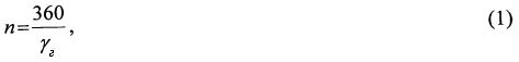
где γг - горизонтальный угол поля зрения в градусах наблюдаемого оператором изображения.where γ g is the horizontal angle of the field of view in degrees observed by the operator of the image.
Недостаток прототипа способа мониторинга - возникновение потерь кругового обзора по параметру угол места при вписывании прямоугольной мишени фотоприемника в кольцевое изображение панорамного объектива.The disadvantage of the prototype of the monitoring method is the occurrence of circular viewing losses in the elevation parameter when a rectangular target of the photodetector is entered into the annular image of a panoramic lens.
Если же для исключения потерь по углу места это кольцевое изображение вписать в прямоугольник мишени, то потребуется матрица ПЗС с увеличенным числом элементов (пикселов). При этом значительная часть пикселов является пассивной (бесполезной), т.к. не несет информации о наблюдаемом сюжете, но принудительно используется при формировании видеосигнала в телевизионной камере.If, to exclude losses in elevation, this ring image is inscribed in the target rectangle, then a CCD matrix with an increased number of elements (pixels) is required. Moreover, a significant part of the pixels is passive (useless), because It does not carry information about the observed plot, but is used forcibly when generating a video signal in a television camera.
Задачей изобретения является сохранение (поддержание неизменным) параметра угол места и исключение пассивных пикселов за счет использования в качестве фотоприемника однострочного кольцевого монохромного сенсора или «малострочного» кольцевого цветного сенсора путем его механического сканирования в перпендикулярном направлении относительно неподвижной плоскости изображения панорамного объектива.The objective of the invention is the preservation (maintenance of unchanged) of the parameter, the elevation angle and the exclusion of passive pixels by using as a photodetector a single-line ring monochrome sensor or "low-line" ring color sensor by mechanical scanning in the perpendicular direction relative to the stationary image plane of the panoramic lens.
Поставленная задача решается тем, что в заявляемом способе панорамного телевизионно-компьютерного мониторинга по варианту 1 устанавливают телевизионную камеру в фиксированное положение, выполняют захват изображения в телевизионной камере панорамным объективом с угловым полем 360 градусов по азимуту, формируют в телевизионной камере аналоговый сигнал изображения наблюдаемого пространства, преобразуют аналоговый видеосигнал в цифровой видеосигнал, передают видеосигнал кольцевого панорамного изображения наблюдаемого пространства по интерфейсу в сервер, записывают цифровой видеосигнал в оперативную память сервера, осуществляют селективный контроль хранящегося в памяти сервера панорамного изображения на экранах видеомониторов двух и более подключенных к серверу персональных компьютеров путем преобразования в сервере панорамного телевизионного изображения в обычное изображение, причем один текущий «кольцевой» кадр считывают из памяти сервера при помощи n «прямоугольных» кадров, число которых удовлетворяет соотношению (1), согласно предполагаемому изобретению для предоставления операторам компьютеров монохромного (черно-белого) изображения формирование аналогового видеосигнала в телевизионной камере выполняют при помощи изготовленного по технологии приборов с зарядовой связью (ПЗС) фотоприемника, имеющего форму кольца и содержащего на общем кристалле «кольцевую» однострочную фотоприемную область, «кольцевой» выходной регистр и преобразователь заряд-напряжение», при этом сам сенсор механически сканируют по кадру в перпендикулярном направлении относительно неподвижной плоскости изображения панорамного объектива, в пределах его углового поля по месту и с шагом, равным ширине фотоприемной строки, причем внешний диаметр фотоприемной области сенсора равен диаметру изображения на выходе панорамного объектива.The problem is solved in that in the inventive method of panoramic television-computer monitoring according to embodiment 1, the television camera is installed in a fixed position, the image is captured in the television camera with a panoramic lens with an angular field of 360 degrees in azimuth, an analog image signal of the observed space is formed in the television camera, convert the analog video signal into a digital video signal, transmit the video signal of the panoramic panoramic image of the observed space interface to the server, record the digital video signal into the server’s RAM, selectively monitor the panoramic image stored in the server’s memory on the screens of two or more personal computers connected to the server by converting the panoramic television image into a regular image in the server, with one current “ring” frame read from the server’s memory using n "rectangular" frames, the number of which satisfies the relation (1), according to the alleged invention In order to provide monochrome (black-and-white) images to computer operators, the analog video signal is generated in a television camera using a charge-coupled device (CCD) technology, which has a ring shape and contains a “ring” single-line photo-receiving region, “ring” on a common crystal output register and charge-voltage converter ”, while the sensor itself is mechanically scanned in a frame in the perpendicular direction relative to the fixed plane of the image eniya panoramic lens within its angular field at the place and at a pitch equal to the width of photodetector rows, the outer diameter of the sensor photodetector area equals the diameter of the panoramic image output lens.
Поставленная задача в заявляемом способе панорамного телевизионно-компьютерного мониторинга по варианту 2 устанавливают телевизионную камеру в фиксированное положение, выполняют захват изображения в телевизионной камере панорамным объективом с угловым полем 360 градусов по азимуту, формируют в телевизионной камере аналоговый сигнал изображения наблюдаемого пространства, преобразуют аналоговый видеосигнал в цифровой видеосигнал, передают видеосигнал кольцевого панорамного изображения наблюдаемого пространства по интерфейсу в сервер, записывают цифровой видеосигнал в оперативную память сервера, осуществляют селективный контроль хранящегося в памяти сервера панорамного изображения на экранах видеомониторов двух и более подключенных к серверу персональных компьютеров путем преобразования в сервере панорамного телевизионного изображения в обычное изображение, причем один текущий «кольцевой» кадр считывают из памяти сервера при помощи n «прямоугольных» кадров, число которых удовлетворяет соотношению (1), согласно предлагаемому изобретению для предоставления операторам компьютеров цветного изображения формирование аналогового видеосигнала в телевизионной камере выполняют при помощи изготовленного по технологии ПЗС фотоприемника, имеющего форму кольца и содержащего на общем кристалле «кольцевую» четырехстрочную фотоприемную область, накрытую кольцевыми по форме и последовательно расположенными соответственно инфракрасным (ИК) отсекающим фильтром и мозаичным цветным фильтром, разделяющим свет на голубой, желтый, пурпурный и зеленый компоненты, а также содержащего на общем кристалле «кольцевой» выходной регистр и преобразователь заряд-напряжение», при этом сам сенсор механически сканируют по кадру в перпендикулярном направлении относительно неподвижной плоскости изображения панорамного объектива, в пределах его углового поля по месту и с шагом, равным ширине четырехстрочной фотоприемной области, причем внешний диаметр этой фотоприемной области сенсора равен диаметру изображения на выходе панорамного объектива.The task in the inventive method of panoramic television-computer monitoring according to option 2 set the television camera in a fixed position, perform image capture in the television camera with a panoramic lens with an angular field of 360 degrees in azimuth, form an analog image signal of the observed space in the television camera, convert the analog video signal into digital video signal, transmit the video signal of the circular panoramic image of the observed space via the interface in gray Ver, they record the digital video signal in the server’s RAM, selectively monitor the panoramic image stored in the server’s memory on the screens of two or more personal computers connected to the server by converting the panoramic television image into a regular image in the server, and one current “ring” frame is read from server memory using n "rectangular" frames, the number of which satisfies the relation (1), according to the invention for providing to color image computer operators, the analog video signal is generated in a television camera using a CCD photodetector having a ring shape and containing a “ring” four-line photodetector on a common crystal, covered with a ring shape and sequentially arranged with an infrared (IR) cut-off filter and mosaic a color filter that separates light into cyan, yellow, magenta and green components, as well as containing front "output register and charge-voltage converter", while the sensor itself is mechanically scanned in a frame perpendicular to the fixed plane of the image of the panoramic lens, within its angular field in place and with a step equal to the width of the four-line photo-receiving region, the outer diameter of this the photodetector area of the sensor is equal to the diameter of the image at the output of the panoramic lens.
Сопоставительный анализ с прототипом показывает, что заявляемый способ отличается наличием новых признаков, а именно наличием следующего действия - механического сканирования фотоприемника по кадру в перпендикулярном направлении относительно выходного окна панорамного объектива в пределах его угла места; условием проведения этого действия, заключающимся в выборе величины шага сканирования; а также используемом при этом материальном средстве - фотоприемнике на ПЗС, имеющем не прямоугольную, а кольцевую форму реализации.Comparative analysis with the prototype shows that the inventive method is distinguished by the presence of new features, namely the presence of the following action - mechanical scanning of the photodetector in a frame in the perpendicular direction relative to the output window of the panoramic lens within its elevation angle; the condition for carrying out this action, which consists in choosing the magnitude of the scanning step; and also used with this material means - a photodetector on a CCD having not a rectangular, but a circular form of implementation.
Совокупность известных и новых признаков не известна из уровня техники, поэтому заявляемый способ отвечает требованию новизны.The combination of known and new features is not known from the prior art, therefore, the claimed method meets the requirement of novelty.
В заявляемом решении сканирование по кадру осуществляется по воображаемой цилиндрической поверхности, благодаря чему регистрируется большая площадь оптического пространства, а следовательно, формируется и новая (дополнительная) видеоинформация.In the claimed solution, scanning by frame is carried out on an imaginary cylindrical surface, due to which a large area of the optical space is recorded, and therefore, new (additional) video information is also formed.
Поэтому предлагаемое техническое решение соответствует критерию о наличии изобретательского уровня.Therefore, the proposed solution meets the criterion of the presence of an inventive step.
На фиг. 1 приведена структурная схема устройства, реализующего заявляемый способ; на фиг. 2 - схемотехническая организация монохромного фотоприемника телевизионной камеры; на фиг. 3 - схемотехническая организация цветного фотоприемника телевизионной камеры; на фиг. 4 показан фрагмент цветного фотоприемника, иллюстрирующий подробности его конструкции; на фиг. 5, по данным [2], представлена фотография изображения, полученного при помощи отечественного панорамного зеркально-линзового объектива; на фиг. 6 - иллюстрация геометрических соотношений для мишени фотоприемника, имеющей «прямоугольную» и «кольцевую» форму; на фиг. 7 - предлагаемое оператору панорамное изображение в виде последовательности из 6-ти «прямоугольных» кадров.In FIG. 1 shows a structural diagram of a device that implements the inventive method; in FIG. 2 - circuit design organization of a monochrome photodetector of a television camera; in FIG. 3 - circuit design organization of a color photodetector of a television camera; in FIG. 4 is a fragment of a color photodetector illustrating details of its construction; in FIG. 5, according to [2], a photograph of an image obtained using a domestic panoramic mirror-lens lens is presented; in FIG. 6 is an illustration of geometric relationships for a photodetector target having a “rectangular” and “ring” shape; in FIG. 7 - a panoramic image proposed to the operator in the form of a sequence of 6 “rectangular” frames.
Устройство системы телевизионно-компьютерного мониторинга, в котором реализован заявляемый способ, см. фиг. 1, содержит последовательно соединенные телевизионную камеру 1 и сервер 2, являющийся узлом локальной вычислительной сети, к которому подключены два или более персональных компьютеров в позиции 3, при этом телевизионная камера 1 содержит последовательно расположенные и оптически связанные панорамный объектив 1-1 и фотоприемник 1-2 монохромного или цветного изображения, изготовленный по технологии ПЗС, причем на кристалле монохромного сенсора, см. фиг. 2, расположены «кольцевая» однострочная фотоприемная область 1-2-1, «кольцевой» регистр 1-2-2 и преобразователь «заряд-напряжение» (БПЗН) 1-2-3, а на кристалле цветного сенсора, см. фиг. 3, - то же самое, за исключением фотоприемной области 1-2-1, которая становится четырехстрочной, а также имеет «двухслойное» оптическое покрытие в виде совокупности ИК-фильтра 1-7 и мозаичного цветного фильтра, см. его фрагмент на фиг. 4; в составе телевизионной камеры 1 блок 1-3 механического сканирования сенсора кинематически связан с фотоприемником 1-2 и осуществляет его механическое сканирование по кадру, в пределах угла места панорамного объектива 1-1 и в перпендикулярном направлении относительно неподвижной плоскости его выходного окна, при этом управляющие входы области 1-2-1 сенсора подключены к первому выходу блока 1-4 «кольцевой» развертки видеосигнала, второй выход которого подключен к управляющим входам «кольцевого» регистра 1-2-2 сенсора, третий выход блока 1-4 «кольцевой» развертки - к входу синхронизации сигнального процессора 1-5, четвертый выход блока 1-4 «кольцевой» развертки - к тактовому входу аналого-цифрового преобразователя (АЦП) 1-6, пятый выход блока 1-4 «кольцевой» развертки - к входу синхронизации блока 1-3 механического сканирования сенсора, а управляющий вход блока 1-4 «кольцевой» развертки - к выходу управления экспозицией сигнального процессора 1-5; выход АЦП 1-6 является выходом телевизионной камеры 1; в разъем расширения на материнской плате сервера 2 установлена плата видео, согласованная по каналам ввода/вывода, управлению и питанию с шиной сервера, содержащая блок преобразования «кольцевого» кадра в «прямоугольные» кадры (БПКП), вход которого подключен к выходу блока оперативной памяти на кадр, а выход - к выходу «сеть».A device for a television-computer monitoring system in which the inventive method is implemented, see FIG. 1, comprises a television camera 1 and a server 2 connected in series to a local area network, to which two or more personal computers are connected at position 3, the television camera 1 comprising a series-aligned and optically connected panoramic lens 1-1 and a photodetector 1- 2 of a monochrome or color image manufactured using CCD technology, moreover, on a crystal of a monochrome sensor, see FIG. 2, there is a “ring” single-line photodetector region 1-2-1, a “ring” register 1-2-2 and a charge-voltage converter (BPS) 1-2-3, and on a color sensor chip, see FIG. 3 is the same, with the exception of the photodetector region 1-2-1, which becomes four-line, and also has a “two-layer” optical coating in the form of a combination of an IR filter 1-7 and a mosaic color filter, see its fragment in FIG. four; in the composition of the television camera 1, the mechanical scanning unit 1-3 of the sensor is kinematically connected with the photodetector 1-2 and carries out its mechanical scanning in the frame, within the elevation angle of the panoramic lens 1-1 and in the perpendicular direction relative to the fixed plane of its output window, while controlling the inputs of the 1-2-1 area of the sensor are connected to the first output of the 1-4 block of the “ring” scan of the video signal, the second output of which is connected to the control inputs of the “ring” register 1-2-2 of the sensor, the third output of the block 1-4 "count front ”sweep - to the synchronization input of the signal processor 1-5, the fourth output of block 1-4“ ring ”sweep - to the clock input of an analog-to-digital converter (ADC) 1-6, the fifth output of block 1-4“ ring ”sweep - to the synchronization input of block 1-3 of the mechanical scanning of the sensor, and the control input of block 1-4 of the "circular" scan to the output of the exposure control of the signal processor 1-5; the output of the ADC 1-6 is the output of the television camera 1; a video card is installed in the expansion slot on the server 2 motherboard, matched via the I / O channels, control and power supply with the server bus, containing a block for converting a “ring” frame into “rectangular” frames (BPKP), the input of which is connected to the output of the RAM block per frame, and the output - to the output of the "network".
В зависимости от варианта предлагаемого способа телевизионно-компьютерного мониторинга монохромный фотоприемник реализует однострочную «кольцевую» развертку, а цветной фотоприемник - четырехстрочную «кольцевую» развертку зарядового изображения на фотоприемной области 1-2-1 с последующим поэлементным считыванием зарядов в «кольцевом» регистре 1-2-2 с целью формирования на выходе БПЗН 1-2-3 напряжения видеосигнала в аналоговой форме.Depending on the variant of the proposed method of television-computer monitoring, a monochrome photodetector implements a single-line “ring” scan, and a color photodetector implements a four-line “ring” scan of a charge image on a photodetector region 1-2-1 with subsequent element-wise reading of charges in a “ring” register 1- 2-2 in order to form the voltage of the video signal in analog form at the output of the BPSN 1-2-3.
При этом в течение одного интервала происходит процесс накопления зарядовых пакетов пропорционально освещенности панорамного сюжета в светочувствительных пикселах фотоприемной области 1-2-1. В течение кратковременного промежутка последующего интервала открывается фотозатвор, и заряды всех «кольцевых» строк, участвовавших в накоплении, переносятся (за один шаг поворота) в экранированные от света пикселы, расположенные на той же области 1-2-1.In this case, during one interval, the process of accumulation of charge packets occurs in proportion to the illumination of the panoramic plot in the photosensitive pixels of the photodetector region 1-2-1. During a short period of the subsequent interval, a photo shutter opens, and the charges of all the “ring” lines involved in the accumulation are transferred (in one rotation step) to the screened from light pixels located in the same region 1-2-1.
Затем фотозатвор закрывается и в новом цикле на мишени выполняется накопление другой зарядовой «картины», а накопленные в предыдущем цикле зарядовые пакеты в радиальных направлениях переносятся на периферию кристалла фотоприемника, загружая в промежуточных интервалах новыми зарядами «кольцевой» регистр 1-2-2.Then the photo shutter closes and, in a new cycle, another charge “picture” is accumulated on the target, and the charge packets accumulated in the previous cycle are transferred in radial directions to the periphery of the photodetector crystal, loading the “ring” register 1-2-2 in intermediate intervals with new charges.
Фотоприемник является единственным сенсором видеосигнала цветного изображения, в котором, благодаря применению цветного «кольцевого» фильтра, пикселы ПЗС становятся чувствительными к голубой (Cy), желтой (Ye), пурпурной (Mg) и зеленой (G) цветовым составляющим. Конструкция этого фотоприемника представлена на фиг. 4.The photodetector is the only color image video sensor in which, thanks to the use of a color ring filter, CCD pixels become sensitive to cyan (Cy), yellow (Ye), magenta (Mg) and green (G) color components. The design of this photodetector is shown in FIG. four.
Добавим, что со стороны объектива перед мозаичным фильтром располагается отсекающий ИК-фильтр (см. позицию 1-7 на фиг. 1), который изменяет спектральную характеристику сенсора, обеспечивая ее согласование со спектральной чувствительностью человеческого глаза.We add that on the lens side in front of the mosaic filter there is a cut-off IR filter (see position 1-7 in Fig. 1), which changes the spectral characteristic of the sensor, ensuring its matching with the spectral sensitivity of the human eye.
Здесь используется известный принцип цветного телевидения, утверждающий, что для успешного восстановления цвета, помимо сигнала яркости (Y), достаточно всего двух дополнительных сигналов. Имеются в виду сигнал цветовой разности красного (R-Y) и сигнал цветовой разности синего (В-Y).It uses the well-known principle of color television, which states that for successful color recovery, in addition to the brightness signal (Y), just two additional signals are enough. This refers to the red color difference signal (R-Y) and the blue color difference signal (B-Y).
Отметим, что именно этот принцип реализован в конструкции мозаичного фильтра для фотоприемника в широко распространенных цветных одноматричных телевизионных камерах, см., например [3, с. 155].Note that it is this principle that is implemented in the design of a mosaic filter for a photodetector in widespread color single-matrix television cameras, see, for example, [3, p. 155].
Аналогично режиму, применяемому в одноматричных цветных камерах, здесь перед считыванием в «кольцевом» регистре 1-2-2 зарядовые пакеты соседних (в радиальном направлении) пикселов фотомишени объединяются попарно, причем по-разному для последовательно считываемых первой (нечетной) и второй (четной) «кольцевых» строк формируемого изображения, как показано на фиг. 4.Similar to the mode used in single-matrix color cameras, here, before reading in the “ring” register 1-2-2, the charge packets of neighboring (in the radial direction) photo-target pixels are combined in pairs, and differently for the first (odd) and second (even) sequentially read ) “Circular” lines of the generated image, as shown in FIG. four.
Первая строка содержит попарные отсчеты: (Mg+Cy), (G+Ye), (Mg+Cy), (G+Ye) и так далее.The first line contains pairwise samples: (M g + C y ), (G + Y e ), (M g + C y ), (G + Y e ) and so on.
Вторая строка: попарные отсчеты: (Cy+G), (Ye+Mg), (Cy+G), (Ye+Mg) и так далее.Second line: pairwise samples: (C y + G), (Y e + M g ), (C y + G), (Y e + M g ) and so on.
Для получения яркостного сигнала для нечетной строки производится операция по аналогичному в [3, с. 155] алгоритму, который заключается в том, что выполняется задержка по времени на элемент разложения «кольцевого» поворота и суммирование попарных отсчетов:To obtain a luminance signal for an odd line, an operation is performed similar to that in [3, p. 155] the algorithm, which consists in the fact that a time delay is performed on the decomposition element of the "circular" rotation and the summation of pairwise samples:
![]()
![]()
Коэффициент ![]()
![]()
Очевидно, что выражение (2) можно представить так:Obviously, expression (2) can be represented as follows:
![]()
![]()
Применив аналогичный алгоритм для четной строки, получим следующее выражение для яркостного сигнала:Applying a similar algorithm for an even line, we obtain the following expression for the luminance signal:
![]()
![]()
Аналогично представим выражение (3) в основных цветах:Similarly, we represent the expression (3) in primary colors:
![]()
![]()
Для получения цветоразностного сигнала синего (В-Y) выполняется операция по другому алгоритму, который заключается в том, что для нечетной строки выполняется задержка по времени на элемент разложения и вычитание попарных отсчетов:To obtain the color difference signal blue (B-Y), an operation is performed according to another algorithm, which consists in the fact that for an odd line, a time delay is performed on the decomposition element and subtraction of pairwise samples:
![]()
![]()
Для получения цветоразностного сигнала красного (R-Y) выполняется операция по алгоритму, аналогичному при получении цветоразностного сигнала синего, но применительно для четной строки:To obtain the color difference signal red (R-Y), the operation is performed according to an algorithm similar to the receipt of the color difference signal blue, but as applied to an even line:
![]()
![]()
Эти два цветоразностных сигнала совместно с сигналом яркости замешиваются в сигнал CVBS в системе PAL точно так же, как это выполняется в одноматричных цветных телевизионных камерах с мозаичным фильтром. Поясним, что CVBS - аббревиатура от английских слов: «composite video bar signal», т.е. полный видеосигнал.These two color difference signals, together with the luminance signal, are mixed into the CVBS signal in the PAL system in the same way as in single-matrix color television cameras with a mosaic filter. Let us explain that CVBS is an abbreviation of English words: “composite video bar signal”, i.e. full video signal.
Важно отметить, что длина внешней окружности «кольцевого» фотоприемника, как монохромного, так и цветного, у которого внешний радиус R (см. фиг. 6), а мишень вписана в вертикальный размер матрицы ПЗС с форматом: l/h=4/3, превосходит размер по горизонтали для «прямоугольного» сенсора на величину, равную 3/4×π.It is important to note that the length of the outer circumference of the “ring” photodetector, both monochrome and color, with an outer radius R (see Fig. 6) and the target inscribed in the vertical size of the CCD with the format: l / h = 4/3 , exceeds the horizontal size for the "rectangular" sensor by an amount equal to 3/4 × π.
Это означает, что при одинаковой величине площади пиксела выигрыш в их количестве составляет показатель, который не менее 2,5 раз.This means that with the same pixel area, the gain in their number is an indicator that is at least 2.5 times.
Панорамный объектив 1-1 телевизионной камеры, как и в прототипе, предназначен для формирования оптического изображения кругового обзора (кольцевого изображения). В качестве технического решения для панорамного объектива 1-1, совпадающего с аналогичным решением для прототипа, может быть предложен панорамный зеркально-линзовый объектив, конструкция которого запатентована в России отечественными специалистами из Московского государственного университета геодезии и картографии [2].The panoramic lens 1-1 of the television camera, as in the prototype, is designed to form an optical image of a circular view (ring image). As a technical solution for a panoramic lens 1-1, which coincides with a similar solution for the prototype, a panoramic mirror-lens lens can be proposed, the design of which is patented in Russia by Russian specialists from Moscow State University of Geodesy and Cartography [2].
Фотография кольцевого изображения, формируемого панорамным объективом, представлена на фиг. 5. Угловое поле для этого объектива составляет 360 градусов по азимуту и может достигать (75-80) градусов по углу места.A photograph of the annular image formed by the panoramic lens is shown in FIG. 5. The angular field for this lens is 360 degrees in azimuth and can reach (75-80) degrees in elevation.
Наличие пассивной (неинформативной) области в центре оптического кадра панорамного объектива подтверждает целесообразность выбора фотоприемника в пользу кругового кольца.The presence of a passive (non-informative) region in the center of the optical frame of the panoramic lens confirms the advisability of choosing a photodetector in favor of a circular ring.
Блок 1-4 «кольцевой» развертки видеосигнала, сигнальный процессор 1-5 и АЦП 1-6 целесообразно выполнить с использованием комплекта специализированных микросхем высокого уровня интеграции, в т.ч. и программируемого комплекта, предназначенного для обслуживания цветных матриц ПЗС.Block 1-4 of the "circular" scan of the video signal, the signal processor 1-5 and the ADC 1-6, it is advisable to perform using a set of specialized microcircuits with a high level of integration, including and a programmable kit designed to service CCD color matrices.
Блок 1-3 механического сканирования сенсора предназначен для выполнения сканирования по кадру фотоприемника 1-2. Пошаговое перемещение фотоприемника должно соответствовать ширине одной «кольцевой» строки для монохромного сенсора и соответственно четырех «кольцевых» строк для его цветного варианта. По физике работы такое перемещение является электромеханическим.Block 1-3 mechanical scanning of the sensor is designed to perform scanning on the frame of the photodetector 1-2. The step-by-step movement of the photodetector should correspond to the width of one “ring” line for a monochrome sensor and, accordingly, four “ring” lines for its color version. In physics of work, such a movement is electromechanical.
Важно отметить, что для исключения возникновения вертикального смаза формируемого изображения временной промежуток шагового перемещения фотоприемника должен быть достаточно малым относительно интервала накопления зарядов на фотомишени.It is important to note that in order to exclude the occurrence of a vertical blur of the generated image, the time interval of the step-by-step movement of the photodetector should be sufficiently small relative to the interval of charge accumulation on the target.
Способ панорамного телевизионно-компьютерного мониторинга (варианты) осуществляется следующим образом.The method of panoramic television-computer monitoring (options) is as follows.
Телевизионная камера 1 размещается на штативе (на фиг. 1 он не показан).The television camera 1 is placed on a tripod (in Fig. 1 it is not shown).
Панорамный объектив 1-1 формирует «кольцевое» оптическое контролируемой сцены, проецируя его на мишень 1-2-1 фотоприемника телевизионной камеры. Фотоприемник 1-2 реализует «кольцевую» однострочную или четырехстрочную развертку зарядового изображения на фотоприемной области 1-2-1 с последующим поэлементным считыванием зарядовых пакетов в «кольцевом» регистре 1-2-2 и формированием на выходе БПЗН 1-2-3 напряжения видеосигнала в аналоговой форме.The panoramic lens 1-1 forms an “annular” optical of the controlled scene, projecting it onto the target 1-2-1 of the photodetector of the television camera. Photodetector 1-2 implements a “ring” single-line or four-line scan of the charge image in the photodetector region 1-2-1, followed by element-wise reading of the charge packets in the “ring” register 1-2-2 and generating a video signal voltage at the output of the BPSN 1-2-3 in analog form.
В результате последующего аналого-цифрового преобразования видеосигнала на выходе телевизионной камеры 1 формируется цифровой телевизионный сигнал черно-белого или цветного изображения для одной «кольцевой» строки реконструируемого растра. По интерфейсу (например, USB 2,0) в оперативную память сервера 2 будет транслироваться цифровой видеосигнал этой «кольцевой» строки фотоприемника 1-2 при пошаговом перемещении самого фотоприемника на ширину четырех строк его мишени.As a result of the subsequent analog-to-digital conversion of the video signal at the output of the television camera 1, a digital television signal of black and white or color image is generated for one “ring” line of the reconstructed raster. Via the interface (for example, USB 2.0), the digital video signal of this “ring” line of the photodetector 1-2 will be transmitted to the RAM of server 2 when the photodetector itself is moved stepwise to the width of four lines of its target.
В итоге в оперативную память сервера 2 будет занесена видеоинформация о «кольцевом» кадре, полученном при помощи «сканерной» записи составляющих его «кольцевых» строк.As a result, video information about the “circular” frame obtained using the “scanner” recording of the “circular” lines constituting it will be recorded in the RAM of server 2.
Допустим, что, как и в прототипе, горизонтальный угол поля зрения (γг) предъявляемого панорамного изображения составляет 60 градусов.Suppose that, as in the prototype, the horizontal angle of the field of view (γ g ) of the presented panoramic image is 60 degrees.
Тогда должно быть предусмотрено, что одна шестая часть каждой «кольцевой» строки из «кольцевого» кадра записывается в сервере 2 соответственно в один из шести массивов оперативной памяти на кадр.Then it should be provided that one sixth of each "ring" line from the "ring" frame is recorded in server 2, respectively, in one of the six arrays of RAM per frame.
Предположим, что полное число «кольцевых» строк в «кольцевом» кадре составляет m. Необходимость разнесения во времени процесса накопления зарядов в фотоприемнике и процесса шагового перемещения сенсора определяет режим формирования «кольцевого» кадра как медленный, т.е. малокадровый.Suppose that the total number of “ring” lines in a “ring” frame is m. The need for time diversity of the process of accumulation of charges in the photodetector and the process of stepwise movement of the sensor determines the mode of formation of the "ring" frame as slow, i.e. small frame.
Поэтому требуемое время записи всех m строк в сервере 2 составит несколько секунд и, возможно, даже более высокую величину, но это вполне оправдано достигаемым результатом - поддержанием неизменного показателя угла места кругового обзора и оптимизацией фотоприемника для ведения такого обзора.Therefore, the required recording time of all m lines in server 2 will amount to several seconds and, possibly, even a higher value, but this is completely justified by the achieved result - maintaining a constant indicator of the elevation angle of the circular view and optimizing the photodetector for such a review.
Далее, как и в прототипе, в сервере 2 при помощи элемента БПКП, реализующего возложенные на него функции программным путем, осуществляется операция считывания видеосигнала, а в результате - конвертирование «кольцевого» кадра в обычные «прямоугольные» кадры вещательного телевидения и возможность предоставления этой информации на выходе «сеть» сервера 2.Further, as in the prototype, in server 2, using the BPC element that implements the functions assigned to it programmatically, the video signal is read, and as a result, the “ring” frame is converted into ordinary “rectangular” frames of broadcast television and the ability to provide this information at the output of the "network" server 2.
Следовательно, цифровой видеосигнал записи для каждого «кольцевого» кадра изображения преобразуется в 6 «прямоугольных» кадров, которые могут быть предложены в виде выбранной последовательности (см. фиг. 7) операторам компьютеров 3.Therefore, the digital video recording signal for each "ring" image frame is converted into 6 "rectangular" frames, which can be offered in the form of a selected sequence (see Fig. 7) to computer operators 3.
Отметим, что операция считывания «прямоугольных» кадров включает и коррекцию геометрических искажений соответствующего участка панорамного изображения аналогично тому, как это реализуется в прототипе.Note that the operation of reading the "rectangular" frames includes the correction of geometric distortions of the corresponding section of the panoramic image in the same way as it is implemented in the prototype.
В настоящее время все элементы структурной схемы устройства панорамного телевизионно-компьютерного мониторинга освоены или могут быть освоены отечественной промышленностью.Currently, all elements of the structural diagram of a panoramic television-computer monitoring device are mastered or can be mastered by domestic industry.
Поэтому следует считать предлагаемое изобретение на способ панорамного телевизионно-компьютерного мониторинга (варианты) соответствующим требованию о промышленной применимости.Therefore, we should consider the present invention as a method of panoramic television-computer monitoring (options) corresponding to the requirement of industrial applicability.
ИСТОЧНИКИ ИНФОРМАЦИИINFORMATION SOURCES
1. Патент РФ №2371880, МПК H04N 7/00. Способ панорамного телевизионного наблюдения и устройство для его осуществления / В.М. Смелков // Б.И. - 2009. - №30.1. RF patent No. 2371880, IPC H04N 7/00. The method of panoramic television surveillance and device for its implementation / V.M. Smelkov // B.I. - 2009. - No. 30.
2. Патент РФ №2185645, МПК G02B 13/06, G02B 17/08. Панорамный зеркально-линзовый объектив / А.В. Куртов, В.А. Соломатин // Б.И. - 2002. - №20.2. RF patent No. 2185645, IPC G02B 13/06, G02B 17/08. Panoramic mirror-lens / A.V. Kurtov, V.A. Solomatin // B.I. - 2002. - No. 20.
3. Владо Дамьяновски. CTV. Библия видеонаблюдения, Цифровые и сетевые технологии / Перевод с англ. М.: ООО «Ай-Эс-Эс Пресс», 2006.3. Vlado Damianowski. CTV. Bible CCTV, Digital and Network Technology / Translated from English. M .: LLC "IS-ES Press", 2006.
Claims (2)
где γг - горизонтальный угол поля зрения в градусах наблюдаемого оператором изображения, отличающийся тем, что для предоставления операторам компьютеров монохромного (черно-белого) изображения формирование аналогового видеосигнала в телевизионной камере выполняют при помощи изготовленного по технологии приборов с зарядовой связью (ПЗС) фотоприемника, имеющего форму кольца и содержащего на общем кристалле «кольцевую» однострочную фотоприемную область, «кольцевой» выходной регистр и преобразователь «заряд-напряжение», при этом сам сенсор механически сканируют по кадру в перпендикулярном направлении относительно неподвижной плоскости изображения панорамного объектива, в пределах его углового поля по месту и с шагом, равным ширине фотоприемной строки, причем внешний диаметр фотоприемной области сенсора равен диаметру изображения на выходе панорамного объектива. 1. The method of panoramic television-computer monitoring (options) according to option 1, which consists in installing the television camera in a fixed position, capturing the image in the television camera with a panoramic lens with an angular field of 360 degrees in azimuth, generating an analog image signal in the television camera of the observed space, convert the analog video signal into a digital video signal, transmit the video signal of the panoramic panoramic image of the observed space via the interface in server, record the digital video signal in the server’s RAM, selectively monitor the panoramic image stored in the server’s memory on the screens of two or more personal computers connected to the server by converting the panoramic television image into a regular image in the server, and one current “ring” frame is read from server memory using n "rectangular" frames, the number of which satisfies the ratio:
where γ g is the horizontal angle of the field of view in degrees of the image observed by the operator, characterized in that for providing the computer operators with a monochrome (black and white) image, the formation of the analog video signal in the television camera is performed using a charge-coupled device (CCD) made by the technology of the photodetector, having a ring shape and containing a “ring” single-line photodetector region, a “ring” output register and a charge-voltage converter on a common crystal, The sensor is mechanically scanned in a frame perpendicular to the fixed image plane of the panoramic lens, within its angular field in place and with a step equal to the width of the photodetector line, and the outer diameter of the photodetector region of the sensor is equal to the diameter of the image at the output of the panoramic lens.
Priority Applications (1)
| Application Number | Priority Date | Filing Date | Title |
|---|---|---|---|
| RU2015118475/07A RU2578194C1 (en) | 2015-05-18 | 2015-05-18 | Method for panoramic television-computer monitoring (versions) |
Applications Claiming Priority (1)
| Application Number | Priority Date | Filing Date | Title |
|---|---|---|---|
| RU2015118475/07A RU2578194C1 (en) | 2015-05-18 | 2015-05-18 | Method for panoramic television-computer monitoring (versions) |
Publications (1)
| Publication Number | Publication Date |
|---|---|
| RU2578194C1 true RU2578194C1 (en) | 2016-03-27 |
Family
ID=55656528
Family Applications (1)
| Application Number | Title | Priority Date | Filing Date |
|---|---|---|---|
| RU2015118475/07A RU2578194C1 (en) | 2015-05-18 | 2015-05-18 | Method for panoramic television-computer monitoring (versions) |
Country Status (1)
| Country | Link |
|---|---|
| RU (1) | RU2578194C1 (en) |
Citations (5)
| Publication number | Priority date | Publication date | Assignee | Title |
|---|---|---|---|---|
| SU610317A1 (en) * | 1974-04-29 | 1978-06-05 | Государственный Научно-Исследовательский Институт Машиноведения | Optical-mechanical device for line-by-line two-coordinate scanning |
| US7259788B1 (en) * | 2002-01-28 | 2007-08-21 | Pixim, Inc. | Image sensor and method for implementing optical summing using selectively transmissive filters |
| US7532237B2 (en) * | 2004-07-28 | 2009-05-12 | Panasonic Corporation | Monitor camera device, control method for monitor camera device, and program for monitor camera device |
| RU2371880C1 (en) * | 2008-04-04 | 2009-10-27 | Вячеслав Михайлович Смелков | Panoramic video surveillance method and device for implementing thereof |
| US7768566B2 (en) * | 2000-06-14 | 2010-08-03 | David A Monroe | Dual-mode camera |
-
2015
- 2015-05-18 RU RU2015118475/07A patent/RU2578194C1/en active
Patent Citations (5)
| Publication number | Priority date | Publication date | Assignee | Title |
|---|---|---|---|---|
| SU610317A1 (en) * | 1974-04-29 | 1978-06-05 | Государственный Научно-Исследовательский Институт Машиноведения | Optical-mechanical device for line-by-line two-coordinate scanning |
| US7768566B2 (en) * | 2000-06-14 | 2010-08-03 | David A Monroe | Dual-mode camera |
| US7259788B1 (en) * | 2002-01-28 | 2007-08-21 | Pixim, Inc. | Image sensor and method for implementing optical summing using selectively transmissive filters |
| US7532237B2 (en) * | 2004-07-28 | 2009-05-12 | Panasonic Corporation | Monitor camera device, control method for monitor camera device, and program for monitor camera device |
| RU2371880C1 (en) * | 2008-04-04 | 2009-10-27 | Вячеслав Михайлович Смелков | Panoramic video surveillance method and device for implementing thereof |
Similar Documents
| Publication | Publication Date | Title |
|---|---|---|
| US12289544B2 (en) | Image acquisition method, electronic device, and non-transitory computer-readable storage medium for obtaining a target image with a same resolution as resolution of a pixel array | |
| CN111491111B (en) | High dynamic range image processing system and method, electronic device and readable storage medium | |
| RU2371880C1 (en) | Panoramic video surveillance method and device for implementing thereof | |
| CN111586375B (en) | High dynamic range image processing system and method, electronic device, and readable storage medium | |
| WO2021196553A1 (en) | High-dynamic-range image processing system and method, electronic device and readable storage medium | |
| CN112738493B (en) | Image processing method, image processing apparatus, electronic device, and readable storage medium | |
| CN111741221A (en) | Image acquisition method, camera assembly and mobile terminal | |
| JP2010283743A (en) | Omnidirectional imaging apparatus, panoramic image synthesis method thereof, and panoramic image synthesis program | |
| US12309502B2 (en) | Image processing method, camera assembly and mobile terminal | |
| RU2633758C1 (en) | Hypersensitive television camera for panoramic computer vision system | |
| CN111970460B (en) | High dynamic range image processing system and method, electronic device and readable storage medium | |
| JP6595161B2 (en) | Image processing apparatus, image processing method, and imaging apparatus | |
| US20170085850A1 (en) | Imaging apparatus, imaging method, and program | |
| RU2640756C1 (en) | Computer system device for television circular review of internal surface of large diameter pipes and pipelines | |
| RU2578194C1 (en) | Method for panoramic television-computer monitoring (versions) | |
| RU2579003C1 (en) | Computer system device for panoramic colour image scanning | |
| RU2641287C1 (en) | Television camera of colour image for panoramic computer scanning | |
| RU2710779C1 (en) | Device for "circular" photodetector of color image for panoramic television-computer surveillance | |
| RU2579002C1 (en) | Computer system device for panoramic scanning of monochromatic image | |
| RU2675244C1 (en) | Ring photo-receiver of color image for panoramic television-computer monitoring | |
| CN111970461B (en) | High dynamic range image processing system and method, electronic device and readable storage medium | |
| RU2564678C1 (en) | Computer system for high-sensitivity panoramic video surveillance | |
| RU2641284C1 (en) | Television camera of colour image for panoramic computer observation | |
| RU2570348C1 (en) | Computer system for panoramic colour image television surveillance | |
| RU2564091C1 (en) | Computer system of panoramic tv observation with higher sensitivity at outer periphery of circular image |