RU2513358C2 - Aircraft stabiliser attachment front assembly coupled with expansion joint of two stabiliser side torsion boxes - Google Patents
Aircraft stabiliser attachment front assembly coupled with expansion joint of two stabiliser side torsion boxes Download PDFInfo
- Publication number
- RU2513358C2 RU2513358C2 RU2011121221/11A RU2011121221A RU2513358C2 RU 2513358 C2 RU2513358 C2 RU 2513358C2 RU 2011121221/11 A RU2011121221/11 A RU 2011121221/11A RU 2011121221 A RU2011121221 A RU 2011121221A RU 2513358 C2 RU2513358 C2 RU 2513358C2
- Authority
- RU
- Russia
- Prior art keywords
- front fitting
- stabilizer
- central part
- shear panel
- fitting
- Prior art date
Links
- 239000003381 stabilizer Substances 0.000 title claims abstract description 63
- 239000002131 composite material Substances 0.000 claims abstract description 14
- 238000000034 method Methods 0.000 claims description 9
- 230000008569 process Effects 0.000 claims description 6
- 238000004026 adhesive bonding Methods 0.000 claims description 4
- 230000013011 mating Effects 0.000 claims description 2
- 239000007787 solid Substances 0.000 claims description 2
- 238000012546 transfer Methods 0.000 abstract description 4
- 230000000694 effects Effects 0.000 abstract description 3
- 210000005069 ears Anatomy 0.000 abstract 2
- 230000003247 decreasing effect Effects 0.000 abstract 1
- 239000000126 substance Substances 0.000 abstract 1
- 230000006870 function Effects 0.000 description 6
- 238000004519 manufacturing process Methods 0.000 description 6
- 238000013461 design Methods 0.000 description 5
- 230000021615 conjugation Effects 0.000 description 3
- 238000009826 distribution Methods 0.000 description 3
- 239000000463 material Substances 0.000 description 3
- 239000011347 resin Substances 0.000 description 3
- 229920005989 resin Polymers 0.000 description 3
- 230000008901 benefit Effects 0.000 description 2
- 230000008859 change Effects 0.000 description 2
- 238000007906 compression Methods 0.000 description 2
- 230000008878 coupling Effects 0.000 description 2
- 238000010168 coupling process Methods 0.000 description 2
- 238000005859 coupling reaction Methods 0.000 description 2
- 230000006378 damage Effects 0.000 description 2
- 238000000926 separation method Methods 0.000 description 2
- 238000001721 transfer moulding Methods 0.000 description 2
- 229920000049 Carbon (fiber) Polymers 0.000 description 1
- RTAQQCXQSZGOHL-UHFFFAOYSA-N Titanium Chemical compound [Ti] RTAQQCXQSZGOHL-UHFFFAOYSA-N 0.000 description 1
- 238000005452 bending Methods 0.000 description 1
- 239000004917 carbon fiber Substances 0.000 description 1
- 150000001875 compounds Chemical class 0.000 description 1
- 230000007797 corrosion Effects 0.000 description 1
- 238000005260 corrosion Methods 0.000 description 1
- 239000000835 fiber Substances 0.000 description 1
- 238000009434 installation Methods 0.000 description 1
- 238000012423 maintenance Methods 0.000 description 1
- 229910052751 metal Inorganic materials 0.000 description 1
- 239000002184 metal Substances 0.000 description 1
- VNWKTOKETHGBQD-UHFFFAOYSA-N methane Chemical compound C VNWKTOKETHGBQD-UHFFFAOYSA-N 0.000 description 1
- 230000008447 perception Effects 0.000 description 1
- 238000011160 research Methods 0.000 description 1
- 239000003351 stiffener Substances 0.000 description 1
- 239000010936 titanium Substances 0.000 description 1
- 229910052719 titanium Inorganic materials 0.000 description 1
- 230000004580 weight loss Effects 0.000 description 1
- 239000013585 weight reducing agent Substances 0.000 description 1
Images


Classifications
-
- B—PERFORMING OPERATIONS; TRANSPORTING
- B64—AIRCRAFT; AVIATION; COSMONAUTICS
- B64C—AEROPLANES; HELICOPTERS
- B64C1/00—Fuselages; Constructional features common to fuselages, wings, stabilising surfaces or the like
- B64C1/26—Attaching the wing or tail units or stabilising surfaces
-
- B—PERFORMING OPERATIONS; TRANSPORTING
- B64—AIRCRAFT; AVIATION; COSMONAUTICS
- B64C—AEROPLANES; HELICOPTERS
- B64C5/00—Stabilising surfaces
- B64C5/02—Tailplanes
Landscapes
- Engineering & Computer Science (AREA)
- Aviation & Aerospace Engineering (AREA)
- Mechanical Engineering (AREA)
- Connection Of Plates (AREA)
- Revetment (AREA)
Abstract
Description
Область техники, к которой относится изобретениеFIELD OF THE INVENTION
Настоящее изобретение относится к авиастроению, в частности к конструкции летательных аппаратов, а именно к конструктивному сопряжению переднего фитинга стабилизатора летательного аппарата с соединением двух боковых кессонов стабилизатора.The present invention relates to the aircraft industry, in particular to the design of aircraft, and in particular to the structural coupling of the front fitting of the stabilizer of the aircraft with the connection of the two side caissons of the stabilizer.
В частности, настоящее изобретение относится к конструктивному сопряжению переднего фитинга стабилизатора летательного аппарата с работающим на растяжение соединением двух боковых кессонов стабилизатора.In particular, the present invention relates to the structural conjugation of the front fitting of the stabilizer of an aircraft with a tensile connection of two side caissons of the stabilizer.
Уровень техникиState of the art
Боковые кессоны стабилизатора летательного аппарата являются конструкциями, хорошо известными в авиационной промышленности, и представляют собой основную силовую конструкцию стабилизатора летательного аппарата.The lateral caissons of the aircraft stabilizer are structures well known in the aviation industry and represent the main power structure of the aircraft stabilizer.
Конструктивно кессон состоит из лонжеронов, обычно прямых и расположенных вдоль конструкции, нервюр, расположенных между лонжеронами перпендикулярно им и крепящихся к ним, и обшивки, расположенной таким образом, что она покрывает каркас, образованный лонжеронами и нервюрами, и крепится к нему.Structurally, the caisson consists of spars, usually straight and located along the structure, ribs located between the spars perpendicular to them and attached to them, and a lining located in such a way that it covers the frame formed by the spars and ribs and is attached to it.
Функция лонжеронов состоит в поглощении напряжений, возникающих при изгибе; нервюры распределяют напряжения по лонжеронам и придают форму обшивке, а обшивка передает нервюрам и лонжеронам аэродинамическую нагрузку и силу сопротивления воздуха, которые воздействуют на ее аэродинамическую поверхность. Кроме этого, кессоны обычно содержат элементы жесткости, крепящиеся к внутренней поверхности обшивки и обеспечивающие устойчивость последней к прогибу.The function of the side members is to absorb the stresses arising during bending; the ribs distribute stresses to the side members and shape the skin, and the body transfers the ribs and side members to the aerodynamic load and air resistance, which act on its aerodynamic surface. In addition, the caissons usually contain stiffeners attached to the inner surface of the casing and ensuring the latter's resistance to deflection.
В существующих в настоящее время конструкциях соединения между боковыми кессонами обычно выполняются в виде работающих на сдвиг элементов - панелей либо несколько более сложных деталей, связанных с обшивкой обоих боковых кессонов, причем эти детали располагаются вблизи плоскости симметрии или в самой этой плоскости. В качестве примера таких деталей можно назвать центральную нервюру или передний фитинг. Кроме того, предъявляемые обычно требования к обеспечению узких допусков и высокой прочности означают, что изготовление деталей этого типа сопряжено, как правило, с использованием дорогостоящих и труднообрабатываемых материалов, например титана, что значительно повышает стоимость изготовления и сборки, а также увеличивает вес летательного аппарата.In current designs, the connections between the side caissons are usually made in the form of shear-acting elements - panels or several more complex parts associated with the sheathing of both side caissons, and these parts are located near the plane of symmetry or in this plane itself. An example of such parts is the central rib or front fitting. In addition, usually the requirements for ensuring narrow tolerances and high strength mean that the manufacture of parts of this type involves, as a rule, the use of expensive and difficult to process materials, such as titanium, which significantly increases the cost of manufacture and assembly, and also increases the weight of the aircraft.
Далее, общеизвестно, что авиационная промышленность нуждается в конструкциях, способных выдерживать высокие нагрузки, которым они подвергаются, с соблюдением требований к устойчивости и жесткости, вследствие чего эти конструкции должны быть как можно более легкими и в то же время удовлетворять всем нормам безопасности, установленным руководящими органами в области авиации.Further, it is well known that the aviation industry needs structures that can withstand the high loads to which they are subject, in compliance with the requirements for stability and rigidity, as a result of which these structures should be as light as possible and at the same time meet all safety standards established by the guidelines authorities in the field of aviation.
В связи с этим продолжаются исследования соединений, работающих на растяжение, с целью оценки их потенциальных возможностей в смысле уменьшения веса и затрат на изготовление и сборку и улучшения технических характеристик летательных аппаратов.In this regard, research continues on tensile compounds in order to assess their potential capabilities in terms of reducing weight and manufacturing and assembly costs and improving the technical characteristics of aircraft.
В последние годы для соединения деталей летательных аппаратов разработаны элементы, работающие на растяжение, которые в настоящее время применяются для соединения небольших деталей самолетов. В патенте US 6415496 описана процедура выполнения разъемных и/или неразъемных соединений, работающих на растяжение-сжатие, с применением композиционных материалов.In recent years, tensile elements have been developed to connect parts of aircraft, which are currently used to connect small parts of aircraft. US Pat. No. 6,415,496 describes a procedure for making detachable and / or one-piece tensile-compression joints using composite materials.
Одной из областей применения этого патента является работающий на растяжение элемент соединения двух боковых кессонов стабилизатора летательного аппарата. Тем не менее, для элемента соединения этого типа, работающего на растяжение и предназначенного для установки между двумя боковыми кессонами стабилизатора, необходимо сначала решить проблему, связанную с сопряжением этого соединения, работающего на растяжение, с другими деталями, расположенными в этой зоне.One of the applications of this patent is a tensile element for connecting two side caissons of an aircraft stabilizer. However, for a tensile joint of this type that is intended to be installed between two side caissons of the stabilizer, it is first necessary to solve the problem of pairing this tensile joint with other parts located in this zone.
В число деталей, расположенных в зоне, где реализуется работающее на растяжение соединение между двумя боковыми кессонами стабилизатора, входит передний фитинг - кронштейн, соединяющий переднюю часть центроплана стабилизатора с винтом подъемника, при вращении которого происходит подъем или опускание передней части стабилизатора и, следовательно, его поворот вокруг оси, расположенной в его задней части, в результате чего изменяется угол установки стабилизатора. Другими словами, передний фитинг служит для изменения положения стабилизатора по высоте с обеспечением перестановки стабилизатора в требуемое балансировочное положение.The number of parts located in the area where the tensile joint between the two side stabilizer caissons is realized includes a front fitting - a bracket connecting the front part of the stabilizer center section with the elevator screw, during rotation of which the front part of the stabilizer is raised or lowered and, therefore, it rotation around an axis located in its rear part, as a result of which the angle of installation of the stabilizer changes. In other words, the front fitting serves to change the position of the stabilizer in height to ensure that the stabilizer is moved to the desired balancing position.
Дополнительно к вышесказанному следует отметить, что передний фитинг должен работать как отказоустойчивый элемент, что еще более усложняет процесс конструирования этой зоны.In addition to the above, it should be noted that the front fitting should work as a fault-tolerant element, which further complicates the process of constructing this zone.
Отсюда следует, что, поскольку соединение между двумя боковыми кессонами стабилизатора обычно выполняется в виде работающего на сдвиг элемента, а цель заключается в создании элемента, работающего на растяжение, то необходимо выполнить повторное изучение и проектирование всех деталей, образующих передний узел крепления стабилизатора с работающим на сдвиг соединением боковых кессонов, и существующего переднего фитинга, а также реализовать способ передачи нагрузок на боковые кессоны в соответствии с новыми решениями, чтобы привести все вышеперечисленное в соответствие с новым типом соединения, работающего на растяжение.It follows that, since the connection between the two side stabilizer caissons is usually in the form of a shear-working element, and the goal is to create a tensile element, it is necessary to re-examine and design all the parts that form the front stabilizer mount with working on shear by connecting the side caissons and the existing front fitting, as well as implement a method of transferring loads to the side caissons in accordance with new solutions to bring all the above in accordance with a new type of tensile joint.
Кроме того, еще одним следствием требований, предъявляемых к устойчивости, жесткости и легкости авиационных конструкций, является еще более широкое применение в силовых конструкциях композиционных материалов, которые, будучи использованными надлежащим образом, могут обеспечить весьма значительное снижение веса и уменьшение числа конструктивных элементов по сравнению с металлическими конструкциями.In addition, another consequence of the requirements for stability, rigidity and lightness of aircraft structures is the wider use of composite materials in power structures, which, when used properly, can provide a very significant weight reduction and a decrease in the number of structural elements compared to metal structures.
Другими словами, цель заключается в исследовании структуры, нагрузок и набора элементов, расположенных вокруг работающего на растяжение соединения двух боковых кессонов стабилизатора, чтобы найти более приемлемый путь реализации сопряжения этого соединения с передним фитингом.In other words, the goal is to study the structure, loads and a set of elements located around the tensile joint of the two side stabilizer caissons in order to find a more acceptable way of realizing the coupling of this joint with the front fitting.
В контексте настоящего описания под композиционным материалом следует понимать, главным образом, смолу или пластмассу, армированную волокнами, имеющими различную ориентацию, чем достигается оптимизация механических свойств этого материала.In the context of the present description, a composite material should be understood mainly as a resin or plastic reinforced with fibers having different orientations, thereby optimizing the mechanical properties of this material.
Наряду с преимуществом меньшего веса, такой композиционный материал обладает и преимуществом отсутствия эффектов усталости и коррозии.Along with the advantage of less weight, such a composite material has the advantage of the absence of the effects of fatigue and corrosion.
Раскрытие изобретенияDisclosure of invention
Целью настоящего изобретение является преодоление проблемы, создаваемой сопряжением переднего фитинга и работающего на растяжение соединения двух боковых кессонов стабилизатора летательного аппарата.The aim of the present invention is to overcome the problem created by the conjugation of the front fitting and the tensile joint of the two side caissons of the aircraft stabilizer.
При этом в основу изобретения положена задача создания переднего узла крепления стабилизатора летательного аппарата, который был бы сопрягаем с работающим на растяжение соединением двух боковых кессонов стабилизатора и в котором фитинг сохранял бы свои функции по перестановке переставляемого стабилизатора, а все детали, входящие в узел, можно было бы изготавливать из композиционного материала, с одновременным сведением к минимуму нагрузок, передаваемых боковым кессонам стабилизатора, и с целью улучшения характеристик применительно к усталостным свойствам существующих в настоящее время конструкций, облегчения их технического обслуживания и снижения веса летательного аппарата.At the same time, the invention is based on the task of creating a front attachment point for the stabilizer of the aircraft, which would be interfaced with a tensile connection of two side stabilizer caissons, and in which the fitting would retain its functions of rearranging the interchangeable stabilizer, and all the parts included in the assembly can be It would be made of a composite material, while minimizing the loads transmitted to the side caissons of the stabilizer, and in order to improve the performance in relation to fatigue properties of currently existing structures, facilitating their maintenance and reduce the weight of the aircraft.
Другой задачей настоящего изобретения является также создание такого узла, все детали которого можно было изготавливать из композиционного материала, благодаря чему обеспечивалось бы снижение веса, что является решающим фактором для авиационной промышленности.Another objective of the present invention is also the creation of such a node, all the details of which could be made of composite material, which would ensure weight loss, which is a decisive factor for the aviation industry.
Третьей задачей изобретения является создание компактного переднего фитинга, изготовленного в виде цельной детали из композиционного материала.A third object of the invention is to provide a compact front fitting made in the form of an integral part from a composite material.
Таким образом, объектом настоящего изобретения является передний узел крепления стабилизатора летательного аппарата, сопрягаемый с работающим на растяжение соединением двух боковых кессонов стабилизатора и содержащий:Thus, an object of the present invention is a front attachment point of an aircraft stabilizer, mating with a tensile joint of two side stabilizer caissons and comprising:
- передний фитинг;- front fitting;
- переднюю работающую на сдвиг панель;- front shear panel;
- верхнюю работающую на сдвиг панель;- top shear panel;
- нижнюю работающую на сдвиг панель;- lower shear panel;
- соединительную деталь в виде стойки для присоединения нервюры к лонжерону, соединяющую предлагаемый узел с центральной нервюрой кессона стабилизатора летательного аппарата.- a connecting part in the form of a rack for attaching the ribs to the spar, connecting the proposed site with the Central rib of the caisson of the stabilizer of the aircraft.
Согласно изобретению передний фитинг содержит центральную часть и две боковых части, которые подробнее описаны ниже.According to the invention, the front fitting comprises a central part and two side parts, which are described in more detail below.
Согласно изобретению центральная часть переднего фитинга представляет собой деталь, имеющую прямоугольное основание и форму коробки, у которой длинные боковые стенки расположены вертикально и параллельно друг к другу и симметрично, а короткие верхняя и нижняя стенки являются непараллельными друг другу и несимметричными. Из боковых стенок выступают отдельные проушины, расположенные в одной плоскости с соответствующими боковыми стенками. Каждая из проушин имеет отверстие. Нижняя короткая стенка слегка выгнута и обращена вогнутостью к верхней короткой стенке.According to the invention, the central part of the front fitting is a part having a rectangular base and a box shape, in which the long side walls are arranged vertically and parallel to each other and symmetrically, and the short upper and lower walls are non-parallel to each other and asymmetrical. Separate eyelets protrude from the side walls, located in the same plane with the corresponding side walls. Each of the eyes has a hole. The lower short wall is slightly curved and facing concavity to the upper short wall.
Аналогичным образом, каждая из двух боковых частей переднего фитинга имеет боковую сторону, симметричную каждой из снабженных проушиной длинных боковых стенок центральной части переднего фитинга, если рассматривать боковую стенку в совокупности с ее проушиной и отверстием. Таким образом, каждая симметричная боковая сторона каждой боковой части фитинга копирует контур боковой стенки, проушины и отверстия центральной части фитинга и имеет выступающий край, проходящий вдоль почти всего ее наружного контура за исключением части последнего, соответствующей проушине.Similarly, each of the two side portions of the front fitting has a side symmetrical to each of the long side walls provided with an eyelet of the central portion of the front fitting, when considering the side wall in conjunction with its eye and hole. Thus, each symmetrical side of each side of the fitting copies the contour of the side wall, eyes and holes of the central part of the fitting and has a protruding edge extending along almost its entire outer contour except for the part of the latter corresponding to the eye.
Упомянутые проушины расположены в одной плоскости с боковыми стенками, из которых они выступают.The said eyes are located in the same plane with the side walls from which they protrude.
Передний фитинг может быть сборным из трех своих основных частей (центральной и двух боковых), которые могут быть соединены в процессе его изготовления либо посредством последующего склеивания.The front fitting can be prefabricated from its three main parts (central and two side), which can be connected during its manufacture or by subsequent gluing.
После соединения этих трех основных частей друг с другом полученный фитинг имеет две проушины, каждая из которых представляет собой слоистую пластину, образованную проушиной центральной части и копирующей ее проушиной соответствующей боковой части. Следовательно, путь нагружения увеличивается вдвое. Более того, в случае разрушения одной из двух частей сборной проушины оставшаяся часть будет в состоянии выдержать предельную нагрузку, чем обеспечивается выполнение авиационных требований.After connecting these three main parts with each other, the resulting fitting has two eyes, each of which is a layered plate formed by the eye of the central part and the eye of the corresponding side part copying it. Therefore, the loading path is doubled. Moreover, in the event of the destruction of one of the two parts of the prefabricated eye, the remaining part will be able to withstand the ultimate load, which ensures compliance with aviation requirements.
В альтернативном варианте осуществления настоящего изобретения центральная часть переднего фитинга разделена на две половины.In an alternative embodiment of the present invention, the center portion of the front fitting is divided into two halves.
Согласно изобретению передняя работающая на сдвиг панель имеет две вертикальные линии сгиба, определяющие центральную зону и две боковые зоны. Передняя работающая на сдвиг панель соединяет стенки двух передних лонжеронов, выходящих из соответствующих боковых кессонов стабилизатора, а также воспринимает вертикальную нагрузку от переднего фитинга.According to the invention, the front shear panel has two vertical fold lines defining a central zone and two side zones. The front shear panel connects the walls of the two front side members extending from the respective side stabilizer caissons, and also perceives the vertical load from the front fitting.
Кроме того, в описанном выше альтернативном варианте осуществления изобретения, а именно в том, где центральная часть переднего фитинга разделена на две половины, эта панель также обеспечивает целостность центральной части переднего фитинга.In addition, in the alternative embodiment described above, namely, in which the center portion of the front fitting is divided into two halves, this panel also ensures the integrity of the center portion of the front fitting.
Согласно изобретению соединительная деталь в виде стойки для присоединения нервюры к лонжерону отвечает за соединение узла крепления стабилизатора с центральной нервюрой работающего на растяжение соединения кессонов стабилизатора. Эта соединительная деталь имеет Т-образную форму в поперечном сечении и соединяется с передней работающей на сдвиг панелью в середине ее центральной зоны с помощью процессов совместного отверждения, склеивания или клепки. Ее функция состоит в соединении центральной нервюры стабилизатора летательного аппарата с работающей на сдвиг передней панелью и в передаче вертикальной нагрузки с переднего фитинга на центральную нервюру стабилизатора.According to the invention, a connecting piece in the form of a strut for attaching the ribs to the spar is responsible for connecting the stabilizer mount with the central rib of the tensile connection of the stabilizer caissons. This connecting piece has a T-shape in cross section and is connected to the front shear panel in the middle of its central zone using joint curing, bonding or riveting processes. Its function is to connect the central rib of the stabilizer of the aircraft with the shear front panel and to transfer the vertical load from the front fitting to the central rib of the stabilizer.
Таким образом, благодаря включению в конструкцию передней работающей на сдвиг панели вертикальная нагрузка с переднего фитинга передается в виде поперечной силы на стенки передних лонжеронов боковых кессонов стабилизатора, а посредством соединительной детали в виде стойки для присоединения нервюры к лонжерону - и на центральную нервюру стабилизатора. Кроме этого, передняя работающая на сдвиг панель обеспечивает непрерывность распределения поперечной силы, передаваемой передними лонжеронами боковых кессонов стабилизатора.Thus, due to the inclusion of the front shear panel in the design, the vertical load from the front fitting is transferred in the form of shear force to the walls of the front side members of the stabilizer side caissons, and through the connecting piece in the form of a rack for attaching the ribs to the side member - to the central stabilizer rib. In addition, the front shear panel provides a continuous distribution of the shear force transmitted by the front side members of the stabilizer side caissons.
Согласно изобретению верхняя и нижняя работающие на сдвиг панели имеют такую форму, которая копирует форму или контур переднего фитинга сверху и снизу для соединения с верхней и нижней обшивками, образующими кессон, простираются за пределы области, перекрываемой передним фитингом, в стороны и в направлении задней части стабилизатора. Этим обеспечивается надежное соединение друг с другом верхней и нижней обшивок, образующих кессон. Кроме того, для охвата пространства, занятого центральной нервюрой, верхняя и нижняя работающие на сдвиг панели имеют вырезы.According to the invention, the upper and lower shear panels have a shape that copies the shape or contour of the front fitting above and below for connection with the upper and lower casing forming the caisson, extending outside the area covered by the front fitting, to the sides and towards the rear stabilizer. This ensures a reliable connection with each other of the upper and lower casing, forming a caisson. In addition, to cover the space occupied by the central rib, the upper and lower shear panels have cutouts.
Основная функция верхней и нижней панелей, работающих на сдвиг, состоит в восприятии момента, создаваемого вертикальной нагрузкой, прикладываемой к переднему фитингу. Кроме того, эти панели обеспечивают непрерывность распределения нагрузок растяжения-сжатия, передаваемых с верхней и нижней поясов передних лонжеронов обоих боковых кессонов стабилизатора.The main function of the upper and lower shear panels is to sense the moment created by the vertical load applied to the front fitting. In addition, these panels provide continuous distribution of tensile-compressive loads transmitted from the upper and lower zones of the front side members of both side stabilizer caissons.
Наконец, верхняя и нижняя работающие на сдвиг панели расположены таким образом, что они довершают замыкание боковых кессонов в плоскости соединения, значительно увеличивая их сопротивляемость кручению.Finally, the upper and lower shear panels are arranged in such a way that they complete the closure of the side caissons in the connection plane, significantly increasing their torsion resistance.
Передний фитинг и каждая из дополнительных деталей, образующих описанный выше узел, в предпочтительном варианте изготавливаются из листового материала, содержащего смолу и армированного углеродным волокном, расположенным в плоскости слоистости, которому придается заданная форма с последующим отверждением.The front fitting and each of the additional parts forming the assembly described above are preferably made of sheet material containing a resin and reinforced with carbon fiber located in the layered plane, which is given a given shape with subsequent curing.
Исходя из требований, предъявляемых к допускам, предпочтительным процессом для изготовления этого компонента конструкции является метод трансферного формования (RTM - сокр. от англ. Resin Transfer Molding).Based on the requirements for tolerances, the preferred process for manufacturing this structural component is the transfer molding method (RTM - abbr. From English Resin Transfer Molding).
По соображениям безопасности и надежного крепления компонентов системы внутренние поверхности различных панелей, контактирующие друг с другом, в предпочтительном варианте скрепляются заклепками.For reasons of safety and reliable fastening of system components, the inner surfaces of the various panels in contact with each other are preferably riveted.
Кроме того, одной из целей настоящего изобретения является создание описанного переднего фитинга, изготовленного в виде цельной детали из композиционного материала.In addition, one of the objectives of the present invention is the creation of the described front fitting, made in the form of an integral part from a composite material.
Краткое описание чертежейBrief Description of the Drawings
Для лучшего понимания настоящего описания ниже приведено - только в качестве примера и без ограничения сущности изобретения, - краткое описание приложенных чертежей. На чертежах показано:For a better understanding of the present description below is given - only as an example and without limiting the essence of the invention, a brief description of the attached drawings. The drawings show:
на фиг.1 - вид спереди работающего на растяжение соединения двух боковых кессонов стабилизатора летательного аппарата,figure 1 is a front view of the tensile connection of the two side caissons of the stabilizer of the aircraft,
на фиг.1а и 1б - вид спереди обычного, работающего на сдвиг соединения двух боковых кессонов стабилизатора летательного аппарата (соответственно без переднего фитинга и с передним фитингом),on figa and 1b is a front view of a conventional, working on a shear connection of two side caissons of the stabilizer of the aircraft (respectively, without front fitting and with front fitting),
на фиг.2 - вид в перспективе с пространственным разделением деталей, образующих предлагаемый в изобретении узел,figure 2 is a perspective view with a spatial separation of the parts forming the proposed invention the site,
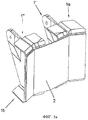
на фиг.3 - вид в перспективе переднего фитинга, соответствующего настоящему изобретению,figure 3 is a perspective view of the front fitting corresponding to the present invention,
на фиг.3а - вид в перспективе с пространственным разделением деталей, представляющих собой компоненты предлагаемого в изобретении переднего фитинга,on figa is a perspective view with a spatial separation of the parts representing the components proposed in the invention of the front fitting,
на фиг.4 - вид в перспективе второго варианта осуществления предлагаемого в изобретении переднего фитинга, центральная часть 1 которого разделена на две половины 1 и 1'',figure 4 is a perspective view of a second embodiment of the proposed invention in the front fitting, the
на фиг.5а - вид в перспективе узла, образованного передним фитингом, соответствующим второму варианту осуществления настоящего изобретения, и работающей на сдвиг передней панелью 2,on figa is a perspective view of the node formed by the front fitting corresponding to the second variant of implementation of the present invention, and working on a shift of the
на фиг.5б - вид в перспективе узла, образованного передним фитингом, соответствующим второму варианту осуществления настоящего изобретения, работающей на сдвиг передней панелью 2 и соединительной деталью 3 в виде стойки для присоединения нервюры к лонжерону; также показаны передние лонжероны 6 двух боковых кессонов,on figb is a perspective view of the node formed by the front fitting corresponding to the second variant of implementation of the present invention, working by shear by the
на фиг.6 - вид сбоку узла, показанного на фиг.5б, с верхней 4 и нижней 5 работающими на сдвиг панелями, причем действующие нагрузки показаны стрелками A и B,in Fig.6 is a side view of the node shown in Fig.5b, with the top 4 and bottom 5 working on shear panels, and the current load is shown by arrows A and B,
на фиг.7 - вид спереди предлагаемого в изобретении узла, сопряженного с работающим на растяжение соединением боковых кессонов 6 стабилизатора, причем стрелками показаны растягивающие и сжимающие нагрузки, передаваемые верхней и нижней работающими на сдвиг панелями с одной стороны боковых кессонов стабилизатора на другую.Fig. 7 is a front view of the assembly of the invention coupled to a tensile connection of the side stabilizer caissons 6, the arrows showing tensile and compressive loads transmitted by the upper and lower shear panels from one side of the stabilizer side caissons to the other.
Осуществление изобретенияThe implementation of the invention
Для более подробного представления цели и сущности настоящего изобретения ниже приведено описание примера его осуществления (не ограничивающего его объема), основанное на чертежах, упомянутых выше.For a more detailed presentation of the purpose and essence of the present invention, the following is a description of an example of its implementation (not limiting its scope), based on the drawings mentioned above.
На фиг.1 показано работающее на растяжение соединение двух боковых кессонов стабилизатора летательного аппарата, тогда как на фиг.1а показано обычное, работающее на сдвиг соединение двух боковых кессонов, а на фиг.1б показано изображенное на фиг.1а работающее на сдвиг соединение в сопряжении с передним фитингом. На чертежах видно, что изменение геометрии этого соединения требует решения проблемы его сопряжения или конструктивной увязки с остальными деталями, расположенными в этой зоне летательного аппарата, например с передним фитингом. Другими словами, необходимо так изменить конструкцию узла, чтобы получить требуемое восприятие нагрузок.Fig. 1 shows a tensile joint of two side caissons of an aircraft stabilizer, while Fig. 1a shows a conventional shear joint of two side caissons, and Fig. 1b shows a shear joint in conjunction with fig. 1a with front fitting. The drawings show that changing the geometry of this connection requires a solution to the problem of its conjugation or structural linking with other parts located in this area of the aircraft, for example, with the front fitting. In other words, it is necessary to change the design of the unit in such a way as to obtain the required perception of the loads.
Следовательно, одной из задач настоящего изобретения является создание узла крепления стабилизатора с требуемыми характеристиками восприятия нагрузок при исключении воздействия этих нагрузок на работающее на растяжение соединение двух боковых кессонов стабилизатора и с обеспечением возможности требуемой перестановки последнего.Therefore, one of the objectives of the present invention is to provide a stabilizer mount assembly with the required load sensing characteristics while eliminating the effect of these loads on the tensile connection of the two side stabilizer caissons and providing the possibility of the required permutation of the latter.
На фиг.2 показаны все детали, образующие предлагаемый в изобретенииFigure 2 shows all the details forming the proposed invention
узел.knot.
Этот узел содержит:This node contains:
- передний фитинг 1, 1а и 1b,-
- работающую на сдвиг переднюю панель 2,-
- работающую на сдвиг верхнюю панель 4,- shear upper panel 4,
- работающую на сдвиг нижнюю панель 5,-
- соединительную деталь 3 в виде стойки для присоединения нервюры к лонжерону, предназначенную для соединения с центральной нервюрой стабилизатора.- a connecting part 3 in the form of a rack for attaching the ribs to the spar, designed to connect with the Central rib of the stabilizer.
Из фиг.3 видно, что передний фитинг состоит из центральной части 1 и двух боковых частей 1а и 1b, которые подробнее описаны ниже.Figure 3 shows that the front fitting consists of a
На фиг.3a показано, что центральная часть 1 переднего фитинга представляет собой деталь, имеющую прямоугольное основание 1j и форму коробки, у которой длинные боковые стенки 1с расположены вертикально, параллельно друг к другу и симметрично, причем из этих боковых стенок 1с выступают отдельные проушины 1f, расположенные с ними в одной плоскости. Каждая проушина 1f имеет отверстие 1g. Короткие верхняя 1d и нижняя 1е стенки центральной части 1 непараллельны друг к другу и несимметричны, причем нижняя стенка 1е слегка выгнута (вниз) и обращена вогнутой поверхностью к верхней стенке 1d.Fig. 3a shows that the
Аналогичным образом, каждая из двух боковых частей 1а и 1b переднего фитинга имеет боковую сторону 1h, симметричную боковой стенке 1c с проушиной 1f и отверстием 1g. Другими словами, каждая боковая сторона lh боковых частей 1а и 1b переднего фитинга копирует контур боковой стенки 1c, снабженной проушиной 1f с отверстием 1g. Таким образом, каждая боковая сторона lh каждой боковой части 1а и 1b переднего фитинга включает проушину с отверстием 1i. Кроме того, каждая боковая сторона 1h каждой боковой части 1а и 1b переднего фитинга имеет выступающий край 1k, проходящую вдоль почти всего ее наружного контура за исключением части последнего, соответствующей проушине.Similarly, each of the two
Передний фитинг может быть собран из трех основных частей: центральной 1 и двух боковых 1a и 1b, которые могут быть соединены в процессе его изготовления либо посредством последующего склеивания. Эти части могут быть изготовлены и как одна цельная деталь.The front fitting can be assembled from three main parts: the central 1 and two
Как видно из фиг.3, где три основные части соединены друг с другом, сборный фитинг содержит две сборные проушины 7, образованные соединением проушины 1f центральной части 1 и проушины каждой боковой стороны lh каждой соответствующей боковой части 1а или 1b. Благодаря этому в сборной проушине 7 достигается увеличение пути нагружения в два раза. Более того, в случае разрушения одной из двух частей сборной проушины 7 оставшаяся часть будет в состоянии выдержать предельную нагрузку, чем обеспечивается выполнение авиационных требований.As can be seen from FIG. 3, where the three main parts are connected to each other, the assembly fitting comprises two
На фиг.4 представлен альтернативный вариант осуществления настоящего изобретения, где центральная часть переднего фитинга разделена на две половины 1 и 1'', каждая из которых соединена с одной из боковых частей 1а или lb.Figure 4 presents an alternative embodiment of the present invention, where the Central part of the front fitting is divided into two
Из фиг.2 видно, что, согласно настоящему изобретению, передняя работающая на сдвиг панель 2 содержит две вертикальные линии сгиба 2а, определяющие центральную зону 2с и две боковые зоны 2d и 2е.Figure 2 shows that, according to the present invention, the
Из фиг.2, 5а и 5б видно, что благодаря наличию у работающей на сдвиг передней панели 2 двух боковых зон 2d и 2е эта панель соединяется с частью выступающей кромки 1k каждой из боковых частей 1а и 1b и одновременно с этим соединяется со стенками двух передних лонжеронов 6, выходящих из соответствующих боковых кессонов стабилизатора, таким образом, что воспринимает вертикальную нагрузку от переднего фитинга.It can be seen from FIGS. 2, 5a and 5b that due to the
Из фиг.5а и 5б видно, что в описанном выше альтернативном варианте осуществления, а именно в том, где центральная часть переднего фитинга разделена на две половины 1 и 1'', передняя панель 2, работающая на сдвиг, также обеспечивает целостность центральной части переднего фитинга.Figures 5a and 5b show that in the alternative embodiment described above, namely, where the central part of the front fitting is divided into two
Из фиг.2 и 5б видно, что соединительная деталь 3 в виде стойки для присоединения нервюры к лонжерону имеет Т-образное поперечное сечение и крепится к работающей на сдвиг передней панели 2 в середине ее центральной зоны 2c с помощью процессов совместного отверждения, склеивания или клепки. Функция соединительной детали 3 в виде стойки для присоединения нервюры к лонжерону состоит в соединении центральной нервюры стабилизатора летательного аппарата с работающей на сдвиг передней панелью 2 таким образом, чтобы обеспечить передачу вертикальной нагрузки с переднего фитинга на центральную нервюру стабилизатора.It can be seen from FIGS. 2 and 5b that the connecting piece 3 in the form of a strut for attaching the ribs to the spar has a T-shaped cross section and is attached to the
Таким образом, благодаря включению в конструкцию работающей на сдвиг передней панели 2 вертикальная нагрузка с переднего фитинга передается, в виде поперечной силы, на стенки передних лонжеронов 6 боковых кессонов стабилизатора, а посредством соединительной детали 3 в виде стойки для присоединения нервюры к лонжерону - на центральную нервюру стабилизатора. Кроме этого, работающая на сдвиг передняя панель 2 обеспечивает непрерывность действия поперечной силы, передаваемой передними лонжеронами 6 боковых кессонов стабилизатора.Thus, due to the inclusion of a shear-working
На фиг.2 и 7 видно, что верхняя 4 и нижняя 5 работающие на сдвиг панели имеют такую форму, что она копирует форму, или контур, переднего фитинга соответственно сверху или снизу для его соединения с верхними и нижними обшивками кессонов. Далее, эти верхняя 4 и нижняя 5 работающие на сдвиг панели простираются за пределы области, перекрываемой передним фитингом, в стороны и в направлении задней части стабилизатора. Этим обеспечивается надежное соединение верхней 4 и нижней 5 работающих на сдвиг панелей с верхней и нижней обшивками, образующими кессон. Кроме того, для охвата пространства, занятого центральной нервюрой, верхняя 4 и нижняя 5 работающие на сдвиг панели имеют вырезы 8. Важно отметить, что показанная на фиг.2 и 7 форма верхней 4 и нижней 5 работающих на сдвиг панелей представлена лишь в качестве примера и может быть изменена без изменения их функциональности.Figures 2 and 7 show that the upper 4 and lower 5 shear panels have such a shape that it copies the shape, or contour, of the front fitting, respectively, from above or from below to connect it to the upper and lower casing linings. Further, these upper 4 and lower 5 shear panels extend beyond the area covered by the front fitting, to the sides and towards the rear of the stabilizer. This ensures a reliable connection of the upper 4 and lower 5 working shear panels with the upper and lower casing, forming a caisson. In addition, to cover the space occupied by the central rib, the upper 4 and lower 5 shear panels have cutouts 8. It is important to note that the shape of the upper 4 and lower 5 shear panels shown in FIGS. 2 and 7 is presented only as an example and can be changed without changing their functionality.
Основная функция верхней 4 и нижней 5 работающих на сдвиг панелей состоит в восприятии момента, создаваемого конструкции вертикальной нагрузкой с переднего фитинга. Кроме того, верхняя 4 и нижняя 5 работающие на сдвиг панели обеспечивают непрерывность распределения нагрузок растяжения-сжатия, передаваемых с верхнего и нижнего поясов передних лонжеронов 6 обоих боковых кессонов стабилизатора.The main function of the upper 4 and lower 5 of the shear panels is to perceive the moment created by the vertical load from the front fitting. In addition, the upper 4 and lower 5 shear panels provide continuous distribution of tensile-compression loads transmitted from the upper and lower zones of the front side members 6 of both side stabilizer caissons.
Наконец, верхняя 4 и нижняя 5 работающие на сдвиг панели участвуют в полном перекрытии боковых кессонов в плоскости соединения, значительно увеличивая их сопротивляемость кручению.Finally, the upper 4 and lower 5 shear panels participate in the complete overlap of the side caissons in the joint plane, significantly increasing their torsion resistance.
Действующие нагрузки показаны на фиг.6 стрелками, причем стрелка А соответствует нагрузкам, передаваемым с переднего фитинга, а стрелка В - нагрузкам, обусловленным моментом, создаваемым этой вертикальной нагрузкой.The effective loads are shown in FIG. 6 by arrows, moreover, arrow A corresponds to the loads transmitted from the front fitting, and arrow B to the loads due to the moment created by this vertical load.
На фиг.7 показан предлагаемый в изобретении узел в сборе, сопряженный с работающим на растяжение соединением двух боковых кессонов стабилизатора. Здесь также показаны стрелками растягивающие и сжимающие нагрузки, передаваемые через верхнюю 4 и нижнюю 5 работающие на сдвиг панели с одной стороны боковых кессонов 6 стабилизатора на другую.Fig. 7 shows an assembly of the invention in conjunction with a tensile joint of two side stabilizer caissons. The arrows also show tensile and compressive loads transmitted through the upper 4 and lower 5 working on the shear of the panel from one side of the side caissons 6 of the stabilizer to the other.
Как упоминалось выше, одной из целей настоящего изобретения также является создание упомянутого выше компактного переднего фитинга, изготовленного в виде цельной детали из композиционного материала.As mentioned above, one of the objectives of the present invention is also the creation of the aforementioned compact front fitting made in the form of an integral part from a composite material.
Claims (12)
- передний фитинг;
- переднюю работающую на сдвиг панель;
- верхнюю работающую на сдвиг панель;
- нижнюю работающую на сдвиг панель;
- соединительную деталь (3) в виде стойки для присоединения нервюры к лонжерону.1. The front mount of the stabilizer of the aircraft, mating with working in tension by the connection of the two side caissons of the stabilizer and containing:
- front fitting;
- front shear panel;
- top shear panel;
- lower shear panel;
- a connecting part (3) in the form of a rack for attaching the ribs to the spar.
- прямоугольное основание,
- две параллельные друг другу и симметричные боковые стенки, из которых выступают отдельные проушины, расположенные в одной плоскости с соответствующими боковыми стенками,
- верхнюю и нижнюю стенки, которые являются более короткими, чем упомянутые боковые стенки, а также непараллельными друг другу и несимметричными, причем нижняя стенка выгнута и обращена вогнутой поверхностью к верхней стенке.2. The node according to claim 1, in which the front fitting contains a Central part and two side parts, and the Central part contains:
- rectangular base,
- two parallel to each other and symmetrical side walls, from which stand separate eyes, located in the same plane with the corresponding side walls,
- upper and lower walls, which are shorter than the said side walls, as well as being parallel to each other and asymmetrical, the lower wall being curved and facing a concave surface to the upper wall.
- прямоугольное основание,
- две параллельные друг другу и симметричные боковые стенки, из которых выступают отдельные проушины, расположенные в одной плоскости с соответствующими боковыми стенками, причем каждая из проушин имеет отверстие,
- верхнюю и нижнюю стенки, которые являются более короткими, чем упомянутые боковые стенки, а также непараллельными друг другу и несимметричными, причем нижняя стенка выгнута и обращена вогнутой поверхностью к верхней стенке,
а две боковые части имеют боковую сторону, симметричную каждой из снабженных проушиной боковых стенок центральной части, причем каждая боковая сторона боковых стенок также имеет проушину с отверстием и выступающий край, проходящий вдоль почти всего ее наружного контура за исключением части последнего, соответствующей проушине,
причем все вышеперечисленное образует цельную деталь, изготовленную из композиционного материала. 12. The front fitting, which is part of the node according to one of claims 1 to 11 and containing the Central part and two side parts, forming a solid part from a composite material, and the Central part contains:
- rectangular base,
- two parallel to each other and symmetrical side walls, from which stand separate eyes, located in the same plane with the corresponding side walls, each eye having an opening,
- upper and lower walls, which are shorter than the said side walls, as well as being parallel to each other and asymmetrical, the lower wall being curved and facing a concave surface to the upper wall,
and two side parts have a side symmetrical to each of the side walls of the central part provided with an eye, each side side of the side walls also having an eye with an opening and a protruding edge extending along almost its entire outer contour except for the part corresponding to the eye,
moreover, all of the above forms an integral part made of composite material.
Applications Claiming Priority (3)
| Application Number | Priority Date | Filing Date | Title |
|---|---|---|---|
| ES200803379A ES2364109B1 (en) | 2008-11-27 | 2008-11-27 | A TRIMADO FRONT HARDWARE AND ITS ASSEMBLY TO THE UNION AT TRACTION OF THE TWO SIDE DRAWERS OF THE HORIZONTAL STABILIZER OF AN AIRCRAFT |
| ESP200803379 | 2008-11-27 | ||
| PCT/ES2009/070468 WO2010061020A1 (en) | 2008-11-27 | 2009-10-28 | Front trimming fitting and related assembly |
Publications (2)
| Publication Number | Publication Date |
|---|---|
| RU2011121221A RU2011121221A (en) | 2013-01-10 |
| RU2513358C2 true RU2513358C2 (en) | 2014-04-20 |
Family
ID=42195335
Family Applications (1)
| Application Number | Title | Priority Date | Filing Date |
|---|---|---|---|
| RU2011121221/11A RU2513358C2 (en) | 2008-11-27 | 2009-10-28 | Aircraft stabiliser attachment front assembly coupled with expansion joint of two stabiliser side torsion boxes |
Country Status (5)
| Country | Link |
|---|---|
| US (1) | US8186621B2 (en) |
| CN (1) | CN102300772B (en) |
| ES (1) | ES2364109B1 (en) |
| RU (1) | RU2513358C2 (en) |
| WO (1) | WO2010061020A1 (en) |
Families Citing this family (18)
| Publication number | Priority date | Publication date | Assignee | Title |
|---|---|---|---|---|
| US8118260B2 (en) * | 2008-10-31 | 2012-02-21 | Airbus Operations S.L. | Fitting for trimming a horizontal stabilizer of an aircraft |
| ES2372828B1 (en) * | 2008-12-17 | 2012-12-13 | Airbus Operations, S.L. | RIB-HARDWARE. |
| ES2372849B1 (en) * | 2010-03-25 | 2012-12-13 | Airbus Operations, S.L. | STRUCTURE OF UNION OF TORSION DRAWERS IN AN AIRCRAFT THROUGH A TRIFORM HARDWARE OF NON-METAL COMPOSITE MATERIALS. |
| ES2400769B1 (en) | 2010-10-19 | 2014-02-12 | Airbus Operations, S.L. | SEALED HARDWARE FOR THE CATCH OF THE VERTICAL STABILIZER OF TAIL OF AN AIRCRAFT. |
| GB201110973D0 (en) * | 2011-06-28 | 2011-08-10 | Airbus Operations Ltd | Bracket |
| GB201120992D0 (en) | 2011-12-07 | 2012-01-18 | Airbus Uk Ltd | Aircraft rib assembly |
| FR2990410B1 (en) * | 2012-05-09 | 2014-06-13 | Airbus Operations Sas | BEAM IN COMPOSITE MATERIAL INCORPORATING AN ENHANCED BOND WITH ANOTHER ELEMENT |
| CN104176228B (en) * | 2014-02-26 | 2017-07-11 | 中国商用飞机有限责任公司北京民用飞机技术研究中心 | A kind of composite fuselage, Wing Joint |
| CN104494808B (en) * | 2014-12-23 | 2017-01-04 | 无锡透平叶片有限公司 | A kind of structure being prone to the shaping of titanium alloy forging height muscle |
| US10106240B2 (en) * | 2015-07-13 | 2018-10-23 | The Boeing Company | Pinned fuselage-to-wing connection |
| GB2564128A (en) * | 2017-07-04 | 2019-01-09 | Airbus Operations Gmbh | Holding device for an aircraft actuator |
| EP3604120B1 (en) * | 2018-08-01 | 2022-01-26 | Airbus Operations, S.L.U. | Fitting for attaching the horizontal tail stabilizer of an aircraft |
| CN109050875A (en) * | 2018-08-23 | 2018-12-21 | 西安三翼航空科技有限公司 | A kind of empennage bindiny mechanism |
| US11933353B2 (en) * | 2021-03-16 | 2024-03-19 | The Boeing Company | Three piece failsafe clevis |
| CN113619774B (en) * | 2021-09-18 | 2023-06-16 | 天津爱思达航天科技有限公司 | Foldable air rudder |
| CN113830285B (en) * | 2021-10-25 | 2023-07-21 | 中航通飞华南飞机工业有限公司 | Vertical main box section spar tip flat vertical butt joint for realizing damage safety |
| WO2024118023A1 (en) * | 2022-11-30 | 2024-06-06 | Tusas- Turk Havacilik Ve Uzay Sanayii Anonim Sirketi | A fixing system |
| EP4378823A1 (en) * | 2022-12-01 | 2024-06-05 | Airbus Operations, S.L.U. | Fitting for aircrafts |
Citations (1)
| Publication number | Priority date | Publication date | Assignee | Title |
|---|---|---|---|---|
| US3109614A (en) * | 1961-10-23 | 1963-11-05 | Boeing Co | Fin-tip mounted horizontal control surface for airplanes |
Family Cites Families (17)
| Publication number | Priority date | Publication date | Assignee | Title |
|---|---|---|---|---|
| US1549689A (en) * | 1924-06-10 | 1925-08-11 | Rohrbach Adolf | Connection for airplane wings |
| US3594851A (en) * | 1970-05-04 | 1971-07-27 | Boeing Co | Fail safe hinge and mounting |
| JPS4973200U (en) * | 1972-10-11 | 1974-06-25 | ||
| JPS4973200A (en) * | 1972-11-14 | 1974-07-15 | ||
| US4667905A (en) * | 1983-09-29 | 1987-05-26 | The Boeing Company | High strength to weight horizontal and vertical aircraft stabilizer |
| JPH05286496A (en) * | 1992-04-08 | 1993-11-02 | Honda Motor Co Ltd | Wing structure |
| FR2815933B1 (en) * | 2000-10-26 | 2003-01-24 | Eads Airbus Sa | BODY AND DEVICE FOR TRANSMISSION OF RADIAL EFFORTS BETWEEN CENTRAL AND END REGIONS OF THIS BODY |
| DE102005003297B4 (en) * | 2005-01-24 | 2007-03-29 | Eads Deutschland Gmbh | Aircraft with a fuselage tail section for the connection of vertical and vertical stabilizers |
| DE102005054484A1 (en) * | 2005-11-16 | 2007-05-24 | Conical Container Industrie Consulting, -Agentur Und -Leasing Gmbh | Joint for end walls or corner posts of a foldable flat-rack container |
| ES2315109B1 (en) * | 2006-06-30 | 2010-01-12 | Airbus España, S.L. | HARDWARE WITH TORSION DRAWER, OF PLASTIC MATERIAL REINFORCED WITH CARBON FIBERS, TO COUPLING A DRIVE / SPINDLE MOTOR ASSEMBLY FOR THE TRIMADO OF A HORIZONTAL STABILIZER OF AN AIRCRAFT. |
| US7635106B2 (en) * | 2006-11-30 | 2009-12-22 | The Boeing Company | Composite shear tie |
| BRPI0721604B1 (en) * | 2007-04-30 | 2018-06-26 | Airbus Operations, S.L. | METHOD FOR MANUFACTURING AN INTEGRATED MULTILONGARIN TORQUE BOX STRUCTURE OF AIRCRAFT COMPOSITE MATERIAL |
| ES2346834B1 (en) * | 2007-04-30 | 2011-08-17 | Airbus Operations, S.L. | RIB STRUCTURE FOR TORSION DRAWERS OF A WING OR A STABILIZER OF AN AIRCRAFT. |
| ES2330180B1 (en) * | 2007-06-28 | 2010-09-14 | Airbus España S.L. | RIGIDIZED MULTILARGUERO TORSION DRAWER. |
| ES2371401B1 (en) * | 2008-06-27 | 2012-11-07 | Airbus Operations, S.L. | AIRCRAFT SUSTAINER SURFACE STRUCTURE. |
| US8118260B2 (en) * | 2008-10-31 | 2012-02-21 | Airbus Operations S.L. | Fitting for trimming a horizontal stabilizer of an aircraft |
| ES2372828B1 (en) * | 2008-12-17 | 2012-12-13 | Airbus Operations, S.L. | RIB-HARDWARE. |
-
2008
- 2008-11-27 ES ES200803379A patent/ES2364109B1/en not_active Expired - Fee Related
-
2009
- 2009-02-26 US US12/380,584 patent/US8186621B2/en not_active Expired - Fee Related
- 2009-10-28 RU RU2011121221/11A patent/RU2513358C2/en not_active IP Right Cessation
- 2009-10-28 WO PCT/ES2009/070468 patent/WO2010061020A1/en active Application Filing
- 2009-10-28 CN CN200980155529.8A patent/CN102300772B/en not_active Expired - Fee Related
Patent Citations (1)
| Publication number | Priority date | Publication date | Assignee | Title |
|---|---|---|---|---|
| US3109614A (en) * | 1961-10-23 | 1963-11-05 | Boeing Co | Fin-tip mounted horizontal control surface for airplanes |
Non-Patent Citations (1)
| Title |
|---|
| Житомирский Г.И. "Конструкция самолетов" - М.: Машиностроение, 2005, 3-е изд., ISBN 5-217-03299-5, с.170-178, рис.5.9. Шульженко М.Н. "Конструкция самолетов" - М.: Машиностроение, 1972, 3-е изд., с.170-173, рис.3.32. * |
Also Published As
| Publication number | Publication date |
|---|---|
| WO2010061020A1 (en) | 2010-06-03 |
| CN102300772B (en) | 2014-10-15 |
| RU2011121221A (en) | 2013-01-10 |
| US8186621B2 (en) | 2012-05-29 |
| ES2364109A1 (en) | 2011-08-25 |
| US20100127127A1 (en) | 2010-05-27 |
| CN102300772A (en) | 2011-12-28 |
| ES2364109B1 (en) | 2012-07-04 |
Similar Documents
| Publication | Publication Date | Title |
|---|---|---|
| RU2513358C2 (en) | Aircraft stabiliser attachment front assembly coupled with expansion joint of two stabiliser side torsion boxes | |
| CA2747690C (en) | Structure of the load introduction zone in the rear end of an aircraft | |
| EP2139761B1 (en) | Methods and systems for composite structural truss | |
| EP2139762B1 (en) | Methods and systems for composite structural truss | |
| ES2678083T3 (en) | Union of fuselage side of an aircraft | |
| US7874516B2 (en) | Structural frame for an aircraft fuselage | |
| US7631840B2 (en) | Pivoting panel for aircraft, and composite support piece | |
| EA012544B1 (en) | Rib structure for torsion boxes of a wing or horizontal stabiliser of an aircraft | |
| JP2014237437A (en) | Lower joints between outboard wing boxes and center wing sections of aircraft wing assemblies | |
| US7810758B2 (en) | Arrangement for coupling a coupling pivot for a trimmable horizontal stabiliser to the tail fuselage of an aircraft | |
| ES2352220T3 (en) | AIRCRAFT WING COMPOSED OF COMPOSITE AND METALLIC MATERIAL PANELS. | |
| JP6054105B2 (en) | Aircraft fuselage frame elements | |
| US7604200B2 (en) | Fitting with torsion box, of plastic material reinforced with carbon fibre, for coupling a drive motor / spindle unit for trimming of a horizontal stabiliser of an aircraft | |
| CN101466592A (en) | Aircraft fuselage structure and method for its production | |
| JP2013056662A5 (en) | ||
| CN105644765A (en) | Aircraft fuselage frame | |
| CA2741827C (en) | Fitting for trimming a horizontal stabilizer of an aircraft | |
| CN117699021A (en) | Truss type engine mounting structure | |
| JP7473318B2 (en) | Bulkhead Connection Assembly |
Legal Events
| Date | Code | Title | Description |
|---|---|---|---|
| MM4A | The patent is invalid due to non-payment of fees |
Effective date: 20201029 |