RU2448367C1 - Method of increasing visual information content of digital greyscale images - Google Patents
Method of increasing visual information content of digital greyscale images Download PDFInfo
- Publication number
- RU2448367C1 RU2448367C1 RU2011113884/08A RU2011113884A RU2448367C1 RU 2448367 C1 RU2448367 C1 RU 2448367C1 RU 2011113884/08 A RU2011113884/08 A RU 2011113884/08A RU 2011113884 A RU2011113884 A RU 2011113884A RU 2448367 C1 RU2448367 C1 RU 2448367C1
- Authority
- RU
- Russia
- Prior art keywords
- contrast
- component
- level
- decomposition
- matrix
- Prior art date
Links
- 238000000034 method Methods 0.000 title claims abstract description 12
- 230000000007 visual effect Effects 0.000 title claims description 5
- 239000011159 matrix material Substances 0.000 claims abstract description 56
- 238000000354 decomposition reaction Methods 0.000 claims abstract description 54
- 230000009466 transformation Effects 0.000 claims abstract description 8
- 230000006870 function Effects 0.000 claims description 44
- 238000009499 grossing Methods 0.000 claims description 17
- 238000006243 chemical reaction Methods 0.000 claims description 15
- 230000003044 adaptive effect Effects 0.000 claims description 3
- 239000000470 constituent Substances 0.000 claims 1
- 239000000126 substance Substances 0.000 abstract 1
- 238000010586 diagram Methods 0.000 description 4
- 230000016776 visual perception Effects 0.000 description 3
- 230000015572 biosynthetic process Effects 0.000 description 2
- 238000013139 quantization Methods 0.000 description 2
- 230000000903 blocking effect Effects 0.000 description 1
- 238000004364 calculation method Methods 0.000 description 1
- 230000008859 change Effects 0.000 description 1
- 238000005352 clarification Methods 0.000 description 1
- 230000003247 decreasing effect Effects 0.000 description 1
- 230000008030 elimination Effects 0.000 description 1
- 238000003379 elimination reaction Methods 0.000 description 1
- 125000001475 halogen functional group Chemical group 0.000 description 1
- 238000010606 normalization Methods 0.000 description 1
- 230000009467 reduction Effects 0.000 description 1
- 238000000844 transformation Methods 0.000 description 1
Images


Landscapes
- Image Processing (AREA)
Abstract
Description
Изобретение относится к области обработки телевизионных изображений, в частности к способам улучшения качества изображений.The invention relates to the field of processing of television images, in particular to methods for improving image quality.
Известен способ получения изображения повышенного качества [1], включающий 3-уровневую декомпозицию исходного цифрового изображения вейвлетом Хаара путем быстрого дискретного двумерного стационарного вейвлет-преобразования с получением аппроксимирующей составляющей и семейства детализирующих составляющих, устранение шумовой микроструктуры при помощи адаптивного порога на каждом уровне разложения, вычисление корректирующих функций яркости и контраста, преобразование аппроксимирующей составляющей корректирующей функцией яркости, преобразование детализирующих составляющих всех уровней разложения корректирующей функцией контраста, реконструкцию результирующего изображения путем обратного быстрого дискретного стационарного вейвлет-преобразования, применяемого к преобразованным составляющим, согласование яркостного диапазона результирующего изображения с параметрами видеосистемы. Указанный способ выбран за прототип.A known method of obtaining high-quality images [1], including a 3-level decomposition of the original digital image by a Haar wavelet by means of a fast discrete two-dimensional stationary wavelet transform with obtaining an approximating component and a family of detailed components, eliminating the noise microstructure using an adaptive threshold at each decomposition level, calculating corrective functions of brightness and contrast, transformation of the approximating component by the correcting function of brightness , Detailing components of the conversion of all levels of decomposition correcting the contrast function, the resulting image reconstruction through inverse fast discrete stationary wavelet transform applied to the transformed components, matching the brightness range of the output image from the video parameters. The specified method is selected for the prototype.
К недостаткам известного способа относится уменьшение различимости в результирующем изображении малоразмерных или слабоконтрастных деталей. Устранение шумовой микроструктуры путем жесткого порогового ограничения значений детализирующих составляющих может приводить к артефактам в результирующем изображении. Преобразование детализирующих составляющих корректирующей функцией контраста может приводить к асимметричным ореолам в результирующем изображении. Кроме того, повышение резкости изображения не всегда является эффективным, поскольку при этом не учитывается распределение локальных контрастов обрабатываемого изображения.The disadvantages of this method include reducing the visibility in the resulting image of small or low contrast parts. Elimination of the noise microstructure by means of a hard threshold limiting the values of the detailed components can lead to artifacts in the resulting image. The transformation of the detailed components by the correction function of contrast can lead to asymmetric halos in the resulting image. In addition, sharpening the image is not always effective, since it does not take into account the distribution of local contrasts of the processed image.
Техническим результатом является получение изображения повышенной визуальной насыщенности.The technical result is to obtain images of high visual saturation.
Технический результат достигается тем, что в способе повышения визуальной информативности цифровых полутоновых изображений осуществляют 3-уровневую декомпозицию исходного цифрового изображения вейвлетом Хаара путем быстрого дискретного стационарного вейвлет-преобразования с получением аппроксимирующей составляющей и семейства детализирующих составляющих, устранение шумовой микроструктуры при помощи адаптивного порога на каждом уровне разложения, вычисление корректирующих функций яркости и контраста, преобразование аппроксимирующей составляющей функцией коррекции яркости, преобразование детализирующих составляющих всех уровней разложения функцией коррекции контраста, реконструкцию результирующего изображения путем обратного быстрого дискретного двумерного стационарного вейвлет-преобразования, применяемого к преобразованным составляющим, согласование яркостного диапазона результирующего изображения с параметрами видеосистемы, согласно изобретению осуществляют параллельную обработку составляющей каждого уровня разложения; определяют параметры яркостно-контрастного преобразования с использованием значений аппроксимирующей составляющей путем формирования функции коррекции уровней яркости и функции коррекции контраста, аргументом которых является значение аппроксимирующей составляющей, формирования матрицы коэффициентов коррекции контраста третьего уровня разложения с использованием функции коррекции контраста, реконструкции семейства матриц масштабированных коэффициентов коррекции контраста для пространственного согласования на каждом уровне коэффициентов коррекции со значениями детализирующей составляющей, при этом обработку детализирующих составляющих всех уровней разложения осуществляют путем формирования матрицы локального контраста и функции сглаживания шумовой микроструктуры, аргументом которой является значение локального контраста; затем выполняют параллельную обработку составляющих каждого уровня разложения, заключающуюся в том, что поэлементно преобразуют значения аппроксимирующей составляющей третьего уровня разложения функцией коррекции уровней яркости, поэлементно преобразуют масштабированную матрицу коэффициентов коррекции контраста функцией сглаживания шумовой микроструктуры; затем осуществляют реконструкцию результирующего изображения при помощи обратного быстрого дискретного стационарного двумерного вейвлет-преобразования, применяемого к преобразованной аппроксимирующей составляющей и детализирующим составляющим, преобразуют каждую реконструированную детализирующую составляющую путем поэлементного умножения значений каждой матрицы реконструированной детализирующей составляющей на значения матрицы преобразованных коэффициентов коррекции контраста, формируют яркостно-контрастную характеристику с использованием значений аппроксимирующей и преобразованной детализирующей составляющих уровня изображения, вычисляют коэффициент повышения резкости с использованием яркостно-контрастной характеристики и умножают на него каждый элемент матрицы преобразованной детализирующей составляющей.The technical result is achieved by the fact that in the method of increasing the visual informativeness of digital grayscale images, a 3-level decomposition of the original digital image by a Haar wavelet is performed by means of a fast discrete stationary wavelet transform with obtaining an approximating component and a family of detailed components, eliminating the noise microstructure using an adaptive threshold at each level decomposition, calculation of the correcting functions of brightness and contrast, approximation transformation component of the brightness correction function, the conversion of the detailed components of all levels of decomposition by the contrast correction function, reconstruction of the resulting image by the inverse fast discrete two-dimensional stationary wavelet transform applied to the converted components, matching the brightness range of the resulting image with the video system parameters, according to the invention, the component of each is processed in parallel decomposition level; the parameters of the brightness-contrast conversion are determined using the values of the approximating component by forming a function for correcting brightness levels and a contrast correction function, the argument of which is the value of the approximating component, forming a matrix of contrast correction coefficients of the third decomposition level using the contrast correction function, reconstructing a family of matrices of scaled contrast correction coefficients for spatial alignment at each level correction coefficients with the values of the detailed component, while the processing of the detailed components of all levels of decomposition is carried out by forming a local contrast matrix and a smoothing function of the noise microstructure, the argument of which is the value of local contrast; then, parallel processing of the components of each decomposition level is carried out, namely, that the values of the approximating component of the third decomposition level are converted by the brightness level correction function by the elements, the scaled matrix of the contrast correction coefficients is transformed by the smoothing function of the noise microstructure element by element; Then, the resulting image is reconstructed using the inverse fast discrete stationary two-dimensional wavelet transform applied to the converted approximating component and the detailed component, each reconstructed detailed component is transformed by elementwise multiplication of the values of each matrix of the reconstructed detailed component by the values of the matrix of the converted contrast correction coefficients, form brightly contrast characteristic Ku using values approximating and transformed component images detailing level, the coefficient is calculated using the sharpen brightness-contrast characteristics, and it is multiplied by each matrix element of the transformed detailing component.
На фиг.1 представлена схема коррекции яркостно-контрастных характеристик изображения,Figure 1 presents the correction scheme of the brightness-contrast characteristics of the image,
где ImgSrc - исходное изображение;where ImgSrc is the original image;
сА - матрица коэффициентов аппроксимации - аппроксимирующая составляющая изображения;сА - matrix of approximation coefficients - approximating image component;
LC - матрица локального контраста;LC - local contrast matrix;
(cH, cV, cD) - детализирующая составляющая изображения:(cH, cV, cD) - detail component of the image:
сН - матрица горизонтальных детализирующих коэффициентов;SN - a matrix of horizontal detailing coefficients;
cV - матрица вертикальных детализирующих коэффициентов;cV is a matrix of vertical detailing coefficients;
cD - матрица диагональных детализирующих коэффициентов;cD is the matrix of diagonal detailing coefficients;
LUTa - функция коррекции уровней яркости;LUTa - function for correcting brightness levels;
LUTd - функция коррекции контраста;LUTd - contrast correction function;
LUTn - функция сглаживания шумовой микроструктуры;LUTn is the function of smoothing the noise microstructure;
М - матрица коэффициентов яркостной коррекции контраста;M - matrix of coefficients of brightness correction of contrast;
М' - матрица преобразованных коэффициентов коррекции контраста;M 'is the matrix of the converted contrast correction coefficients;
сА'- преобразованная аппроксимирующая составляющая;SA'- transformed approximating component;
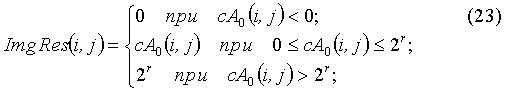
ImgRes - результирующее изображение;ImgRes - the resulting image;
нижние индексы:subscripts:
0…3 - уровни декомпозиции изображения (0-й уровень соответствует уровню изображения).0 ... 3 - levels of image decomposition (0th level corresponds to the image level).
На фиг.2 представлена схема трех уровней декомпозиции исходного изображения, где ImgSrc - исходное изображение;Figure 2 presents a diagram of three levels of decomposition of the original image, where ImgSrc is the original image;
сН - матрица горизонтальных детализирующих коэффициентов;SN - a matrix of horizontal detailing coefficients;
cV - матрица вертикальных детализирующих коэффициентов;cV is a matrix of vertical detailing coefficients;
cD - матрица диагональных детализирующих коэффициентов;cD is the matrix of diagonal detailing coefficients;
свертка следующими операторами декомпозиции:convolution by the following decomposition operators:
Fa - аппроксимирующим;Fa - approximating;
Fh - детализирующим горизонтальным;Fh - detail horizontal;
Fv - детализирующим вертикальным;Fv - detailing vertical;
Fd - детализирующим диагональным;Fd - detailing diagonal;
нижние индексы:subscripts:
1…3 - уровни декомпозиции изображения.1 ... 3 - levels of image decomposition.
На фиг.3 представлен пример функций коррекции уровней яркости (LUTa) и контраста (LUTd), полученных при обработке реального изображения,Figure 3 presents an example of the correction functions of the brightness levels (LUTa) and contrast (LUTd) obtained by processing a real image,
Где Amax - наибольшее допустимое значение коэффициентов аппроксимации на третьем уровне разложения, зависящее от количества уровней квантования исходного изображения и способа реализации декомпозиции;Where A max - the largest allowable value of the approximation coefficients at the third level of decomposition, depending on the number of quantization levels of the original image and the method of decomposition;
amin - максимальное значение коэффициентов аппроксимации обрабатываемого изображения на третьем уровне разложения;a min - the maximum value of the approximation coefficients of the processed image at the third level of decomposition;
amax - минимальное значение коэффициентов аппроксимации обрабатываемого изображения на третьем уровне разложения.a max - the minimum value of the approximation coefficients of the processed image at the third level of decomposition.
На фиг.4 представлена схема формирования семейства матриц масштабированных коэффициентов коррекции контраста,Figure 4 presents a diagram of the formation of a family of matrices of scaled contrast correction coefficients,
где М - матрица коэффициентов яркостной коррекции контраста;where M is the matrix of coefficients of brightness correction of contrast;
свертка следующими операторами реконструкции:convolution by the following reconstruction operators:
Fa~ - аппроксимирующим;Fa ~ - approximating;
Fh~ - детализирующим горизонтальным;Fh ~ - detailing horizontal;
Fv~ - детализирующим вертикальным;Fv ~ - detailing vertical;
Fd~ - детализирующим диагональным;Fd ~ - detailing diagonal;
нижние индексы:subscripts:
0…3 - уровни представления изображения (0-й уровень соответствует уровню изображения).0 ... 3 - image presentation levels (0th level corresponds to the image level).
На фиг.5 представлена схема реконструкция результирующего изображения с преобразованием контраста, сглаживания шумовой микроструктуры и повышением резкости на уровне 0 (сА0),Figure 5 presents a diagram of the reconstruction of the resulting image with the conversion of contrast, smoothing the noise microstructure and sharpening at the level of 0 (sA 0 ),
где ImgRes - результирующее изображение;where ImgRes is the resulting image;
сН - матрица горизонтальных детализирующих коэффициентов;SN - a matrix of horizontal detailing coefficients;
cV - матрица вертикальных детализирующих коэффициентов;cV is a matrix of vertical detailing coefficients;
cD - матрица диагональных детализирующих коэффициентов;cD is the matrix of diagonal detailing coefficients;
W - матрица восстановленной детализирующей составляющей;W is the matrix of the restored detailing component;
W' - матрица восстановленной детализирующей составляющей с преобразованием контраста и сглаживанием шумовой микроструктуры;W 'is the matrix of the restored detailing component with the conversion of contrast and smoothing of the noise microstructure;
W" - матрица восстановленной детализирующей составляющей с преобразованием контраста, сглаживанием шумовой микроструктуры и повышением резкости;W "is the matrix of the restored detailing component with the conversion of contrast, smoothing of the noise microstructure and sharpening;
М' - матрица преобразованных коэффициентов коррекции контраста;M 'is the matrix of the converted contrast correction coefficients;
свертка следующими операторами реконструкции:convolution by the following reconstruction operators:
Fa~ - аппроксимирующим;Fa ~ - approximating;
Fh~ - детализирующим горизонтальным;Fh ~ - detailing horizontal;
Fv~ - детализирующим вертикальным;Fv ~ - detailing vertical;
Fd~ - детализирующим диагональным;Fd ~ - detailing diagonal;
нижние индексы:subscripts:
0…3 - уровни представления изображения (0-й уровень соответствует уровню изображения).0 ... 3 - image presentation levels (0th level corresponds to the image level).
На фиг.6 представлены функция яркостно-контрастной зависимости Ω(а) реконструируемого изображения и яркостное распределение допустимых значений контраста Ωдоп(а) для нулевого уровня разложения при использовании в качестве базисной функции вейвлета Хаара.Figure 6 shows the function of the brightness-contrast dependence Ω (a) of the reconstructed image and the brightness distribution of the allowable contrast values Ω dop (a) for the zero level of decomposition when using the Haar wavelet as the basis function.
На фиг.7 представлено исходное изображение.Figure 7 presents the original image.
На фиг.8 представлено результирующее изображение, обработанное описанным способом.On Fig presents the resulting image processed in the described manner.
Способ реализуется путем выполнения (фиг.1):The method is implemented by performing (figure 1):
- декомпозиции исходного изображения на составляющие;- decomposition of the original image into components;
- формирования табличных функций яркостно-контрастной коррекции и сглаживания шумовой микроструктуры;- the formation of tabular functions of brightness-contrast correction and smoothing of the noise microstructure;
- коррекции уровней яркости;- correction of brightness levels;
- реконструкции изображения, совмещенной с коррекцией контраста, сглаживания шумовой микроструктуры и повышением резкости;- reconstruction of the image, combined with the correction of contrast, smoothing the noise microstructure and sharpening;
- согласования яркостного диапазона реконструированного изображения с параметрами видеосистемы.- coordination of the brightness range of the reconstructed image with the parameters of the video system.
Для декомпозиции и реконструкции используется дискретное двумерное стационарное вейвлет-преобразование с базисом Хаара. Стационарное вейвлет-преобразование обеспечивает эффективное шумоподавление и является гарантией того, что изменение вейвлет-коэффициентов не приведет к артефактам блочности в восстановленном изображении. Низкочастотная (аппроксимирующая) составляющая изображения отражает яркостные свойства исходного изображения. Высокочастотная (детализирующая) составляющая состоит из трех компонент, характеризующих локальные контрасты в горизонтальном, вертикальном и диагональном направлениях. Тогда повышение визуальной насыщенности изображения представляет собой согласованное преобразование яркостных (аппроксимирующей составляющей последнего уровня разложения) и контрастных характеристик (детализирующих составляющих всех уровней).For decomposition and reconstruction, a discrete two-dimensional stationary wavelet transform with a Haar basis is used. Stationary wavelet transform provides effective noise reduction and is a guarantee that changing wavelet coefficients will not lead to blocking artifacts in the reconstructed image. The low-frequency (approximating) component of the image reflects the brightness properties of the original image. The high-frequency (detail) component consists of three components characterizing local contrasts in the horizontal, vertical and diagonal directions. Then the increase in visual saturation of the image is a coordinated transformation of the brightness (approximating component of the last decomposition level) and contrast characteristics (detailing components of all levels).
Декомпозиция аппроксимирующей составляющей уровня (n-1) (cAn-1) на составляющие уровня n cAn, (cH cV cD)n производится сверткой операторами декомпозиции n-го уровня (Таблица 1). Уровень n=0 соответствует уровню изображения. Схема трех уровней декомпозиции приведена на фиг.2.The decomposition of the approximating component of the level (n-1) (cA n-1 ) into the components of the level n cA n , (cH cV cD) n is carried out by convolution of the decomposition operators of the n-th level (Table 1). Level n = 0 corresponds to the level of the image. A diagram of the three levels of decomposition is shown in figure 2.
(n=1)1st level
(n = 1)
(n=2)2nd level
(n = 2)
(n=3)3rd level
(n = 3)
![]()
![]()


![]()
![]()


![]()
![]()
![]()
![]()


Реконструкция изображения производится в обратном порядке, начиная с уровня n=3. Реконструкция коэффициентов аппроксимации уровня n (cAn) по составляющим (n+1)-го уровня cAn+1, (cH, cV cD)n+1 производится сверткой операторами реконструкции n-го уровня (Таблица 2).Image reconstruction is performed in the reverse order, starting from level n = 3. The reconstruction of the coefficients of approximation of the level n (cA n ) by the components of the (n + 1) -th level cA n + 1 , (cH, cV cD) n + 1 is carried out by convolution of the reconstruction operators of the n-th level (Table 2).
(n=3)3rd level
(n = 3)
(n=2)2nd level
(n = 2)
(n=1)1st level
(n = 1)

![]()
![]()


![]()
![]()

![]()
![]()
![]()
![]()
Определение параметров яркостно-контрастного преобразования и сглаживания шумовой микроструктуры выполняют параллельно.The determination of the parameters of the brightness-contrast conversion and smoothing of the noise microstructure is performed in parallel.
Яркостно-контрастное преобразование выполняют при помощи табличных функций коррекции яркости и контраста согласно прототипу, формируемых путем преобразования гистограммы значений аппроксимирующей составляющей с учетом особенностей зрительного восприятия следующим образом:The brightness-contrast conversion is performed using the tabular functions of brightness and contrast correction according to the prototype, formed by converting the histogram of the values of the approximating component taking into account the characteristics of visual perception as follows:
1) вычисляют нормированную гистограмму ![]()
![]()
![]()
![]()
![]()
![]()
![]()
![]()
где m - количество элементов со значением а;where m is the number of elements with a value;
amin, amax - минимальное и максимальное значения округленных коэффициентов аппроксимации;a min , a max - the minimum and maximum values of rounded approximation coefficients;
s - общее число элементов матрицы сА3;s is the total number of elements of the matrix sA 3 ;
i - номер строки; j - номер столбца.i is the line number; j is the column number.
Нормирование позволяет перейти от количественного распределения уровней яркости h(a) к яркостно-контрастному распределению ![]()
![]()
2) согласно изобретению формируют функцию F(a), характеризующую зрительное восприятие возрастающих и убывающих уровней яркостей, основываясь на формуле Вышецкого [3]:2) according to the invention form a function F (a), characterizing the visual perception of increasing and decreasing brightness levels, based on the Vyshetsky formula [3]:
![]()
![]()
функцию F(a) нормируютthe function F (a) is normalized
![]()
![]()
3) строят порождающую функцию Н(а) путем нелинейного преобразования нормированной гистограммы ![]()
![]()
![]()
![]()

4) вычисляют табличную функцию коррекции уровней яркости LUTa аппроксимирующей составляющей согласно изобретению4) calculate the tabular function of the correction of the brightness levels LUTa approximating component according to the invention

где Amax3 - максимальное значение коэффициентов аппроксимации третьего уровня разложения, зависящее от разрядности исходного изображения и варианта реализации вейвлет-декомпозиции;where A max3 is the maximum value of the approximation coefficients of the third decomposition level, which depends on the bit depth of the original image and the implementation of the wavelet decomposition;
amin, amax - минимальное и максимальное значения округленных коэффициентов аппроксимации;a min , a max - the minimum and maximum values of rounded approximation coefficients;
s - общее число элементов матрицы сА3.s is the total number of elements of the matrix sA 3 .
5) вычисляют табличную функцию коррекции контраста LUTd третьего уровня разложения, применение которой согласно изобретению позволяет сохранить мелкомасштабную детальность и обеспечить согласованное преобразование яркости и контраста:5) calculate the tabular contrast correction function LUTd of the third decomposition level, the use of which according to the invention allows preserving small-scale detail and providing a consistent conversion of brightness and contrast:

![]()
![]()
![]()
![]()
На фиг.3 представлен пример функций коррекции уровней яркости (LUTa) и контраста (LUTd), полученные при обработке реального изображения.Figure 3 presents an example of the functions of the correction of brightness levels (LUTa) and contrast (LUTd) obtained in processing a real image.
6) формируют матрицу коэффициентов преобразования локальных контрастов 3-го уровня (M3):6) form a matrix of conversion coefficients of local contrasts of the 3rd level (M 3 ):
![]()
![]()
7) для пространственного согласования на каждом уровне коэффициентов коррекции со значениями детализирующей составляющей формируют семейство матриц масштабированных коэффициентов коррекции контраста (M2, M1, M0) путем свертки матрицы М3 аппроксимирующими операторами реконструкции (фиг.4).7) for spatial matching at each level of correction coefficients with the values of the detailing component, a family of matrices of scaled contrast correction coefficients (M 2 , M 1 , M 0 ) is formed by convolution of the matrix M 3 by approximating reconstruction operators (Fig. 4).
Одновременно с (1-7) на каждом уровне разложения n выполняют следующие действия:Simultaneously with (1-7), at each decomposition level n, the following actions are performed:
8) вычисляют пространственное распределение абсолютного значения локального контраста в виде матрицы LCn, каждый элемент которой вычисляют по формуле8) calculate the spatial distribution of the absolute value of local contrast in the form of a matrix LC n , each element of which is calculated by the formula
![]()
![]()
где сН - матрица горизонтальных детализирующих коэффициентов;where SN is the matrix of horizontal detailing coefficients;
cV - матрица вертикальных детализирующих коэффициентов;cV is a matrix of vertical detailing coefficients;
cD - матрица диагональных детализирующих коэффициентов;cD is the matrix of diagonal detailing coefficients;
i - номер строки; j - номер столбца;i is the line number; j is the column number;
n=1…3 - номер уровня декомпозиции.n = 1 ... 3 is the number of the level of decomposition.
9) вычисляют пороговое значение шумовой микроструктуры согласно прототипу:9) calculate the threshold value of the noise microstructure according to the prototype:
- вычисляют гистограмму h значений элементов матрицы LCn:- calculate the histogram h of the values of the elements of the matrix LCn:
![]()
![]()
где m - число элементов со значением е.where m is the number of elements with a value of e.
- по гистограмме h вычисляется и нормируется интегральная гистограмма q:- according to the histogram h, the integral histogram q is calculated and normalized:
![]()
![]()
где emax - максимального значение элемента матрицы LCn;where e max is the maximum value of an element of the matrix LC n ;
s - общее число элементов матрицы LCn.s is the total number of elements of the matrix LC n .
- строят характеристическую функцию R(e):- build the characteristic function R (e):
![]()
![]()
- определяют значение абсолютного значения локального контраста eT, при котором значение характеристической функции R(e) минимально;- determine the absolute value of the local contrast e T at which the value of the characteristic function R (e) is minimal;
- вычисляют пороговое значение Т шумовой структуры локального контраста:- calculate the threshold value T of the noise structure of local contrast:
![]()
![]()
где Kмикр≈0.05…0.25 - коэффициент микроструктуры.where K mic ≈0.05 ... 0.25 is the microstructure coefficient.
10) формируют табличную функцию сглаживания шумовой микроструктуры (LUTnn):10) form the tabular function of smoothing the noise microstructure (LUTn n ):

![]()
![]()
![]()
![]()
где Emax n - максимальное значение локального контраста на уровне разложения n, зависящее от разрядности исходного изображения и варианта реализации вейвлет-декомпозиции.where E max n is the maximum value of local contrast at the decomposition level n, which depends on the bit depth of the original image and the implementation of the wavelet decomposition.
После формирования реконструированных матриц коэффициентов преобразования контраста (M2, M1, M0) и табличных функций сглаживания шумовой микроструктуры (LUTn3, LUTn2, LUTn1) одновременно выполняют:After the reconstructed matrices of contrast conversion coefficients (M 2 , M 1 , M 0 ) and tabular functions for smoothing the noise microstructure (LUTn 3 , LUTn 2 , LUTn 1 ) are formed simultaneously, they simultaneously perform:
- яркостную коррекцию аппроксимирующей составляющей:- brightness correction of the approximating component:
![]()
![]()
- на каждом уровне разложения n поэлементно преобразуют матрицу коэффициентов коррекции контраста Mn функцией сглаживания шумовой микроструктуры LUTnn:- at each decomposition level n, the matrix of contrast correction coefficients M n is transformed element-wise by the smoothing function of the noise microstructure LUTn n :
![]()
![]()
где М' - матрица преобразованных коэффициентов локального контраста.where M 'is the matrix of transformed local contrast coefficients.
Затем выполняют реконструкцию изображения, совмещенную с коррекцией контраста, сглаживания шумовой микроструктуры и повышением резкости, применяемую к преобразованной аппроксимирующей составляющей и детализирующим составляющим (фиг.5). Каждый уровень реконструкции состоит изThen perform image reconstruction, combined with the correction of contrast, smoothing the noise microstructure and sharpening, applied to the converted approximating component and detailed components (figure 5). Each reconstruction level consists of
- свертки матрицы коэффициентов аппроксимации и матриц детализирующих горизонтальных, вертикальных и диагональных коэффициентов операторами реконструкции;- convolutions of the matrix of approximation coefficients and matrices detailing horizontal, vertical and diagonal coefficients by reconstruction operators;
- получения матрицы восстановленной детализирующей составляющей путем поэлементного суммирования матриц детализирующих горизонтальных, вертикальных и диагональных коэффициентов, обработанных операторами реконструкции;- obtaining a matrix of the restored detailing component by elementwise summation of matrices of detailed horizontal, vertical and diagonal coefficients processed by reconstruction operators;
- преобразования матрицы восстановленной детализирующей составляющей матрицей преобразованных коэффициентов коррекции контраста;- transformations of the matrix with the restored detailed component matrix of the converted contrast correction coefficients;
- повышения мелкомасштабной детальности изображения с использованием восстановленных составляющих нулевого уровня;- increasing the small-scale detail of the image using the restored components of the zero level;
- поэлементного суммирования матриц восстановленной аппроксимирующей составляющей с преобразованной матрицей восстановленной детализирующей составляющей.- element-wise summation of the matrices of the restored approximating component with the transformed matrix of the restored detailing component.
На каждом уровне n выполняют преобразование восстановленной детализирующей составляющей W путем поэлементного умножения значений восстановленной детализирующей составляющей W на значения матрицы преобразованных коэффициентов коррекции контраста М':At each level n, the reconstructed reconstructed detail component W is converted by incrementally multiplying the values of the reconstructed detail component W by the values of the matrix of transformed contrast correction coefficients M ':
![]()
![]()
где W - матрица восстановленной детализирующей составляющей после преобразования контраста и сглаживания шумовой микроструктуры.where W is the matrix of the reconstructed detailing component after contrast conversion and smoothing of the noise microstructure.
Повышение мелкомасштабной детальности изображения осуществляют путем дополнительного поэлементного умножения значений восстановленной и преобразованной составляющей ![]()
![]()
- формируют яркостно-контрастную характеристику Ω путем поэлементного сканирования матрицы сА0 и ![]()
![]()
![]()
![]()
![]()
![]()
![]()
![]()
- определяют зависимость возможных значений коэффициентов дополнительного контрастирования от яркости K(а):- determine the dependence of the possible values of the additional contrast coefficients on the brightness K (a):
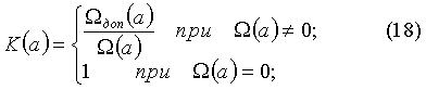
![]()
![]()
где Amax0 - наибольшее допустимое значение коэффициентов аппроксимации нулевого уровня разложения, зависящее от количества уровней квантования исходного изображения и способа реализации;where Amax 0 is the largest allowable value of the approximation coefficients of the zero decomposition level, depending on the number of quantization levels of the original image and the implementation method;
Ωдоп(а) - зависимость допустимых значений контраста от яркости для нулевого уровня разложения при использовании в качестве базисной функции вейвлета Хаара, определяемая следующим образом:Ω add (a) is the dependence of acceptable contrast values on brightness for the zero level of decomposition when using the Haar wavelet as the basis function, defined as follows:
![]()
![]()
На фиг.6 представлены яркостно-контрастная характеристика Ω(а) реконструируемого изображения и яркостное распределение допустимых значений контраста Ωдоп(а) для нулевого уровня разложения при использовании в качестве базисной функции вейвлета Хаара.Figure 6 shows the luminance-contrast characteristic Ω (a) of the reconstructed image and the luminance distribution of acceptable contrast values Ω dop (a) for the zero level of decomposition when using the Haar wavelet as the basis function.
- для ненулевых значений K(а) вычисляют среднее значение коэффициента дополнительного контрастирования ![]()
![]()
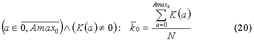
где N - количество ненулевых отсчетов K(а); нижний индекс - номер итерации.where N is the number of nonzero samples K (a); subscript - iteration number.
Итеративно уточняют среднее значение коэффициента дополнительного контрастирования, на каждой итерации i изменяя значения K(а):Iteratively specify the average value of the coefficient of additional contrast, at each iteration i changing the values of K (a):

определяют значение коэффициента повышения резкости Kr при выполнении условияdetermine the value of the sharpening coefficient Kr when the condition
![]()
![]()
где δ - значение допуска межитерационного изменения среднего значения коэффициента дополнительного контрастирования (δ≈0.1…0.001).where δ is the tolerance value of the interiterational change in the average value of the coefficient of additional contrasting (δ≈0.1 ... 0.001).
Далее выполняют поэлементное умножение значений восстановленной и преобразованной составляющей ![]()
![]()
![]()
![]()
![]()
![]()
Затем согласуют яркостной диапазон реконструированного изображения сА0 с параметрами видеосистемы следующим образом:Then, the brightness range of the reconstructed image CA 0 is matched with the parameters of the video system as follows:
- если разрядность видеосистемы r совпадает с разрядностью исходного изображения:- if the resolution of the video system r coincides with the resolution of the original image:
- иначе:- otherwise:
![]()
![]()
где ImgResmax, ImgResmin - максимальное и минимальное значения яркости результирующего изображения.where ImgRes max , ImgRes min - maximum and minimum brightness values of the resulting image.
На фиг.7 представлено исходное изображение, а на фиг.8 представлено результирующее изображение, обработанное описанным способом.In Fig.7 presents the original image, and Fig.8 presents the resulting image processed in the described manner.
Источники информацииInformation sources
1. Патент RU 2342701 «Способ комплексирования цифровых многоспектральных полутоновых изображений», МПК G06K 9/40, G06T 5/40, приоритет 15.08.2007, дата публикации 27.12.2008.1. Patent RU 2342701 “Method for integrating digital multispectral grayscale images”, IPC G06K 9/40, G06T 5/40, priority 15.08.2007, publication date 12/27/2008.
2. Дьяконов В.П. Вейвлеты. От теории к практике. - М.: СОЛОН-Р, 2002. - 448 с.2. Dyakonov V.P. Wavelets. From theory to practice. - M .: SOLON-R, 2002 .-- 448 p.
3. Шашлов Б.А. Теория фотографических процессов. -М.: Книга, 1981. - 319 с.3. Shashlov B.A. Theory of photographic processes. -M .: Book, 1981. - 319 p.
Claims (1)
Priority Applications (1)
| Application Number | Priority Date | Filing Date | Title |
|---|---|---|---|
| RU2011113884/08A RU2448367C1 (en) | 2011-04-11 | 2011-04-11 | Method of increasing visual information content of digital greyscale images |
Applications Claiming Priority (1)
| Application Number | Priority Date | Filing Date | Title |
|---|---|---|---|
| RU2011113884/08A RU2448367C1 (en) | 2011-04-11 | 2011-04-11 | Method of increasing visual information content of digital greyscale images |
Publications (1)
| Publication Number | Publication Date |
|---|---|
| RU2448367C1 true RU2448367C1 (en) | 2012-04-20 |
Family
ID=46032719
Family Applications (1)
| Application Number | Title | Priority Date | Filing Date |
|---|---|---|---|
| RU2011113884/08A RU2448367C1 (en) | 2011-04-11 | 2011-04-11 | Method of increasing visual information content of digital greyscale images |
Country Status (1)
| Country | Link |
|---|---|
| RU (1) | RU2448367C1 (en) |
Cited By (7)
| Publication number | Priority date | Publication date | Assignee | Title |
|---|---|---|---|---|
| RU2540778C1 (en) * | 2013-10-31 | 2015-02-10 | Закрытое Акционерное Общество "Научно-Технический Центр Элинс" | Method for integrating digital half-tone images |
| RU2586585C1 (en) * | 2015-04-07 | 2016-06-10 | Закрытое акционерное общество "МНИТИ" (сокращенно ЗАО "МНИТИ") | Method of increasing visual information content of digital images |
| RU2684585C1 (en) * | 2017-12-18 | 2019-04-09 | Публичное акционерное общество "Ростовский оптико-механический завод" | Method of complexing halftone television and thermal images |
| US10380447B1 (en) * | 2014-11-26 | 2019-08-13 | Google Llc | Providing regions of interest in an image |
| RU2791668C2 (en) * | 2013-05-07 | 2023-03-13 | Долби Лэборетериз Лайсенсинг Корпорейшн | Method for generation of multi-halftone images and projection with double modulation |
| US11765326B2 (en) | 2013-05-07 | 2023-09-19 | Dolby Laboratories Licensing Corporation | Multi-half-tone imaging and dual modulation projection/dual modulation laser projection |
| CN117171510A (en) * | 2023-06-14 | 2023-12-05 | 国网上海市电力公司 | A method and system for denoising white noise in partial discharge detection |
Citations (5)
| Publication number | Priority date | Publication date | Assignee | Title |
|---|---|---|---|---|
| RU2148858C1 (en) * | 1998-07-10 | 2000-05-10 | Военная академия бронетанковых войск | Method for automatic segmentation of half- tone image using brightness histogram shape |
| RU2174710C1 (en) * | 2000-03-20 | 2001-10-10 | Общевойсковая Академия Вооруженных Сил Российской Федерации | Method for automatic enhancing of half-tone image |
| EP1347414A1 (en) * | 2002-02-22 | 2003-09-24 | Agfa-Gevaert | Method for enhancing the contrast of an image. |
| RU2343538C1 (en) * | 2007-10-31 | 2009-01-10 | Закрытое Акционерное Общество "Импульс" | Method for correction of digital x-ray images |
| RU2358319C2 (en) * | 2003-08-29 | 2009-06-10 | Самсунг Электроникс Ко., Лтд. | Method and device for photorealistic three dimensional simulation of face based on image |
-
2011
- 2011-04-11 RU RU2011113884/08A patent/RU2448367C1/en not_active IP Right Cessation
Patent Citations (5)
| Publication number | Priority date | Publication date | Assignee | Title |
|---|---|---|---|---|
| RU2148858C1 (en) * | 1998-07-10 | 2000-05-10 | Военная академия бронетанковых войск | Method for automatic segmentation of half- tone image using brightness histogram shape |
| RU2174710C1 (en) * | 2000-03-20 | 2001-10-10 | Общевойсковая Академия Вооруженных Сил Российской Федерации | Method for automatic enhancing of half-tone image |
| EP1347414A1 (en) * | 2002-02-22 | 2003-09-24 | Agfa-Gevaert | Method for enhancing the contrast of an image. |
| RU2358319C2 (en) * | 2003-08-29 | 2009-06-10 | Самсунг Электроникс Ко., Лтд. | Method and device for photorealistic three dimensional simulation of face based on image |
| RU2343538C1 (en) * | 2007-10-31 | 2009-01-10 | Закрытое Акционерное Общество "Импульс" | Method for correction of digital x-ray images |
Cited By (8)
| Publication number | Priority date | Publication date | Assignee | Title |
|---|---|---|---|---|
| RU2791668C2 (en) * | 2013-05-07 | 2023-03-13 | Долби Лэборетериз Лайсенсинг Корпорейшн | Method for generation of multi-halftone images and projection with double modulation |
| US11765326B2 (en) | 2013-05-07 | 2023-09-19 | Dolby Laboratories Licensing Corporation | Multi-half-tone imaging and dual modulation projection/dual modulation laser projection |
| RU2540778C1 (en) * | 2013-10-31 | 2015-02-10 | Закрытое Акционерное Общество "Научно-Технический Центр Элинс" | Method for integrating digital half-tone images |
| US10380447B1 (en) * | 2014-11-26 | 2019-08-13 | Google Llc | Providing regions of interest in an image |
| RU2586585C1 (en) * | 2015-04-07 | 2016-06-10 | Закрытое акционерное общество "МНИТИ" (сокращенно ЗАО "МНИТИ") | Method of increasing visual information content of digital images |
| RU2684585C1 (en) * | 2017-12-18 | 2019-04-09 | Публичное акционерное общество "Ростовский оптико-механический завод" | Method of complexing halftone television and thermal images |
| CN117171510A (en) * | 2023-06-14 | 2023-12-05 | 国网上海市电力公司 | A method and system for denoising white noise in partial discharge detection |
| RU2843097C1 (en) * | 2024-11-05 | 2025-07-07 | Федеральное государственное бюджетное образовательное учреждение высшего образования "Тамбовский государственный технический университет" (ФГБОУ ВО "ТГТУ") | Method for complexing digital halftone images |
Similar Documents
| Publication | Publication Date | Title |
|---|---|---|
| Suganya et al. | Survey on image enhancement techniques | |
| Gupta et al. | Review of different local and global contrast enhancement techniques for a digital image | |
| RU2342701C1 (en) | Method of complexing digital multispectral half-tone images | |
| RU2448367C1 (en) | Method of increasing visual information content of digital greyscale images | |
| KR20160102524A (en) | Method for inverse tone mapping of an image | |
| Cho et al. | Fast image enhancement in compressed wavelet domain | |
| CN105096280A (en) | Method and device for processing image noise | |
| Gopinathan et al. | Wavelet and FFT Based Image Denoising Using Non-Linear Filters. | |
| Singh et al. | Satellite image enhancement using beta wavelet based gamma corrected adaptive knee transformation | |
| US9111339B1 (en) | System and method for reducing noise from an image | |
| Bagawade Ramdas et al. | Wavelet transform techniques for image resolution enhancement: a study | |
| CN101889295A (en) | Method for generating multi-scale contrast-enhanced images | |
| CN110322404A (en) | A kind of image enchancing method and system | |
| Kaur et al. | Image de-noising using wavelet transform and various filters | |
| Hossain et al. | Medical image enhancement based on nonlinear technique and logarithmic transform coefficient histogram matching | |
| Unni | Satellite image enhancement using 2D level DWT | |
| Ferzo et al. | Image denoising in wavelet domain based on thresholding with applying wiener filter | |
| Zhang et al. | Adaptive typhoon cloud image enhancement using genetic algorithm and non-linear gain operation in undecimated wavelet domain | |
| Pai et al. | Medical color image enhancement using wavelet transform and contrast stretching technique | |
| Kawasaki et al. | A multiscale retinex based on wavelet transformation | |
| Gazal et al. | Lwt-clahe based color image enhancement technique: An improved design | |
| Albu | Linear prediction based image enhancement method | |
| Pyo et al. | Noise reduction in high-ISO images using 3-D collaborative filtering and structure extraction from residual blocks | |
| Ha et al. | Remote sensing image enhancement based on singular value decomposition | |
| Unaldi et al. | Undecimated wavelet transform based contrast enhancement |
Legal Events
| Date | Code | Title | Description |
|---|---|---|---|
| MM4A | The patent is invalid due to non-payment of fees |
Effective date: 20160412 |