RU2390288C2 - Body-protection device - Google Patents
Body-protection device Download PDFInfo
- Publication number
- RU2390288C2 RU2390288C2 RU2006126156/12A RU2006126156A RU2390288C2 RU 2390288 C2 RU2390288 C2 RU 2390288C2 RU 2006126156/12 A RU2006126156/12 A RU 2006126156/12A RU 2006126156 A RU2006126156 A RU 2006126156A RU 2390288 C2 RU2390288 C2 RU 2390288C2
- Authority
- RU
- Russia
- Prior art keywords
- tube
- side wall
- essentially
- tubes
- matrix
- Prior art date
Links
- 239000011159 matrix material Substances 0.000 claims abstract description 21
- 239000000463 material Substances 0.000 claims description 68
- 230000001681 protective effect Effects 0.000 claims description 16
- 238000002844 melting Methods 0.000 claims description 15
- 230000008018 melting Effects 0.000 claims description 15
- 239000003292 glue Substances 0.000 claims description 12
- 239000000126 substance Substances 0.000 abstract 1
- 239000011162 core material Substances 0.000 description 17
- 238000000034 method Methods 0.000 description 11
- 230000015572 biosynthetic process Effects 0.000 description 9
- 241000264877 Hippospongia communis Species 0.000 description 8
- 239000000853 adhesive Substances 0.000 description 7
- 230000001070 adhesive effect Effects 0.000 description 7
- 238000005452 bending Methods 0.000 description 7
- 208000010392 Bone Fractures Diseases 0.000 description 6
- 206010017076 Fracture Diseases 0.000 description 6
- 239000004697 Polyetherimide Substances 0.000 description 5
- 230000007935 neutral effect Effects 0.000 description 5
- 229920001601 polyetherimide Polymers 0.000 description 5
- 238000010521 absorption reaction Methods 0.000 description 4
- 239000004033 plastic Substances 0.000 description 4
- 229920003023 plastic Polymers 0.000 description 4
- 230000000750 progressive effect Effects 0.000 description 4
- 230000004044 response Effects 0.000 description 4
- 239000002131 composite material Substances 0.000 description 3
- 230000006835 compression Effects 0.000 description 3
- 238000007906 compression Methods 0.000 description 3
- 230000006378 damage Effects 0.000 description 3
- -1 polyethylene terephthalate Polymers 0.000 description 3
- 230000035939 shock Effects 0.000 description 3
- 239000004695 Polyether sulfone Substances 0.000 description 2
- 229920000491 Polyphenylsulfone Polymers 0.000 description 2
- 239000004743 Polypropylene Substances 0.000 description 2
- 238000010276 construction Methods 0.000 description 2
- 238000001816 cooling Methods 0.000 description 2
- 239000000835 fiber Substances 0.000 description 2
- 238000010438 heat treatment Methods 0.000 description 2
- 230000006872 improvement Effects 0.000 description 2
- 210000003127 knee Anatomy 0.000 description 2
- 229910052751 metal Inorganic materials 0.000 description 2
- 239000002184 metal Substances 0.000 description 2
- 239000004417 polycarbonate Substances 0.000 description 2
- 229920000515 polycarbonate Polymers 0.000 description 2
- 229920006393 polyether sulfone Polymers 0.000 description 2
- 229920001155 polypropylene Polymers 0.000 description 2
- 238000003856 thermoforming Methods 0.000 description 2
- OKTJSMMVPCPJKN-UHFFFAOYSA-N Carbon Chemical compound [C] OKTJSMMVPCPJKN-UHFFFAOYSA-N 0.000 description 1
- 229920002430 Fibre-reinforced plastic Polymers 0.000 description 1
- 239000011358 absorbing material Substances 0.000 description 1
- 229910052782 aluminium Inorganic materials 0.000 description 1
- XAGFODPZIPBFFR-UHFFFAOYSA-N aluminium Chemical compound [Al] XAGFODPZIPBFFR-UHFFFAOYSA-N 0.000 description 1
- 229910052799 carbon Inorganic materials 0.000 description 1
- 230000007423 decrease Effects 0.000 description 1
- 239000011151 fibre-reinforced plastic Substances 0.000 description 1
- 239000006260 foam Substances 0.000 description 1
- 230000004927 fusion Effects 0.000 description 1
- 239000011521 glass Substances 0.000 description 1
- 230000000977 initiatory effect Effects 0.000 description 1
- 230000003993 interaction Effects 0.000 description 1
- 230000007246 mechanism Effects 0.000 description 1
- 239000000203 mixture Substances 0.000 description 1
- 230000004048 modification Effects 0.000 description 1
- 238000012986 modification Methods 0.000 description 1
- 229920000728 polyester Polymers 0.000 description 1
- 229920000139 polyethylene terephthalate Polymers 0.000 description 1
- 239000005020 polyethylene terephthalate Substances 0.000 description 1
- 229920000642 polymer Polymers 0.000 description 1
- 239000002861 polymer material Substances 0.000 description 1
- 230000008569 process Effects 0.000 description 1
- 230000009467 reduction Effects 0.000 description 1
- 239000012858 resilient material Substances 0.000 description 1
- 239000005060 rubber Substances 0.000 description 1
- 229920001169 thermoplastic Polymers 0.000 description 1
- 239000004416 thermosoftening plastic Substances 0.000 description 1
- 238000003466 welding Methods 0.000 description 1
Images


Classifications
-
- A—HUMAN NECESSITIES
- A42—HEADWEAR
- A42B—HATS; HEAD COVERINGS
- A42B3/00—Helmets; Helmet covers ; Other protective head coverings
- A42B3/04—Parts, details or accessories of helmets
- A42B3/06—Impact-absorbing shells, e.g. of crash helmets
- A42B3/062—Impact-absorbing shells, e.g. of crash helmets with reinforcing means
- A42B3/063—Impact-absorbing shells, e.g. of crash helmets with reinforcing means using layered structures
-
- B—PERFORMING OPERATIONS; TRANSPORTING
- B32—LAYERED PRODUCTS
- B32B—LAYERED PRODUCTS, i.e. PRODUCTS BUILT-UP OF STRATA OF FLAT OR NON-FLAT, e.g. CELLULAR OR HONEYCOMB, FORM
- B32B3/00—Layered products comprising a layer with external or internal discontinuities or unevennesses, or a layer of non-planar shape; Layered products comprising a layer having particular features of form
- B32B3/10—Layered products comprising a layer with external or internal discontinuities or unevennesses, or a layer of non-planar shape; Layered products comprising a layer having particular features of form characterised by a discontinuous layer, i.e. formed of separate pieces of material
- B32B3/12—Layered products comprising a layer with external or internal discontinuities or unevennesses, or a layer of non-planar shape; Layered products comprising a layer having particular features of form characterised by a discontinuous layer, i.e. formed of separate pieces of material characterised by a layer of regularly- arranged cells, e.g. a honeycomb structure
-
- A—HUMAN NECESSITIES
- A41—WEARING APPAREL
- A41D—OUTERWEAR; PROTECTIVE GARMENTS; ACCESSORIES
- A41D31/00—Materials specially adapted for outerwear
- A41D31/04—Materials specially adapted for outerwear characterised by special function or use
- A41D31/24—Resistant to mechanical stress, e.g. pierce-proof
- A41D31/245—Resistant to mechanical stress, e.g. pierce-proof using layered materials
-
- A—HUMAN NECESSITIES
- A41—WEARING APPAREL
- A41D—OUTERWEAR; PROTECTIVE GARMENTS; ACCESSORIES
- A41D31/00—Materials specially adapted for outerwear
- A41D31/04—Materials specially adapted for outerwear characterised by special function or use
- A41D31/28—Shock absorbing
- A41D31/285—Shock absorbing using layered materials
-
- A—HUMAN NECESSITIES
- A42—HEADWEAR
- A42B—HATS; HEAD COVERINGS
- A42B3/00—Helmets; Helmet covers ; Other protective head coverings
- A42B3/04—Parts, details or accessories of helmets
- A42B3/06—Impact-absorbing shells, e.g. of crash helmets
- A42B3/062—Impact-absorbing shells, e.g. of crash helmets with reinforcing means
- A42B3/063—Impact-absorbing shells, e.g. of crash helmets with reinforcing means using layered structures
- A42B3/064—Impact-absorbing shells, e.g. of crash helmets with reinforcing means using layered structures with relative movement between layers
-
- A—HUMAN NECESSITIES
- A42—HEADWEAR
- A42B—HATS; HEAD COVERINGS
- A42B3/00—Helmets; Helmet covers ; Other protective head coverings
- A42B3/04—Parts, details or accessories of helmets
- A42B3/10—Linings
- A42B3/12—Cushioning devices
-
- A—HUMAN NECESSITIES
- A42—HEADWEAR
- A42C—MANUFACTURING OR TRIMMING HEAD COVERINGS, e.g. HATS
- A42C2/00—Manufacturing helmets by processes not otherwise provided for
-
- A—HUMAN NECESSITIES
- A63—SPORTS; GAMES; AMUSEMENTS
- A63B—APPARATUS FOR PHYSICAL TRAINING, GYMNASTICS, SWIMMING, CLIMBING, OR FENCING; BALL GAMES; TRAINING EQUIPMENT
- A63B71/00—Games or sports accessories not covered in groups A63B1/00 - A63B69/00
- A63B71/08—Body-protectors for players or sportsmen, i.e. body-protecting accessories affording protection of body parts against blows or collisions
-
- B—PERFORMING OPERATIONS; TRANSPORTING
- B29—WORKING OF PLASTICS; WORKING OF SUBSTANCES IN A PLASTIC STATE IN GENERAL
- B29C—SHAPING OR JOINING OF PLASTICS; SHAPING OF MATERIAL IN A PLASTIC STATE, NOT OTHERWISE PROVIDED FOR; AFTER-TREATMENT OF THE SHAPED PRODUCTS, e.g. REPAIRING
- B29C43/00—Compression moulding, i.e. applying external pressure to flow the moulding material; Apparatus therefor
- B29C43/02—Compression moulding, i.e. applying external pressure to flow the moulding material; Apparatus therefor of articles of definite length, i.e. discrete articles
- B29C43/20—Making multilayered or multicoloured articles
- B29C43/203—Making multilayered articles
-
- B—PERFORMING OPERATIONS; TRANSPORTING
- B29—WORKING OF PLASTICS; WORKING OF SUBSTANCES IN A PLASTIC STATE IN GENERAL
- B29C—SHAPING OR JOINING OF PLASTICS; SHAPING OF MATERIAL IN A PLASTIC STATE, NOT OTHERWISE PROVIDED FOR; AFTER-TREATMENT OF THE SHAPED PRODUCTS, e.g. REPAIRING
- B29C51/00—Shaping by thermoforming, i.e. shaping sheets or sheet like preforms after heating, e.g. shaping sheets in matched moulds or by deep-drawing; Apparatus therefor
- B29C51/02—Combined thermoforming and manufacture of the preform
-
- B—PERFORMING OPERATIONS; TRANSPORTING
- B29—WORKING OF PLASTICS; WORKING OF SUBSTANCES IN A PLASTIC STATE IN GENERAL
- B29C—SHAPING OR JOINING OF PLASTICS; SHAPING OF MATERIAL IN A PLASTIC STATE, NOT OTHERWISE PROVIDED FOR; AFTER-TREATMENT OF THE SHAPED PRODUCTS, e.g. REPAIRING
- B29C51/00—Shaping by thermoforming, i.e. shaping sheets or sheet like preforms after heating, e.g. shaping sheets in matched moulds or by deep-drawing; Apparatus therefor
- B29C51/08—Deep drawing or matched-mould forming, i.e. using mechanical means only
- B29C51/082—Deep drawing or matched-mould forming, i.e. using mechanical means only by shaping between complementary mould parts
- B29C51/085—Deep drawing or matched-mould forming, i.e. using mechanical means only by shaping between complementary mould parts with at least one of the shaping surfaces being made of resilien material, e.g. rubber
-
- B—PERFORMING OPERATIONS; TRANSPORTING
- B29—WORKING OF PLASTICS; WORKING OF SUBSTANCES IN A PLASTIC STATE IN GENERAL
- B29C—SHAPING OR JOINING OF PLASTICS; SHAPING OF MATERIAL IN A PLASTIC STATE, NOT OTHERWISE PROVIDED FOR; AFTER-TREATMENT OF THE SHAPED PRODUCTS, e.g. REPAIRING
- B29C51/00—Shaping by thermoforming, i.e. shaping sheets or sheet like preforms after heating, e.g. shaping sheets in matched moulds or by deep-drawing; Apparatus therefor
- B29C51/14—Shaping by thermoforming, i.e. shaping sheets or sheet like preforms after heating, e.g. shaping sheets in matched moulds or by deep-drawing; Apparatus therefor using multilayered preforms or sheets
- B29C51/145—Shaping by thermoforming, i.e. shaping sheets or sheet like preforms after heating, e.g. shaping sheets in matched moulds or by deep-drawing; Apparatus therefor using multilayered preforms or sheets having at least one layer of textile or fibrous material combined with at least one plastics layer
-
- B—PERFORMING OPERATIONS; TRANSPORTING
- B32—LAYERED PRODUCTS
- B32B—LAYERED PRODUCTS, i.e. PRODUCTS BUILT-UP OF STRATA OF FLAT OR NON-FLAT, e.g. CELLULAR OR HONEYCOMB, FORM
- B32B27/00—Layered products comprising a layer of synthetic resin
-
- B—PERFORMING OPERATIONS; TRANSPORTING
- B32—LAYERED PRODUCTS
- B32B—LAYERED PRODUCTS, i.e. PRODUCTS BUILT-UP OF STRATA OF FLAT OR NON-FLAT, e.g. CELLULAR OR HONEYCOMB, FORM
- B32B7/00—Layered products characterised by the relation between layers; Layered products characterised by the relative orientation of features between layers, or by the relative values of a measurable parameter between layers, i.e. products comprising layers having different physical, chemical or physicochemical properties; Layered products characterised by the interconnection of layers
- B32B7/04—Interconnection of layers
- B32B7/12—Interconnection of layers using interposed adhesives or interposed materials with bonding properties
-
- F—MECHANICAL ENGINEERING; LIGHTING; HEATING; WEAPONS; BLASTING
- F16—ENGINEERING ELEMENTS AND UNITS; GENERAL MEASURES FOR PRODUCING AND MAINTAINING EFFECTIVE FUNCTIONING OF MACHINES OR INSTALLATIONS; THERMAL INSULATION IN GENERAL
- F16F—SPRINGS; SHOCK-ABSORBERS; MEANS FOR DAMPING VIBRATION
- F16F1/00—Springs
- F16F1/36—Springs made of rubber or other material having high internal friction, e.g. thermoplastic elastomers
- F16F1/37—Springs made of rubber or other material having high internal friction, e.g. thermoplastic elastomers of foam-like material, i.e. microcellular material, e.g. sponge rubber
-
- F—MECHANICAL ENGINEERING; LIGHTING; HEATING; WEAPONS; BLASTING
- F16—ENGINEERING ELEMENTS AND UNITS; GENERAL MEASURES FOR PRODUCING AND MAINTAINING EFFECTIVE FUNCTIONING OF MACHINES OR INSTALLATIONS; THERMAL INSULATION IN GENERAL
- F16F—SPRINGS; SHOCK-ABSORBERS; MEANS FOR DAMPING VIBRATION
- F16F7/00—Vibration-dampers; Shock-absorbers
- F16F7/12—Vibration-dampers; Shock-absorbers using plastic deformation of members
- F16F7/121—Vibration-dampers; Shock-absorbers using plastic deformation of members the members having a cellular, e.g. honeycomb, structure
-
- B—PERFORMING OPERATIONS; TRANSPORTING
- B29—WORKING OF PLASTICS; WORKING OF SUBSTANCES IN A PLASTIC STATE IN GENERAL
- B29C—SHAPING OR JOINING OF PLASTICS; SHAPING OF MATERIAL IN A PLASTIC STATE, NOT OTHERWISE PROVIDED FOR; AFTER-TREATMENT OF THE SHAPED PRODUCTS, e.g. REPAIRING
- B29C51/00—Shaping by thermoforming, i.e. shaping sheets or sheet like preforms after heating, e.g. shaping sheets in matched moulds or by deep-drawing; Apparatus therefor
- B29C51/006—Shaping by thermoforming, i.e. shaping sheets or sheet like preforms after heating, e.g. shaping sheets in matched moulds or by deep-drawing; Apparatus therefor for making articles having hollow walls
-
- B—PERFORMING OPERATIONS; TRANSPORTING
- B29—WORKING OF PLASTICS; WORKING OF SUBSTANCES IN A PLASTIC STATE IN GENERAL
- B29C—SHAPING OR JOINING OF PLASTICS; SHAPING OF MATERIAL IN A PLASTIC STATE, NOT OTHERWISE PROVIDED FOR; AFTER-TREATMENT OF THE SHAPED PRODUCTS, e.g. REPAIRING
- B29C51/00—Shaping by thermoforming, i.e. shaping sheets or sheet like preforms after heating, e.g. shaping sheets in matched moulds or by deep-drawing; Apparatus therefor
- B29C51/08—Deep drawing or matched-mould forming, i.e. using mechanical means only
- B29C51/082—Deep drawing or matched-mould forming, i.e. using mechanical means only by shaping between complementary mould parts
-
- B—PERFORMING OPERATIONS; TRANSPORTING
- B29—WORKING OF PLASTICS; WORKING OF SUBSTANCES IN A PLASTIC STATE IN GENERAL
- B29K—INDEXING SCHEME ASSOCIATED WITH SUBCLASSES B29B, B29C OR B29D, RELATING TO MOULDING MATERIALS OR TO MATERIALS FOR MOULDS, REINFORCEMENTS, FILLERS OR PREFORMED PARTS, e.g. INSERTS
- B29K2023/00—Use of polyalkenes or derivatives thereof as moulding material
- B29K2023/10—Polymers of propylene
- B29K2023/12—PP, i.e. polypropylene
-
- B—PERFORMING OPERATIONS; TRANSPORTING
- B29—WORKING OF PLASTICS; WORKING OF SUBSTANCES IN A PLASTIC STATE IN GENERAL
- B29K—INDEXING SCHEME ASSOCIATED WITH SUBCLASSES B29B, B29C OR B29D, RELATING TO MOULDING MATERIALS OR TO MATERIALS FOR MOULDS, REINFORCEMENTS, FILLERS OR PREFORMED PARTS, e.g. INSERTS
- B29K2069/00—Use of PC, i.e. polycarbonates or derivatives thereof, as moulding material
-
- B—PERFORMING OPERATIONS; TRANSPORTING
- B29—WORKING OF PLASTICS; WORKING OF SUBSTANCES IN A PLASTIC STATE IN GENERAL
- B29K—INDEXING SCHEME ASSOCIATED WITH SUBCLASSES B29B, B29C OR B29D, RELATING TO MOULDING MATERIALS OR TO MATERIALS FOR MOULDS, REINFORCEMENTS, FILLERS OR PREFORMED PARTS, e.g. INSERTS
- B29K2079/00—Use of polymers having nitrogen, with or without oxygen or carbon only, in the main chain, not provided for in groups B29K2061/00 - B29K2077/00, as moulding material
- B29K2079/08—PI, i.e. polyimides or derivatives thereof
- B29K2079/085—Thermoplastic polyimides, e.g. polyesterimides, PEI, i.e. polyetherimides, or polyamideimides; Derivatives thereof
-
- B—PERFORMING OPERATIONS; TRANSPORTING
- B29—WORKING OF PLASTICS; WORKING OF SUBSTANCES IN A PLASTIC STATE IN GENERAL
- B29L—INDEXING SCHEME ASSOCIATED WITH SUBCLASS B29C, RELATING TO PARTICULAR ARTICLES
- B29L2009/00—Layered products
- B29L2009/001—Layered products the layers being loose
-
- B—PERFORMING OPERATIONS; TRANSPORTING
- B29—WORKING OF PLASTICS; WORKING OF SUBSTANCES IN A PLASTIC STATE IN GENERAL
- B29L—INDEXING SCHEME ASSOCIATED WITH SUBCLASS B29C, RELATING TO PARTICULAR ARTICLES
- B29L2031/00—Other particular articles
- B29L2031/48—Wearing apparel
- B29L2031/4807—Headwear
- B29L2031/4814—Hats
- B29L2031/4821—Helmets
-
- B—PERFORMING OPERATIONS; TRANSPORTING
- B29—WORKING OF PLASTICS; WORKING OF SUBSTANCES IN A PLASTIC STATE IN GENERAL
- B29L—INDEXING SCHEME ASSOCIATED WITH SUBCLASS B29C, RELATING TO PARTICULAR ARTICLES
- B29L2031/00—Other particular articles
- B29L2031/60—Multitubular or multicompartmented articles, e.g. honeycomb
- B29L2031/608—Honeycomb structures
-
- B—PERFORMING OPERATIONS; TRANSPORTING
- B32—LAYERED PRODUCTS
- B32B—LAYERED PRODUCTS, i.e. PRODUCTS BUILT-UP OF STRATA OF FLAT OR NON-FLAT, e.g. CELLULAR OR HONEYCOMB, FORM
- B32B2305/00—Condition, form or state of the layers or laminate
- B32B2305/02—Cellular or porous
- B32B2305/024—Honeycomb
-
- B—PERFORMING OPERATIONS; TRANSPORTING
- B32—LAYERED PRODUCTS
- B32B—LAYERED PRODUCTS, i.e. PRODUCTS BUILT-UP OF STRATA OF FLAT OR NON-FLAT, e.g. CELLULAR OR HONEYCOMB, FORM
- B32B2437/00—Clothing
-
- Y—GENERAL TAGGING OF NEW TECHNOLOGICAL DEVELOPMENTS; GENERAL TAGGING OF CROSS-SECTIONAL TECHNOLOGIES SPANNING OVER SEVERAL SECTIONS OF THE IPC; TECHNICAL SUBJECTS COVERED BY FORMER USPC CROSS-REFERENCE ART COLLECTIONS [XRACs] AND DIGESTS
- Y10—TECHNICAL SUBJECTS COVERED BY FORMER USPC
- Y10T—TECHNICAL SUBJECTS COVERED BY FORMER US CLASSIFICATION
- Y10T156/00—Adhesive bonding and miscellaneous chemical manufacture
- Y10T156/10—Methods of surface bonding and/or assembly therefor
Landscapes
- Engineering & Computer Science (AREA)
- Mechanical Engineering (AREA)
- General Engineering & Computer Science (AREA)
- Textile Engineering (AREA)
- Manufacturing & Machinery (AREA)
- Health & Medical Sciences (AREA)
- General Health & Medical Sciences (AREA)
- Physical Education & Sports Medicine (AREA)
- Helmets And Other Head Coverings (AREA)
- Professional, Industrial, Or Sporting Protective Garments (AREA)
- Laminated Bodies (AREA)
- Braking Arrangements (AREA)
- Lining Or Joining Of Plastics Or The Like (AREA)
- Window Of Vehicle (AREA)
- Surgical Instruments (AREA)
- Investigating Or Analyzing Materials By The Use Of Ultrasonic Waves (AREA)
- Registering, Tensioning, Guiding Webs, And Rollers Therefor (AREA)
- Physical Or Chemical Processes And Apparatus (AREA)
- Prostheses (AREA)
- Cable Accessories (AREA)
- Finger-Pressure Massage (AREA)
Abstract
Description
Данное изобретение относится к защищающим тело устройствам. В частности, но не ограничиваясь этим, изобретение относится к поглощающим энергию материалам, используемым в устройствах, имеющих относительно большую кривизну, таких как защитные шлемы, налокотники, наколенники, наплечники и т.п., и к способу формирования таких материалов.The present invention relates to body protecting devices. In particular, but not limited to, the invention relates to energy-absorbing materials used in devices having a relatively large curvature, such as protective helmets, elbow pads, knee pads, shoulder pads and the like, and to a method for forming such materials.
Многие защищающее тело устройства имеют большую кривизну κ, которая определяется как обратная величина радиуса ρ кривизны устройства. Устройство, такое как защитный шлем, может требовать постоянно изогнутую форму. Другие устройства, такие как налокотники, наколенники и наплечники, должны быть достаточно гибкими для принятия изогнутой формы в ответ на движение тела. Для этих устройств необходимо использовать подходящие материалы и способы формирования.Many devices protecting the body of the device have a large curvature κ, which is defined as the reciprocal of the radius ρ of the curvature of the device. A device, such as a safety helmet, may require a constantly curved shape. Other devices, such as elbow pads, knee pads, and shoulder pads, must be flexible enough to be curved in response to body movement. For these devices, it is necessary to use suitable materials and methods of formation.
Защитные шлемы обычно содержат, по существу, сфероидный наружный слой из жесткого пластмассового материала и внутренний слой из упругого материала, такого как твердый пенопласт. Жесткий наружный слой передает ударную нагрузку более равномерно на внутреннюю оболочку, которая поглощает энергию, вызываемую ударной нагрузкой. Шлемы формируют в матрице или вокруг пуансона, и материалы должны подвергаться значительному изгибу для образования сфероидной формы. Кроме того, наружный и внутренний слои необходимо вводить в форму по отдельности. В противном случае, во время изгиба связь между двумя материалами может предотвращать необходимое скольжение наружного слоя (который растягивается) относительно внутреннего слоя (который сжимается) или же будут образовываться большие плоские напряжения на внутренней и наружной поверхностях.Protective helmets typically comprise a substantially spheroidal outer layer of hard plastic material and an inner layer of resilient material, such as rigid foam. The rigid outer layer transfers the shock load more evenly to the inner shell, which absorbs the energy caused by the shock load. Helmets are formed in the matrix or around the punch, and the materials must undergo significant bending to form a spheroid shape. In addition, the outer and inner layers must be entered into the form separately. Otherwise, during bending, the bond between the two materials can prevent the necessary sliding of the outer layer (which is stretched) relative to the inner layer (which is compressed) or large flat stresses will form on the inner and outer surfaces.
Может быть желательным уменьшение полной массы шлема. Кроме того, способы формирования шлемов, которые обычно включают ручную укладку, являются сложными и дорогими. Предпочтительно иметь возможность введения внутреннего и наружного слоя в форму в виде одного куска материала.A reduction in the total mass of the helmet may be desirable. In addition, methods for forming helmets, which typically include manual styling, are complex and expensive. It is preferable to be able to introduce the inner and outer layer into the mold in the form of a single piece of material.
В течение некоторого времени использовали нагруженные в осевом направлении колонны с различными формами поперечного сечения для улучшения структурной стойкости к ударным нагрузкам автомобилей, дорожной фурнитуры и т.п. Колонны каждой из этих известных систем обычно не соединены и работают независимо друг от друга. Независимо от материала, из которого сформированы колонны, необходимо исключать режим полной потери устойчивости (или местной потери устойчивости, которая приводит к потере устойчивости всей колонны), поскольку при этом неэффективно поглощается энергия удара.For some time, axially-loaded columns with various cross-sectional shapes were used to improve the structural resistance to shock loads of automobiles, road fittings, etc. The columns of each of these known systems are usually not connected and operate independently of each other. Regardless of the material from which the columns are formed, it is necessary to exclude the regime of complete loss of stability (or local loss of stability, which leads to loss of stability of the entire column), since the impact energy is not effectively absorbed.
Желательно, чтобы металлические колонны имели режим множественной локальной потери устойчивости и разрушения при изгибе, который является эффективным для поглощения энергии удара. Пластмассовые и композитные колонны имеют несколько режимов разрушения, которые являются эффективными для поглощения энергии удара, однако все эти режимы обычно включают прогрессивное разрушение одного конца колонны.It is desirable that the metal columns have a multiple local buckling and bending failure mode that is effective for absorbing impact energy. Plastic and composite columns have several fracture modes that are effective in absorbing impact energy, however, all these modes typically include progressive fracture of one end of the column.
Характеристики и режим разрушения пластмассовых и композитных колонн зависят от сложного взаимодействия нескольких различных параметров, включая используемый материал, геометрию (форму и толщину), выравнивание волокон в композитных материалах, использование механизмов инициирования и условий нагрузки. Однако тщательный выбор этих параметров может приводить к созданию защитного устройства, превосходящего по рабочим характеристикам металлический эквивалент.The characteristics and fracture mode of plastic and composite columns depend on the complex interaction of several different parameters, including the material used, geometry (shape and thickness), fiber alignment in composite materials, the use of initiation mechanisms and loading conditions. However, a careful selection of these parameters can lead to the creation of a protective device that surpasses the metal equivalent in performance.
Было установлено, что независимо от используемого материала матрица из независимых колонн, расположенных параллельно нагрузке, увеличивает в целом характеристики поглощения энергии и увеличивает устойчивость защитного устройства. Колонны имеют тенденцию к созданию относительно постоянного уровня поглощения энергии при прогрессивном изгибе или разрушении колонны. Было установлено, что нагруженные в осевом направлении конусы создают больше линейно увеличивающуюся степень поглощения энергии, которая может быть часто более желательной в условиях столкновения. Однако поскольку колонны являются независимыми, то локальная нагрузка может вызывать нежелательное полное разрушение колонн, которые имеют оси, смещенные относительно оси прикладываемой нагрузки. Кроме того, поскольку колонны являются независимыми, то колонны необходимо выполнять относительно толстыми для исключения неустойчивости при нагрузке.It was found that, regardless of the material used, a matrix of independent columns parallel to the load increases the overall energy absorption characteristics and increases the stability of the protective device. Columns tend to create a relatively constant level of energy absorption during progressive bending or destruction of the column. It has been found that axially loaded cones create a more linearly increasing degree of energy absorption, which can often be more desirable in a collision environment. However, since the columns are independent, local loading can cause undesirable complete destruction of the columns, which have axes that are offset from the axis of the applied load. In addition, since the columns are independent, the columns must be made relatively thick to avoid instability under load.
Многослойные панели, состоящие из жестких наружных слоев, разделенных материалом сердечника, имеющим меньшую жесткость, используют в различных применениях, таких как строительные компоненты и структурные панели для дорожных транспортных средств и самолетов. Обычно сердечник состоит из сотовой структуры, т.е. матрицы ячеек, при этом каждая ячейка имеет шестиугольное поперечное сечение. Однако эти ячейки или ячейки с другим поперечным сечением нельзя рассматривать в качестве соединительных колонн, поскольку каждая боковая сторона совместно используется смежными ячейками. Если одна ячейка подвергается местному разрушению или потере устойчивости, то это оказывает влияние на смежные ячейки.Multilayer panels consisting of rigid outer layers separated by a core material having lower rigidity are used in various applications, such as building components and structural panels for road vehicles and airplanes. Typically, the core consists of a honeycomb structure, i.e. matrix cells, with each cell having a hexagonal cross section. However, these cells or cells with a different cross section cannot be considered as connecting columns, since each side is shared by adjacent cells. If one cell undergoes local destruction or loss of stability, then this affects the adjacent cells.
Ось каждого продольного элемента перпендикулярна плоскости внутреннего или наружного слоя, и каждый конец каждого продольного элемента обычно соединен с соответствующим слоем. Поэтому сотовая структура представляет матрицу ячеек, расположенных параллельно нагрузке, которая ударяет в плоскость одного из наружных слоев.The axis of each longitudinal element is perpendicular to the plane of the inner or outer layer, and each end of each longitudinal element is usually connected to the corresponding layer. Therefore, the honeycomb structure is a matrix of cells located parallel to the load, which strikes the plane of one of the outer layers.
В WO 94/00031 раскрыт защитный шлем, который содержит сотовую многослойную структуру. При этом обычно используют способ ручной укладки. В ЕР 0881064 раскрыт защитный элемент, который также имеет сотовую многослойную структуру. В документе говорится, что элемент можно включать в широкий спектр защитной одежды, которая включает шлемы.WO 94/00031 discloses a safety helmet that comprises a honeycomb multilayer structure. In this case, a manual styling method is usually used. EP 0881064 discloses a security element that also has a honeycomb multilayer structure. The document states that the element can be included in a wide range of protective clothing, which includes helmets.
В US 3877076 раскрыт шлем, имеющий матрицу из трубок. Каждая из трубок находится на расстоянии и не зависит друг от друга.US 3877076 discloses a helmet having a tube matrix. Each of the tubes is at a distance and is independent of each other.
В US 4534068 раскрыта матрица из трубок, которые находятся на расстоянии друг от друга. Описано локальное деформационное разрушение.US 4,534,068 discloses an array of tubes that are spaced apart. Local deformation fracture is described.
Сотовые структуры пригодны для применений, включающих плоские панели или структуры лишь с относительно небольшой кривизной. Однако при использовании материала в предметах, имеющих большую кривизну, возникают трудности.Cell structures are suitable for applications involving flat panels or structures with only relatively small curvature. However, when using the material in objects having a large curvature, difficulties arise.
Каждая шестиугольная ячейка сотовой структуры имеет угол осевой симметрии n.60°. Поэтому ячейка не имеет осевой симметрии вокруг угла 90°. Поэтому ячейка не является ортотропной, т.е. имеет ответ на нагрузку, прикладываемую под первым углом, отличный от ответа на нагрузку, прикладываемую под вторым углом, который отличается от первого угла на 90°. При формировании шлема материал изгибается вокруг формы по двум ортогональным осям для образования сфероидной формы. Поэтому шестиугольная структура может создавать трудности при попытке достижения желаемой кривизны.Each hexagonal cell of the honeycomb structure has an axial symmetry angle of n.60 °. Therefore, the cell does not have axial symmetry around an angle of 90 °. Therefore, the cell is not orthotropic, i.e. has a response to the load applied at the first angle, different from the response to the load applied at the second angle, which differs from the first angle by 90 °. During the formation of the helmet, the material bends around the shape along two orthogonal axes to form a spheroid shape. Therefore, the hexagonal structure can create difficulties when trying to achieve the desired curvature.
Кроме того, шестиугольная структура является по своей природе антикластичной, т.е. положительный изгиб вокруг одной оси приводит к отрицательному изгибу вокруг ортогональной оси (это явление иллюстрируется формой седла). Это снова приводит к трудностям во время процесса формирования.In addition, the hexagonal structure is inherently anticlastic, i.e. a positive bend around one axis leads to a negative bend around the orthogonal axis (this phenomenon is illustrated by the shape of the saddle). This again leads to difficulties during the formation process.
Кроме того, имеются недостатки при использовании сотовой структуры для устройств, таких как накладки, которые должны упруго деформироваться с большой кривизной. Эти недостатки включают относительно жесткую природу структуры. Шестиугольный элемент можно рассматривать как шесть плоских пластин, каждая из которых жестко зафиксирована на каждой продольной кромке. Теоретически и эмпирически известно, что такие элементы и структуры, созданные из этих элементов, являются относительно негибкими. Накладка, выполненная из такого материала, может ощущаться как жесткая и менее комфортная. Желательно повышать комфорт без приношения в жертву способности устройства поглощать энергию.In addition, there are disadvantages when using a honeycomb structure for devices, such as pads, which must elastically deform with great curvature. These disadvantages include the relatively rigid nature of the structure. The hexagonal element can be considered as six flat plates, each of which is rigidly fixed on each longitudinal edge. It is theoretically and empirically known that such elements and structures created from these elements are relatively inflexible. An overlay made of such a material may feel stiff and less comfortable. It is advisable to increase comfort without sacrificing the ability of the device to absorb energy.
Согласно первому варианту выполнения данного изобретения предлагается защищающее тело устройство для ношения пользователем, содержащее:According to a first embodiment of the present invention, there is provided a body protecting device for wearing by a user, comprising:
матрицу из поглощающих энергию ячеек, при этом каждая ячейка содержит трубку, и при этом, по существу, каждая трубка имеет боковую стенку, которая находится вблизи или примыкает к боковой стенке, по меньшей мере, одной другой трубки, и при этом, по существу, каждая трубка выполнена так, что ориентация трубки, по существу, сохраняется при приложении нагрузки параллельно оси трубки.a matrix of energy-absorbing cells, each cell containing a tube, and in this case, essentially each tube has a side wall that is close to or adjacent to the side wall of at least one other tube, and in this case, essentially each tube is configured such that the orientation of the tube is substantially maintained when a load is applied parallel to the axis of the tube.
Понятие «трубка» используется для обозначения полой структуры, имеющей правильную или неправильную геометрию. Трубка предпочтительно имеет цилиндрическую или коническую конструкцию, наиболее предпочтительно круговую цилиндрическую или круговую коническую конструкцию. Круговая трубчатая матрица приводит к созданию материала, который является, по существу, изотропным и, по существу, не антикластичным.The term “tube” is used to refer to a hollow structure having the correct or incorrect geometry. The tube preferably has a cylindrical or conical construction, most preferably a circular cylindrical or circular conical construction. A circular tubular matrix leads to the creation of a material that is essentially isotropic and essentially non-anticlastic.
Защищающее тело устройство предпочтительно содержит защитный шлем. В качестве альтернативного решения, защищающее тело устройство содержит защитную накладку.The body protecting device preferably comprises a protective helmet. As an alternative solution, the body protecting device comprises a protective pad.
Предпочтительно, по существу, каждая трубка имеет боковую стенку, которая упирается в боковую стенку, по меньшей мере, одной другой трубки. Предпочтительно, по существу, каждая трубка имеет боковую стенку, которая соединена с боковой стенкой, по меньшей мере, одной другой трубки.Preferably, essentially each tube has a side wall that abuts against the side wall of at least one other tube. Preferably, essentially each tube has a side wall that is connected to the side wall of at least one other tube.
Предпочтительно, по существу, каждая трубка имеет боковую стенку, которая соединена с боковой стенкой, по меньшей мере, одной другой трубки с помощью клея. Предпочтительно, по существу, каждая трубка имеет боковую стенку, которая соединена с боковой стенкой, по меньшей мере, одной другой трубки, по существу, вдоль длины трубки.Preferably, essentially each tube has a side wall that is connected to the side wall of at least one other tube with glue. Preferably, substantially each tube has a side wall that is connected to the side wall of at least one other tube substantially along the length of the tube.
В качестве альтернативного решения, по существу, каждая трубка имеет боковую стенку, которая сварена или сплавлена с боковой стенкой, по меньшей мере, одной другой трубки.As an alternative solution, essentially each tube has a side wall that is welded or fused to the side wall of at least one other tube.
Одна или несколько трубок могут быть образованы из внутреннего сердечника, содержащего первый материал, и наружного сердечника, содержащего второй материал. Первый и второй материалы предпочтительно являются каждый полимером. Второй материал предпочтительно имеет более низкую температуру плавления, чем первый материал. Первый материал предпочтительно содержит полиэфиримид. Второй материал предпочтительно содержит смесь полиэфиримида и полиэтилентерефталата.One or more tubes may be formed of an inner core containing the first material and an outer core containing the second material. The first and second materials are preferably each polymer. The second material preferably has a lower melting point than the first material. The first material preferably contains polyetherimide. The second material preferably contains a mixture of polyetherimide and polyethylene terephthalate.
По существу, каждая трубка предпочтительно находится вблизи или примыкает к, по меньшей мере, трем другими трубкам. По существу, каждая трубка предпочтительно находится вблизи или примыкает к, по меньшей мере, шести другим трубкам.Essentially, each tube is preferably adjacent to or adjacent to at least three other tubes. Essentially, each tube is preferably adjacent to or adjacent to at least six other tubes.
Каждая трубка предпочтительно имеет диаметр между 2 и 8 мм. Каждая трубка предпочтительно имеет диаметр около 6 мм. Each tube preferably has a diameter between 2 and 8 mm. Each tube preferably has a diameter of about 6 mm.
Толщина боковой стенки каждой трубки предпочтительно меньше 0,5 мм. Толщина боковой стенки каждой трубки предпочтительно находится между 0,1 и 0,3 мм.The thickness of the side wall of each tube is preferably less than 0.5 mm. The thickness of the side wall of each tube is preferably between 0.1 and 0.3 mm.
Длина каждой трубки предпочтительно меньше 50 мм. Длина каждой трубки предпочтительно составляет между 30 и 40 мм.The length of each tube is preferably less than 50 mm. The length of each tube is preferably between 30 and 40 mm.
Матрица из поглощающих энергию ячеек предпочтительно предусмотрена в виде интегрального материала. Интегральный материал предпочтительно имеет или же может деформироваться с большой кривизной.The matrix of energy absorbing cells is preferably provided as an integral material. The integral material preferably has or can be deformed with a large curvature.
Интегральный материал предпочтительно содержит поликарбонат, полипропилен, полиэфиримид, полиэфиросульфон или полифенилсульфон. Материал предпочтительно содержит трубчатые соты Tubus HoneycombsTM.The integral material preferably contains polycarbonate, polypropylene, polyetherimide, polyether sulfone or polyphenyl sulfone. The material preferably comprises a tubular cell Tubus Honeycombs TM.
Согласно второму аспекту данного изобретения предлагается подкладка для защищающего тело устройства для ношения пользователем, при этом подкладка содержит:According to a second aspect of the present invention, there is provided a lining for a body protecting device to be worn by a user, the lining comprising:
первый материал, имеющий матрицу из поглощающих энергию ячеек, при этом каждая ячейка содержит трубку, и при этом, по существу, каждая трубка имеет боковую стенку, которая находится вблизи или примыкает к боковой стенке, по меньшей мере, одной другой трубки, и при этом, по существу, каждая трубка имеет такую конфигурацию, что ориентация трубки, по существу, сохраняется, когда нагрузка прикладывается параллельно оси трубки.the first material having a matrix of energy-absorbing cells, each cell containing a tube, and in this case, essentially each tube has a side wall that is close to or adjacent to the side wall of at least one other tube, and essentially each tube is configured such that the orientation of the tube is substantially maintained when a load is applied parallel to the axis of the tube.
Защищающее тело устройство предпочтительно содержит защитный шлем. В качестве альтернативного решения, защищающее тело устройство содержит защитную накладку.The body protecting device preferably comprises a protective helmet. As an alternative solution, the body protecting device comprises a protective pad.
Согласно третьему аспекту изобретения предлагается защищающее тело устройство, содержащее:According to a third aspect of the invention, there is provided a body protecting device comprising:
первый материал, соединенный со вторым материалом с использованием клея, при этом клей имеет температуру плавления, которая меньше температуры плавления первого и второго материала.the first material connected to the second material using glue, wherein the glue has a melting point that is lower than the melting temperature of the first and second material.
Защищающее тело устройство предпочтительно содержит защитный шлем. В качестве альтернативного решения, защищающее тело устройство содержит защитную накладку.The body protecting device preferably comprises a protective helmet. As an alternative solution, the body protecting device comprises a protective pad.
Первый и второй материалы предпочтительно находятся в размягченном состоянии при температуре плавления клея. Это обеспечивает термоформирование шлема при температуре плавления клея, поскольку расплавленное соединение обеспечивает относительное перемещение между первым и вторым материалами.The first and second materials are preferably in a softened state at the melting point of the adhesive. This ensures the thermoforming of the helmet at the melting point of the adhesive, since the molten joint provides relative movement between the first and second materials.
Первый материал предпочтительно является поликарбонатом, полипропиленом, полиэфиримидом, полиэфиросульфоном или полифенилсульфоном.The first material is preferably polycarbonate, polypropylene, polyetherimide, polyether sulfone or polyphenyl sulfone.
Второй материал предпочтительно является пластичным материалом, таким как полиэфиримид. Второй материал предпочтительно является армированным волокном пластичным материалом. Волокна предпочтительно выполнены из стекла или углерода.The second material is preferably a plastic material such as polyetherimide. The second material is preferably a fiber reinforced plastic material. The fibers are preferably made of glass or carbon.
Клей предпочтительно является термопластичным. Клей предпочтительно является материалом на основе сложного полиэфира.The glue is preferably thermoplastic. The adhesive is preferably a polyester material.
Температура плавления клея предпочтительно меньше 180°С. Температура плавления клея предпочтительно находится между 120°С и 140°С.The melting point of the adhesive is preferably less than 180 ° C. The melting point of the adhesive is preferably between 120 ° C and 140 ° C.
Защищающее тело устройство предпочтительно нагревают во время формирования до температуры между 155°С и 160°С.The body protecting device is preferably heated during formation to a temperature between 155 ° C. and 160 ° C.
Защищающее тело устройство предпочтительно дополнительно содержит третий материал, и первый материал расположен между вторым и третьим материалами. Первый материал предпочтительно соединяется с третьим материалом с использованием клея.The body protecting device preferably further comprises a third material, and the first material is located between the second and third materials. The first material is preferably bonded to the third material using glue.
Первый материал предпочтительно имеет матрицу из поглощающих энергию ячеек, при этом каждая ячейка содержит трубку.The first material preferably has a matrix of energy absorbing cells, with each cell containing a tube.
Согласно четвертому аспекту данного изобретения предлагается способ формирования защищающего тело устройства, содержащий:According to a fourth aspect of the present invention, there is provided a method of forming a body protecting device, comprising:
соединение первого материала со вторым материалом с использованием клея, при этом клей имеет температуру плавления, которая ниже температуры плавления первого и второго материалов.connecting the first material with the second material using glue, wherein the glue has a melting point that is lower than the melting temperature of the first and second materials.
Защищающее тело устройство предпочтительно содержит защитный шлем. В качестве альтернативного решения, защищающее тело устройство содержит защитную накладку.The body protecting device preferably comprises a protective helmet. As an alternative solution, the body protecting device comprises a protective pad.
Способ предпочтительно содержит выбор первого и второго материалов, которые находятся в размягченном состоянии при температуре плавления первого материала.The method preferably comprises selecting first and second materials that are in a softened state at the melting temperature of the first material.
Способ предпочтительно включает нагревание защищающего тело устройства во время формирования до температуры между 155°С и 160°С.The method preferably includes heating the body protecting device during formation to a temperature between 155 ° C. and 160 ° C.
Способ предпочтительно включает соединение первого материала с третьим материалом с использованием клея.The method preferably includes bonding the first material with the third material using glue.
Первый материал предпочтительно имеет матрицу из поглощающих энергию ячеек, при этом каждая ячейка содержит трубку.The first material preferably has a matrix of energy absorbing cells, with each cell containing a tube.
Ниже приводится описание варианта выполнения данного изобретения лишь в качестве примера со ссылками на прилагаемые чертежи, на которых изображено:The following is a description of an embodiment of the present invention, by way of example only, with reference to the accompanying drawings, in which:
фиг.1 - защитный шлем согласно данному изобретению в изометрической проекции;figure 1 - protective helmet according to this invention in isometric projection;
фиг.2 - многослойная панель, используемая для формирования шлема согласно фиг.1 на виде сбоку;figure 2 is a multilayer panel used to form the helmet according to figure 1 in side view;
фиг.3 - многослойная панель согласно фиг.2 в изогнутом состоянии, на виде сбоку;figure 3 - multilayer panel according to figure 2 in a bent state, in side view;
фиг.4 - известное расположение ячеек, используемых для сердечника многослойной панели, на виде сверху;4 is a known arrangement of cells used for the core of the multilayer panel, in a top view;
фиг.5 - трубчатая матрица из ячеек, используемая в многослойной панели согласно фиг.2 на виде сверху;5 is a tubular matrix of cells used in the multilayer panel according to figure 2 in a top view;
фиг.6 - продольный разрез трубчатой матрицы, согласно фиг.5 в изогнутом состоянии;6 is a longitudinal section of a tubular matrix, according to figure 5 in a curved state;
фиг.7а, 7b и 7с - положения трубчатых матриц согласно фиг.6, которые находятся в сжатом, нейтральном и расширенном состоянии соответственно в преувеличенном виде на виде сверху;figa, 7b and 7c - the position of the tubular matrices according to Fig.6, which are in a compressed, neutral and expanded state, respectively, in exaggerated form in a top view;
фиг.8 - процесс нагревания, используемый для многослойной панели согласно фиг.2 на виде сбоку;Fig.8 is a heating process used for the multilayer panel according to Fig.2 in side view;
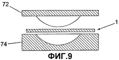
фиг.9 - продольный разрез формы, используемой в соединении с многослойной панелью согласно фиг.2;Fig.9 is a longitudinal section of a form used in connection with a multilayer panel according to Fig.2;
фиг.10 - многослойная панель согласно фиг.2 в сформированном состоянии.figure 10 - multilayer panel according to figure 2 in the formed state.
На фиг.1-3 показано защищающее тело устройство в виде защитного шлема 10. Шлем 10 сформирован с использованием панели 12, которая содержит первый материал или сердечник 20, который расположен между слоями второго материала или наружного слоя 30 и третьего материала или внутреннего слоя 50. Внутренний слой 30 и наружный слой 50 соединены каждый с сердечником с использованием клея 40.Figure 1-3 shows a body protecting device in the form of a
На фиг.3 показана многослойная панель 12 в изогнутом состоянии. В таком состоянии материал линейно изменяется от состояния с нулевым напряжением (относительно главных плоскостей панели 12) у нейтральной оси 14 до состояния максимального напряжения растяжения у внешней поверхности наружного слоя 30 и состояния максимального напряжения сжатия у внутренней поверхности внутреннего слоя 50. Эти напряжения растяжения и сжатия вызывают деформации растяжения и сжатия соответственно. Поэтому имеется скольжение между наружным слоем 30 и сердечником 20 и внутренним слоем 50 и сердечником 20, если это скольжение не предотвращается с помощью клея 40.Figure 3 shows a
Известная структура сердечника является сотовой или шестиугольной системой, которая показана на фиг.4. Каждая шестиугольная ячейка 60 имеет угол 62, 64 осевой симметрии, равный 60°, 120° и т.д., или другими словами n.60°, где n является целым числом. Поэтому ячейка не имеет угла осевой симметрии 90°, так что весь материал является не ортотропным. Кроме того, материал является антикластичным.A known core structure is a honeycomb or hexagonal system, which is shown in FIG. Each hexagonal cell 60 has an angle of axial symmetry of 62, 64, equal to 60 °, 120 °, etc., or in other words n.60 °, where n is an integer. Therefore, the cell does not have an angle of axial symmetry of 90 °, so that all the material is not orthotropic. In addition, the material is anticlastic.
Кроме того, сотовые ячейки 60 нельзя рассматривать в качестве соединительных колонн, поскольку каждая из шести боковых стенок каждой ячейки 60 используется совместно смежными ячейками.In addition, the cells 60 cannot be considered as connecting columns, since each of the six side walls of each cell 60 is shared by adjacent cells.
На фиг.5 показана матрица из ячеек для материала сердечника 20 согласно изобретению. Каждая ячейка содержит трубку 22. Трубки 22 расположены в тесно упакованной матрице, так что промежуток между смежными трубками является минимальным. Каждая трубка имеет диаметр 6 мм, толщину между 0,1 и 0,3 мм и длину около 35 мм. Это приводит к гибкости (отношение длины к диаметру) между 100 и 350 и коэффициенту формы (отношение диаметра к толщине) между 20 и 60. Следует отметить, что эти величины на один или два порядка превосходят системы согласно уровню техники.Figure 5 shows a matrix of cells for the
Использование этих геометрических величин, в частности используемой небольшой толщины, приводит к желательному режиму разрушения в виде прогрессивного продольного изгиба, даже когда для трубок используется полимерный материал. Неустойчивость, которая может приводить к режиму разрушения в виде полного продольного изгиба, предотвращается, поскольку трубки соединены со смежными трубками и окружены ими. Соединение с шестью другими трубками, которые распределены по окружности вокруг трубки, обеспечивает такую опору в любом направлении, перпендикулярном оси трубки. Поэтому ориентация каждой трубки (обычно параллельно оси прикладываемой нагрузки), по существу, сохраняется во время прогрессивного местного продольного изгиба за счет приложенной нагрузки.The use of these geometric values, in particular the small thickness used, leads to the desired fracture mode in the form of progressive longitudinal bending, even when a polymer material is used for the tubes. Instability, which can lead to a fracture mode in the form of a complete longitudinal bending, is prevented, since the tubes are connected to and surrounded by adjacent tubes. The connection with six other tubes, which are distributed around the circumference around the tube, provides such support in any direction perpendicular to the axis of the tube. Therefore, the orientation of each tube (usually parallel to the axis of the applied load) is essentially maintained during progressive local longitudinal bending due to the applied load.
Трубки можно соединять друг с другом с использованием клея. Другим подходящим способом является формирование трубок из внутреннего сердечника из первого материала или наружного сердечника из второго материала, при этом сердечники экструдируются совместно. Второй материал можно выбирать с более низкой температурой плавления, чем у первого материала. Обычно можно использовать разницу между 15 и 20°С. Во время формирования трубки можно нагревать до температуры между температурой плавления первого и второго материалов. Это приводит к сварке или сплавлению боковых стенок трубок. Этот способ обеспечивает более простое формирование и лучшую консистенцию во время формирования.The tubes can be connected to each other using glue. Another suitable method is the formation of tubes from the inner core of the first material or the outer core of the second material, while the cores are extruded together. The second material can be selected with a lower melting point than the first material. Typically, a difference of between 15 and 20 ° C can be used. During the formation of the tube can be heated to a temperature between the melting point of the first and second materials. This leads to welding or fusion of the side walls of the tubes. This method provides easier formation and better consistency during formation.
Следует отметить, что трубки не обязательно должны быть соединены друг с другом для обеспечения опоры друг на друга, или даже упираться друг в друга, если трубки расположены вблизи друг друга, так что они контактируют в ответ на небольшую деформацию.It should be noted that the tubes do not need to be connected to each other to support each other, or even abut against each other if the tubes are located close to each other, so that they are in contact in response to a slight deformation.
Эмпирически установлено, что устройство согласно изобретению эффективно обеспечивает поглощение более 80% энергии, что является значительным улучшением по сравнению с устройствами согласно уровню техники.It is empirically established that the device according to the invention effectively provides absorption of more than 80% of energy, which is a significant improvement compared to devices according to the prior art.
Поскольку каждая трубка 22 имеет бесконечный угол осевой симметрии, то вся трубчатая матрица приводит к созданию материала, который является, по существу, изотропным и не антикластичным. Трубки могут иметь поперечное сечение, отличающееся от круглого, и тем не менее обеспечивать близость боковой стенки каждой трубки к боковой стенке других трубок.Since each
На фиг.6 показана трубчатая матрица в изогнутом состоянии. Как указывалось выше, плоское напряжение и деформация у нейтральной оси 14 равны нулю, так что каждая трубка 22 сохраняет свою круговую форму, как показано на фиг. 7а. У внутренней поверхности 24 трубки 22 сжаты в направлении кривизны, и профили трубок в этом положении показаны в преувеличенном виде на фиг.7b. У наружной поверхности 26 трубки удлиняются в направлении кривизны, и профиль трубок в этом положении показан на фиг.7с.Figure 6 shows the tubular matrix in a bent state. As indicated above, the plane stress and strain at the
Следует отметить, что, несмотря на сжатие и удлинение трубок 22, профиль трубок 22 при усреднении по толщине материала 20 соответствует профилю у нейтральной оси 14. Кроме того, если имеется кривизна вокруг ортогональной оси, то это вызывает сжатие и удлинение в ортогональном направлении с тенденцией сохранения профиля трубок 22 в любой точке по толщине как у нейтральной оси 14, хотя диаметр трубок 22 уменьшается у внутренней поверхности 24 и увеличивается у наружной поверхности 26. В результате трубка является конической, что может даже улучшать способность структуры поглощать энергию.It should be noted that, despite the compression and elongation of the
Шлем формируют с использованием подходящего процесса термоформирования. Как показано на фиг.8, многослойную панель 12 нагревают с использованием нагревателей 70 до температуры между 155°С и 160°С, что превышает температуру плавления клея 40.The helmet is formed using a suitable thermoforming process. As shown in FIG. 8, the
Затем многослойную панель 12 переводят в форму, как показано на фиг.9. Выпуклая часть 72 формы обычно имеет резиновую контактную поверхность, а вогнутая часть 74 обычно выполнена из алюминия. Форма имеет температуру окружения, и перевод панели 12 необходимо осуществлять быстро, предпочтительно за менее чем 6 секунд, для минимизации охлаждения панели 12. Выпуклую часть 72 затем перемещают в направлении вогнутой части 74, так что панель 12 принимает форму формы.Then, the
Поскольку панель 12 была нагрета до температуры свыше температуры плавления клея, то может происходить скольжение между наружным слоем 30 и сердечником 20 и между внутренним слоем 50 и сердечником 20. Охлаждение панели 12 до температуры ниже 50° обеспечивает принятие панелью изогнутого профиля и соединение снова каждого из слоев 30, 50 с сердечником 20. Затем можно разъединять две части формы. Изогнутая панель 12 показана на фиг.10.Since the
Можно выполнять различные модификации и улучшения без выхода за объем данного изобретения. Например, трубки матрицы могут быть коническими с любым углом конусности.Various modifications and improvements can be made without departing from the scope of the present invention. For example, matrix tubes can be conical with any taper angle.
Claims (16)
Applications Claiming Priority (4)
| Application Number | Priority Date | Filing Date | Title |
|---|---|---|---|
| GB0329612A GB0329612D0 (en) | 2003-12-20 | 2003-12-20 | Safety helmet |
| GB0329612.6 | 2003-12-20 | ||
| GB0409065.0 | 2004-04-23 | ||
| GB0409065A GB0409065D0 (en) | 2004-04-23 | 2004-04-23 | Body protection device |
Related Child Applications (1)
| Application Number | Title | Priority Date | Filing Date |
|---|---|---|---|
| RU2010105087/12A Division RU2455912C2 (en) | 2003-12-20 | 2004-12-07 | Body protection device and method of its production |
Publications (2)
| Publication Number | Publication Date |
|---|---|
| RU2006126156A RU2006126156A (en) | 2008-01-27 |
| RU2390288C2 true RU2390288C2 (en) | 2010-05-27 |
Family
ID=34712702
Family Applications (2)
| Application Number | Title | Priority Date | Filing Date |
|---|---|---|---|
| RU2010105087/12A RU2455912C2 (en) | 2003-12-20 | 2004-12-07 | Body protection device and method of its production |
| RU2006126156/12A RU2390288C2 (en) | 2003-12-20 | 2004-12-07 | Body-protection device |
Family Applications Before (1)
| Application Number | Title | Priority Date | Filing Date |
|---|---|---|---|
| RU2010105087/12A RU2455912C2 (en) | 2003-12-20 | 2004-12-07 | Body protection device and method of its production |
Country Status (12)
| Country | Link |
|---|---|
| US (1) | US8082599B2 (en) |
| EP (2) | EP1694152B1 (en) |
| JP (2) | JP2007515568A (en) |
| AT (2) | ATE398940T1 (en) |
| AU (1) | AU2004304701B2 (en) |
| BR (1) | BRPI0417869A (en) |
| CA (1) | CA2552415C (en) |
| DE (1) | DE602004014638D1 (en) |
| ES (1) | ES2309590T3 (en) |
| MX (1) | MXPA06006800A (en) |
| RU (2) | RU2455912C2 (en) |
| WO (1) | WO2005060778A2 (en) |
Families Citing this family (53)
| Publication number | Priority date | Publication date | Assignee | Title |
|---|---|---|---|---|
| GB2431859A (en) * | 2005-10-31 | 2007-05-09 | Lloyd | A body protecting device comprising an array of energy absorbing cells |
| JP4555811B2 (en) * | 2006-10-31 | 2010-10-06 | 憲路 小山 | Hip protector |
| US8533869B1 (en) * | 2008-02-19 | 2013-09-17 | Noggin Group LLC | Energy absorbing helmet underwear |
| JP5611055B2 (en) * | 2009-01-13 | 2014-10-22 | 住ベテクノプラスチック株式会社 | Under cap |
| EP3254985B1 (en) | 2009-07-24 | 2021-04-21 | Dow Global Technologies LLC | A coated container device, method of making the same |
| RU2401622C1 (en) * | 2009-10-22 | 2010-10-20 | Учреждение Российской академии наук Государственный научный центр Российской Федерации-Институт медико-биологических проблем Российской академии наук (ГНЦ РФ-ИМБП РАН) | Therapeutic costume of axial load with automated control system |
| EP2507031B1 (en) | 2009-12-04 | 2018-03-28 | Union Carbide Chemicals & Plastics Technology LLC | Extruder screw system and process for producing an aqueous dispersion |
| US8235461B2 (en) * | 2010-01-21 | 2012-08-07 | Cohen Elie | Ventilated seat using shock absorbing material |
| FR2957552B1 (en) * | 2010-03-22 | 2014-05-23 | Latecoere | METHOD FOR MANUFACTURING A THERMALLY INSULATING WINDOW FOR AN ELECTRICAL WINDOW, IN PARTICULAR FOR AN AIRCRAFT, AND A REALIZED SEPARATION WINDOW |
| WO2012015624A1 (en) | 2010-07-27 | 2012-02-02 | Dow Global Technologies Llc | Low-density web and method of applying an additive composition thereto |
| US9420843B2 (en) | 2011-12-16 | 2016-08-23 | Oakwood Energy Management, Inc. | Rebounding cushioning helmet liner |
| US9462843B2 (en) | 2011-12-16 | 2016-10-11 | Viconic Defense Inc. | Cushioning helmet liner |
| US20140373256A1 (en) * | 2012-04-26 | 2014-12-25 | Philip R. Harris | Helmet pads |
| US9642410B2 (en) | 2013-02-06 | 2017-05-09 | Turtle Shell Protective Systems Llc | Helmet with external shock wave dampening panels |
| DE102013002344A1 (en) * | 2013-02-09 | 2014-08-14 | Dräger Safety AG & Co. KGaA | Protection device e.g. fire helmet used for protecting head of person, has outer shell that is aligned with inner wall to which object or head of person is aligned for partially covering object or head of person |
| US9573700B2 (en) * | 2013-07-31 | 2017-02-21 | Engineered Arresting Systems Corporation | Frangible components and their use in a system for energy absorption |
| US10736373B2 (en) | 2013-08-13 | 2020-08-11 | Smith Optics, Inc. | Helmet with shock absorbing inserts |
| USD752294S1 (en) | 2013-08-13 | 2016-03-22 | Smith Optics, Inc. | Helmet |
| USD795500S1 (en) | 2013-08-13 | 2017-08-22 | Smith Optics, Inc. | Helmet |
| USD752814S1 (en) | 2013-08-13 | 2016-03-29 | Smith Optics, Inc. | Helmet |
| GB2522049A (en) * | 2014-01-10 | 2015-07-15 | John George Lloyd | Body protection |
| US9415708B2 (en) | 2014-02-18 | 2016-08-16 | Oakwood Energy Management, Inc. | Conformable energy absorber |
| WO2015126794A1 (en) * | 2014-02-22 | 2015-08-27 | Arkusz Tomasz | Methods and apparatus for a head covering device with increased air circulation |
| US10631588B2 (en) | 2014-02-22 | 2020-04-28 | Tomasz Arkusz | Methods and apparatus for a head covering device with increased air circulation |
| KR101576364B1 (en) | 2014-03-27 | 2015-12-10 | 강릉원주대학교산학협력단 | Foldable helmet |
| USD773120S1 (en) | 2014-07-25 | 2016-11-29 | Smith Optics, Inc. | Helmet |
| US9408423B2 (en) * | 2014-09-25 | 2016-08-09 | David A. Guerra | Impact reducing sport equipment |
| GB2534887B (en) * | 2015-02-03 | 2017-03-29 | George Lloyd John | Protective eyewear |
| GB201501834D0 (en) | 2015-02-04 | 2015-03-18 | Isis Innovation | An impact absorbing structure |
| US20160242485A1 (en) * | 2015-02-25 | 2016-08-25 | Steven Christopher CARTON | Helmet |
| WO2016149523A2 (en) * | 2015-03-17 | 2016-09-22 | Major League Baseball | Protective headgear for sports participants, especially baseball fielders |
| US11089832B2 (en) | 2015-05-01 | 2021-08-17 | Gentex Corporation | Helmet impact attenuation article |
| RU2614959C2 (en) * | 2015-05-05 | 2017-03-31 | Федеральное государственное бюджетное образовательное учреждение высшего профессионального образования "Тольяттинский государственный университет" (ТГУ) | Glue-welding method for joining substrates |
| JP6184568B1 (en) * | 2016-08-24 | 2017-08-23 | 宇都宮 哲 | Knee cushion body and supporter with this cushion body |
| US10736371B2 (en) | 2016-10-01 | 2020-08-11 | Choon Kee Lee | Mechanical-waves attenuating protective headgear |
| US11147334B2 (en) * | 2016-10-07 | 2021-10-19 | William STECK | Apparatus and method for improving impact performance of helmets |
| USD822905S1 (en) | 2016-10-31 | 2018-07-10 | Smith Optics, Inc. | Helmet |
| USD817553S1 (en) | 2016-10-31 | 2018-05-08 | Smith Optics, Inc. | Helmet |
| US11134738B2 (en) | 2017-10-25 | 2021-10-05 | Turtle Shell Protective Systems Llc | Helmet with external flexible cage |
| US10433610B2 (en) * | 2017-11-16 | 2019-10-08 | Choon Kee Lee | Mechanical-waves attenuating protective headgear |
| US10561189B2 (en) | 2017-12-06 | 2020-02-18 | Choon Kee Lee | Protective headgear |
| SE1751565A1 (en) * | 2017-12-18 | 2019-06-19 | Svein Kleiven | Protective device |
| USD892446S1 (en) * | 2018-06-14 | 2020-08-11 | Adidas Ag | Swimming cap |
| KR20200122605A (en) * | 2019-04-18 | 2020-10-28 | 현대자동차주식회사 | Exterior panel of automobile |
| IT201900014499A1 (en) * | 2019-08-09 | 2021-02-09 | Eurofoam S R L | PROCESS FOR MAKING A PROFILE COVERING AND PROFILE COVERING MADE ACCORDING TO THIS PROCEDURE |
| US10869520B1 (en) * | 2019-11-07 | 2020-12-22 | Lionhead Helmet Intellectual Properties, Lp | Helmet |
| EP3838042B1 (en) | 2019-12-18 | 2022-06-08 | George TFE SCP | Helmet |
| EP3838043B1 (en) | 2019-12-18 | 2023-08-16 | George TFE SCP | Helmet |
| EP3900914B1 (en) | 2020-04-24 | 2022-06-08 | George TFE SCP | Thermoforming apparatus and process |
| US11547166B1 (en) | 2022-02-11 | 2023-01-10 | Lionhead Helmet Intellectual Properties, Lp | Helmet |
| US11641904B1 (en) | 2022-11-09 | 2023-05-09 | Lionhead Helmet Intellectual Properties, Lp | Helmet |
| GB2628575A (en) * | 2023-03-29 | 2024-10-02 | Stirling Moulded Composites Ltd | Forming apparatus and method |
| US12121095B1 (en) | 2024-04-24 | 2024-10-22 | Lionhead Helmet Intellectual Properties, Lp | Helmet |
Citations (3)
| Publication number | Priority date | Publication date | Assignee | Title |
|---|---|---|---|---|
| US2477852A (en) * | 1945-07-04 | 1949-08-02 | Owens Corning Fiberglass Corp | Structural panel construction |
| US3829900A (en) * | 1973-08-30 | 1974-08-20 | Mine Safety Appliances Co | Safety hat energy absorbing liner |
| EP0047712A2 (en) * | 1980-09-08 | 1982-03-17 | Figgie International Inc. | Shock attenuation system for headgear |
Family Cites Families (37)
| Publication number | Priority date | Publication date | Assignee | Title |
|---|---|---|---|---|
| US3447163A (en) * | 1966-02-16 | 1969-06-03 | Peter W Bothwell | Safety helmets |
| US3811130A (en) * | 1970-11-13 | 1974-05-21 | C Townsend | Headwear construction |
| JPS50111367U (en) * | 1974-02-26 | 1975-09-11 | ||
| US3877076A (en) * | 1974-05-08 | 1975-04-15 | Mine Safety Appliances Co | Safety hat energy absorbing liner |
| FR2370448A2 (en) | 1976-11-10 | 1978-06-09 | Coignac Pierre | Rigid cap for safety helmet - has core consisting of honeycomb of cells separated by intermediate walls |
| JPS56118816A (en) * | 1980-02-26 | 1981-09-18 | Toagosei Chem Ind Co Ltd | Manufacture of molded laminate for automobile ceiling |
| US4484364A (en) * | 1980-09-08 | 1984-11-27 | A-T-O Inc. | Shock attenuation system for headgear |
| DE3035265A1 (en) * | 1980-09-18 | 1982-04-29 | AOE Plastic GmbH, 8000 München | SAFETY HELMET |
| US4558470A (en) * | 1982-10-26 | 1985-12-17 | Figgie International Inc. | Shock attenuation system |
| US4534068A (en) * | 1982-10-26 | 1985-08-13 | Figgie International Inc. | Shock attenuation system |
| JPS5991108U (en) * | 1982-12-10 | 1984-06-20 | 株式会社村井 | Moisture wicking reinforcement and weight reduction device mainly for the inside and outside of shoes |
| FR2542668B1 (en) * | 1983-03-15 | 1986-06-20 | Claude Morin | PROCESS FOR PRODUCING A CURVED SURFACE ELEMENT FROM A RIGID BOARD OF A MATERIAL OF THE "HONEYCOMB" TYPE AND PRODUCT OBTAINED |
| DE3336417A1 (en) * | 1983-10-06 | 1985-04-18 | Kufner Textilwerke GmbH, 8000 München | HOT SEAL ADHESIVE FOR COATING SURFACES, ESPECIALLY INSERTS, AND METHOD FOR THE PRODUCTION THEREOF |
| US4627114A (en) * | 1984-08-23 | 1986-12-09 | Figgie International, Inc. | Shock attenuation structure |
| JPS61125129U (en) * | 1985-01-24 | 1986-08-06 | ||
| SU1313411A1 (en) * | 1986-01-07 | 1987-05-30 | Московский Технологический Институт Легкой Промышленности | Method of making a garment part |
| JPH01171849A (en) * | 1987-12-27 | 1989-07-06 | Yoshidatsukasa Kk | Planar composite material |
| JP2669513B2 (en) * | 1991-11-01 | 1997-10-29 | 河西工業株式会社 | Manufacturing method of automobile interior parts |
| US5349893A (en) * | 1992-02-20 | 1994-09-27 | Dunn Eric S | Impact absorbing armor |
| GB9213704D0 (en) | 1992-06-27 | 1992-08-12 | Brine C A | Safety helmet |
| DE4329297A1 (en) * | 1993-08-31 | 1995-03-02 | Gerhard Sperber | Bicycle crash helmet |
| JPH06297617A (en) * | 1993-04-14 | 1994-10-25 | Sutoriito Design Shiya:Kk | Fiber-containing honeycomb structural material and production thereof |
| DE4314861A1 (en) * | 1993-05-05 | 1994-11-10 | Tubus Bauer Gmbh | Process for producing a honeycomb body and honeycomb body |
| TW274068B (en) * | 1993-05-13 | 1996-04-11 | Ciba Geigy Ag | |
| JPH07331522A (en) * | 1994-06-03 | 1995-12-19 | Takashizu Iwashimizu | Helmet comprising shell unit in plural layers |
| DE19528251A1 (en) * | 1995-08-01 | 1997-02-06 | Huels Chemische Werke Ag | Lightweight board |
| JPH09325000A (en) * | 1996-06-04 | 1997-12-16 | Opt:Kk | Human body protecting material |
| EP0881064A3 (en) | 1997-05-29 | 2000-12-13 | Trauma-Lite Limited | Protective element |
| US6336220B1 (en) * | 1997-05-29 | 2002-01-08 | Trauma-Lite Limited | Protective element |
| JPH1136130A (en) * | 1997-07-14 | 1999-02-09 | Takatsugu Oizumi | Safety helmet |
| US5918309A (en) * | 1997-10-14 | 1999-07-06 | Second Chance Body Armor, Inc. | Blunt force resistant structure for a protective garment |
| JP3025480B2 (en) * | 1998-07-29 | 2000-03-27 | 株式会社デサント | Shock absorbing clothing material |
| JP3000275B1 (en) * | 1998-09-08 | 2000-01-17 | 株式会社デサント | Riding protector |
| JP2001248010A (en) * | 2000-03-02 | 2001-09-14 | Takatsugu Oizumi | Air-permeable helmet using multiple laminate material |
| GB0122328D0 (en) * | 2001-09-15 | 2001-11-07 | Sportsfactory Consulting Ltd | Protective body armour |
| JP3096735U (en) * | 2003-03-27 | 2003-10-03 | 文章 呉 | Bamboo tube ring sandwich plate |
| US7089602B2 (en) * | 2003-06-30 | 2006-08-15 | Srikrishna Talluri | Multi-layered, impact absorbing, modular helmet |
-
2004
- 2004-12-07 EP EP04805969A patent/EP1694152B1/en not_active Expired - Lifetime
- 2004-12-07 AT AT04805969T patent/ATE398940T1/en not_active IP Right Cessation
- 2004-12-07 JP JP2006544538A patent/JP2007515568A/en active Pending
- 2004-12-07 ES ES04805969T patent/ES2309590T3/en not_active Expired - Lifetime
- 2004-12-07 RU RU2010105087/12A patent/RU2455912C2/en active
- 2004-12-07 CA CA2552415A patent/CA2552415C/en not_active Expired - Lifetime
- 2004-12-07 AU AU2004304701A patent/AU2004304701B2/en not_active Ceased
- 2004-12-07 WO PCT/GB2004/005149 patent/WO2005060778A2/en not_active Ceased
- 2004-12-07 RU RU2006126156/12A patent/RU2390288C2/en active
- 2004-12-07 AT AT06024091T patent/ATE519391T1/en not_active IP Right Cessation
- 2004-12-07 MX MXPA06006800A patent/MXPA06006800A/en active IP Right Grant
- 2004-12-07 BR BRPI0417869-6A patent/BRPI0417869A/en not_active Application Discontinuation
- 2004-12-07 EP EP06024091A patent/EP1762150B1/en not_active Expired - Lifetime
- 2004-12-07 DE DE602004014638T patent/DE602004014638D1/en not_active Expired - Lifetime
- 2004-12-07 US US10/583,343 patent/US8082599B2/en active Active
-
2011
- 2011-02-24 JP JP2011038389A patent/JP2011137282A/en active Pending
Patent Citations (3)
| Publication number | Priority date | Publication date | Assignee | Title |
|---|---|---|---|---|
| US2477852A (en) * | 1945-07-04 | 1949-08-02 | Owens Corning Fiberglass Corp | Structural panel construction |
| US3829900A (en) * | 1973-08-30 | 1974-08-20 | Mine Safety Appliances Co | Safety hat energy absorbing liner |
| EP0047712A2 (en) * | 1980-09-08 | 1982-03-17 | Figgie International Inc. | Shock attenuation system for headgear |
Also Published As
| Publication number | Publication date |
|---|---|
| CA2552415C (en) | 2014-12-30 |
| ATE519391T1 (en) | 2011-08-15 |
| BRPI0417869A (en) | 2007-04-27 |
| EP1694152B1 (en) | 2008-06-25 |
| ES2309590T3 (en) | 2008-12-16 |
| EP1694152A2 (en) | 2006-08-30 |
| HK1091104A1 (en) | 2007-01-12 |
| EP1762150A3 (en) | 2007-12-05 |
| AU2004304701A1 (en) | 2005-07-07 |
| ATE398940T1 (en) | 2008-07-15 |
| RU2455912C2 (en) | 2012-07-20 |
| EP1762150A2 (en) | 2007-03-14 |
| US8082599B2 (en) | 2011-12-27 |
| JP2007515568A (en) | 2007-06-14 |
| AU2004304701B2 (en) | 2011-07-07 |
| RU2006126156A (en) | 2008-01-27 |
| MXPA06006800A (en) | 2006-12-19 |
| JP2011137282A (en) | 2011-07-14 |
| US20080120764A1 (en) | 2008-05-29 |
| CA2552415A1 (en) | 2005-07-07 |
| WO2005060778A3 (en) | 2005-09-15 |
| WO2005060778A2 (en) | 2005-07-07 |
| RU2010105087A (en) | 2011-08-20 |
| DE602004014638D1 (en) | 2008-08-07 |
| EP1762150B1 (en) | 2011-08-10 |
Similar Documents
| Publication | Publication Date | Title |
|---|---|---|
| RU2390288C2 (en) | Body-protection device | |
| US11298913B2 (en) | Energy-absorbing structure with defined multi-phasic crush properties | |
| US5264259A (en) | Energy absorbing structure | |
| KR102043399B1 (en) | Interdigitated cellular cushioning | |
| US20180058531A1 (en) | Energy absorbing truss structures for mitigation of injuries from blasts and impacts | |
| JPH05332386A (en) | Energy absorbing member | |
| US20080307568A1 (en) | Body Protecting Device | |
| US20160160952A1 (en) | Energy absorbing truss structures for mitigation of injuries from blasts and impacts | |
| CN101564212B (en) | Body protecting device and method for forming body protecting device | |
| CN110198869A (en) | Shock absorbing systems for motor vehicles | |
| JP3456596B2 (en) | Energy absorbing member | |
| US6715593B1 (en) | Crush tube assembly | |
| JP2014218179A (en) | Energy absorption member | |
| HK1095711A (en) | Body protecting device | |
| HK1091104B (en) | Body protecting device | |
| JP7376295B2 (en) | Fiber-reinforced resin composite material and method for producing fiber-reinforced resin composite material | |
| JP2892854B2 (en) | Energy absorbing material | |
| JP3007744B2 (en) | Energy absorbing material | |
| JP7812665B2 (en) | Body structural members | |
| JP2006046481A (en) | Method for manufacturing shock absorbing member | |
| JP2023122707A (en) | Body structural member and body structure | |
| WO2025057390A1 (en) | Vehicle body pillar structure and vehicle body side structure |