RU2334359C1 - Lightwave communication system - Google Patents
Lightwave communication system Download PDFInfo
- Publication number
- RU2334359C1 RU2334359C1 RU2006139123/09A RU2006139123A RU2334359C1 RU 2334359 C1 RU2334359 C1 RU 2334359C1 RU 2006139123/09 A RU2006139123/09 A RU 2006139123/09A RU 2006139123 A RU2006139123 A RU 2006139123A RU 2334359 C1 RU2334359 C1 RU 2334359C1
- Authority
- RU
- Russia
- Prior art keywords
- communication system
- paths
- matrix
- nodes
- communication nodes
- Prior art date
Links
Images


Landscapes
- Optical Communication System (AREA)
Abstract
Description
Изобретение относится к оптическим системам связи и может быть использовано при создании и совершенствовании таких систем.The invention relates to optical communication systems and can be used to create and improve such systems.
Известен способ построения системы оптической связи (см., например, Шмалько А.В. Цифровые сети связи: основы планирования и построения. - М.: ЭКО-ТРЕНДЗ, 2001, с.189-194; Убайдулаев P.P. Волоконно-оптические сети. - М.: ЭКО-ТРЕНДЗ, 2001, с.96-101).A known method of constructing an optical communication system (see, for example, Shmalko A.V. Digital communication networks: the basics of planning and construction. - M .: EKO-TRENDZ, 2001, p. 189-194; Ubaidulaev PP Fiber optic networks. - M .: ECO-TRENDZ, 2001, p.96-101).
В данном способе на каждом узле связи устанавливают мультиплексоры ввода-вывода, которые соединяют волоконно-оптическими линиями связи.In this method, I / O multiplexers are installed on each communication node, which are connected by fiber-optic communication lines.
Недостатком указанного способа является сложность технической реализации системы оптической связи вследствие необходимости преобразования информационных сигналов из электрической формы в оптическую и обратно.The disadvantage of this method is the complexity of the technical implementation of the optical communication system due to the need to convert information signals from electrical form to optical and vice versa.
Известен также способ построения системы оптической связи (см., например, Фриман Р. Волоконно-оптические системы связи. - М.: Техносфера, 2006, с.407-411, 425-428), заключающийся в установке на узлах связи аппаратуры оптической коммутации, мультиплексирования, усиления и соединении их волоконно-оптическими линиями связи.There is also a method of constructing an optical communication system (see, for example, Freeman R. Fiber-optic communication systems. - M .: Tekhnosfera, 2006, p.407-411, 425-428), which consists in installing optical switching equipment on communication nodes , multiplexing, amplifying and connecting them with fiber optic communication lines.
Недостатком указанного способа является низкая пропускная способность системы оптической связи ввиду передачи каждого оптического сигнала по отдельному оптическому волокну.The disadvantage of this method is the low bandwidth of the optical communication system due to the transmission of each optical signal through a separate optical fiber.
Наиболее близким по своей технической сущности к заявляемому способу построения системы оптической связи является способ построения по патенту CN №1284804 от 21.02.2001, МПК 7 Н04В 10/02 (приоритетная заявка GB 1999016577 от 1999.07.15).Closest in its technical essence to the claimed method for constructing an optical communication system is a method for constructing according to patent CN No. 1284804 of 02.21.2001, IPC 7 Н04В 10/02 (priority application GB 1999016577 of 1999.07.15).
Способ-прототип заключается в том, что на передающем конце узла связи устанавливают множество источников света и терминалы спектрального уплотнения, а на его приемном конце - множество фотодетекторов и терминалы спектрального уплотнения.The prototype method consists in the fact that at the transmitting end of the communication node, a plurality of light sources and spectral compression terminals are installed, and at its receiving end, a plurality of photodetectors and spectral compression terminals are installed.
Данный способ построения позволяет увеличить пропускную способность системы оптической связи за счет передачи нескольких оптических сигналов по одному оптическому волокну.This method of construction allows you to increase the throughput of the optical communication system by transmitting multiple optical signals over a single optical fiber.
Недостатком способа-прототипа является то, что на его реализацию с заданной пропускной способностью требуются относительно высокие материальные затраты, что обусловлено необходимостью использования дополнительных функциональных устройств на каждом узле системы оптической связи.The disadvantage of the prototype method is that its implementation with a given throughput requires relatively high material costs, due to the need to use additional functional devices at each node of the optical communication system.
Целью заявленного изобретения является разработка способа построения системы оптической связи, обеспечивающего сокращение материальных затрат на его реализацию, при сохранении заданной пропускной способности.The aim of the claimed invention is to develop a method for constructing an optical communication system that provides a reduction in material costs for its implementation, while maintaining a given throughput.
Заявленный способ расширяет арсенал средств данного назначения.The claimed method extends the arsenal of funds for this purpose.
Поставленная цель достигается тем, что в известном способе построения системы оптической связи, содержащей N≥2 узлов связи, объединенных М≥1 ребрами оптических трактов (РОТ), заключающемся в том, что на передающем конце узла связи устанавливают множество источников света и терминалы спектрального уплотнения, а на его приемном конце - множество фотодетекторов и терминалы спектрального уплотнения, предварительно выделяют в системе оптической связи пары Zi,j корреспондирующих узлов связи, где i=1,2,..., N, j=1,2,..., N, i≠j. Задают предельно допустимое значение ранга rдоп пути между любой парой корреспондирующих узлов связи и минимально допустимое число Smin путей, проходящих через РОТ между соответствующими парами Zi,j корреспондирующих узлов связи. Выделяют K РОТ, по каждому из которых общее число Sk, где k=1,2,...,K, проходящих путей между парами Zi,j корреспондирующих узлов связи превышает Smin. Для чего формируют структурную матрицу системы оптической связи ![]()
![]()
![]()
![]()
![]()
![]()
![]()
![]()
![]()
![]()
![]()
![]()
между всеми парами Zi,j корреспондирующих узлов связи. Причем элементы матрицы путей ![]()
![]()
![]()
![]()
Благодаря новой совокупности существенных признаков в проектируемой системе оптической связи установка источников света, фотодетекторов и терминалов спектрального уплотнения осуществляется только на наиболее загруженных участках. В то же время на менее загруженных участках установка указанных устройств не производится, что не снижает общей пропускной способности системы оптической связи. То есть для реализации системы оптической связи в сравнении с прототипом требуется меньшее число дополнительных элементов, что снижает общие материальные затраты и определяет возможность реализации заявленного технического результата.Thanks to a new set of essential features in the designed optical communication system, the installation of light sources, photodetectors and spectral compaction terminals is carried out only in the busiest areas. At the same time, installation of these devices is not performed on less busy areas, which does not reduce the overall throughput of the optical communication system. That is, to implement an optical communication system in comparison with the prototype requires a smaller number of additional elements, which reduces the overall material costs and determines the feasibility of the claimed technical result.
Проведенный анализ уровня техники позволил установить, что аналоги, характеризующиеся совокупностью признаков, тождественных всем признакам заявленного технического решения, отсутствуют, что указывает на соответствие заявленного способа условию патентоспособности "новизна".The analysis of the prior art made it possible to establish that analogues that are characterized by a combination of features that are identical to all the features of the claimed technical solution are absent, which indicates the compliance of the claimed method with the condition of patentability "novelty".
Результаты поиска известных решений в данной и смежных областях техники с целью выявления признаков, совпадающих с отличительными от прототипа признаками заявленного объекта, показали, что они не следуют явным образом из уровня техники. Из уровня техники также не выявлена известность отличительных существенных признаков, обусловливающих тот же технический результат, который достигнут в заявляемом способе. Следовательно, заявленное изобретение соответствует условию патентоспособности "изобретательский уровень".Search results for known solutions in this and related fields of technology in order to identify features that match the distinctive features of the claimed object from the prototype showed that they do not follow explicitly from the prior art. The prior art also did not reveal the fame of the distinctive essential features that determine the same technical result that is achieved in the claimed method. Therefore, the claimed invention meets the condition of patentability "inventive step".
Заявленный способ поясняется чертежами, на которых показано:The claimed method is illustrated by drawings, which show:
фиг.1 - общая структурная схема системы оптической связи;figure 1 is a General structural diagram of an optical communication system;
фиг.2 - состав и соединение оборудования на узлах связи, инцидентных ребру, по которому общее число проходящих путей между парами корреспондирующих узлов связи превышает минимально допустимое значение;figure 2 - the composition and connection of equipment at the communication nodes incidental to the rib along which the total number of passing paths between pairs of corresponding communication nodes exceeds the minimum acceptable value;
фиг.3 - функциональная схема системы оптической связи;figure 3 is a functional diagram of an optical communication system;
фиг.4 - структура фрагмента системы оптической связи, представляемая в виде графа;figure 4 - structure of a fragment of the optical communication system, presented in the form of a graph;
фиг.5 - совокупность путей между парами корреспондирующих узлов системы оптической связи;5 is a set of paths between pairs of corresponding nodes of the optical communication system;
фиг.6 - выделенное РОТ, по которому общее число путей между парами корреспондирующих узлов связи превышает минимально допустимое значение.6 is a dedicated MOUTH, in which the total number of paths between pairs of corresponding communication nodes exceeds the minimum acceptable value.
Реализация заявленного способа объясняется следующим образом.The implementation of the claimed method is explained as follows.
В общем случае для построения системы оптической связи используют множество источников света, фотодетекторов и терминалы спектрального уплотнения, что повышает пропускную способность системы связи. С другой стороны, применение данного способа построения приводит к необоснованным материальным затратам. Следовательно, требуется разработать способ построения системы оптической связи, который позволит снизить экономические затраты на его реализацию и в то же время обеспечить заданную пропускную способность системы оптической связи на требуемом уровне, что и предлагается в заявленном решении.In general, a plurality of light sources, photodetectors and spectral densification terminals are used to construct an optical communication system, which increases the throughput of the communication system. On the other hand, the use of this method of construction leads to unreasonable material costs. Therefore, it is required to develop a method for constructing an optical communication system, which will reduce the economic costs of its implementation and at the same time provide a given throughput of the optical communication system at the required level, which is proposed in the claimed solution.
Реализация заявляемого способа рассмотрена на примере системы оптической связи, показанной на фиг.1. Система оптической связи состоит из узлов связи 1, 2, 3, 4, соединенных соответствующими им инцидентными ребрами. В общем случае на каждом узле системы оптической связи (например, на 2-м и 3-м узлах) установлены (фиг.2):The implementation of the proposed method is considered on the example of the optical communication system shown in figure 1. The optical communication system consists of
- мультиплексоры ввода-вывода 2.1', 2.1" и 3.1', 3.1";- I / O multiplexers 2.1 ', 2.1 "and 3.1', 3.1";
- источники света 2.2', 2.2" и 3.2', 3.2";- light sources 2.2 ', 2.2 "and 3.2', 3.2";
- фото детекторы 2.3', 2.3" и 3.3', 3.3";- photo detectors 2.3 ', 2.3 "and 3.3', 3.3";
- терминалы спектрального уплотнения 2.4 и 3.4.- spectral multiplexing terminals 2.4 and 3.4.
Выходы мультиплексоров ввода-вывода 2.1', 2.1", 3.1', 3.1" соединены с входами соответствующих источников света 2.2', 2.2", 3.2', 3.2" и выходами фотодетекторов 2.3', 2.3", 3.3', 3.3". Выходы источников света 2.2', 2.2", 3.2', 3.2" и входы фотодетекторов 2.3', 2.3", 3.3', 3.3" соединены с входами соответствующих терминалов спектрального уплотнения 2.4, 3.4, выходы которых соединены с волокном оптического кабеля 6.The outputs of the input / output multiplexers 2.1 ', 2.1 ", 3.1', 3.1" are connected to the inputs of the corresponding light sources 2.2 ', 2.2 ", 3.2', 3.2" and the outputs of the photodetectors 2.3 ', 2.3 ", 3.3', 3.3". The outputs of the light sources 2.2 ', 2.2 ", 3.2', 3.2" and the inputs of the photodetectors 2.3 ', 2.3 ", 3.3', 3.3" are connected to the inputs of the respective terminals of the spectral seal 2.4, 3.4, the outputs of which are connected to the fiber of the
Функционально система оптической связи состоит из двух колец (фиг.3), в каждом из которых осуществляется передача синхронных сигналов и каждое из которых содержит соответствующие мультиплексоры ввода-вывода 1.1, 2.1', 3.1' и 2.1", 3.1", 4.1, соединенные волокнами оптического кабеля 6. Мультиплексоры ввода-вывода 1.1, 4.1 и пары мультиплексоров ввода-вывода 2.1'-2.1", 3.1'-3.1" расположены на соответствующих узлах связи 1,4,2,3 и в каждой паре соединены между собой линиями внутреннего монтажа 5.Functionally, the optical communication system consists of two rings (Fig. 3), in each of which synchronous signals are transmitted and each of which contains the corresponding input-output multiplexers 1.1, 2.1 ', 3.1' and 2.1 ", 3.1", 4.1, connected by fibers
Порядок реализации заявленного способа рассмотрен на примере системы оптической связи с числом узлов N=4 и ребер М=5, показанной на фиг.4. В системе оптической связи предварительно выделяют пары корреспондирующих узлов связи. В рассматриваемом примере условно приняты пары Z1,3 и Z2,3. Задают предварительно минимально допустимое число Smin путей, проходящих через РОТ между парами Z1,3 и Z2,3 корреспондирующих узлов связи, например Smin=2. Также предварительно задают предельно допустимое значение ранга rдоп пути между любой парой корреспондирующих узлов, например rдоп=2. Ранг пути - это число ребер системы связи, входящих в данный путь. Например, ранг пути между парой узлов Z1,3 составляет r=1 или r=2 (см. фиг.5а). Величина ранга пути определяется требованиями по качеству организуемых каналов в системе связи (см., например, Давыдов Г.Б., Рогинский В.Н., Толчан А.Я. Сети электросвязи. М.: Связь, 1977, С.139).The implementation order of the inventive method is considered on the example of an optical communication system with the number of nodes N = 4 and ribs M = 5, shown in figure 4. In an optical communication system, pairs of corresponding communication nodes are preliminarily isolated. In this example, the pairs Z 1,3 and Z 2,3 are conditionally accepted. Pre-set the minimum acceptable number S min of paths passing through the MOUTH between the pairs Z 1,3 and Z 2,3 corresponding to the communication nodes, for example S min = 2. Also, the maximum permissible value of the rank r of the additional path between any pair of corresponding nodes is preliminarily set, for example, r additional = 2. The rank of the path is the number of edges of the communication system included in this path. For example, the rank of the path between a pair of nodes Z 1,3 is r = 1 or r = 2 (see figa). The value of the rank of the path is determined by the requirements for the quality of the channels being organized in the communication system (see, for example, Davydov GB, Roginsky VN, Tolchan A.Ya. Telecommunication networks. M: Communication, 1977, P.139).
Затем из всей совокупности РОТ выделяют те из них, по которым общее число проходящих путей Sk≥Smin. Для чего формируют структурную матрицу системы оптической связи ![]()
![]()

В матрице ![]()
![]()
По сформированной структурной матрице системы оптической связи ![]()
![]()
С этой целью структурную матрицу ![]()
![]()
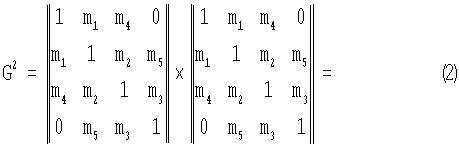

где знак ∨ - означает операцию логического сложения.where the sign ∨ - means the operation of logical addition.
В возведенной в степень rдоп=2 структурной матрице ![]()
![]()
Затем формируют матрицу путей ![]()
![]()
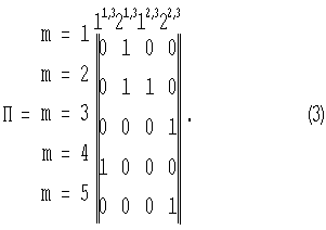
В матрице ![]()
![]()
![]()
![]()
![]()
![]()
![]()
![]()
Из сформированной матрицы путей ![]()
![]()
Таким образом, в результате выполненных действий было выделено РОТ, по которому общее число проходящих путей между парами Z1,3 и Z2,3 корреспондирующих узлов связи превышает Smin=1.Thus, as a result of the performed actions, a POT was allocated, according to which the total number of passing paths between pairs Z 1,3 and Z 2,3 of corresponding communication nodes exceeds S min = 1.
Следовательно, целесообразно на узлах связи с номерами 2 и 3, инцидентных ребру с номером 2 (фиг.2), установить источники света 2.2', 2.2", 3.2', 3.2", фотодетекторы 2.3', 2.3", 3.3', 3.3" и терминалы спектрального уплотнения 2.4, 3.4.Therefore, it is advisable to establish light sources 2.2 ', 2.2 ", 3.2', 3.2", photo detectors 2.3 ', 2.3 ", 3.3', 3.3" at the communication nodes with
В случае использования способа-прототипа с четырьмя узлами необходимо на каждом узле связи разместить дополнительно по одному источнику света, фотодетектору и терминалу спектрального уплотнения, то есть всего 12 устройств. В заявленном решении установка указанных функциональных устройств осуществляется только на узлах, инцидентных выделенному ребру, т.е. всего 6.In the case of using the prototype method with four nodes, it is necessary to place an additional one light source, a photodetector and a spectral densification terminal on each communication node, that is, a total of 12 devices. In the claimed solution, the installation of these functional devices is carried out only on the nodes incident to the selected edge, i.e. only 6.
Из рассмотренного примера можно заключить, что при использовании системы оптической связи с числом узлов N=4 обеспечивается практически двукратное снижение количества дополнительно устанавливаемых функциональных устройств при одновременном сохранении пропускной способности системы оптической связи, что при построении заявленным способом системы оптической связи с числом узлов N=10-20, выигрыш по количеству дополнительных функциональных устройств будет составлять 10 и более раз.From the considered example, we can conclude that when using an optical communication system with the number of nodes N = 4, an almost twofold decrease in the number of additionally installed functional devices is ensured while preserving the throughput of the optical communication system, which when constructing an optical communication system with the number of nodes N = 10 by the claimed method -20, the gain in the number of additional functional devices will be 10 or more times.
Отмеченное указывает на возможность достижения сформулированного технического результата при использовании заявленного технического решения.The aforementioned indicates the possibility of achieving the formulated technical result when using the claimed technical solution.
Claims (1)
Priority Applications (1)
| Application Number | Priority Date | Filing Date | Title |
|---|---|---|---|
| RU2006139123/09A RU2334359C1 (en) | 2006-11-07 | 2006-11-07 | Lightwave communication system |
Applications Claiming Priority (1)
| Application Number | Priority Date | Filing Date | Title |
|---|---|---|---|
| RU2006139123/09A RU2334359C1 (en) | 2006-11-07 | 2006-11-07 | Lightwave communication system |
Publications (2)
| Publication Number | Publication Date |
|---|---|
| RU2006139123A RU2006139123A (en) | 2008-05-20 |
| RU2334359C1 true RU2334359C1 (en) | 2008-09-20 |
Family
ID=39798333
Family Applications (1)
| Application Number | Title | Priority Date | Filing Date |
|---|---|---|---|
| RU2006139123/09A RU2334359C1 (en) | 2006-11-07 | 2006-11-07 | Lightwave communication system |
Country Status (1)
| Country | Link |
|---|---|
| RU (1) | RU2334359C1 (en) |
Cited By (1)
| Publication number | Priority date | Publication date | Assignee | Title |
|---|---|---|---|---|
| RU2472293C1 (en) * | 2011-07-29 | 2013-01-10 | Государственное казенное образовательное учреждение высшего профессионального образования Академия Федеральной службы охраны Российской Федерации (Академия ФСО России) | Method of non-blocked routing |
Citations (4)
| Publication number | Priority date | Publication date | Assignee | Title |
|---|---|---|---|---|
| US5287384A (en) * | 1992-10-15 | 1994-02-15 | Lxe Inc. | Frequency hopping spread spectrum data communications system |
| US6046832A (en) * | 1997-12-04 | 2000-04-04 | Fishman; Ilya M. | System and method for protection of WDM/SONET networks |
| CN1284804A (en) * | 1999-07-15 | 2001-02-21 | 马科尼通讯有限公司 | Communication system |
| RU2201034C2 (en) * | 1997-09-17 | 2003-03-20 | Телефонактиеболагет Лм Эрикссон (Пабл) | Uncoordinated multiple-user frequency-jump wireless pico-cell system |
-
2006
- 2006-11-07 RU RU2006139123/09A patent/RU2334359C1/en not_active IP Right Cessation
Patent Citations (4)
| Publication number | Priority date | Publication date | Assignee | Title |
|---|---|---|---|---|
| US5287384A (en) * | 1992-10-15 | 1994-02-15 | Lxe Inc. | Frequency hopping spread spectrum data communications system |
| RU2201034C2 (en) * | 1997-09-17 | 2003-03-20 | Телефонактиеболагет Лм Эрикссон (Пабл) | Uncoordinated multiple-user frequency-jump wireless pico-cell system |
| US6046832A (en) * | 1997-12-04 | 2000-04-04 | Fishman; Ilya M. | System and method for protection of WDM/SONET networks |
| CN1284804A (en) * | 1999-07-15 | 2001-02-21 | 马科尼通讯有限公司 | Communication system |
Cited By (1)
| Publication number | Priority date | Publication date | Assignee | Title |
|---|---|---|---|---|
| RU2472293C1 (en) * | 2011-07-29 | 2013-01-10 | Государственное казенное образовательное учреждение высшего профессионального образования Академия Федеральной службы охраны Российской Федерации (Академия ФСО России) | Method of non-blocked routing |
Also Published As
| Publication number | Publication date |
|---|---|
| RU2006139123A (en) | 2008-05-20 |
Similar Documents
| Publication | Publication Date | Title |
|---|---|---|
| US8989197B2 (en) | Reconfigurable branching unit for submarine optical communication networks | |
| JP5347369B2 (en) | Optical traffic communication method and system | |
| EP2673904B1 (en) | Method and device for fiber access physical layer unbundling using multiple uplink cards | |
| US20160164625A1 (en) | Distributed wave division multiplexing systems | |
| CN109217938B (en) | Efficient quantum communication network | |
| EP2432157A1 (en) | Method and system for implementing alternate routes in optical transmission network of wavelength switched optical network (wson) | |
| JPWO2014203789A1 (en) | Optical cross-connect device | |
| CN106788862B (en) | Optical-fiber network distribution method and Optical Distribution Network | |
| US6950609B2 (en) | Tunable, multi-port optical add-drop multiplexer | |
| US20210124125A1 (en) | Wavelength-splitting optical cable | |
| RU2334359C1 (en) | Lightwave communication system | |
| Le et al. | Performance evaluation of large-scale multi-stage hetero-granular optical cross-connects | |
| CN100495098C (en) | Reconfigurable Optical Switching System | |
| Eržen et al. | NG-PON1: technology presentation, implementation in practice and coexistence with the GPON system | |
| Stavdas et al. | Dynamic CANON: A scalable multidomain core network | |
| Lin | New upper bound for a rearrangeable non‐blocking WSW architecture | |
| WO2016026228A1 (en) | Method for implementing variable optical splitter and variable optical splitter | |
| Asano et al. | Cost comparison of hierarchical optical cross-connect architectures for spatial channel networks (SCNs) | |
| US10048440B2 (en) | Photonic interconnect including a cyclic arrayed waveguide grating | |
| Tanaka et al. | Subsystem modular OXC architecture that achieves disruption free port count expansion | |
| Niwa et al. | Compact integrated tunable filter utilizing AWG routing function and small switches | |
| Khan | Computing approximate blocking probabilities for transparent waveband switching based WDM networks using hierarchical cross-connects | |
| Manoharan et al. | All-to-All Broadcast in WDM Linear Array with 3-length extension | |
| Stabile et al. | Large-scale photonic integrated cross-connects for optical communication and computation | |
| Hachisuka et al. | Impairment-aware multicast tree design for hierarchical optical path networks |
Legal Events
| Date | Code | Title | Description |
|---|---|---|---|
| MM4A | The patent is invalid due to non-payment of fees |
Effective date: 20081108 |