RU2329926C2 - Multi-sectional container system - Google Patents
Multi-sectional container system Download PDFInfo
- Publication number
- RU2329926C2 RU2329926C2 RU2005115442/12A RU2005115442A RU2329926C2 RU 2329926 C2 RU2329926 C2 RU 2329926C2 RU 2005115442/12 A RU2005115442/12 A RU 2005115442/12A RU 2005115442 A RU2005115442 A RU 2005115442A RU 2329926 C2 RU2329926 C2 RU 2329926C2
- Authority
- RU
- Russia
- Prior art keywords
- clogging
- blocks
- protrusions
- container system
- partition
- Prior art date
Links
Images


Classifications
-
- B—PERFORMING OPERATIONS; TRANSPORTING
- B65—CONVEYING; PACKING; STORING; HANDLING THIN OR FILAMENTARY MATERIAL
- B65D—CONTAINERS FOR STORAGE OR TRANSPORT OF ARTICLES OR MATERIALS, e.g. BAGS, BARRELS, BOTTLES, BOXES, CANS, CARTONS, CRATES, DRUMS, JARS, TANKS, HOPPERS, FORWARDING CONTAINERS; ACCESSORIES, CLOSURES, OR FITTINGS THEREFOR; PACKAGING ELEMENTS; PACKAGES
- B65D25/00—Details of other kinds or types of rigid or semi-rigid containers
- B65D25/02—Internal fittings
- B65D25/04—Partitions
- B65D25/08—Partitions with provisions for removing or destroying, e.g. to facilitate mixing of contents
-
- B—PERFORMING OPERATIONS; TRANSPORTING
- B65—CONVEYING; PACKING; STORING; HANDLING THIN OR FILAMENTARY MATERIAL
- B65D—CONTAINERS FOR STORAGE OR TRANSPORT OF ARTICLES OR MATERIALS, e.g. BAGS, BARRELS, BOTTLES, BOXES, CANS, CARTONS, CRATES, DRUMS, JARS, TANKS, HOPPERS, FORWARDING CONTAINERS; ACCESSORIES, CLOSURES, OR FITTINGS THEREFOR; PACKAGING ELEMENTS; PACKAGES
- B65D81/00—Containers, packaging elements, or packages, for contents presenting particular transport or storage problems, or adapted to be used for non-packaging purposes after removal of contents
- B65D81/32—Containers, packaging elements, or packages, for contents presenting particular transport or storage problems, or adapted to be used for non-packaging purposes after removal of contents for packaging two or more different materials which must be maintained separate prior to use in admixture
- B65D81/3205—Separate rigid or semi-rigid containers joined to each other at their external surfaces
- B65D81/3211—Separate rigid or semi-rigid containers joined to each other at their external surfaces coaxially and provided with means facilitating admixture
-
- B—PERFORMING OPERATIONS; TRANSPORTING
- B65—CONVEYING; PACKING; STORING; HANDLING THIN OR FILAMENTARY MATERIAL
- B65D—CONTAINERS FOR STORAGE OR TRANSPORT OF ARTICLES OR MATERIALS, e.g. BAGS, BARRELS, BOTTLES, BOXES, CANS, CARTONS, CRATES, DRUMS, JARS, TANKS, HOPPERS, FORWARDING CONTAINERS; ACCESSORIES, CLOSURES, OR FITTINGS THEREFOR; PACKAGING ELEMENTS; PACKAGES
- B65D81/00—Containers, packaging elements, or packages, for contents presenting particular transport or storage problems, or adapted to be used for non-packaging purposes after removal of contents
- B65D81/32—Containers, packaging elements, or packages, for contents presenting particular transport or storage problems, or adapted to be used for non-packaging purposes after removal of contents for packaging two or more different materials which must be maintained separate prior to use in admixture
Landscapes
- Engineering & Computer Science (AREA)
- Mechanical Engineering (AREA)
- Package Specialized In Special Use (AREA)
- Supplying Of Containers To The Packaging Station (AREA)
- Details Of Rigid Or Semi-Rigid Containers (AREA)
- Packages (AREA)
- Bag Frames (AREA)
- Closures For Containers (AREA)
- Packaging Of Annular Or Rod-Shaped Articles, Wearing Apparel, Cassettes, Or The Like (AREA)
- Medical Preparation Storing Or Oral Administration Devices (AREA)
- Filling Or Discharging Of Gas Storage Vessels (AREA)
Abstract
Description
Область использования изобретенияField of use of the invention
Настоящее изобретение относится к многосекционному контейнерному устройству и контейнерной системе для раздельного хранения двух или более компонентов в индивидуальных контейнерах до готовности к объединению и смешиванию перед использованием. Изобретение также относится к многосекционным контейнерам, которые могут быть использованы для дозированной выдачи заданного количества содержимого этого многосекционного контейнера.The present invention relates to a multi-section container device and a container system for separately storing two or more components in individual containers until ready to be combined and mixed before use. The invention also relates to multi-section containers that can be used to dispense a predetermined amount of contents of this multi-section container.
Предпосылки создания изобретенияBACKGROUND OF THE INVENTION
Известны многосекционные контейнерные системы, в которых два или более отдельно закупоренных блока могут быть соединены вместе для сборки многосекционного контейнера. Одним из недостатков таких многосекционных контейнерных систем является то, что по меньшей мере один из блоков должен быть раскупорен перед тем, как другой закупоренный блок может быть присоединен к нему для образования многосекционного контейнера. Раскупоривание в процессе сборки вносит потенциальный риск загрязнения или утечки содержимого этих блоков.Multisection container systems are known in which two or more separately corked units can be joined together to assemble a multisection container. One of the drawbacks of such multi-sectional container systems is that at least one of the blocks must be uncorked before another clogged block can be attached to it to form a multi-sectional container. Uncorking during the assembly process introduces the potential risk of contamination or leakage of the contents of these units.
Краткое изложение сущности изобретенияSummary of the invention
Данным изобретением предлагается многосекционное контейнерное устройство и контейнерная система, в которой два или более отдельно запечатанных контейнерных блоков могут быть собраны в многосекционный контейнер, причем каждый из этих блоков остается закупоренным и впоследствии раскупоривается без разборки этого многосекционного контейнерного устройства. Одно из преимуществ этого многосекционной контейнерной системы состоит в том, что закупоренные блоки могут быть собраны в многосекционную контейнерную систему, причем каждый из этих блоков остается закупоренным. Поскольку эта многосекционная контейнерная система может быть собрана без раскупоривания ее блоков, то любой риск загрязнения содержимого каждого из этих блоков сводится к минимуму. Средства укупоривания между этими блоками могут впоследствии быть раскупорены в собранном состоянии таким образом, что содержимое этих блоков может быть перемешано для образования состава, а затем выдано из системы.The present invention provides a multi-section container device and a container system in which two or more individually sealed container blocks can be assembled into a multi-section container, each of which remains clogged and subsequently uncorked without disassembling this multi-section container device. One of the advantages of this multi-section container system is that clogged blocks can be assembled into a multi-section container system, with each of these blocks remaining clogged. Since this multi-section container system can be assembled without uncorking its blocks, any risk of contamination of the contents of each of these blocks is minimized. Capping means between these blocks can subsequently be uncorked in an assembled state so that the contents of these blocks can be mixed to form a composition and then discharged from the system.
В предпочтительном варианте осуществления изобретения два блока соединены вместе для образования двухсекционного контейнера, причем каждый из этих блоков образует закупоренную секцию. Каждый из этих блоков имеет по меньшей мере одно закупориваемое отверстие, причем эти блоки входят в контакт друг с другом для сборки блоков в двухсекционный контейнер. В этом собранном состоянии закупоривающее устройство, которое закупоривает это по меньшей мере одно закупориваемое отверстие блоков, может быть выполнено с возможностью соединения их друг с другом. Это соединение может быть выполнено в процессе сборки контейнера или же впоследствии по необходимости. Эта конструкция соединения позволяет закупоривающим устройствам двух блоков раскупориться одновременно, когда одно из закупоривающих устройств перемещено вдоль оси в незакупоренное положение. При этом устанавливается гидравлическая связь между этими двумя блоками, позволяющая содержимому этих двух блоков перемешиваться.In a preferred embodiment, the two blocks are connected together to form a two-section container, each of these blocks forming a clogged section. Each of these blocks has at least one plugged hole, and these blocks come into contact with each other to assemble the blocks in a two-section container. In this assembled state, a plugging device that plugs this at least one plugged opening of the blocks may be configured to connect them to each other. This connection can be made during the assembly of the container or subsequently, if necessary. This connection design allows the plugging devices of the two units to open simultaneously when one of the plugging devices is moved along the axis to an unclosed position. In this case, a hydraulic connection is established between these two blocks, allowing the contents of these two blocks to mix.
В другом варианте осуществления изобретения многосекционное контейнерное устройство может быть сконструировано и выполнено так, что одна из крайних секций системы является мерной для вмещения заданного количества вещества.In another embodiment of the invention, a multi-section container device can be designed and constructed such that one of the extreme sections of the system is dimensional to contain a predetermined amount of material.
Способ, которым закупоривающие устройства обоих блоков осуществляют соединение, далее иллюстрируется на нескольких характерных вариантах осуществления, однако специалисту обычного уровня в данной области техники понятно, что тот же принцип также применим для образования контейнеров и с дополнительными отдельными секциями. Например, в конструкциях, где более чем два блока собраны вместе для образования многосекционного контейнера, имеющего более чем две секции, закупоривающие устройства, расположенные между любыми двумя блоками, могут соединиться таким образом, что могут быть раскупорены одновременно.The manner in which the closure devices of both blocks are connected is further illustrated in several representative embodiments, however, it will be understood by a person of ordinary skill in the art that the same principle also applies to the formation of containers with additional separate sections. For example, in structures where more than two blocks are assembled together to form a multi-section container having more than two sections, clogging devices located between any two blocks can be connected in such a way that they can be uncorked at the same time.
Краткое описание прилагаемых чертежейBrief description of the attached drawings
Фиг.1 представляет собой вид в перспективе двухсекционной контейнерной системы по одному из вариантов осуществления данного изобретения.Figure 1 is a perspective view of a two-section container system according to one embodiment of the present invention.
Фиг.2 представляет собой вид в перспективе двухсекционной контейнерной системы, показанной на Фиг.1, с отделенными дозирующим узлом и кассетой.FIG. 2 is a perspective view of the two-section container system shown in FIG. 1, with a dispensing unit and a cassette separated.
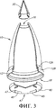
Фиг.3 представляет собой вид в разобранном состоянии с местным разрезом дозирующего узла, показанного на фиг.1.Figure 3 is a disassembled view with a local section of the dosing unit shown in figure 1.
Фиг.4 представляет собой вид в разобранном состоянии с местным разрезом кассеты, показанной на фиг.1.Figure 4 is an exploded view with a local section of the cartridge shown in figure 1.
Фиг.5 представляет собой детализированный вид с местным разрезом двухсекционной контейнерной системы, показанной на фиг.1, с подвижным элементом в закупоренном положении;FIG. 5 is a detail cutaway view of the two-section container system shown in FIG. 1 with the movable member in the clogged position; FIG.
Фиг.6 представляет собой детализированный вид с местным разрезом двухсекционной контейнерной системы, показанной на фиг.1, с подвижным элементом в раскупоренном положении.Fig.6 is a detailed view with a local section of the two-section container system shown in Fig.1, with the movable element in the uncorked position.
Фиг.6А представляет собой вид в перспективе другого варианта осуществления двухсекционной контейнерной системы, показанной на фиг.1.FIG. 6A is a perspective view of another embodiment of the two-section container system shown in FIG.
Фиг.7 представляет собой детализированный вид с местным разрезом другого варианта осуществления соединительного устройства для закупоривающего элемента дозирующего узла и верхней закупоривающей перегородки кассеты.Fig.7 is a detailed view with a local section of another variant implementation of the connecting device for the clogging element of the metering unit and the upper clogging partition of the cartridge.
Фиг.8 представляет собой вид в перспективе дозирующего узла и кассеты в другом варианте осуществления соединительного устройства для закупоривающего элемента дозирующего узла и верхней закупоривающей перегородки кассеты кассеты.Fig. 8 is a perspective view of a dispensing assembly and a cartridge in another embodiment of a connecting device for a clogging member of a dispensing assembly and an upper clogging partition of a cartridge cassette.
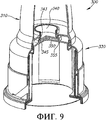
Фиг.9 представляет собой вид с местным разрезом двухсекционного контейнера, собранного из блоков, показанных на фиг.8, с подвижным элементом, находящимся в закупоренном положении.Fig.9 is a view with a local section of a two-section container assembled from the blocks shown in Fig.8, with a movable element in the clogged position.
Фиг.10 представляет собой вид с местным разрезом двухсекционного контейнера, собранного из блоков, показанных на Фиг.8, с подвижным элементом, находящимся в раскупоренном положении.Figure 10 is a view with a local section of a two-section container assembled from the blocks shown in Fig. 8, with a movable element in an uncorked position.
Чертежи являются только схематическими и не требуют указания масштаба.The drawings are only schematic and do not require an indication of scale.
Подробное описание изобретенияDETAILED DESCRIPTION OF THE INVENTION
Приводятся отдельные примеры многосекционных контейнеров для иллюстрации различных характерных конструкций и примеров осуществления данного изобретения. Изобретение не должно считаться ограниченным этими вариантами осуществления. Эти контейнеры также могут быть использованы для различных целей, например, двух- или более секционные контейнеры для медицинских препаратов, пищевых порошков, восстанавливаемых жидкостью, алкогольных напитков для образования коктейлей с другими ингредиентами или различных безалкогольных напитков, которые приготавливаются из порошков, где один отсек содержит один компонент, а другой отсек содержит другой компонент, которые смешиваются с образованием определенного состава. Эти многосекционные контейнеры могут также быть использованы для хранения некоторого количества вещества, которое должно быть дозировано в заданных необходимых количествах. Например, в варианте осуществления двухсекционного контейнера одна секция может вмещать некоторый запас лекарственного средства, а второй отсек может иметь конструкцию и размеры для заданного разового дозирования данного лекарственного средства. Для дозирования средства укупоривания, разделяющие эти два отсека, раскупориваются, образуя проход, соединяющий эти отсеки и позволяющий лекарственному средству заполнить второй отсек. После заполнения второго отсека они могут быть разделены снова путем закупоривания средств укупоривания и отмеренное содержимое второго отсека может быть выдано.Separate examples of multi-section containers are provided to illustrate various representative designs and embodiments of the present invention. The invention should not be considered limited by these embodiments. These containers can also be used for various purposes, for example, two or more sectional containers for medical products, liquid reconstituted food powders, alcoholic beverages for the formation of cocktails with other ingredients, or various soft drinks that are prepared from powders, where one compartment contains one component and the other compartment contains another component that mix to form a specific composition. These multi-section containers can also be used to store a certain amount of substance, which must be dosed in predetermined required quantities. For example, in an embodiment of a two-section container, one section can hold a certain supply of a drug, and the second compartment can have a design and dimensions for a given single dose of a given drug. For dispensing, the closures separating these two compartments are uncorked, forming a passage connecting these compartments and allowing the drug to fill the second compartment. After filling in the second compartment, they can be separated again by clogging the closures and the measured contents of the second compartment can be dispensed.
На фиг.1 показан предпочтительный вариант осуществления двухсекционной контейнерной системы 100. Этот двухсекционный контейнер 100 собран из двух блоков: дозирующего узла 10 и кассеты 30. Каждый из этих блоков представляет собой индивидуально закупориваемый контейнер, который может быть заполнен компонентом, закупорен и может обеспечивать его хранение.1 shows a preferred embodiment of a two-
На фиг.2 показаны дозирующий узел 10 и кассета 30, отсоединенные друг от друга как отдельные блоки. Оба эти блока 10, 30 могут представлять собой контейнеры, имеющие закупориваемые отверстия на верхних и нижних торцах. Буртик 12, предусмотренный на нижнем краю дозирующего узла 10, входит в контакт с ободком 32, предусмотренным на верхнем краю кассеты 30 тогда, когда дозирующий узел 10 и кассету 30 собирают в двухсекционный контейнер 100. Диаметры буртика 12 и ободка 32 таковы, что они предпочтительно входят в контакт с образованием уплотнения. Это уплотнение должно быть достаточно плотным для предполагаемого использования контейнера 100. В предпочтительном варианте осуществления изобретения уплотнение должно быть таким, чтобы предохранять содержимое контейнера от утечки, а нежелательные вещества - от попадания в собранный контейнер и возможного загрязнения или нарушения качества содержимого контейнера 100.Figure 2 shows the
В показанном примере буртик 12 имеет больший диаметр, чем ободок 32, и плотно прилегает к наружной поверхности ободка 32. Однако дозирующий узел 10 и кассета 30 могут иметь и другие разнообразные конструкции для плотного соединения друг с другом с образованием уплотнения. Сопряженные поверхности буртика 12 и ободка 32 могут иметь рельефные уплотняющие выступы, которые образуют фрикционное уплотнение по сопряженным поверхностям. В качестве альтернативы по меньшей мере одна из сопряженных поверхностей может иметь уплотнительные элементы из эластомера для образования компрессионного уплотнения сопряженных поверхностей.In the shown example, the
Нижний торец дозирующего узла 10 закупорен при помощи закупоривающего элемента 40, а верхний торец кассеты 30 закупорен при помощи верхней закупоривающей перегородки 50. По одному из вариантов осуществления данного изобретения этот закупоривающий элемент 40 и верхняя закупоривающая перегородка 50 выполнены с возможностью соединения друг с другом, когда верхняя закупоривающая перегородка 50 перемещается вдоль оси вниз. Таким образом, если верхнее отверстие кассеты 30 раскупорено, то закупоривающий элемент 40 также оттянут вниз вместе с верхней закупоривающей перегородкой 50, раскупоривая при этом нижнее тоцевое отверстие дозирующего узла 10. Конкретные способы, при помощи которых соединение этих двух закупоривающих устройств (закупоривающего элемента 40 и верхней закупоривающей перегородки 50) может осуществляться различными путями без выхода за пределы объема настоящего изобретения.The lower end of the
Например, в варианте исполнения, показанном на фиг.2, закупоривающий элемент 40 имеет два или более соединительных выступа 45 на нижней поверхности, то есть поверхности, обращенной к кассете 30, когда дозирующий узел 10 и кассета 30 собраны вместе. Верхняя закупоривающая перегородка 50 кассеты 30 имеет собственную группу из двух или более соединительных выступов 55, которые соответствуют соединительным выступам 45. Соединительные выступы 45, 55 расположены по окружности с промежутками 45А, 55А между соединительными выступами 45 и 55 соответственно. Когда дозирующий узел 10 и кассету 30 сводят вместе и собирают, соединительные выступы 45, 55 совмещаются с промежутками 55А, 45А соответственно таким образом, что соединительные выступы 45, 55 не мешают друг другу.For example, in the embodiment shown in FIG. 2, the
На фиг.3 показан вид с местным разрезом дозирующего узла 10, где соединительные выступы 45 видны более подробно. Соединительные выступы 45 имеют J-образный профиль и выступают из закупоривающего элемента 40 так, что верхняя часть J-образных соединительных выступов 45 прикреплена к закупоривающему элементу 40, причем нижняя часть J-образных соединительных выступов 45 образует запирающие ребра 47. Дозирующий узел 10 имеет два отверстия: верхнее отверстие 16 и нижнее отверстие 18. Верхнее отверстие 16 может быть закупорено при помощи верхнего закупоривающего элемента 20. Нижнее отверстие 18 определяется буртиком 12. Буртик 12 может содержать верхнюю часть 12А буртика и нижнюю часть 12В буртика. Нижний закупоривающий элемент 40 входит в контакт с верхней частью 12А буртика для закупоривания нижнего отверстия 18 дозирующего узла 10. Предпочтительно нижний закупоривающий элемент 40 и верхняя часть 12А буртика выполнены так, чтобы входить в контакт и образовывать уплотнение. Нижний закупоривающий элемент 40 может быть фрикционной пробкой, пробкой-защелкой или выполнен с использованием других способов и устройств закупоривания, которые обеспечивают уплотнение необходимого качества. Разумеется, качество уплотнения, образованного нижним закупоривающим элементом 40 или любым другим средством укупоривания в контейнерном устройстве, будет зависеть от конкретного назначения, однако в одном из предпочтительных вариантов осуществления настоящего изобретения эти уплотнения должны как минимум предохранять содержимое блоков от утечки, а нежелательные вещества - от попадания в блоки и возможного загрязнения или нарушения качества содержимого контейнера.Figure 3 shows a view with a local section of the
Уплотнение, образованное в верхнем отверстии 16 верхним закупоривающим элементом 20, предпочтительно таково, что дозирующий узел может быть заполнен или жидкостями, или твердыми веществами, и также защищает содержимое дозирующего узла от загрязнения в процессе хранения. Верхний закупоривающий элемент 20 может быть навинчивающейся крышкой, фрикционной пробкой, пробкой-защелкой, перегородкой из термоусадочной пленки или выполнен с использованием других способов или устройств для закупоривания.The seal formed in the
На фиг.4 показан вид в разобранном состоянии с местным разрезом кассеты 30, которая может быть введена в контакт с дозирующим узлом 10 для образования двухсекционного контейнера. Многосекционное контейнерное устройство и контейнерная система, в которой используется кассета, такая как кассета 30, подробно описаны в находящейся на рассмотрении заявке США №10/214, 374, поданной б августа 2002 г., сущность которой включена в это описание посредством ссылки.Figure 4 shows an exploded view with a local section of the
Кассета 30 содержит корпус 31 кассеты с верхним отверстием 36, ограниченным ободком 32, и подвижный элемент 56, предусмотренный в корпусе 31 кассеты. Подвижный элемент 56 выполнен с возможностью осевого перемещения в корпусе 31 кассеты между закупоренным положением и раскупоренным положениям. В закупоренном положении верхняя закупоривающая перегородка 50 подвижного элемента вступает в контакт с ободком 32 и закупоривает верхнее отверстие 36. В раскупоренном положении подвижный элемент 56 смещен вдоль оси от ободка 32, оставляя верхнеее отверстие 36 открытым. Нижнее отверстие 38 кассеты 30 ограничено нижним краем подвижного элемента 56, что обеспечивает доступ к внутреннему пространству кассеты 30 таким образом, что кассета 30 может быть заполнена содержимым. Нижнее отверстие 38 может быть закупорено каким-либо подходящим закрывающим элементом 60. Закрывающий элемент 60 может быть навинчивающейся крышкой, фрикционной пробкой, пробкой-защелкой, перегородкой из термоусадочной пленки или выполнен с использованием других способов или устройств для закупоривания.The
Когда кассета 30 и дозирующий узел 10 собраны, ободок 32 вставлен часть 12 с буртиком дозирующего узла 10. Ободок 32 и часть 12 с буртиком выполнены с возможностью образования уплотнения соответствующего качества для данного назначения. Сопряженные поверхности ободка 32 и части 12 с буртиком могут иметь уплотнительные выступы или другие им подобные конструктивные элементы, которые обеспечивают фрикционное уплотнение сопряженных поверхностей. Например, сопряженные поверхности могут быть выполнены из эластомерного материала для образования уплотнения. В качестве альтернативы ободок 32 и часть 12 с буртиком могут иметь резьбу, так что дозирующий узел 10 и кассета 30 для сборки могут быть свинчены вместе.When the
Подвижный элемент 56 имеет управляемую потребителем часть 52 для перемещения подвижного элемента 56 вдоль оси между закупоренным положением и раскупоренным положением. Для управления осевым перемещением подвижного элемента 56 подвижный элемент 56 может иметь один или более направляющих выступов 54, а корпус 31 кассеты имеет соответствующее количество направляющих канавок 34, в которых размещены направляющие выступы. Количество направляющих канавок 34 и направляющих выступов 54 не обязательно должно быть одинаковым. Например, может быть предусмотрено больше направляющих канавок 34, чем направляющих выступов 54. Как показано на фиг.1-4, направляющие канавки 34 имеют S-образную форму с концами, образующими горизонтальные участки. При повороте управляемой части 52 вокруг продольной оси кассеты 30 в направлении, указанном стрелкой А на управляемой части 52, изображенной на фиг.1 и 2, направляющие выступы 54 будут отслеживать дорожку направляющих канавок 34 и подвижный элемент 56 будет соответственно перемещаться. Таким образом, подвижный элемент 56 сначала будет только вращаться относительно своей продольной оси без всякого осевого движения, а затем подвижный элемент 56 будет перемещаться по меньшей мере в осевом направлении (то есть вдоль продольной оси кассеты 30).The
В процессе начальной фазы перемещения подвижного элемента 56 без всякого осевого движения соединительные выступы 45, 55 переводятся во взаимозамкнутое положение. Затем в процессе осевого перемещения подвижного элемента 56 верхняя закупоривающая перегородка 50, и сцепленный с ней закупоривающий элемент 40 одновременно вскрываются. Подвижный элемент 56 прикреплен к закупоривающей перегородке 50 посредством одного или более присоединительных элементов 58. Поскольку между присоединительными элементами 58 имеются промежутки 59, то они позволяют соединить внутреннее пространство кассеты 30 (определяемое подвижным элементом 56) с внешней средой через верхнее отверстие 36, когда подвижный элемент 56 находится в раскупоренном положении.During the initial phase of movement of the
На фиг.4 соединительные выступы 55, выполненные на верхней закупоривающей перегородке 50 подвижного элемента 56, показаны более подробно. Подобно соединительным выступам 45, соединительные выступы 55 также имеют J-образный профиль и выступают над верхней поверхностью верхней закупоривающей перегородки 50. Верхняя часть J-образных соединительных выступов 55 присоединена к закупоривающей перегородке 50 посредством нижней части J-образных соединительных выступов 55, образуя запирающие ребра 57. После того как дозирующий узел 10 и кассета 30 собраны вместе, как показано на фиг.1, как только подвижный элемент 56 поворачивается в резельтате поворота управляемой части 52 в направлении стрелки А, соединительные выступы 45 и 55 совмещаются друг с другом таким образом, что запирающие ребра 47 и 57 сцепляются. Как видно из фиг.3 и 4, соединительные выступы 45 ориентированы своими запирающими ребрами 47 радиально наружу, тогда как соединительные выступы 55 ориентированы своими запирающими ребрами 57 радиально внутрь таким образом, что они заходят друг за друга и сцепляются друг с другом. Разумеется, ориентация обоих запирающих ребер 47, 57 может быть и обратной.4, the connecting
На фиг.5 показан детализированный вид с местным разрезом двухсекционного контейнера 100 в сборе с блоками в закупоренном состоянии. Нижняя часть 12В буртика дозирующего узла 10 и ободок 32 кассеты 30 входят в плотный контакт. Нижний закупоривающий элемент 40 входит в плотный контакт с верхней частью 12А буртика дозирующего узла 10, закупоривая нижнее отверстие дозирующего узла 10. Подвижный элемент 56 находится в своем закупоренном положении так, что верхняя закупоривающая перегородка 50 входит в плотный контакт с верхним отверстием кассеты 30, а соединительные выступы 45 и 55 находятся в расцепленном положении. Нижнее отверстие кассеты 30 закупорено закрывающим элементом 60.Figure 5 shows a detailed view with a local section of a two-
На фиг.6 показан вид с местным разрезом двухсекционного контейнера 100 в сборе с блоками в раскупоренном состоянии таким образом, что две секции сообщены друг с другом. Подвижный элемент 56 перемещен вдоль оси в раскупоренное положение, и значит, направляющий выступ 54 находится в своем самом нижнем положении в направляющей канавке 34. Нижний закупоривающий элемент 40 остается соединенным с верхней закупоривающей перегородкой 50 кассеты 30 посредством сцепленных между собой соединительных выступов 45 и 55. Нижний закупоривающий элемент 40 оттянут вниз в результате перемещения вдоль оси подвижного элемента 56 и выведен из контакта с верхней частью 12А буртика.Figure 6 shows a view with a local section of a two-
Когда двухсекционный контейнер 100 правильно собран и соединительные выступы 45 и 55 сцеплены между собой, а потребитель поворачивает управляемую часть 52 кассеты 30 и перемещает подвижный элемент 56 в раскупоренное положение, и верхняя закупоривающая перегородка 50 кассеты 30, и нижний закупоривающий элемент 40 дозирующего узла 10 будут раскупорены и внутренние пространства дозирующего узла 10 и кассеты 30 будут находиться в гидравлической связи. Разумеется, прочность соединения, выполненного путем зацепления соединительных выступов 45 и 55, должна быть достаточно крепкой для того, чтобы оттянуть и раскупорить нижний закупоривающий элемент 40.When the two-
Взаимное сцепление верхней закупоривающей перегородки 50 и нижнего закупоривающего элемента 40 блоков 30 и 10 соответственно позволяет потребителю хранить каждый компонент состава в закупоренных блоках и собирать их в контейнер, тем не менее сохраняя блоки в закупоренном состоянии для приготовления состава. Поскольку блоки могут оставаться в закупоренном состоянии при сборке их в контейнер, риск загрязнения сохраняемого содержимого составных элементов сводится к минимуму.The mutual engagement of the
В другом варианте осуществления контейнерной системы 100, когда блоки 10 и 30 сведены вместе, дозирующий узел 10 и кассета 30 могут быть повернуты или вращаться относительно их продольной оси в противоположных направлениях таким образом, что соединительные выступы 45 и 55 совмещаются друг с другом и зацепляются своими запирающими ребрами 47 и 57.In another embodiment of the
В другом варианте осуществления контейнерной системы 100 каждый из закупоривающих устройств (закупоривающий элемент 40 и верхняя закупоривающая перегородка 50) могут иметь единственный соединительный выступ на каждом из этих закупоривающих устройств. Например, каждый из этих закупоривающих устройств может иметь соединительный выступ, который простирается полукругом.In another embodiment of the
На фиг.6А показан другой вариант осуществления контейнерной системы 100А. В этом варианте осуществления подвижный элемент 56А может быть выполнен с возможностью предотвращения возврата этого элемента в запечатанное положение после того, как он перемещен вдоль оси в свое раскупоренное положение. Например, дополнительно к направляющим выступам 54А подвижный элемент 56А может иметь вторую группу выступов 51А, расположенных ближе к нижнему краю подвижного элемента 56А так, что когда подвижный элемент 56А смещен вдоль оси в свое раскупоренное положение, выступы 51А выступают наружу под корпусом 31А кассеты. Выступы 51А имеют достаточную высоту для того, чтобы входить в контакт с корпусом 31А кассеты с целью предупреждения возврата подвижного элемента 56А в свое закупоренное положение. В этом варианте осуществления корпус 31А кассеты и подвижный элемент 56А изготовлены из достаточно упругих материалов, для размещения подвижного элемента 56А, с выступами 51А, выступающими наружу из его внешней поверхности, в корпусе 31А кассеты. Когда кассета 30А в этом варианте осуществления предварительно собрана, выступы 51А предохраняют подвижный элемент 56А от возврата в его первоначальное закупоренное положение. Такая особенность предотвращает нежелательное повторное использование контейнера после того, как его содержимое исчерпано.6A shows another embodiment of a
Для специалиста среднего уровня в данной области техники очевидно, что закрывающий элемент 60, который закупоривает нижнее отверстие 38 кассеты 30, может быть выполнен с возможностью принимать форму, подобную нижнему закупоривающему элементу 40 дозирующего узла 10. Например, закрывающий элемент 60 может также быть выполнен с конструктивными элементами, подобными соединительным выступам 45 таким образом, что вторая кассета (не показана) может быть присоединена к нижнему торцу кассеты 30, добавляя третий отсек к контейнерной системе 100.It will be apparent to one of ordinary skill in the art that the
Подобным образом любое количество кассет может быть присоединено последовательно таким способом для образования многосекционного контейнерной системы, имеющей любое требуемое количество секций. Кроме того, многосекционная контейнерная система может быть скомпонована путем присоединения двух или более кассет последовательно без дозирующего узла. После того как содержимое кассет смешано, будь то жидкости, порошки или их комбинации, содержимое может быть непосредственно подано через крайнее отверстие одной из двух крайних кассет. Другими словами, смешанное содержимое может быть подано через верхнее отверстие верхней кассеты или нижнее отверстие нижней кассеты. Если отдельное дозирующее устройство обусловливается конкретным назначением, соответствующее дозирующее устройство может быть присоединено к отверстию дозирующего узла.Similarly, any number of cassettes can be connected in series in this manner to form a multi-section container system having any desired number of sections. In addition, a multi-section container system can be arranged by attaching two or more cassettes in series without a metering unit. After the contents of the cassettes are mixed, be it liquids, powders, or combinations thereof, the contents can be directly fed through the extreme opening of one of the two extreme cassettes. In other words, the mixed contents may be supplied through the upper opening of the upper cassette or the lower opening of the lower cassette. If a separate metering device is determined by a specific purpose, the corresponding metering device can be attached to the opening of the metering unit.
Для специалиста среднего уровня в данной области техники понятно, что другая конфигурация многосекционной контейнерной системы может содержать одну или несколько кассет, как уже описывалось, присоединенных к обоим открытым торцам дозирующего узла. В другом варианте осуществления дозирующий узел может быть контейнером, подобным бутылке, имеющим только одно отверстие. Таким же образом одна или несколько кассет могут быть присоединены последовательно к такому дозирующему узлу для составления многосекционной контейнерной системы.It will be understood by a person skilled in the art that another configuration of a multi-section container system may comprise one or more cassettes, as already described, attached to both open ends of the dispensing assembly. In another embodiment, the dispensing assembly may be a container, similar to a bottle, having only one opening. In the same way, one or more cassettes can be connected in series to such a metering unit to form a multi-section container system.
Кроме того, согласно одному из вариантов осуществления настоящего изобретения две или более кассет могут быть собраны последовательно для составления многосекционного контейнера. Каждая из таких кассет в комплекте представляет собой закупоренный отсек, вмещающий компонент состава, предназначенный для смешивания. После того как содержимое контейнерной системы смешано и готово к дозированию, подвижный элемент самой верхней кассеты в этой системе перемещается в раскупоренное положение таким образом, что смешанный состав может быть подан через верхнее отверстие самой верхней кассеты. При необходимости соответствующее дозирующее устройство, такое как детская соска для кормления, может быть присоединено к верхнему отверстию самой верхней кассеты.In addition, according to one embodiment of the present invention, two or more cassettes can be assembled in series to form a multi-section container. Each of these cassettes in the kit is a clogged compartment containing a component of the composition for mixing. After the contents of the container system are mixed and ready for dispensing, the movable element of the uppermost cassette in this system is moved to the uncorked position so that the mixed composition can be fed through the upper opening of the uppermost cassette. If necessary, an appropriate metering device, such as a baby nipple for feeding, can be attached to the upper opening of the uppermost cassette.
На фиг.7 показана двухсекционная контейнерная система 200 согласно другому варианту осуществления данного изобретения, в котором контейнер собран с дозирующим узлом 210 и кассетой 230. Нижнее отверстие 218 дозирующего узла 210 имеет меньший диаметр, чем в описанных выше вариантах осуществления. Меньший диаметр нижнего отверстия 218 может быть более пригодным для применения, требующего заполнения дозирующего узла 210 компонентом под давлением. Путем уменьшения размера нижнего отверстия закупоривающий элемент 240 соответственно становится меньше, и таким образом вызванное внутренним давлением усилие, действующее на закупоривающий элемент 240, может быть уменьшено. Это сводит к минимуму возможность выталкивания закупоривающего элемента 240 из закупоренного положения перед сборкой с кассетой. Закупоривающий элемент 240 меньшего диаметра имеет множество J-образных соединительных выступов 245 на стороне, обращенной к кассете 230. Подвижный элемент 256 имеет верхнюю закупоривающую перегородку 250, которая входит в плотный контакт с ободком 232, когда подвижный элемент 256 находится в закупоренном положении. Множество J-образных соединительных выступов 255 предусмотрены на верхней поверхности верхней закупоривающей перегородки 250 для соединения с закупоривающим элементом 240 путем сцепления с соединительными выступами 245. В этом варианте осуществления соединительные выступы 245 и 255 выполнены в виде множества выступов, подобных соединительным выступам 45 и 55 в контейнере 100, однако соединительные выступы 245 и 255 выполнены по кругу с минимальными промежутками между соседними соединительными выступами. Фактическое количество выступов, предусмотренных для каждой группы 245 и 255, может изменяться в зависимости от конкретного применения и относится к вопросу выбора конструкции. Эти соединительные выступы 245 сцепляются с соединительными выступами 255 посредством защелки, когда дозирующий узел 210 и кассета 230 сведены вместе для сборки. Соединительные выступы 245 и 255 выполнены по кругу, причем соединительные выступы 245 расположены по кругу меньшего диаметра. Также соединительные выступы 245 и 255 ориентированы таким образом, что загнутые концы J-образного профиля соединительных выступов 245 обращены к загнутым концам J-образного профиля соединительных выступов 255. Когда дозирующий узел 210 и кассета 230 сведены вместе, соединительные выступы 245 и 255 упруго изгибаются, позволяя соединительным выступам 245 проскальзывать внутрь окружности, образованной соединительными выступами 255, до их сцепления. В этом варианте осуществления вращательное движение подвижного элемента 256 не требуется для сцепления соединительных выступов 245 и 255.7 shows a two-
Для специалиста среднего уровня в данной области техники очевидна конструкция соединительных выступов 245 и 255 в других соответствующих конфигурациях. Например, соединительные выступы 245 и 255 могут быть цельными кольцевыми конструктивными элементами.For a person of ordinary skill in the art, the design of the connecting
На фиг.8 показан другой вариант осуществления двухсекционной контейнерной системы 300, в которой соединительное устройство между нижним закупоривающим элементом дозирующего узла и верхней закупоривающей перегородкой кассеты предусмотрены в различной конфигурации. В этом варианте осуществления нижний закупоривающий элемент 340 дозирующего узла 310 имеет выступающую часть 343, которая простирается вниз и имеет нижний торец эллиптической формы, имеющий два выступа 345, которые выходят за пределы выступающей части 343. Верхняя закупоривающая перегородка 350 кассеты 330 имеет два соединительных выступа 355 J-образного профиля. Соединительные выступы 355 расположены на равном расстоянии от центра верхней закупоривающей перегородки 350 с загнутыми концами J-образных соединительных выступов 355, обращенными друг к другу. Верхнее отверстие дозирующего узла 310 закупоривается навинчивающейся крышкой 320.FIG. 8 shows another embodiment of a two-
Фиг.9 представляет собой вид с местным разрезом полностью собранной контейнерной системы 300, где конструкция, описанная выше, может быть видна более подробно. Нижнее отверстие дозирующего узла 310 закупорено закупоривающим элементом 340. На этом виде дозирующий узел 310 и кассета 330 собраны вместе, однако закупоривающий элемент 340 и верхняя закупоривающая перегородка 350 еще не соединены вместе. Как показано, дозирующий узел 310 и кассета 330 ориентированы таким образом, что выступы 345 эллиптического нижнего торца закупоривающего элемента 340 расположены между двумя соединительными выступами 355. Для присоединения закупоривающего элемента 340 к верхней закупоривающей перегородке 350 потребитель должен повернуть дозирующий узел 310 и кассету 330 в противоположных направлениях вокруг продольной оси системы, тем самым вызывая поворот выступов 345 эллиптического нижнего торца закупоривающего элемента 340 для проскальзывания под загнутый край J-образных соединительных выступов 355.Fig.9 is a view with a local section of a fully assembled
На фиг.10 показана двухсекционная контейнерная система 300 после перемещения вдоль оси подвижного элемента 356 в свое раскупоренное положение с раскупориванием соединенных закупоривающего элемента 340 и верхней закупоривающей перегородки 350. Верхняя секция 313 (определяемая внутренним пространством дозирующего узла 310) и нижняя секция 333 (определяемая внутренним пространством подвижного элемента 356) контейнерной системы 300 при этом оказываются в гидравлической связи через нижнее отверстие 318 дозирующего узла 310 и являются выведенными из закупоренного положения, оставляя нижнее отверстие 318 дозирующего узла 310 открытым. Нижнее отверстие кассеты 330 показано закупоренным закрывающим элементом 360. Как уже указывалось ранее в связи с контейнерной системой 100, в другом варианте осуществления данного изобретения нижний торец подвижного элемента 356 кассеты 330 может быть выполнен с образованием конструкции, подобной конструкции нижнего торца дозирующего узла 310. Таким образом, вторая кассета может быть присоединена к нижнему торцу кассеты 330 для образования третьей секции контейнерной системы 300.Figure 10 shows a two-
Разумеется, что приведенные выше описания служат только примерами и что возможны многие другие варианты осуществления, не выходящие за пределы сущности и объема настоящего изобретения. Блоки, кассеты и дозирующие узлы, описанные выше и показанные на фигурах, являются только примерами. Блоки, представляющие собой другие варианты конструкции, описанные здесь, не выходят за пределы настоящего изобретения. Например, многосекционное контейнерное устройство по настоящему изобретению может быть выполнено таким образом, что дозирующий узел выполнен с возможностью размещения заданного количества вещества. Такой контейнер может быть использован для хранения некоторого объема насыпного (наливаемого) вещества в разных секциях и использования дозирующего узла для отмеривания заданной разовой дозы вещества для дозирования. Нижний закупоривающий элемент дозирующего узла может быть открыт посредством перемещения вдоль оси подвижного элемента кассеты, который присоединен к дозирующему узлу и позволяет содержимому кассеты наполнять дозирующий узел. Затем закупоривающий элемент дозирующего узла вновь закупоривается посредством перемещения вдоль оси этого подвижного элемента в свое закупоренное положение. Теперь дозирующий узел заполнен заданным количеством вещества, которое может быть подано через отдельное дозирующее отверстие на верхнем конце дозирующего узла.Of course, that the above descriptions are only examples and that many other embodiments are possible without departing from the spirit and scope of the present invention. The blocks, cassettes, and metering units described above and shown in the figures are only examples. Blocks representing other design options described herein are not outside the scope of the present invention. For example, the multi-section container device of the present invention may be configured such that the metering unit is configured to accommodate a predetermined amount of a substance. Such a container can be used to store a certain volume of bulk (poured) substance in different sections and to use a dosing unit to measure a given single dose of a substance for dosing. The lower clogging element of the metering unit can be opened by moving along the axis of the movable element of the cartridge, which is attached to the metering unit and allows the contents of the cartridge to fill the metering unit. Then, the clogging element of the metering unit is again clogged by moving along the axis of this movable element to its clogged position. Now the metering unit is filled with a predetermined amount of substance that can be supplied through a separate metering hole at the upper end of the metering unit.
Claims (6)
Applications Claiming Priority (2)
| Application Number | Priority Date | Filing Date | Title |
|---|---|---|---|
| US10/294,020 | 2002-11-12 | ||
| US10/294,020 US6959807B2 (en) | 2002-11-12 | 2002-11-12 | Multi-compartment container assembly system |
Publications (2)
| Publication Number | Publication Date |
|---|---|
| RU2005115442A RU2005115442A (en) | 2006-01-20 |
| RU2329926C2 true RU2329926C2 (en) | 2008-07-27 |
Family
ID=32229766
Family Applications (1)
| Application Number | Title | Priority Date | Filing Date |
|---|---|---|---|
| RU2005115442/12A RU2329926C2 (en) | 2002-11-12 | 2003-11-12 | Multi-sectional container system |
Country Status (11)
| Country | Link |
|---|---|
| US (1) | US6959807B2 (en) |
| EP (1) | EP1569854B1 (en) |
| JP (1) | JP4236111B2 (en) |
| KR (1) | KR101069449B1 (en) |
| CN (1) | CN100363238C (en) |
| AT (1) | ATE400508T1 (en) |
| AU (1) | AU2003279505A1 (en) |
| DE (1) | DE60322098D1 (en) |
| ES (1) | ES2310674T3 (en) |
| RU (1) | RU2329926C2 (en) |
| WO (1) | WO2004043789A2 (en) |
Families Citing this family (25)
| Publication number | Priority date | Publication date | Assignee | Title |
|---|---|---|---|---|
| IL160784A (en) * | 2004-03-08 | 2011-02-28 | Mlis Projects Ltd | Cartridge unit for a multi-compartment container assembly |
| US7534756B2 (en) * | 2005-02-25 | 2009-05-19 | Solutions Biomed, Llc | Devices, systems, and methods for dispensing disinfectant solutions comprising a peroxygen and transition metal |
| US7473675B2 (en) * | 2005-02-25 | 2009-01-06 | Solutions Biomed, Llc | Disinfectant systems and methods comprising a peracid, alcohol, and transition metal |
| AU2006218874B2 (en) | 2005-02-25 | 2012-04-12 | Solutions Biomed, Llc | Aqueous disinfectants and sterilants |
| US7507701B2 (en) * | 2005-02-25 | 2009-03-24 | Solutions Biomed, Llc | Aqueous disinfectants and sterilants including transition metals |
| US7475564B2 (en) * | 2005-10-03 | 2009-01-13 | Kagen Kristin W | Container with sealed coolant compartment |
| IL177549A0 (en) * | 2006-08-17 | 2006-12-10 | Mlis Projects Ltd | Container and divider therefor |
| US20090232860A1 (en) * | 2007-08-30 | 2009-09-17 | Larson Brian G | Colloidal metal-containing skin sanitizer |
| US8146758B1 (en) * | 2008-03-07 | 2012-04-03 | Travis Peres | Compartmentalized baby bottle and associated method |
| US9016488B1 (en) * | 2008-03-07 | 2015-04-28 | Travis Peres | Compartmentalized mixing bottle and associated use therefore |
| US8464910B2 (en) | 2008-03-14 | 2013-06-18 | Solutions Biomed, Llc | Multi-chamber container system for storing and mixing fluids |
| US8834014B2 (en) * | 2008-03-24 | 2014-09-16 | Sashco, Inc. | System for providing custom colored sealing compound |
| US8800816B2 (en) * | 2009-03-24 | 2014-08-12 | Sashco, Inc. | System and method of providing individual quantities of custom colored sealing compound |
| WO2010056881A1 (en) | 2008-11-12 | 2010-05-20 | Solutions Biomed, Llc | Multi-chamber container system for storing and mixing liquids |
| US20100120913A1 (en) * | 2008-11-12 | 2010-05-13 | Larson Brian G | Resin catalyzed and stabilized peracid compositions and associated methods |
| WO2010056871A2 (en) | 2008-11-12 | 2010-05-20 | Solutions Biomed, Llc | Two-part disinfectant system and related methods |
| EP2497721B1 (en) * | 2011-03-11 | 2013-11-20 | Sulzer Mixpac AG | Cartridge comprising several components |
| EP2967260A1 (en) * | 2013-03-15 | 2016-01-20 | Christoph Zickler | Beverage container cask |
| US11242236B2 (en) | 2015-03-19 | 2022-02-08 | Phillip LaBarbera | Perfect pour drink mixer |
| BE1023806B1 (en) * | 2016-06-28 | 2017-07-27 | R&O Lab Sprl | MIXING CONTAINER ADAPTABLE TO ANY RECEPTOR CONTAINER |
| GB2559594B (en) * | 2017-02-10 | 2020-07-15 | Dexos Drinks Ltd | A liquid dispenser and method |
| US20200138794A1 (en) | 2017-08-15 | 2020-05-07 | Thomas Julius Borody | Novel parasite therapy |
| MX2020012764A (en) * | 2018-06-01 | 2021-05-27 | In Spirit Group Inc | Multi-compartment beverage bottle system and method. |
| US11478013B2 (en) * | 2020-05-29 | 2022-10-25 | Kyle Thomas Miller | Beverage container rimmer |
| CN115158889B (en) * | 2022-09-05 | 2022-11-29 | 常州远望流体科技有限公司 | Packaging bottle |
Family Cites Families (14)
| Publication number | Priority date | Publication date | Assignee | Title |
|---|---|---|---|---|
| DE3722371A1 (en) * | 1987-07-07 | 1989-01-19 | Henkel Kgaa | TWO-CHAMBER CONTAINER |
| US5000314A (en) * | 1989-01-23 | 1991-03-19 | Bristol-Myers Company | Unit dose package |
| JPH05103819A (en) * | 1991-08-08 | 1993-04-27 | Nissho Corp | Medicine receiving container |
| FR2680357B1 (en) * | 1991-08-16 | 1995-01-06 | Oreal | PACKAGING WITH TWO BOTTLES FOR SEPARATELY STORING ONE OF THE OTHER TWO PRODUCTS, PARTICULARLY LIQUID, AND MIXING THEM AT THE TIME OF THEIR USE. |
| FR2694920B1 (en) * | 1992-08-20 | 1994-10-28 | Oreal | Device for keeping at least two products separated from each other and for mixing them at a desired time. |
| FR2722765B1 (en) * | 1994-07-25 | 1996-08-23 | Oreal | CONTAINER ALLOWING THE STORAGE OF AT LEAST TWO PRODUCTS, THE MIXTURE OF THESE PRODUCTS AND THE DISTRIBUTION OF THE MIXTURE THUS OBTAINED |
| US5638968A (en) * | 1996-02-26 | 1997-06-17 | Baron; Moises S. | Baby bottle extension assembly having storage chamber and release mechanism |
| FR2751942B1 (en) * | 1996-08-02 | 1998-09-11 | Oreal | DEVICE FOR THE SEPARATE STORAGE OF TWO COMPONENTS THEIR MIXTURE AND THE DISTIBUTION OF THE MIXTURE |
| FR2751941B1 (en) * | 1996-08-02 | 1998-09-11 | Oreal | DEVICE FOR THE SEPARATE PACKAGING OF TWO COMPONENTS, THEIR MIXING AND THE DISTRIBUTION OF THE MIXTURE THUS OBTAINED |
| DE19635833C2 (en) * | 1996-09-04 | 1998-08-06 | Henkel Kgaa | Two-component container |
| ES2163268T3 (en) * | 1997-05-15 | 2002-01-16 | R & D Injector Ag | CONTAINER SYSTEM WITH TWO COMPONENTS. |
| FR2764868B1 (en) * | 1997-06-20 | 1999-07-30 | Oreal | DEVICE FOR PACKAGING A MULTI-COMPONENT PRODUCT TO BE STORED SEPARATELY AND MIXED JUST BEFORE USING THE PRODUCT |
| FR2806271B1 (en) * | 2000-03-17 | 2002-05-03 | Oreal | DEVICE FOR THE EXTEMPORANEOUS MIXING OF AT LEAST TWO PRODUCTS |
| ATE375302T1 (en) * | 2001-08-06 | 2007-10-15 | Mlis Projects Ltd | MULTIPLE COMPARTMENT CONTAINER ARRANGEMENT SYSTEM |
-
2002
- 2002-11-12 US US10/294,020 patent/US6959807B2/en not_active Expired - Fee Related
-
2003
- 2003-11-12 ES ES03772612T patent/ES2310674T3/en not_active Expired - Lifetime
- 2003-11-12 KR KR1020057008547A patent/KR101069449B1/en not_active IP Right Cessation
- 2003-11-12 EP EP03772612A patent/EP1569854B1/en not_active Expired - Lifetime
- 2003-11-12 JP JP2004551133A patent/JP4236111B2/en not_active Expired - Fee Related
- 2003-11-12 RU RU2005115442/12A patent/RU2329926C2/en not_active IP Right Cessation
- 2003-11-12 DE DE60322098T patent/DE60322098D1/en not_active Expired - Lifetime
- 2003-11-12 CN CNB2003801080554A patent/CN100363238C/en not_active Expired - Fee Related
- 2003-11-12 WO PCT/IL2003/000950 patent/WO2004043789A2/en active IP Right Grant
- 2003-11-12 AU AU2003279505A patent/AU2003279505A1/en not_active Abandoned
- 2003-11-12 AT AT03772612T patent/ATE400508T1/en not_active IP Right Cessation
Also Published As
| Publication number | Publication date |
|---|---|
| WO2004043789A2 (en) | 2004-05-27 |
| AU2003279505A1 (en) | 2004-06-03 |
| ATE400508T1 (en) | 2008-07-15 |
| CN100363238C (en) | 2008-01-23 |
| WO2004043789A3 (en) | 2005-03-03 |
| JP4236111B2 (en) | 2009-03-11 |
| EP1569854A4 (en) | 2007-03-21 |
| EP1569854A2 (en) | 2005-09-07 |
| US20040089563A1 (en) | 2004-05-13 |
| US6959807B2 (en) | 2005-11-01 |
| JP2006519139A (en) | 2006-08-24 |
| KR20050072826A (en) | 2005-07-12 |
| CN1732111A (en) | 2006-02-08 |
| DE60322098D1 (en) | 2008-08-21 |
| RU2005115442A (en) | 2006-01-20 |
| ES2310674T3 (en) | 2009-01-16 |
| KR101069449B1 (en) | 2011-09-30 |
| AU2003279505A8 (en) | 2004-06-03 |
| EP1569854B1 (en) | 2008-07-09 |
Similar Documents
| Publication | Publication Date | Title |
|---|---|---|
| RU2329926C2 (en) | Multi-sectional container system | |
| US8136660B2 (en) | Multi compartment container system | |
| EP1687208B1 (en) | Cap with storage chamber for secondary material and product with the same | |
| US7523822B2 (en) | Multi-compartment container assembly system | |
| KR100593246B1 (en) | Bottle | |
| US7861854B2 (en) | Cartridge unit for a multi-compartment container assembly | |
| JP2000229670A (en) | Measuring/distributing equipment with multiple component storing/mixing function | |
| CA2572799A1 (en) | A syringe assembly | |
| JP3429275B2 (en) | Multi-chamber container | |
| JPH0710172A (en) | Container and method for simultaneous mixing | |
| CN113727917B (en) | Reconfigurable container-closure system | |
| KR100602418B1 (en) | Container | |
| EP3952695B1 (en) | Reconfigurable container-closure system | |
| CN113950452A (en) | Packaging system for at least one product preparation component and corresponding method for processing product preparation components | |
| KR101811247B1 (en) | Container lid for mixing different kind material | |
| KR200286135Y1 (en) | A case cam use separayion charge and mix to powder or solution of different each otater ponenit | |
| RU2712447C2 (en) | Mixing container | |
| KR20240059377A (en) | Cap assembly for beverage container | |
| CN118102943A (en) | Content container | |
| JPH1191831A (en) | Mixing/dispensing container | |
| CN119284351A (en) | Container sealing device, packaging container and application thereof | |
| KR20000062363A (en) | Container having two or more compartments |
Legal Events
| Date | Code | Title | Description |
|---|---|---|---|
| MM4A | The patent is invalid due to non-payment of fees |
Effective date: 20131113 |