RU2329537C1 - Method of fingerprint image filtration - Google Patents
Method of fingerprint image filtration Download PDFInfo
- Publication number
- RU2329537C1 RU2329537C1 RU2006140704/09A RU2006140704A RU2329537C1 RU 2329537 C1 RU2329537 C1 RU 2329537C1 RU 2006140704/09 A RU2006140704/09 A RU 2006140704/09A RU 2006140704 A RU2006140704 A RU 2006140704A RU 2329537 C1 RU2329537 C1 RU 2329537C1
- Authority
- RU
- Russia
- Prior art keywords
- filter
- curvature
- local
- papillary
- image
- Prior art date
Links
Images


Classifications
-
- G—PHYSICS
- G06—COMPUTING; CALCULATING OR COUNTING
- G06V—IMAGE OR VIDEO RECOGNITION OR UNDERSTANDING
- G06V40/00—Recognition of biometric, human-related or animal-related patterns in image or video data
- G06V40/10—Human or animal bodies, e.g. vehicle occupants or pedestrians; Body parts, e.g. hands
- G06V40/12—Fingerprints or palmprints
- G06V40/1347—Preprocessing; Feature extraction
Landscapes
- Engineering & Computer Science (AREA)
- Computer Vision & Pattern Recognition (AREA)
- Human Computer Interaction (AREA)
- Physics & Mathematics (AREA)
- General Physics & Mathematics (AREA)
- Multimedia (AREA)
- Theoretical Computer Science (AREA)
- Image Processing (AREA)
- Collating Specific Patterns (AREA)
- Apparatus For Radiation Diagnosis (AREA)
Abstract
Description
Изобретение относится к области цифровой обработки изображений, а именно к цифровой фильтрации дактилоскопических изображений, и может быть использовано в криминалистике для идентификации отпечатков папиллярных узоров.The invention relates to the field of digital image processing, namely to digital filtering of fingerprint images, and can be used in forensics to identify fingerprints of papillary patterns.
Современная дактилоскопия использует вычислительную технику для обработки и идентификации дактилоскопических изображений, к которым относятся, в первую очередь, отпечатки пальцев и ладоней. Низкое качество отпечатков приводит к появлению ошибок при сравнении изображений. Для уменьшения количества ошибок изображение улучшают (фильтруют) с помощью направленных цифровых фильтров. Известные методы фильтрации дают хороший результат для участков изображения с малой кривизной папиллярных линий, но малоэффективны для участков с повышенной кривизной.Modern fingerprinting uses computer technology to process and identify fingerprint images, which primarily include fingerprints and palms. Poor print quality results in errors when comparing images. To reduce the number of errors, the image is improved (filtered) using directional digital filters. Known filtering methods give good results for areas of the image with a small curvature of the papillary lines, but are ineffective for areas with increased curvature.
Цифровой фильтр представляет собой математическую функцию двух переменных, задающую трехмерную поверхность. Это позволяет говорить о форме фильтра. Фильтр для улучшения дактилоскопического изображения имеет один или несколько параллельных гребней, из которых наибольшее влияние на результат фильтрации оказывает центральный гребень. Такой фильтр обладает селективным воздействием: в результате применения фильтра яркость пикселов изображения, расположенных в зоне межгребневой борозды, в среднем увеличивается, а яркость пикселов, расположенных в зоне папиллярного гребня в среднем уменьшается.A digital filter is a mathematical function of two variables that defines a three-dimensional surface. This allows us to talk about the shape of the filter. The filter for improving the fingerprint image has one or more parallel ridges, of which the central ridge has the greatest influence on the filtering result. Such a filter has a selective effect: as a result of applying the filter, the brightness of image pixels located in the area of the intercostal groove increases on average, and the brightness of pixels located in the area of the papillary ridge decreases on average.
Для практического применения фильтра на основе задающей фильтр функции строят матрицу коэффициентов, так называемую маску, которую затем применяют к окрестности обрабатываемого пиксела, чтобы определить новое значение яркости для данного пиксела.For the practical use of the filter, a coefficient matrix, the so-called mask, is constructed based on the filter-defining function, which is then applied to the vicinity of the processed pixel to determine a new brightness value for a given pixel.
Наилучшее действие фильтра достигается при точном совпадении ориентации гребней фильтра с ориентацией папиллярных линий в зоне действия фильтра. На участке изображения с повышенной кривизной папиллярные линии существенно меняют свое направление на расстоянии, равном протяженности фильтра. В этих условиях добиться совпадения ориентации фильтра с ориентацией линий удается лишь для небольшого участка линии, в то время как остальные участки имеют иную ориентацию, что отрицательно влияет на результат фильтрации.The best filter effect is achieved when the orientation of the filter ridges coincides exactly with the orientation of the papillary lines in the filter area. In an area of an image with increased curvature, papillary lines substantially change their direction at a distance equal to the length of the filter. Under these conditions, it is possible to achieve the coincidence of the filter orientation with the line orientation only for a small section of the line, while the remaining sections have a different orientation, which negatively affects the filtering result.
В результате обработки такого участка фильтром на изображении могут появиться ложные детали, а истинные могут оказаться потеряны. Чтобы уменьшить искажение изображения фильтром, обычно на искривленных участках уменьшают область действия фильтра. Такое ограничение приводит к тому, что сильно искривленные участки практически не фильтруются.As a result of processing such a section with a filter, false details may appear on the image, and true ones may be lost. In order to reduce the distortion of the image by the filter, usually in the curved areas the scope of the filter is reduced. This limitation leads to the fact that strongly curved sections are practically not filtered.
Известен способ улучшения качества дактилоскопического изображения (A.Erol, U.Halici, G.Ongun. "Feature Selective Filtering for Ridge Extraction" (c) 1999 by CRC Press LLC), заключающийся в обработке изображения при помощи фильтра, который адаптируют к локальным параметрам окрестности обрабатываемой области, путем изменения коэффициентов фильтра.A known method for improving the quality of a fingerprint image (A.Erol, U. Halici, G. Ongun. "Feature Selective Filtering for Ridge Extraction" (c) 1999 by CRC Press LLC), which consists in processing the image using a filter that is adapted to local parameters neighborhood of the treated area, by changing the filter coefficients.
Используемый в указанном способе фильтр является усеченной версией фильтра Габора, разработанного для вызова максимального отклика на папиллярных линиях известной ориентации и известного расстояния между ними на изображении дактилоскопического отпечатка. Импульсная характеристика такого фильтра определяется произведением гауссиана и косинусной плоской волны.The filter used in this method is a truncated version of the Gabor filter, designed to cause the maximum response on papillary lines of known orientation and the known distance between them in the image of a fingerprint. The impulse response of such a filter is determined by the product of a Gaussian and a cosine plane wave.
В пространственной области, когда среднеквадратическое отклонение (далее - СКО) достаточно велико, фильтр дает максимальный отклик на папиллярные линии с частотой следования, равной величине волнового вектора, и ориентированные ортогонально направлению волны. Главный пик в середине соответствует обрабатываемому папиллярному гребню, а боковые пики с меньшей амплитудой соответствуют соседним папиллярным линиям.In the spatial domain, when the standard deviation (hereinafter - RMS) is large enough, the filter gives a maximum response to papillary lines with a repetition rate equal to the magnitude of the wave vector and oriented orthogonally to the direction of the wave. The main peak in the middle corresponds to the processed papillary ridge, and the side peaks with lower amplitude correspond to neighboring papillary lines.
Для адаптации указанного фильтра к локальным параметрам изображения используют следующие локальные значения:To adapt the specified filter to local image parameters, the following local values are used:
- межгребневое расстояние;- intercostal distance;
- ориентация гребня.- orientation of the ridge.
Межгребневое расстояние определяет как величину волнового вектора, так и СКО гауссиана. Величина волнового вектора соответствует частоте колебаний вдоль волнового вектора.The distance between the ridges determines both the magnitude of the wave vector and the standard deviation of the Gaussian. The magnitude of the wave vector corresponds to the frequency of oscillations along the wave vector.
Эксперименты показали, что используемые правила построения указанного фильтра работают очень хорошо, когда ориентация и межгребневое расстояние определены верно. Однако ошибки, возникающие при определении ориентации папиллярной линии, искажают изображение и приводят к потере истинных мелких особенностей и выделению ложных.The experiments showed that the used rules for constructing the specified filter work very well when the orientation and spine distance are determined correctly. However, errors that occur in determining the orientation of the papillary line distort the image and lead to the loss of true small features and the allocation of false ones.
Обычно практически невозможно точно определить ориентацию папиллярной линии на участках плохого качества или на участках изображения с большой кривизной.It is usually almost impossible to accurately determine the orientation of the papillary line in areas of poor quality or in areas of the image with a large curvature.
Для решения этой проблемы параметр угла ориентации папиллярной линии дополнен параметром степени достоверности ориентации (далее - ДО). Коэффициент достоверности ориентации используется для настройки СКО гауссиана. Участки с низкой достоверностью ориентации обрабатываются фильтром с меньшим значением СКО по сравнению со значениями, используемыми для участков с большой достоверностью ориентации. То есть участки с низкой ДО подвергаются менее интенсивной фильтрации, чем участки с большой ДО.To solve this problem, the parameter of the orientation angle of the papillary line is supplemented by the parameter of the degree of orientation accuracy (hereinafter - DO). The orientation confidence coefficient is used to set the standard deviation of the Gaussian. Areas with low orientation accuracy are processed by a filter with a lower standard deviation compared to the values used for areas with high orientation accuracy. That is, areas with low DO undergo less intense filtering than areas with large DO.
Приведенный в той же статье анализ результатов экспериментального применения описанного способа показывает, что для участков с большой кривизной папиллярной линии получены низкие значения достоверности. Это влечет за собой снижение степени фильтрации вплоть до полной невозможности "извлечь" папиллярные линии на этих участках.The analysis of the results of the experimental application of the described method presented in the same article shows that low confidence values were obtained for areas with a large curvature of the papillary line. This entails a decrease in the degree of filtration up to the complete impossibility of "extracting" papillary lines in these areas.
Таким образом, задача корректной обработки искривленных участков авторами не решена, а лишь автоматизировано снижение степени фильтрации проблемных мест.Thus, the authors did not solve the problem of correct processing of curved sections, but only automatically reduced the degree of filtration of problem areas.
В качестве прототипа выбран способ улучшения качества изображения отпечатков пальцев (заявка США №2005163394, Scholze, 28.06.2005), согласно которому выполняют последовательную обработку областей изображения при помощи направленного фильтра, адаптированного к локальным параметрам соответствующих областей изображения, которые включают межгребневое расстояние, ориентацию и кривизну папиллярной линии. Для определения локальных параметров изображения его делят на прямоугольные фрагменты, для каждого из которых определяют локальные параметры. В пространственной области для каждой обрабатываемой точки в соответствии с локальными параметрами изображения строят фильтр Габора. При этом адаптацию фильтра к локальной кривизне осуществляют, подвергая коррекции Фурье-образ фильтра, в частности, изменяют направления главных осей, положение и размер ограничивающего эллипса в частотной области, определяющего область пропускания фильтра. В местах, где направление потока папиллярных линий существенно изменяется, область пропускания увеличивают. В результате селективное направленное воздействие фильтра уменьшается. Это приводит к снижению эффективности фильтра по отношению к типичным помехам на изображении папиллярного узора.As a prototype, a method for improving image quality of fingerprints was chosen (US application No. 2005163394, Scholze, June 28, 2005), according to which sequential processing of image areas is performed using a directional filter adapted to local parameters of the corresponding image areas, which include the intercostal distance, orientation and curvature of the papillary line. To determine the local parameters of the image, it is divided into rectangular fragments, for each of which local parameters are determined. In the spatial domain for each processed point, in accordance with local image parameters, a Gabor filter is constructed. In this case, the filter is adapted to local curvature by correcting the Fourier transform of the filter, in particular, the directions of the main axes, the position and size of the bounding ellipse in the frequency domain defining the filter transmission region are changed. In places where the flow direction of papillary lines changes significantly, the transmission area is increased. As a result, the selective directional effect of the filter is reduced. This leads to a decrease in filter efficiency with respect to typical noise in the image of a papillary pattern.
Задачей настоящего изобретения является создание такого способа фильтрации дактилоскопического изображения, который обеспечивал бы эффективную обработку изображения на участках с высокой кривизной папиллярных линий.The present invention is the creation of such a method of filtering a fingerprint image, which would provide effective image processing in areas with a high curvature of papillary lines.
Решение поставленной задачи достигнуто благодаря созданию способа фильтрации дактилоскопического изображения, заключающегося в последовательной обработке областей изображения при помощи направленного фильтра, имеющего по меньшей мере один центральный гребень и адаптированного к локальным параметрам соответствующих областей изображения, включающим межгребневое расстояние, ориентацию и кривизну папиллярной линии, при котором адаптацию фильтра к локальной кривизне осуществляют путем изгиба по меньшей мере одного центрального гребня фильтра в плоскости пространственных координат таким образом, чтобы приблизить его кривизну к локальной кривизне папиллярной линии.The solution to this problem was achieved by creating a method for filtering a fingerprint image, which consists in sequentially processing image areas using a directional filter having at least one central ridge and adapted to local parameters of the corresponding image areas, including the inter-ridge distance, orientation and curvature of the papillary line, in which the filter is adapted to local curvature by bending at least one central heat nya filter in the plane of spatial coordinates so as to approximate its curvature to the local curvature of the papillary line.
Благодаря такой адаптации фильтра появляется возможность осуществлять фильтрацию участков папиллярных линий, имеющих большую кривизну, без снижения эффективности самой фильтрации.Thanks to this adaptation of the filter, it becomes possible to filter sections of papillary lines that have a large curvature, without compromising the efficiency of the filter itself.
Изгиб может осуществляться путем построения указанного фильтра в криволинейной системе координат, имеющей два семейства координатных линий, в которой координатные линии одного семейства прямолинейны и перпендикулярны к касательной к папиллярной линии в обрабатываемой точке, координатные линии другого семейства изогнуты и имеют кривизну, соответствующую локальной кривизне папиллярной линии, а начало координат совпадает с обрабатываемой точкой.Bending can be done by constructing the specified filter in a curved coordinate system having two families of coordinate lines, in which the coordinate lines of one family are straight and perpendicular to the tangent to the papillary line at the point being processed, the coordinate lines of the other family are curved and have a curvature corresponding to the local curvature of the papillary line , and the origin coincides with the point being processed.
Изгиб может также осуществляться путем построения указанного фильтра в полярной системе координат.Bending can also be carried out by constructing the specified filter in the polar coordinate system.
Гребень может принимать форму дуги окружности. При этом кривизна дуги окружности может быть равна локальной кривизне папиллярной линии.The crest may take the form of an arc of a circle. Moreover, the curvature of the circular arc may be equal to the local curvature of the papillary line.
В качестве направленного фильтра может быть использован фильтр Габора.As a directional filter, a Gabor filter can be used.
Далее следует подробное описание изобретения со ссылками на прилагаемые чертежи, на которых:The following is a detailed description of the invention with reference to the accompanying drawings, in which:
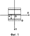
фиг.1 схематически изображает эталонный фильтр;figure 1 schematically depicts a reference filter;
фиг.2 схематически изображает фрагмент узора папиллярных линий;figure 2 schematically depicts a fragment of the pattern of papillary lines;
фиг.3 схематически изображает ориентированный и масштабированный фильтры;figure 3 schematically depicts oriented and scaled filters;
фиг.4 схематически изображает изогнутый фильтр;4 schematically depicts a curved filter;
фиг.5 изображает взаимное расположение используемых систем координат.5 depicts the relative positioning of the used coordinate systems.
Способ фильтрации дактилоскопического изображения заключается в следующем.A method of filtering a fingerprint image is as follows.
На первом этапе обработки строят известным способом (аналитически) эталонный фильтр F(x, у), оптимизированный для фильтрации изображения идеализированного узора, представленного горизонтальными папиллярными линиями с фиксированным межгребневым расстоянием s. Фильтр, определяемый функцией F(x, у), строится в окне D, как показано на фиг.1.At the first stage of processing, a reference filter F (x, y) is constructed in a known manner (analytically), optimized for filtering the image of an idealized pattern represented by horizontal papillary lines with a fixed intercostal distance s. The filter defined by the function F (x, y) is built in window D, as shown in Fig. 1.
Дальнейшие операции выполняют последовательно с каждой точкой обрабатываемого изображения.Further operations are performed sequentially with each point of the processed image.
В системе координат OX′Y′ для обрабатываемой точки О изображения выбирают окрестность, включающую несколько папиллярных гребней, и в данной окрестности определяют локальные параметры изображения. Как показано на фиг.2, для каждой точки, расположенной в центре папиллярного гребня или межгребневой борозды, за направление потока папиллярных линий выбирают направление касательной А к папиллярной линии в этой точке. В остальных точках выбранной окрестности направление определяется интерполяцией значений, полученных для центральных точек. Для уменьшения влияния шума эти направления сглаживаются по упомянутой окрестности точки О. Межгребневое расстояние S для каждой точки упомянутой окрестности точки О определяют перпендикулярно направлению потока в данной точке окрестности. Полученные значения также усредняют по всей упомянутой окрестности. Кривизну С определяют непосредственно в точке О без усреднения.In the coordinate system OX′Y ′, for the processed image point O, a neighborhood including several papillary ridges is selected, and local parameters of the image are determined in this neighborhood. As shown in FIG. 2, for each point located in the center of the papillary ridge or intercostal groove, the direction of the tangent A to the papillary line at this point is selected for the direction of flow of the papillary lines. At the remaining points of the selected neighborhood, the direction is determined by interpolating the values obtained for the central points. To reduce the influence of noise, these directions are smoothed over the said neighborhood of point O. The ridge distance S for each point of the said neighborhood of point O is determined perpendicular to the direction of flow at a given point of the neighborhood. The obtained values are also averaged over the entire mentioned neighborhood. The curvature C is determined directly at point O without averaging.
Далее для обрабатываемой точки изображения строят фильтр, адаптированный к локальным параметрам изображения, полученным для этой точки, включающим направление потока папиллярных линий, межгребневое расстояние и кривизну. Для адаптации фильтра к локальным параметрам изображения выполняют его масштабирование, ориентацию и изгиб.Next, for the processed image point, a filter is constructed that is adapted to the local image parameters obtained for this point, including the direction of the flow of papillary lines, the intercostal distance and curvature. To adapt the filter to the local parameters of the image, its scaling, orientation and bending are performed.
Для выполнения ориентации и масштабирования задают прямоугольную систему координат OX′′Y′′, в которой начало координат совпадает с обрабатываемой точкой О, ось X′′ параллельна направлению потока папиллярных линий в точке О, ось Y′′ перпендикулярна направлению потока (см. фиг.3 и 5). В указанной системе задают квадратное окно D′′, симметричное относительно координатных осей X′′ и Y′′. При этом размеры окна D′′ равны размерам окна D, умноженным на масштабный коэффициент M=S/s, где S - межгребневое расстояние в точке О, a s - фиксированное межгребневое расстояние идеализированного узора. Окно D′′ определяет основание ориентированного и масштабированного фильтра.To perform orientation and scaling, a rectangular coordinate system OX′′Y ′ ′ ′ is defined in which the origin coincides with the processed point O, the X ′ ′ axis is parallel to the flow direction of the papillary lines at the point O, the Y ′ ′ axis is perpendicular to the flow direction (see Fig. .3 and 5). In this system, a square window D ″ is defined that is symmetrical about the coordinate axes X ″ and Y ″. In this case, the size of the window D ′ ′ is equal to the size of the window D multiplied by the scale factor M = S / s, where S is the intercostal distance at point O, and s is the fixed intercostal distance of the idealized pattern. Window D ′ ′ defines the base of the oriented and scaled filter.
В окне D′′ строят ориентированный и масштабированный фильтр, задаваемый функцией F(x′′, у′′). Координаты х′′ и у′′ фильтра в системе координат OX′′Y′′ выражаются через координаты фильтра в системы координат OX'Y' следующим образом:In the window D ′ ′, an oriented and scaled filter is constructed, defined by the function F (x ′ ′, y ′ ′). The coordinates x ′ ′ and y ′ ′ of the filter in the coordinate system OX′′Y ′ ′ ′ are expressed in terms of the coordinates of the filter in the coordinate system OX'Y 'as follows:
х′′=M·x′·cos(α)+M·y′·sin(α);x ′ ′ = M · x ′ · cos (α) + M · y ′ · sin (α);
у′′=M·y′·cos(α)-M·x′·sin(α),y ′ ′ = M · y ′ · cos (α) -M · x ′ · sin (α),
где М - масштабный коэффициент;where M is a scale factor;
α - угол между касательной к папиллярной линии и папиллярной линией в точке О.α is the angle between the tangent to the papillary line and the papillary line at point O.
Далее выполняют переход к криволинейным координатам, имеющим два семейства координатных линий Y′′′ и X′′′, и начало координат в обрабатываемой точке О. Координатные линии Y′′′ одного семейства системы прямолинейны и перпендикулярны локальному направлению папиллярных линий в обрабатываемой точке, а координатные линии X′′′ другого семейства криволинейны, а их кривизна соответствует локальной кривизне С папиллярной линии. В частном случае координатные линии X′′′ могут иметь форму дуги окружности с радиусом кривизны R=1/С.Next, the transition to curvilinear coordinates having two families of coordinate lines Y ″ ″ and X ″ ″ and the origin at the processed point O are made. The coordinate lines Y ″ ″ of one family of the system are straightforward and perpendicular to the local direction of the papillary lines at the processed point, and the coordinate lines X ′ ′ ′ of the other family are curved, and their curvature corresponds to the local curvature C of the papillary line. In a particular case, the coordinate lines X ″ ″ can be in the form of an arc of a circle with a radius of curvature R = 1 / C.
В указанной системе координат строят окно D′′′ (см. фиг.4), которое является криволинейным образом окна D′′. Высота окна D′′′, измеренная вдоль оси Y′′′, равна высоте окна D′′, а ширина окна D′′′, измеренная перпендикулярно оси Y′′′, равна ширине окна D′′.In the indicated coordinate system, a window D ″ ″ is constructed (see FIG. 4), which is a curved image of the window D ″. The height of the window D ″ ″, measured along the axis Y ″ ″, is equal to the height of the window D ″, and the width of the window D ″ ″, measured perpendicular to the axis Y ″ ″, is equal to the width of the window D ″.
В окне D′′′ строят фильтр как функцию криволинейных координат F(x′′′, у′′′). При этом координаты х′′′, у′′′ выражаются через координаты х′′, у′′ с учетом радиуса кривизны R следующим образом:In the window D ′ ′ ′, a filter is constructed as a function of the curvilinear coordinates F (x ′ ′ ′, у ′ ′ ′). In this case, the coordinates x ′ ′ ′, y ′ ′ ′ are expressed in terms of the coordinates x ′ ′, y ′ ′ taking into account the radius of curvature R as follows:
х′′′=R·arcsin(x′′/R);x ′ ′ ′ = R · arcsin (x ′ ′ / R);
у′′′=у′′±(R-sqrt(R·R-х′′·х′′)),y ′ ′ ′ = y ′ ′ ± (R-sqrt (R · R-x ′ ′ · x ′ ′)),
где х′′, у′′ - координаты фильтра в координатной системе OX′′Y′′;where x ′ ′, y ′ ′ are the coordinates of the filter in the OX′′Y ′ ′ coordinate system;
х′′′, у′′′ - координаты фильтра в координатной системе OX′′′Y′′′;x ′ ′ ′, y ′ ′ ′ - filter coordinates in the OX ′ ′ ′ Y ′ ′ ′ ′ coordinate system;
R - радиус кривизны папиллярной линии.R is the radius of curvature of the papillary line.
Далее находят маску коэффициентов (маску фильтра) для обрабатываемого изображения. Для этого в системе координат OX′Y′ выделяют квадратное окно D′, достаточное для вписывания в него повернутого криволинейного окна D′′′, как показано на фиг.2.Next, find the coefficient mask (filter mask) for the processed image. For this, in the coordinate system OX′Y ′, a square window D ′ is selected that is sufficient to fit into it a rotated curved window D ′ ′ ′, as shown in FIG. 2.
Находят криволинейные координаты точек, расположенных в окне D′, и определяют для каждой из указанных точек коэффициенты фильтра, построенного в окне D′′′.The curvilinear coordinates of the points located in the window D ′ are found, and for each of the indicated points the coefficients of the filter constructed in the window D ′ ′ ′ are determined.
Значения коэффициентов фильтра I(х′, у′) для точек внутри окна D′ устанавливаются равными значениям эталонного фильтра, построенного в криволинейных координатах х′′′, у′′′:The values of the filter coefficients I (x ′, y ′) for points inside the window D ′ are set equal to the values of the reference filter constructed in the curved coordinates x ′ ′ ′, y ′ ′ ′:
I(х′, у′)=F(x′′′, у′′′).I (x ′, y ′) = F (x ′ ′ ′, y ′ ′ ′).
Для тех точек, которые расположены внутри окна D′, но за пределами окна D′′′ устанавливают значения коэффициентов, равные нулю.For those points that are located inside the window D ′, but outside the window D ′ ′ ′, the coefficients are set to zero.
Таким образом получают матрицу коэффициентов, иными словами маску фильтра, размер которой совпадает с размером окна D′. Применяя маску в окне D′, получают новое значение яркости для обрабатываемой на данном шаге точки О.Thus, a matrix of coefficients is obtained, in other words, a filter mask whose size coincides with the size of the window D ′. Applying the mask in the window D ′, we obtain a new brightness value for the point O processed at this step.
Далее повторяют описанную выше последовательность действий для следующей точки изображения.Next, repeat the above sequence of actions for the next point in the image.
Claims (6)
Priority Applications (8)
| Application Number | Priority Date | Filing Date | Title |
|---|---|---|---|
| RU2006140704/09A RU2329537C1 (en) | 2006-11-08 | 2006-11-08 | Method of fingerprint image filtration |
| DE602007011482T DE602007011482D1 (en) | 2006-11-08 | 2007-11-06 | METHOD FOR FILTERING A FINGERPRINT IMAGE |
| PCT/RU2007/000612 WO2008057011A2 (en) | 2006-11-08 | 2007-11-06 | Method for filtering a fingerprint image |
| AT07861041T ATE492855T1 (en) | 2006-11-08 | 2007-11-06 | METHOD FOR FILTERING A FINGERPRINT IMAGE |
| ES07861041T ES2357993T3 (en) | 2006-11-08 | 2007-11-06 | METHOD FOR FILTERING A DACTILAR FOOTPRINT IMAGE. |
| PL07861041T PL2080152T3 (en) | 2006-11-08 | 2007-11-06 | Method for filtering a fingerprint image |
| EP07861041A EP2080152B1 (en) | 2006-11-08 | 2007-11-06 | Method for filtering a fingerprint image |
| US12/071,226 US8526687B2 (en) | 2006-11-08 | 2008-02-19 | Method for filtering a fingerprint image continuation-in-part |
Applications Claiming Priority (1)
| Application Number | Priority Date | Filing Date | Title |
|---|---|---|---|
| RU2006140704/09A RU2329537C1 (en) | 2006-11-08 | 2006-11-08 | Method of fingerprint image filtration |
Publications (1)
| Publication Number | Publication Date |
|---|---|
| RU2329537C1 true RU2329537C1 (en) | 2008-07-20 |
Family
ID=39271630
Family Applications (1)
| Application Number | Title | Priority Date | Filing Date |
|---|---|---|---|
| RU2006140704/09A RU2329537C1 (en) | 2006-11-08 | 2006-11-08 | Method of fingerprint image filtration |
Country Status (8)
| Country | Link |
|---|---|
| US (1) | US8526687B2 (en) |
| EP (1) | EP2080152B1 (en) |
| AT (1) | ATE492855T1 (en) |
| DE (1) | DE602007011482D1 (en) |
| ES (1) | ES2357993T3 (en) |
| PL (1) | PL2080152T3 (en) |
| RU (1) | RU2329537C1 (en) |
| WO (1) | WO2008057011A2 (en) |
Cited By (2)
| Publication number | Priority date | Publication date | Assignee | Title |
|---|---|---|---|---|
| WO2010071476A2 (en) | 2008-12-19 | 2010-06-24 | Vladimir Nickolaevich Bichigov | A method for evaluating quality of image representing a fingerprint pattern |
| EA014284B1 (en) * | 2009-05-04 | 2010-10-29 | Павел Анатольевич Зайцев | Method for improving quality of fingerprint image |
Families Citing this family (5)
| Publication number | Priority date | Publication date | Assignee | Title |
|---|---|---|---|---|
| JP5812114B2 (en) * | 2011-12-28 | 2015-11-11 | 富士通株式会社 | Narrowed data generation method and narrowed data generation apparatus |
| US9785818B2 (en) | 2014-08-11 | 2017-10-10 | Synaptics Incorporated | Systems and methods for image alignment |
| US9946917B2 (en) | 2016-03-31 | 2018-04-17 | Synaptics Incorporated | Efficient determination of biometric attribute for fast rejection of enrolled templates and other applications |
| CN112416181B (en) * | 2021-01-22 | 2021-08-06 | 深圳阜时科技有限公司 | Curved surface fingerprint sensor, fingerprint detection method thereof and electronic equipment |
| CN113033402A (en) * | 2021-03-25 | 2021-06-25 | 深圳市汇顶科技股份有限公司 | Capacitance fingerprint identification method, capacitance fingerprint identification device and electronic equipment |
Family Cites Families (14)
| Publication number | Priority date | Publication date | Assignee | Title |
|---|---|---|---|---|
| JP2719187B2 (en) * | 1989-05-08 | 1998-02-25 | キヤノン株式会社 | Optical waveguide and optical isolator using the same |
| EP0431527B1 (en) * | 1989-12-04 | 1995-03-15 | Canon Kabushiki Kaisha | Optical coupling device using wavelength selective optical coupler |
| US6778687B2 (en) * | 2001-04-24 | 2004-08-17 | Lockheed Martin Corporation | Fingerprint matching system with ARG-based prescreener |
| US6876757B2 (en) * | 2001-05-25 | 2005-04-05 | Geometric Informatics, Inc. | Fingerprint recognition system |
| DE10212277A1 (en) | 2002-03-20 | 2003-10-02 | Philips Intellectual Property | Process for improving fingerprint images |
| DE60314450T2 (en) * | 2002-12-16 | 2008-02-21 | Philips Intellectual Property & Standards Gmbh | METHOD FOR FILTERING IMAGES WITH STRIP STRUCTURES |
| WO2004097741A1 (en) | 2003-04-25 | 2004-11-11 | Fujitsu Limited | Fingerprint matching device, fingerprint matching method, and fingerprint matching program |
| US7356170B2 (en) | 2004-02-12 | 2008-04-08 | Lenovo (Singapore) Pte. Ltd. | Fingerprint matching method and system |
| KR100601453B1 (en) * | 2004-03-10 | 2006-07-14 | 엘지전자 주식회사 | Fingerprint Identification Method |
| US20050265587A1 (en) | 2004-06-01 | 2005-12-01 | Schneider John K | Fingerprint image database and method of matching fingerprint sample to fingerprint images |
| KR100752640B1 (en) * | 2005-01-05 | 2007-08-29 | 삼성전자주식회사 | Apparatus and Method for Fingerprint Region Segmentation Using Directional Gradient Filter |
| US7257241B2 (en) | 2005-01-07 | 2007-08-14 | Motorola, Inc. | Dynamic thresholding for a fingerprint matching system |
| US7515741B2 (en) | 2005-01-07 | 2009-04-07 | Motorola, Inc. | Adaptive fingerprint matching method and apparatus |
| KR100825773B1 (en) * | 2005-08-23 | 2008-04-28 | 삼성전자주식회사 | Direction estimation method and apparatus |
-
2006
- 2006-11-08 RU RU2006140704/09A patent/RU2329537C1/en active
-
2007
- 2007-11-06 EP EP07861041A patent/EP2080152B1/en active Active
- 2007-11-06 AT AT07861041T patent/ATE492855T1/en not_active IP Right Cessation
- 2007-11-06 PL PL07861041T patent/PL2080152T3/en unknown
- 2007-11-06 ES ES07861041T patent/ES2357993T3/en active Active
- 2007-11-06 DE DE602007011482T patent/DE602007011482D1/en active Active
- 2007-11-06 WO PCT/RU2007/000612 patent/WO2008057011A2/en active Search and Examination
-
2008
- 2008-02-19 US US12/071,226 patent/US8526687B2/en not_active Expired - Fee Related
Cited By (2)
| Publication number | Priority date | Publication date | Assignee | Title |
|---|---|---|---|---|
| WO2010071476A2 (en) | 2008-12-19 | 2010-06-24 | Vladimir Nickolaevich Bichigov | A method for evaluating quality of image representing a fingerprint pattern |
| EA014284B1 (en) * | 2009-05-04 | 2010-10-29 | Павел Анатольевич Зайцев | Method for improving quality of fingerprint image |
Also Published As
| Publication number | Publication date |
|---|---|
| US20080144894A1 (en) | 2008-06-19 |
| EP2080152A2 (en) | 2009-07-22 |
| ES2357993T3 (en) | 2011-05-04 |
| PL2080152T3 (en) | 2011-05-31 |
| WO2008057011A2 (en) | 2008-05-15 |
| DE602007011482D1 (en) | 2011-02-03 |
| WO2008057011A3 (en) | 2008-07-03 |
| US8526687B2 (en) | 2013-09-03 |
| EP2080152B1 (en) | 2010-12-22 |
| ATE492855T1 (en) | 2011-01-15 |
Similar Documents
| Publication | Publication Date | Title |
|---|---|---|
| RU2329537C1 (en) | Method of fingerprint image filtration | |
| WO2019205290A1 (en) | Image detection method and apparatus, computer device, and storage medium | |
| Jiang et al. | Detecting the fingerprint minutiae by adaptive tracing the gray-level ridge | |
| CN102930241B (en) | Fingerprint image processing method and processing device | |
| WO2018176514A1 (en) | Fingerprint registration method and device | |
| CN107679494B (en) | Fingerprint image matching method based on selective extension | |
| CN102254163A (en) | Template size self-adaptable Gabor fingerprint image enhancement method | |
| CN104200496B (en) | High-precision detecting and locating method for rectangular identifiers on basis of least square vertical fitting of adjacent sides | |
| CN109902586A (en) | Palmprint extraction method, device, storage medium, and server | |
| Hastings | Ridge enhancement in fingerprint images using oriented diffusion | |
| CN113888546B (en) | Hand-drawn graphics regularization method, electronic device and storage medium | |
| Erol et al. | Feature selective filtering for ridge extraction | |
| CN107506742A (en) | Direction of fingerprint characteristic-acquisition method based on fringe | |
| Cai | Robust filtering-based thinning algorithm for pattern recognition | |
| CN107463916A (en) | Fingerprint minutiae feature acquisition methods based on spiral operator | |
| CN114898412A (en) | Identification method for low-quality fingerprints and incomplete fingerprints | |
| CN102393905B (en) | Extraction method of venous mode texture on back of hand | |
| CN102609705A (en) | Low-quality fingerprint image direction field extraction method based on diffusion equation | |
| JP4020202B2 (en) | Striped pattern extraction system and striped pattern extraction method | |
| CN108009996A (en) | A kind of finger vein image enhancement method and its system, product based on ridgelet transform | |
| EP1576529B1 (en) | Method of filtering an image with bar-shaped structures | |
| CN113516096B (en) | Finger vein ROI (region of interest) region extraction method and device | |
| CN111160290B (en) | Method for extracting palm vein effective area | |
| Ellingsgaard et al. | Altered fingerprint detection | |
| Chau et al. | New nonparametric dominant point detection algorithm |
Legal Events
| Date | Code | Title | Description |
|---|---|---|---|
| QB4A | Licence on use of patent |
Effective date: 20081027 |
|
| PD4A | Correction of name of patent owner | ||
| QZ41 | Official registration of changes to a registered agreement (patent) |
Free format text: LICENCE FORMERLY AGREED ON 20081027 Effective date: 20160905 |
|
| HE4A | Change of address of a patent owner |
Effective date: 20180629 |
|
| QB4A | Licence on use of patent |
Free format text: LICENCE FORMERLY AGREED ON 20181218 Effective date: 20181218 |
|
| QZ41 | Official registration of changes to a registered agreement (patent) |
Free format text: LICENCE FORMERLY AGREED ON 20181218 Effective date: 20210512 Free format text: LICENCE FORMERLY AGREED ON 20081027 Effective date: 20210512 |
|
| QC41 | Official registration of the termination of the licence agreement or other agreements on the disposal of an exclusive right |
Free format text: LICENCE FORMERLY AGREED ON 20081027 Effective date: 20210513 |