RU2301400C2 - Mode and arrangement for definition of roughness of a surface - Google Patents
Mode and arrangement for definition of roughness of a surface Download PDFInfo
- Publication number
- RU2301400C2 RU2301400C2 RU2005121450/28A RU2005121450A RU2301400C2 RU 2301400 C2 RU2301400 C2 RU 2301400C2 RU 2005121450/28 A RU2005121450/28 A RU 2005121450/28A RU 2005121450 A RU2005121450 A RU 2005121450A RU 2301400 C2 RU2301400 C2 RU 2301400C2
- Authority
- RU
- Russia
- Prior art keywords
- spatial frequency
- radiation
- intensity
- photodetector
- optical
- Prior art date
Links
- 230000005855 radiation Effects 0.000 claims abstract description 43
- 230000003287 optical effect Effects 0.000 claims abstract description 37
- 238000000034 method Methods 0.000 claims abstract description 17
- 230000003746 surface roughness Effects 0.000 claims description 18
- 238000001228 spectrum Methods 0.000 claims description 11
- 230000001427 coherent effect Effects 0.000 claims description 4
- 238000012360 testing method Methods 0.000 claims description 4
- 210000003608 fece Anatomy 0.000 claims 1
- 238000006073 displacement reaction Methods 0.000 abstract description 2
- 239000000126 substance Substances 0.000 abstract description 2
- 230000000694 effects Effects 0.000 abstract 1
- 230000003595 spectral effect Effects 0.000 description 6
- 238000005259 measurement Methods 0.000 description 5
- 230000009466 transformation Effects 0.000 description 4
- 230000010354 integration Effects 0.000 description 3
- 238000012545 processing Methods 0.000 description 3
- 230000035945 sensitivity Effects 0.000 description 2
- 238000004381 surface treatment Methods 0.000 description 2
- 230000032683 aging Effects 0.000 description 1
- 230000005540 biological transmission Effects 0.000 description 1
- 238000006243 chemical reaction Methods 0.000 description 1
- 230000007547 defect Effects 0.000 description 1
- 238000010586 diagram Methods 0.000 description 1
- 239000011521 glass Substances 0.000 description 1
- 230000010365 information processing Effects 0.000 description 1
- 238000011835 investigation Methods 0.000 description 1
- 239000011159 matrix material Substances 0.000 description 1
- 239000000203 mixture Substances 0.000 description 1
- 239000000523 sample Substances 0.000 description 1
- 238000005070 sampling Methods 0.000 description 1
- 238000000926 separation method Methods 0.000 description 1
- 230000003068 static effect Effects 0.000 description 1
- 238000000844 transformation Methods 0.000 description 1
Images

Landscapes
- Length Measuring Devices By Optical Means (AREA)
Abstract
Description
Изобретение относится к измерительной технике, в частности к способам и устройствам для измерения шероховатости поверхности оптическими методами, и может быть использовано для измерения среднеквадратичной высоты микронеровностей.The invention relates to measuring technique, in particular to methods and devices for measuring surface roughness by optical methods, and can be used to measure the root mean square height of microroughnesses.
Известен способ измерения шероховатости поверхности, заключающийся в том, что освещают поверхность изделия параллельным пучком монохроматического излучения, определяют интенсивности излучения отраженного от поверхности изделия в зеркальном направлении и в направлении, отличном от зеркального, и определяют среднеквадратичное отклонение высот микронеровностей по отношению измеренных интенсивностей [1].A known method of measuring surface roughness, namely, that illuminate the surface of the product with a parallel beam of monochromatic radiation, determine the radiation intensity reflected from the surface of the product in the mirror direction and in a direction different from the mirror, and determine the standard deviation of the heights of the roughness relative to the measured intensities [1] .
Известный способ применяют при определении шероховатости сверхгладких полированных поверхностей. Однако при наличии на контролируемой поверхности анизотропии обработки точность и достоверность оценки шероховатости оказывается низкой. Это объясняется тем, что при наличии анизотропии существенно изменяется интенсивность зеркальной и отличной от зеркальной компонент отраженного излучения, результаты измерения отношения интенсивностей существенно зависят от ориентации контролируемой поверхности относительно фотоприемников. Различия в диапазонах измерений, достигающие для сверхгладких поверхностей более чем на порядок, порождают проблему согласования чувствительности фотоприемников. Поскольку отношение интенсивностей зеркальной и отличной от зеркальной компонент зависит от статистики распределения неоднородностей поверхности, то при неизвестной статистике необходимо производить калибровку устройства.The known method is used in determining the roughness of ultra-smooth polished surfaces. However, in the presence of processing anisotropy on the controlled surface, the accuracy and reliability of the roughness estimate is low. This is explained by the fact that, in the presence of anisotropy, the intensity of the specular and non-specular components of the reflected radiation changes significantly; the results of measuring the intensity ratio substantially depend on the orientation of the surface being monitored relative to the photodetectors. Differences in measuring ranges, which reach more than an order of magnitude for super-smooth surfaces, give rise to the problem of matching the sensitivity of photodetectors. Since the ratio of the intensities of the mirror and non-mirror components depends on the statistics of the distribution of surface inhomogeneities, it is necessary to calibrate the device with unknown statistics.
Известно устройство для измерения высоты микронеровностей поверхности, содержащее лазер, коллимирующую систему, полупрозрачное стекло, фокусирующую линзу, в фокальной плоскости которой расположен фотоэлемент [2].A device for measuring the height of surface irregularities containing a laser, a collimating system, a translucent glass, a focusing lens in the focal plane of which is located a photocell [2].
В известном устройстве параллельный пучок света от лазера падает на исследуемую поверхность, отразившись от нее и снова пройдя через полупрозрачное зеркало, фокусируется в фокальной плоскости линзы-преобразователя Фурье. В результате этого фотоприемник регистрирует интенсивность излучения на нулевой пространственной частоте, по величине которой определяют высоту микронеровностей. Однако интенсивность излучения на нулевой пространственной частоте в значительной степени зависит от химического состава, физического состояния поверхности, наличия анизотропии обработки, статистики распределения неоднородностей поверхности, что существенно снижает точность и достоверность определения шероховатости поверхности, особенно такого ее параметра как среднеквадратичное отклонение профиля.In the known device, a parallel beam of light from a laser falls on the surface under investigation, being reflected from it and again passing through a translucent mirror, is focused in the focal plane of the Fourier transform lens. As a result of this, the photodetector registers the radiation intensity at zero spatial frequency, the magnitude of which determines the height of the microroughness. However, the radiation intensity at zero spatial frequency largely depends on the chemical composition, physical state of the surface, the presence of processing anisotropy, and the statistics of the distribution of surface inhomogeneities, which significantly reduces the accuracy and reliability of determining the surface roughness, especially of its parameter such as the standard deviation of the profile.
Наиболее близким к заявляемому является способ определения шероховатости поверхности, заключающийся в том, что освещают исследуемую поверхность под прямым углом к ней параллельным когерентным пучком света, разлагают отраженное поверхностью излучение в спектр пространственных частот, регистрируют интегральную интенсивность отраженного излучения на пространственной частоте и интенсивность отраженного излучения на нулевой пространственной частоте, по отношению которых судят о шероховатости поверхности [3].Closest to the claimed is a method for determining the surface roughness, which consists in illuminating the test surface at right angles to it with a parallel coherent light beam, decomposing the radiation reflected by the surface into a spectrum of spatial frequencies, recording the integrated intensity of the reflected radiation at the spatial frequency and the intensity of the reflected radiation at spatial frequency zero, in relation to which they judge the surface roughness [3].
Согласно известному способу, интенсивность отраженного излучения на нулевой пространственной частоте регистрируют путем измерения интенсивности зеркальной компоненты отраженного излучения. Интегральную интенсивность отраженного излучения на заданной пространственной частоте регистрируют по интенсивности излучения в кольцевой плоскости осветительного конуса. Кольцевую плоскость осветительного конуса центрируют относительно зеркального отражения. Интенсивность зеркальной компоненты оценивают с помощью световода и фотоприемника, а интегральную интенсивность в кольцевой плоскости - с помощью световодного конуса и фотоприемника. В силу этого известный способ можно рассматривать как попытку определения шероховатости поверхности по отношению интегральной интенсивности излучения на заданной пространственной частоте ω при аксиальной (осевой) симметрии спектра пространственных частот к интенсивности излучения на нулевой пространственной частоте. В известном способе используют оптическую систему обработки информации, световодный конус и световод, при этом лучи, соответствующие одной и той же пространственной частоте, но приходящие из разных точек контролируемой поверхности, пересекают фокальную плоскость регистрации под различными углами и, следовательно, при использовании интегрирующего конуса аппаратная функция прибора зависит от вида спектра и не может быть учтена при измерениях. При определении среднеквадратичной высоты микронеровностей анизотропных поверхностей влияние «мертвых зон» между фотоэлементами на достоверность измерения интегральной интенсивности на заданной пространственной частоте возрастает и вместо высоты микронеровностей выявляется дефект обработки поверхности. Кроме того, при произвольном статистическом распределении неоднородностей поверхности необходимо проведение калибровки устройства.According to the known method, the intensity of the reflected radiation at zero spatial frequency is recorded by measuring the intensity of the mirror component of the reflected radiation. The integrated intensity of the reflected radiation at a given spatial frequency is recorded by the radiation intensity in the annular plane of the lighting cone. The annular plane of the lighting cone is centered relative to the specular reflection. The intensity of the mirror component is estimated using a light guide and a photodetector, and the integrated intensity in the annular plane is estimated using a light guide cone and a photodetector. Because of this, the known method can be considered as an attempt to determine the surface roughness with respect to the integral radiation intensity at a given spatial frequency ω with axial (axial) symmetry of the spatial frequency spectrum to the radiation intensity at zero spatial frequency. The known method uses an optical information processing system, a light guide cone and a light guide, while the rays corresponding to the same spatial frequency, but coming from different points of the controlled surface, intersect the focal plane of registration at different angles and, therefore, when using the integrating cone, the hardware the function of the device depends on the type of spectrum and cannot be taken into account in measurements. When determining the root-mean-square height of microroughnesses of anisotropic surfaces, the influence of “dead zones” between photocells on the reliability of measuring the integrated intensity at a given spatial frequency increases and instead of the microroughness height, a surface treatment defect is detected. In addition, with an arbitrary statistical distribution of surface inhomogeneities, it is necessary to calibrate the device.
Наиболее близким к заявляемому является устройство для определения шероховатости поверхности, содержащее лазер, расположенные последовательно по ходу лазерного излучения полупрозрачное зеркало, установленное под углом 45° к оптической оси устройства, и фотоприемник, электрически соединенный с измерительным блоком [4].Closest to the claimed is a device for determining surface roughness, containing a laser, arranged sequentially along the laser radiation, a translucent mirror mounted at an angle of 45 ° to the optical axis of the device, and a photodetector electrically connected to the measuring unit [4].
Кроме того, в известном устройстве фотоприемник расположен в фокусе фокусирующей линзы.In addition, in the known device, the photodetector is located in the focus of the focusing lens.
Для регистрации интегральной интенсивности отраженного излучения на заданной пространственной частоте используют кольцевую матрицу фотоприемников, что не позволяет производить точную регистрацию указанного параметра ввиду погрешности дискретизации регистрации интенсивности, причем для анизотропных поверхностей названная оценка может быть недостоверной. Кроме того, индивидуальность чувствительности каждого отдельного фотоприемника, неидентичность изменения их параметров при старении вносят дополнительные инструментальные погрешности в оценку указанной интегральной интенсивности. Целесообразное увеличение апертуры зондирующего пучка не реализуется устройством для реализации известного способа, поскольку увеличение ширины пучка приводит к значительному увеличению габаритов устройства, необходимому для разделения пространственных частот. С другой стороны, ограничение габаритов приводит к низкому разрешению пространственных частот. В отсутствие информации о реальной статистике распределения неоднородностей поверхности при сверхгладких поверхностях измерения становятся лишь оценочными, т.е. проводятся лишь по порядку интервала, в котором может быть заключена измеряемая величина.To register the integrated intensity of the reflected radiation at a given spatial frequency, an annular matrix of photodetectors is used, which does not allow accurate registration of the indicated parameter due to the sampling error of the intensity registration, and for anisotropic surfaces this estimate may be unreliable. In addition, the individuality of the sensitivity of each individual photodetector, the non-identity of changes in their parameters during aging introduce additional instrumental errors in the assessment of the indicated integral intensity. A reasonable increase in the aperture of the probe beam is not implemented by the device for implementing the known method, since an increase in the beam width leads to a significant increase in the dimensions of the device necessary for the separation of spatial frequencies. On the other hand, the limitation of dimensions leads to a low resolution of spatial frequencies. In the absence of information on real statistics of the distribution of surface inhomogeneities with super-smooth surfaces, measurements become only estimates, i.e. conducted only in the order of the interval in which the measured value can be enclosed.
Заявляемые способ и устройство решают задачу повышения точности и достоверности определения шероховатости поверхности.The inventive method and device solve the problem of increasing the accuracy and reliability of determining surface roughness.
Технический результат, достигаемый изобретением:The technical result achieved by the invention:
- обеспечить точность и достоверность определения среднеквадратичной высоты микронеровностей поверхностей с неизвестным характером статистики распределения неоднородностей поверхностей без дополнительной калибровки прибора.- to ensure the accuracy and reliability of determining the root mean square height of the microroughness of surfaces with an unknown nature of the statistics of the distribution of surface inhomogeneities without additional calibration of the device.
Достижение указанного технического результата обеспечивается тем, что в способе определения шероховатости поверхности, заключающемся в том, что освещают исследуемую поверхность под прямым углом к ней параллельным когерентным пучком света, разлагают отраженное поверхностью излучение в спектр пространственных частот, регистрируют интегральную интенсивность отраженного излучения на пространственной частоте и интенсивность отраженного излучения на нулевой пространственной частоте, по отношению которых судят о шероховатости поверхности, интегральную интенсивность отраженного излучения регистрируют на оси оптической системы на произвольной пространственной частоте, а о шероховатости поверхности судят по среднеквадратичной высоте микронеровностей на поверхности, которую определяют по отношению интегральной интенсивности отраженного излучения на произвольной пространственной частоте к интенсивности отраженного излучения на нулевой пространственной частоте.The achievement of the specified technical result is ensured by the fact that in the method for determining the surface roughness, which consists in illuminating the test surface at right angles to it with a parallel coherent light beam, decomposing the radiation reflected by the surface into a spatial frequency spectrum, recording the integrated intensity of the reflected radiation at the spatial frequency and the intensity of the reflected radiation at zero spatial frequency, in relation to which they judge the surface roughness On the other hand, the integrated intensity of the reflected radiation is recorded on the axis of the optical system at an arbitrary spatial frequency, and the surface roughness is judged by the rms height of the microroughness on the surface, which is determined by the ratio of the integrated intensity of the reflected radiation at an arbitrary spatial frequency to the intensity of the reflected radiation at zero spatial frequency.
Способ реализуется с помощью устройства.The method is implemented using the device.
Достижение указанного технического результата обеспечивается тем, что устройство для определения шероховатости поверхности, содержащее лазер, расположенные последовательно по ходу лазерного излучения полупрозрачное зеркало, установленное под углом 45° к оптической оси устройства, и фотоприемник, электрически соединенный с измерительным блоком, дополнительно содержит оптическую сфероконическую систему, диафрагму, жестко закрепленную на фотоприемнике, узел перемещения фотоприемника вдоль оптической оси устройства, при этом оптическая сфероконическая система размещена между полупрозрачным зеркалом и диафрагмой на оптической оси устройства.The achievement of the indicated technical result is ensured by the fact that the device for determining surface roughness, comprising a laser, a semitransparent mirror arranged in series along the laser radiation, mounted at an angle of 45 ° to the optical axis of the device, and a photodetector electrically connected to the measuring unit further comprise an optical spherical system , a diaphragm, rigidly mounted on the photodetector, a node for moving the photodetector along the optical axis of the device, while Single spheroconical system is placed between the semitransparent mirror and the diaphragm on the optical axis of the device.
Заявляемый способ определения шероховатости поверхности поясняется фигурой 1, которая поясняет принцип преобразования поля сфероконической системой.The inventive method for determining surface roughness is illustrated by figure 1, which explains the principle of field conversion by a spherical system.
Согласно заявляемому способу, в качестве освещающих (зондирующих) пучков когерентного света используют параллельные пучки, нормально падающие на исследуемую поверхность. Регистрацию интенсивности отраженного и разложенного в спектр пространственных частот излучения осуществляют фотоприемником. Регистрация произвольной компоненты одним фотоприемником на оси оптической сфероконической системы обеспечивается тем, что сфероконическая система преобразует распределение мощности светового поля, рассеянного под определенным углом к оси оптической сфероконической системы, в соответствующее распределение суммы спектральных компонент по оси оптической сфероконической системы. В зависимости от положения на оптической оси фотоприемник регистрирует интегральную интенсивность излучения на произвольной пространственной частоте (в том числе и на нулевой пространственной частоте).According to the claimed method, parallel beams normally incident on the surface under study are used as illuminating (probing) beams of coherent light. The intensity of the reflected and spread in the spectrum of spatial frequencies of radiation registration is carried out by a photodetector. The registration of an arbitrary component by one photodetector on the axis of the optical spherical system is ensured by the fact that the spherical system converts the power distribution of the light field scattered at a certain angle to the axis of the optical spherical system into the corresponding distribution of the sum of spectral components along the axis of the optical spherical system. Depending on the position on the optical axis, the photodetector registers the integrated radiation intensity at an arbitrary spatial frequency (including zero spatial frequency).
Рассмотрим, какие преобразования осуществляет сфероконическая система с точки зрения волновой оптики. Пусть распределение поля в плоскости, в которой находится сфероконическая система, описывается функцией U′(ξ), где ξ - текущая координата (см. фиг.1).Let us consider what transformations a spheroconic system carries out from the point of view of wave optics. Let the field distribution in the plane in which the spherical system is located be described by the function U ′ (ξ), where ξ is the current coordinate (see FIG. 1).
Фазовое пропускание сфероконической системы имеет вид:The phase transmission of the spherical system has the form:

где k - волновое число; f - фокусное расстояние сферической поверхности сфероконической системы; α - параметр наклона конической части сфероконической системы.where k is the wave number; f is the focal length of the spherical surface of the spherical system; α is the slope parameter of the conical part of the spherical conical system.
Пусть плоскость Р(х) с текущей координатой х расположена перпендикулярно оси системы на расстоянии d1 от линзы. Амплитудно-фазовое распределение поля в плоскости Р(х) описывается функцией U(х) и связано с полем U′(ξ) преобразованием Френеля следующим образом:Let the plane P (x) with the current coordinate x be located perpendicular to the axis of the system at a distance d 1 from the lens. The amplitude-phase distribution of the field in the plane P (x) is described by the function U (x) and is connected with the field U ′ (ξ) by the Fresnel transformation as follows:

Пусть плоскость Р(y) с текущей координатой y, в которой формируется изображение, расположена перпендикулярно оси системы на расстоянии d2 от линзы. Поле в плоскости Р(y) описывается функцией V(y) и связано с полем U′(ξ) преобразованием Френеля следующим образом:Let the plane P (y) with the current coordinate y, in which the image is formed, be located perpendicular to the axis of the system at a distance d 2 from the lens. The field in the plane P (y) is described by the function V (y) and is connected with the field U ′ (ξ) by the Fresnel transformation as follows:

Подставляя значения U′(ξ)Т(ξ), учитывая свойства определенного интеграла, учтя, что 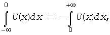
![]()
![]()

Рассмотрим, какое преобразование осуществляет сфероконическая система при условии, что d1=f, d2≠f и ![]()
![]()
При этих условиях выражение (*) примет видUnder these conditions, the expression (*) takes the form

где ![]()
![]()
![]()
![]()
Если х≪f, то в этом случае выражением типа формула Френеля под оператором Фурье можно пренебречь и поле в плоскости объекта с точностью до соответствующих фазовых множителей будет представлять собой сумму спектральных компонент, симметрично расположенных относительно оси системы со сдвигом на ω0.If x≪f, then in this case an expression of the type Fresnel formula under the Fourier operator can be neglected and the field in the plane of the object, up to the corresponding phase factors, will be the sum of spectral components symmetrically located relative to the axis of the system with a shift by ω 0 .
Рассмотрим спектр мощности поля:Consider the power spectrum of the field:
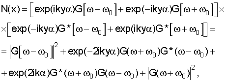
где функция G описывает спектр исходного распределения поля.where the function G describes the spectrum of the initial field distribution.
Очевидно, что при у=0 это выражение можно представить в видеObviously, for y = 0 this expression can be represented as
![]()
![]()
которое представляет собой выражение для мощности суммы спектральных компонент, симметрично расположенных относительно оси системы со сдвигом на ω0.which is an expression for the power of the sum of spectral components symmetrically located relative to the axis of the system with a shift by ω 0 .
Обобщая данное выражение на трехмерный случай, можно прийти к выводу, что распределение поля на оптической оси сфероконической системы представляет собой сумму спектральных компонент, соответствующих мощности светового поля, рассеянного под определенным углом к оптической оси сфероконической системы, определяемого из выражения ω0=k0sinφ, где φ - угол между волновым вектором дифрагированной компоненты и оптической осью сфероконической системы.Generalizing this expression to the three-dimensional case, we can conclude that the field distribution on the optical axis of the spherical system is the sum of spectral components corresponding to the power of the light field scattered at a certain angle to the optical axis of the spherical system, determined from the expression ω 0 = k 0 sinφ where φ is the angle between the wave vector of the diffracted component and the optical axis of the spherical system.
Таким образом, система играет роль конического интегратора. Так как ω0 является функцией положения плоскости регистрации d2, то перемещением точки регистрации вдоль оптической оси системы можно производить измерение углового спектра поля с одновременным интегрированием по азимутальному углу.Thus, the system plays the role of a conical integrator. Since ω 0 is a function of the position of the registration plane d 2 , by moving the registration point along the optical axis of the system, it is possible to measure the angular spectrum of the field with simultaneous integration over the azimuthal angle.
Следует отметить, что интенсивность на произвольной и нулевой пространственной частоте регистрируется одним и тем же фотоприемником, расположенным на оптической оси системы. Нормальное падение освещающего пучка обеспечивает аксиальность спектров и возможность регистрации спектра поля на оптической оси системы. При наличии анизотропии обработки поверхности положение плоскости регистрации может быть выбрано таким образом, что пространственные частоты, соответствующие анизотропии, не совпадут с ω0, что позволяет избежать погрешности измерения, обусловленной анизотропией обработки.It should be noted that the intensity at an arbitrary and zero spatial frequency is recorded by the same photodetector located on the optical axis of the system. The normal incidence of the illuminating beam ensures the axiality of the spectra and the possibility of registering the field spectrum on the optical axis of the system. In the presence of anisotropy of the surface treatment, the position of the registration plane can be chosen so that the spatial frequencies corresponding to the anisotropy do not coincide with ω 0 , which avoids the measurement error due to the anisotropy of the treatment.
Указанные факторы способствуют получению достоверной и более точной оценки интенсивности отраженного излучения на нулевой пространственной частоте и интегральной интенсивности на заданной пространственной частоте.These factors contribute to obtaining a reliable and more accurate estimate of the intensity of the reflected radiation at zero spatial frequency and the integrated intensity at a given spatial frequency.
Оценка среднеквадратичной высоты микронеровностей производится по отношению интегральной интенсивности отраженного излучения на заданной пространственной частоте N3 к интегральной интенсивности отраженного излучения на нулевой пространственной частоте N(ω0). Однако явная форма зависимости среднеквадратичной высоты микронеровностей ![]()
![]()
![]()
![]()
Указанный фактор позволяет повысить точность и достоверность определения среднеквадратичной высоты микронеровностей, в том числе для поверхностей с неизвестной статистикой распределения неоднородностей.The indicated factor makes it possible to increase the accuracy and reliability of determining the root-mean-square height of microroughnesses, including for surfaces with unknown statistics of the distribution of inhomogeneities.
На фигуре 2 изображена оптическая схема заявляемого устройства для определения шероховатости поверхности.The figure 2 shows an optical diagram of the inventive device for determining surface roughness.
Устройство содержит лазер 1, расположенные последовательно по ходу лазерного излучения плоское полупрозрачное зеркало 2, оптическую сфероконическую систему 3, диафрагму 4 и фотоприемник 5, узел 6 перемещения, электрически связанный с измерительным блоком (на фигуре не показан). Позицией 7 обозначена исследуемая поверхность.The device comprises a laser 1, a planar
Полупрозрачное зеркало 2 установлено под углом 45° к оптической оси, проходящей через лазер 1, и под углом 45° к оптической оси, проходящей через оптическую сфероконическую систему 3, диафрагму 4 и фотоприемник 5.The
Диафрагма 4 жестко закреплена на фотоприемнике 5. Фотоприемник 5 установлен с возможностью перемещения вдоль оптической оси, между положениями плоскости регистрации, соответствующими нулевой и выбранной пространственной частоте.The
Исследуемая поверхность 7 установлена перпендикулярно ходу луча лазера 1 в передней фокальной плоскости оптической сфероконической системы 3.The investigated surface 7 is installed perpendicular to the course of the laser beam 1 in the front focal plane of the optical
Устройство работает следующим образом.The device operates as follows.
Лазерный пучок от лазера 1 полупрозрачным плоским зеркалом 2 направляется по нормали на исследуемую поверхность 7. Отраженное от поверхности 7 излучение попадает на оптическую сфероконическую систему 3, которая преобразует рассеянное излучение в излучение, распределение поля которого представляет собой сумму спектральных компонент, соответствующих мощности светового поля, рассеянного под определенным углом к оси системы. Измерительный блок (не показан) дает команду узлу 6 перемещения, который устанавливает фотоприемник 5 с диафрагмой 4 последовательно в плоскости регистрации нулевой пространственной частоты и произвольной пространственной частоты. Интегральные интенсивности N(ω0) и N3, соответствующие нулевой и произвольной пространственной частоте, регистрируются измерительным блоком. В динамическом режиме работы фотоприемник 5 с диафрагмой 4 непрерывно перемещается вдоль оптической оси между плоскостями регистрации, соответствующими нулевой и произвольной пространственной частоте. Интегральная интенсивность N(ω), соответствующая пространственной частоте ω, непрерывно регистрируется измерительным блоком.The laser beam from the laser 1 is transformed by a translucent
Измерительный блок определяет отношение ![]()
![]()
Благодаря оптической сфероконической системе 3 происходит непрерывное аналоговое интегрирование и регистрация интенсивности отраженного излучения на произвольной частоте ω, причем измерение компонент излучения на произвольной пространственной частоте осуществляют одним и тем же фотоприемником 5.Thanks to the optical spherical
Благодаря указанным особенностям регистрации интенсивности отраженных излучений появляется возможность определения статистики распределения неоднородностей поверхности и выбора произвольной пространственной частоты, в наибольшей степени соответствующей диапазону микронеровностей и наличию анизотропии обработки, что позволяет значительно снизить погрешность измерения по сравнению с известными решениями.Owing to the indicated features of recording the intensity of reflected radiation, it becomes possible to determine the statistics of the distribution of surface inhomogeneities and to choose an arbitrary spatial frequency that most closely corresponds to the range of microroughnesses and the presence of anisotropy of the treatment, which can significantly reduce the measurement error compared to known solutions.
Источники информацииInformation sources
1. А.с. СССР №815492, МПК G01В 11/30, опубл. 1981.1. A.S. USSR No. 815492, IPC G01В 11/30, publ. 1981.
2. Заявка Японии №58 - 13842, МПК G01В 11/06, опубл. 1983.2. Japanese application No. 58-13842, IPC G01B 11/06, publ. 1983.
3. Заявка ЕПВ №0101375, МПК G01В 11/30, опубл. 1984 - прототип.3. Application EPO No. 0101375, IPC G01B 11/30, publ. 1984 - prototype.
4. Заявка ФРГ №3232885, МПК G01В 11/30, опубл. 1984 - прототип.4. Application of Germany No. 3232885, IPC G01B 11/30, publ. 1984 - prototype.
Claims (2)
Priority Applications (1)
| Application Number | Priority Date | Filing Date | Title |
|---|---|---|---|
| RU2005121450/28A RU2301400C2 (en) | 2005-07-07 | 2005-07-07 | Mode and arrangement for definition of roughness of a surface |
Applications Claiming Priority (1)
| Application Number | Priority Date | Filing Date | Title |
|---|---|---|---|
| RU2005121450/28A RU2301400C2 (en) | 2005-07-07 | 2005-07-07 | Mode and arrangement for definition of roughness of a surface |
Publications (2)
| Publication Number | Publication Date |
|---|---|
| RU2005121450A RU2005121450A (en) | 2007-01-20 |
| RU2301400C2 true RU2301400C2 (en) | 2007-06-20 |
Family
ID=37774385
Family Applications (1)
| Application Number | Title | Priority Date | Filing Date |
|---|---|---|---|
| RU2005121450/28A RU2301400C2 (en) | 2005-07-07 | 2005-07-07 | Mode and arrangement for definition of roughness of a surface |
Country Status (1)
| Country | Link |
|---|---|
| RU (1) | RU2301400C2 (en) |
Citations (3)
| Publication number | Priority date | Publication date | Assignee | Title |
|---|---|---|---|---|
| EP0101375A1 (en) * | 1982-08-13 | 1984-02-22 | Commissariat à l'Energie Atomique | Method and apparatus for determining without making contact the roughness of a surface |
| SU1700359A1 (en) * | 1989-08-14 | 1991-12-23 | Всесоюзный Научно-Исследовательский Институт Метрологической Службы | Method of measuring standard deviation of anisotropic svrfaces roughness heights |
| RU2180429C2 (en) * | 1996-07-09 | 2002-03-10 | Стариков Сергей Владимирович | Device determining roughness of surface |
-
2005
- 2005-07-07 RU RU2005121450/28A patent/RU2301400C2/en not_active IP Right Cessation
Patent Citations (3)
| Publication number | Priority date | Publication date | Assignee | Title |
|---|---|---|---|---|
| EP0101375A1 (en) * | 1982-08-13 | 1984-02-22 | Commissariat à l'Energie Atomique | Method and apparatus for determining without making contact the roughness of a surface |
| SU1700359A1 (en) * | 1989-08-14 | 1991-12-23 | Всесоюзный Научно-Исследовательский Институт Метрологической Службы | Method of measuring standard deviation of anisotropic svrfaces roughness heights |
| RU2180429C2 (en) * | 1996-07-09 | 2002-03-10 | Стариков Сергей Владимирович | Device determining roughness of surface |
Also Published As
| Publication number | Publication date |
|---|---|
| RU2005121450A (en) | 2007-01-20 |
Similar Documents
| Publication | Publication Date | Title |
|---|---|---|
| US7053991B2 (en) | Differential numerical aperture methods | |
| KR101815325B1 (en) | System for directly measuring the depth of a high aspect ratio etched feature on a wafer | |
| KR102760925B1 (en) | Inspecting apparatus based on hyper HSI(Hyper Spectral Imaging) | |
| CN1226590C (en) | Apparatus for measuring film thickness formed on object, apparatus and method for measuring spectral reflectance of object, and apparatus and method of inspecting foreign material on object | |
| US11262293B2 (en) | System and method for use in high spatial resolution ellipsometry | |
| KR101698022B1 (en) | Achromatic rotating-element ellipsometer and method for measuring Mueller-matirx elements of the sample using the same | |
| US20240183655A1 (en) | Measuring apparatus and method for roughness and/or defect measurement on a surface | |
| US20090290168A1 (en) | Inspecting Method and Inspecting Apparatus for Substrate Surface | |
| JPH04501175A (en) | Surface measurement device and method using ellipsometry | |
| US9829310B2 (en) | Interferometric roll-off measurement using a static fringe pattern | |
| KR20150025745A (en) | Rotating-Element Ellipsometer and method for measuring Mueller-matirx elements of the sample using the same | |
| CN102759332B (en) | Scattering metering device and metering method thereof | |
| CN110082071B (en) | Device and method for measuring optical parallel difference of right-angle prism | |
| CN111664802A (en) | Semiconductor wafer surface morphology measuring device based on dynamic quantitative phase imaging | |
| CN100395538C (en) | A new type of fast ellipsometry system | |
| CN105209852A (en) | Surface-geometry measurement method and device used therein | |
| CN118443672B (en) | Scanning type bright-dark field synchronous interferometry device and method for defects and surface shapes of optical elements | |
| CN111579075A (en) | A fast detection method of light wave polarization state based on Fourier analysis | |
| CN101221042A (en) | Two-dimensional dispersion fringe analysis method for absolute distance measurement | |
| CN111750799B (en) | Device and method for measuring five-dimensional information of spectral polarization topography based on interference illumination | |
| JPH06294629A (en) | Device for measuring curvature of surface | |
| Larichev et al. | An autocollimation null detector: development and use in dynamic goniometry | |
| RU2301400C2 (en) | Mode and arrangement for definition of roughness of a surface | |
| CN110243760A (en) | Line domain frequency domain optical coherence tomography system and its longitudinal coordinate calibration method | |
| Wang | Light-scattering method for characterizing optical surfaces |
Legal Events
| Date | Code | Title | Description |
|---|---|---|---|
| MM4A | The patent is invalid due to non-payment of fees |
Effective date: 20080708 |