RU2144183C1 - Method and system determining density of liquid - Google Patents
Method and system determining density of liquid Download PDFInfo
- Publication number
- RU2144183C1 RU2144183C1 RU96110897A RU96110897A RU2144183C1 RU 2144183 C1 RU2144183 C1 RU 2144183C1 RU 96110897 A RU96110897 A RU 96110897A RU 96110897 A RU96110897 A RU 96110897A RU 2144183 C1 RU2144183 C1 RU 2144183C1
- Authority
- RU
- Russia
- Prior art keywords
- output
- frequency
- signal
- input
- liquid
- Prior art date
Links
- 239000007788 liquid Substances 0.000 title claims abstract description 80
- 238000000034 method Methods 0.000 title claims abstract description 25
- 230000000694 effects Effects 0.000 claims abstract description 5
- 239000012530 fluid Substances 0.000 claims description 19
- 239000000463 material Substances 0.000 claims description 12
- 238000012545 processing Methods 0.000 claims description 7
- 230000010363 phase shift Effects 0.000 claims description 6
- 238000012360 testing method Methods 0.000 claims description 6
- 230000010355 oscillation Effects 0.000 claims description 5
- 238000002604 ultrasonography Methods 0.000 claims description 5
- 239000004065 semiconductor Substances 0.000 claims description 3
- 230000001960 triggered effect Effects 0.000 claims description 2
- 238000005259 measurement Methods 0.000 abstract description 31
- 230000008859 change Effects 0.000 abstract description 7
- 238000009774 resonance method Methods 0.000 abstract description 3
- 239000000126 substance Substances 0.000 abstract description 3
- 238000005516 engineering process Methods 0.000 abstract description 2
- 238000011835 investigation Methods 0.000 abstract 1
- 230000000875 corresponding effect Effects 0.000 description 24
- 230000006870 function Effects 0.000 description 9
- 238000004364 calculation method Methods 0.000 description 8
- 230000001105 regulatory effect Effects 0.000 description 7
- 238000010586 diagram Methods 0.000 description 6
- 238000012935 Averaging Methods 0.000 description 5
- 230000007423 decrease Effects 0.000 description 5
- 101100427576 Caenorhabditis elegans ung-1 gene Proteins 0.000 description 4
- FAPWRFPIFSIZLT-UHFFFAOYSA-M Sodium chloride Chemical compound [Na+].[Cl-] FAPWRFPIFSIZLT-UHFFFAOYSA-M 0.000 description 4
- 238000010521 absorption reaction Methods 0.000 description 4
- XLYOFNOQVPJJNP-UHFFFAOYSA-N water Substances O XLYOFNOQVPJJNP-UHFFFAOYSA-N 0.000 description 4
- PEDCQBHIVMGVHV-UHFFFAOYSA-N Glycerine Chemical compound OCC(O)CO PEDCQBHIVMGVHV-UHFFFAOYSA-N 0.000 description 3
- 230000033228 biological regulation Effects 0.000 description 3
- 230000005284 excitation Effects 0.000 description 3
- VLKZOEOYAKHREP-UHFFFAOYSA-N n-Hexane Chemical compound CCCCCC VLKZOEOYAKHREP-UHFFFAOYSA-N 0.000 description 3
- 230000002411 adverse Effects 0.000 description 2
- 230000032683 aging Effects 0.000 description 2
- 230000006399 behavior Effects 0.000 description 2
- DIKBFYAXUHHXCS-UHFFFAOYSA-N bromoform Chemical compound BrC(Br)Br DIKBFYAXUHHXCS-UHFFFAOYSA-N 0.000 description 2
- 238000006073 displacement reaction Methods 0.000 description 2
- 238000002474 experimental method Methods 0.000 description 2
- 230000010354 integration Effects 0.000 description 2
- 238000012886 linear function Methods 0.000 description 2
- GQYHUHYESMUTHG-UHFFFAOYSA-N lithium niobate Chemical compound [Li+].[O-][Nb](=O)=O GQYHUHYESMUTHG-UHFFFAOYSA-N 0.000 description 2
- 239000011780 sodium chloride Substances 0.000 description 2
- 241000534414 Anotopterus nikparini Species 0.000 description 1
- 238000004458 analytical method Methods 0.000 description 1
- 230000008901 benefit Effects 0.000 description 1
- 230000005540 biological transmission Effects 0.000 description 1
- 229950005228 bromoform Drugs 0.000 description 1
- 230000000052 comparative effect Effects 0.000 description 1
- 238000012733 comparative method Methods 0.000 description 1
- 230000001276 controlling effect Effects 0.000 description 1
- 238000001816 cooling Methods 0.000 description 1
- 230000002596 correlated effect Effects 0.000 description 1
- 239000013078 crystal Substances 0.000 description 1
- 238000000354 decomposition reaction Methods 0.000 description 1
- 238000011161 development Methods 0.000 description 1
- 230000018109 developmental process Effects 0.000 description 1
- 230000008713 feedback mechanism Effects 0.000 description 1
- 238000001914 filtration Methods 0.000 description 1
- -1 for example Substances 0.000 description 1
- 238000010438 heat treatment Methods 0.000 description 1
- 230000003993 interaction Effects 0.000 description 1
- QSHDDOUJBYECFT-UHFFFAOYSA-N mercury Chemical compound [Hg] QSHDDOUJBYECFT-UHFFFAOYSA-N 0.000 description 1
- 229910052753 mercury Inorganic materials 0.000 description 1
- 230000008569 process Effects 0.000 description 1
- 239000010453 quartz Substances 0.000 description 1
- 230000005855 radiation Effects 0.000 description 1
- 230000004044 response Effects 0.000 description 1
- VYPSYNLAJGMNEJ-UHFFFAOYSA-N silicon dioxide Inorganic materials O=[Si]=O VYPSYNLAJGMNEJ-UHFFFAOYSA-N 0.000 description 1
- 230000003595 spectral effect Effects 0.000 description 1
- 230000035882 stress Effects 0.000 description 1
- 230000001360 synchronised effect Effects 0.000 description 1
Images


Classifications
-
- G—PHYSICS
- G01—MEASURING; TESTING
- G01N—INVESTIGATING OR ANALYSING MATERIALS BY DETERMINING THEIR CHEMICAL OR PHYSICAL PROPERTIES
- G01N29/00—Investigating or analysing materials by the use of ultrasonic, sonic or infrasonic waves; Visualisation of the interior of objects by transmitting ultrasonic or sonic waves through the object
- G01N29/02—Analysing fluids
- G01N29/024—Analysing fluids by measuring propagation velocity or propagation time of acoustic waves
-
- G—PHYSICS
- G01—MEASURING; TESTING
- G01N—INVESTIGATING OR ANALYSING MATERIALS BY DETERMINING THEIR CHEMICAL OR PHYSICAL PROPERTIES
- G01N29/00—Investigating or analysing materials by the use of ultrasonic, sonic or infrasonic waves; Visualisation of the interior of objects by transmitting ultrasonic or sonic waves through the object
- G01N29/02—Analysing fluids
- G01N29/036—Analysing fluids by measuring frequency or resonance of acoustic waves
-
- G—PHYSICS
- G01—MEASURING; TESTING
- G01N—INVESTIGATING OR ANALYSING MATERIALS BY DETERMINING THEIR CHEMICAL OR PHYSICAL PROPERTIES
- G01N29/00—Investigating or analysing materials by the use of ultrasonic, sonic or infrasonic waves; Visualisation of the interior of objects by transmitting ultrasonic or sonic waves through the object
- G01N29/22—Details, e.g. general constructional or apparatus details
- G01N29/30—Arrangements for calibrating or comparing, e.g. with standard objects
-
- G—PHYSICS
- G01—MEASURING; TESTING
- G01N—INVESTIGATING OR ANALYSING MATERIALS BY DETERMINING THEIR CHEMICAL OR PHYSICAL PROPERTIES
- G01N29/00—Investigating or analysing materials by the use of ultrasonic, sonic or infrasonic waves; Visualisation of the interior of objects by transmitting ultrasonic or sonic waves through the object
- G01N29/34—Generating the ultrasonic, sonic or infrasonic waves, e.g. electronic circuits specially adapted therefor
- G01N29/348—Generating the ultrasonic, sonic or infrasonic waves, e.g. electronic circuits specially adapted therefor with frequency characteristics, e.g. single frequency signals, chirp signals
-
- G—PHYSICS
- G01—MEASURING; TESTING
- G01N—INVESTIGATING OR ANALYSING MATERIALS BY DETERMINING THEIR CHEMICAL OR PHYSICAL PROPERTIES
- G01N29/00—Investigating or analysing materials by the use of ultrasonic, sonic or infrasonic waves; Visualisation of the interior of objects by transmitting ultrasonic or sonic waves through the object
- G01N29/36—Detecting the response signal, e.g. electronic circuits specially adapted therefor
- G01N29/42—Detecting the response signal, e.g. electronic circuits specially adapted therefor by frequency filtering or by tuning to resonant frequency
-
- G—PHYSICS
- G01—MEASURING; TESTING
- G01N—INVESTIGATING OR ANALYSING MATERIALS BY DETERMINING THEIR CHEMICAL OR PHYSICAL PROPERTIES
- G01N9/00—Investigating density or specific gravity of materials; Analysing materials by determining density or specific gravity
- G01N9/002—Investigating density or specific gravity of materials; Analysing materials by determining density or specific gravity using variation of the resonant frequency of an element vibrating in contact with the material submitted to analysis
-
- G—PHYSICS
- G01—MEASURING; TESTING
- G01N—INVESTIGATING OR ANALYSING MATERIALS BY DETERMINING THEIR CHEMICAL OR PHYSICAL PROPERTIES
- G01N2291/00—Indexing codes associated with group G01N29/00
- G01N2291/01—Indexing codes associated with the measuring variable
- G01N2291/012—Phase angle
-
- G—PHYSICS
- G01—MEASURING; TESTING
- G01N—INVESTIGATING OR ANALYSING MATERIALS BY DETERMINING THEIR CHEMICAL OR PHYSICAL PROPERTIES
- G01N2291/00—Indexing codes associated with group G01N29/00
- G01N2291/02—Indexing codes associated with the analysed material
- G01N2291/028—Material parameters
- G01N2291/02818—Density, viscosity
Landscapes
- Physics & Mathematics (AREA)
- Biochemistry (AREA)
- Health & Medical Sciences (AREA)
- Life Sciences & Earth Sciences (AREA)
- Chemical & Material Sciences (AREA)
- Analytical Chemistry (AREA)
- General Health & Medical Sciences (AREA)
- General Physics & Mathematics (AREA)
- Immunology (AREA)
- Pathology (AREA)
- Acoustics & Sound (AREA)
- Investigating Or Analyzing Materials By The Use Of Ultrasonic Waves (AREA)
- Apparatuses For Generation Of Mechanical Vibrations (AREA)
Abstract
Description
Изобретение относится к способу и системе для определения плотности жидкости ультразвуковыми методами и более конкретно к определению плотности образца жидкости. The invention relates to a method and system for determining the density of a liquid by ultrasonic methods, and more particularly to determining the density of a liquid sample.
Во многих областях науки и техники очень важно знать зависимость объема жидкости от давления и/или температуры ("данные P-V-T"). На основании данных P-V-T составляется соответствующее уравнение состояния конденсируемого вещества, в частности, жидкостей, полностью описывающее его термодинамические характеристики. In many areas of science and technology, it is very important to know the dependence of fluid volume on pressure and / or temperature ("P-V-T data"). Based on the P-V-T data, the corresponding equation of state of the condensed substance, in particular, liquids, is fully described fully describing its thermodynamic characteristics.
В настоящее время известны различные методы измерения данных P-V-T. Особенно хорошие результаты дают ультразвуковые методы, которые по равнению с большинством других методов позволяют существенно повысить точность получаемых данных, поскольку скорость звука в конденсируемом веществе может быть определена с точностью порядка 10-6.Various methods for measuring PVT data are currently known. Ultrasonic methods give particularly good results, which, in comparison with most other methods, can significantly increase the accuracy of the data obtained, since the speed of sound in a condensed substance can be determined with an accuracy of the order of 10 -6 .
Ультразвуковые методы определения характеристик материала в принципе основаны на измерении скорости и необязательно затухания ультразвуковых волн в исследуемом при различных давлениях и температурах материале. Адиабатическая сжимаемость материала непосредственно коррелируется со скоростью звука, и поэтому данные P-V-T материала могут быть получены путем измерения скорости звуковых волн, в частности ультразвуковых волн, при различных давлениях и температурах, если известно абсолютное значение плотности исследуемого материала при заданной температуре и нормальном давлении. Ultrasonic methods for determining the characteristics of a material are in principle based on measuring the speed and optionally attenuation of ultrasonic waves in a material studied at various pressures and temperatures. The adiabatic compressibility of the material is directly correlated with the speed of sound, and therefore the P-V-T data of the material can be obtained by measuring the speed of sound waves, in particular ultrasonic waves, at various pressures and temperatures, if the absolute density of the material under study at a given temperature and normal pressure is known.
Акустический импеданс Z жидкости является функцией ее плотности ρ и скорости c звука в жидкости:
Z = ρc. (1)
Акустические резонансы fn слоя исследуемой жидкости в акустической резонансной камере (кратко "жидкостные резонансы") и резонансы излучателя и приемника камеры (предполагается, что они равны) на основных частотах f0 и их гармониках накладываются друг на друга, вызывая взаимодействие самих резонансов. При этом отражение звуковых волн в ультразвуковом резонаторе на границах раздела между преобразователями и жидкостью является функцией акустического импеданса Z жидкости и акустического импеданса Z0 материала преобразователя.The acoustic impedance Z of a fluid is a function of its density ρ and sound velocity c in the fluid:
Z = ρc. (1)
Acoustic resonances f n the sample liquid layer in an acoustic resonator cell (in short "liquid resonances") and resonances of the emitter and receiver chamber (assuming that they are equal) at the fundamental frequency f 0 and its harmonics are superimposed on each other, causing the interaction of these resonances. In this case, the reflection of sound waves in the ultrasonic resonator at the interfaces between the transducers and the liquid is a function of the acoustic impedance Z of the liquid and the acoustic impedance Z 0 of the material of the transducer.
Эффекты наложения частот зависят, с одной стороны, от разницы собственной частоты преобразователя и соответствующей собственной частоты жидкости, а, с другой стороны, от акустических импедансов исследуемой жидкости и материала преобразователя. The effects of superposition of frequencies depend, on the one hand, on the difference between the natural frequency of the converter and the corresponding natural frequency of the liquid, and, on the other hand, on the acoustic impedances of the studied liquid and the material of the converter.
Более тщательные теоретические исследования поведения ультразвукового резонатора показали, что для преобразователя, на обратной стороне которого находится воздух, условия отражения собственных частот жидкости fn ≈ nfπ (fπ = f0/2) почти идеальны, т.е. амплитуды и фазы резонансов жидкости практически не зависят от резонансов преобразователей. Благодаря этому упрощается расчет значений скорости и поглощения звука в исследуемой жидкости на этих частотах.More thorough theoretical studies of the behavior of the ultrasonic resonator showed that for a transducer on the reverse side of which there is air, the conditions for the reflection of the eigenfrequencies of the liquid f n ≈ nf π (f π = f 0/2 ) are almost ideal, i.e. the amplitudes and phases of the resonances of the liquid are practically independent of the resonances of the transducers. This simplifies the calculation of the values of velocity and sound absorption in the investigated fluid at these frequencies.
Однако на резонансы жидкости, близкие к собственной частоте преобразователей, отрицательно влияют неидеальные условия отражения звуковой волны. Этой проблеме посвящено большое количество теоретических исследований. Во всех этих исследованиях влияние условий неидеального отражения на резонансы жидкости рассматривается, с одной стороны, в зависимости от акустических импедансов жидкости и материала преобразователя, а, с другой стороны, в зависимости от расстояния собственной частоты жидкости до резонансной частоты преобразователя (см., например, A. P. Sarvazyan, Т. V. Chalikian, Ultrasonics 29 (1991) 119-124). Если акустический импеданс материала преобразователя известен, то импеданс жидкости и, следовательно, ее плотность могут быть вычислены по изменениям резонансов жидкости, обусловленным неидеальными условиями отражения. However, liquid resonances close to the natural frequency of the transducers are adversely affected by imperfect conditions for the reflection of a sound wave. A large number of theoretical studies have been devoted to this problem. In all these studies, the influence of non-ideal reflection conditions on liquid resonances is considered, on the one hand, depending on the acoustic impedances of the liquid and the transducer material, and, on the other hand, depending on the distance of the natural frequency of the liquid to the resonant frequency of the transducer (see, for example, AP Sarvazyan, T. V. Chalikian, Ultrasonics 29 (1991) 119-124). If the acoustic impedance of the transducer material is known, then the impedance of the liquid and, therefore, its density can be calculated from changes in the resonances of the liquid due to non-ideal reflection conditions.
Sarvazyan и Chalikian предложили также аппаратуру для ультразвуковых измерений параметров жидкости. Эта аппаратура имеет ультразвуковую резонансную камеру с двумя электроакустическими преобразователями, образующими по крайней мере одну резонансную полость, заполненную исследуемой жидкостью. Резонансная камера помещается в сосуд, где находится жидкость под давлением, под действием которой в исследуемой жидкости и на обратных сторонах преобразователей создается избыточное давление. Sarvazyan and Chalikian also proposed equipment for ultrasonic measurements of fluid parameters. This equipment has an ultrasonic resonance chamber with two electro-acoustic transducers forming at least one resonant cavity filled with the test fluid. The resonance chamber is placed in the vessel where the liquid is under pressure, under the influence of which excess pressure is created in the liquid under study and on the reverse sides of the transducers.
Система, включающая ультразвуковую резонансную камеру и электронную схему измерения параметров конденсируемого материала, в частности жидкости, описана в WO 92/03723 (авторы Sarvazyan, Belonenko и Chalikian), которая включена в настоящую заявку в качестве ссылки. В этой системе измерений отсутствуют элементы, позволяющие выбрать конкретный резонансный максимум ультразвуковой резонансной камеры, на который синхронизирован управляемый напряжением генератор (далее УНГ). Фактически сдвиг фаз при фазовой синхронизации происходит на многих частотах, поскольку фазочастотная характеристика резонансной камеры периодически повторяется (период 2π для ее четных и нечетных гармоник собственной частоты. В известной схеме отсутствуют также устройства для многочастотного разложения конкретного резонансного максимума для определения его амплитудно-частотной характеристики. A system including an ultrasonic resonance chamber and an electronic circuit for measuring parameters of a condensable material, in particular a liquid, is described in WO 92/03723 (authors Sarvazyan, Belonenko and Chalikian), which is incorporated herein by reference. There are no elements in this measurement system that make it possible to select a specific resonance maximum of the ultrasonic resonance chamber to which the voltage-controlled oscillator (hereinafter referred to as UNG) is synchronized. In fact, the phase shift during phase synchronization occurs at many frequencies, since the phase-frequency characteristic of the resonance chamber is periodically repeated (period 2π for its even and odd harmonics of the natural frequency. There are also no devices for multi-frequency decomposition of a specific resonance maximum to determine its amplitude-frequency characteristic.
В патенте SU-A-68437 описана возможность определения плотности жидкости по спектральному составу ее собственных частот на основе полуэмпирических зависимостей. При использовании таких зависимостей требуется измерение резонансных частот исследуемой жидкости вблизи собственной частоты преобразователя при значительном снижении добротности резонансов, т.е. при чрезмерном расширении их пиков. При этом ограничивается точность измерения резонансных частот, а полученные таким методом значения плотности не позволяют определить данные P-V-T исследуемой жидкости с необходимой высокой точностью. Очевидно, однако, что без точного определения плотности исследуемой жидкости нельзя получить достоверные данные P-V-T этой жидкости. The patent SU-A-68437 describes the possibility of determining the density of a liquid from the spectral composition of its natural frequencies based on semi-empirical dependencies. When using these dependences, it is necessary to measure the resonant frequencies of the investigated liquid near the natural frequency of the converter with a significant decrease in the quality factor of resonances, i.e. with excessive expansion of their peaks. At the same time, the accuracy of measuring resonant frequencies is limited, and the density values obtained by this method do not allow determining the P-V-T data of the studied liquid with the required high accuracy. It is obvious, however, that without accurate determination of the density of the test fluid, reliable P-V-T data of this fluid cannot be obtained.
Задачей настоящего изобретения является, таким образом, разработка новых способа и аппаратуры для точного определения плотности жидкости ультразвуковым резонансным методом. The objective of the present invention is, therefore, the development of new methods and apparatus for accurately determining the density of a liquid by ultrasonic resonance method.
Другой задачей настоящего изобретения является разработка способов и аппаратуры для автоматического измерения P-V-T параметров жидкостей, в том числе абсолютного значения плотности жидкости, ультразвуковым резонансным методом. Another objective of the present invention is to develop methods and apparatus for the automatic measurement of P-V-T parameters of liquids, including the absolute value of the density of a liquid, by ultrasonic resonance method.
Указанные задачи решаются с помощью предлагаемого в изобретении способа определения плотности жидкости, основанного на исследовании резонансного поведения пробы жидкости в ультразвуковой резонансной камере, имеющей излучающий ультразвук преобразователь и оппозитный ему принимающий ультразвук преобразователь и в пространстве между ними полость для пробы исследуемой жидкости, путем создания в ней ультразвуковых волн переменной частоты, включающий заполнение полости резонансной камеры эталонной жидкостью, выбор по крайней мере одной резонансной частоты fn0 ультразвуковых волн из множества таких резонансных частот в заданном частотном диапазоне, превышающей пороговую частоту flim резонансной камеры, выше которой эффектами дифракции ультразвуковых волн в камере можно пренебречь, заполнение полости резонансной камеры пробой исследуемой жидкости, создание ультразвуковых волн с выбранной резонансной частотой fn0 в этой пробе подачей сигнала ультразвуковой частоты на излучающий преобразователь. Согласно изобретению, изменяют сдвиг θ по фазе между поданным сигналом и выходным сигналом, снимаемым с принимающего преобразователя, для определения первого значения частоты fn, которому соответствует максимальное значение амплитуды ультразвуковых волн в заполненной пробой резонансной камере, и второго fn1 и третьего fn2 значений частоты, при которых величина амплитуды ультразвуковых волн меньше указанного максимального значения, определяют значение ширины полосы частот на уровне половинной мощности Δfn= fn1-fn2, по значению Δfn определяют значения потерь Lrefl, которые имеют место вблизи собственных частот преобразователей, связанных с неидеальными условиями отражения волн на поверхностях преобразователей, а затем определяют
-ln(cosθ) = π•d•fn•Lrefl/c,
где c - скорость звука в жидкости,
d - расстояние между преобразователями,
затем, зная эту величину, определяют коэффициент J по соответствующей функции зависимости коэффициента J от значений -ln(cosθ) или с помощью числовой таблицы, после чего вычисляют отношение акустических импедансов z по формуле
z = J•tg(π•fn/fo),
где f0 - основная собственная частота преобразователей, и искомое значение плотности определяют из соотношения
ρ = Zo•z/c,
где Z0 - акустический импеданс материала преобразователя.These problems are solved using the method of determining the density of a liquid, proposed in the invention, based on the study of the resonant behavior of a liquid sample in an ultrasonic resonant chamber having an ultrasound emitting transducer and an opposite transducer receiving ultrasound transducer and in the space between them a cavity for a sample of the studied liquid, by creating ultrasonic waves of variable frequency, including filling the cavity of the resonant chamber with a reference fluid, at least one choice th resonance frequency f n0 ultrasonic waves of a plurality of resonant frequencies in a predetermined frequency range above the threshold frequency f lim resonant chamber, above which the effects of diffraction of ultrasonic waves in the chamber can be neglected, filling the cavity resonance chamber test liquid sample, creating ultrasonic waves from the selected resonator frequency f n0 in this sample by applying an ultrasonic frequency signal to the emitting transducer. According to the invention, the phase shift θ is changed between the supplied signal and the output signal taken from the receiving transducer to determine the first value of the frequency f n , which corresponds to the maximum value of the amplitude of the ultrasonic waves in the filled resonance chamber, and the second f n1 and third f n2 values the frequencies at which the magnitude of the amplitude of the ultrasonic waves is less than the specified maximum value, determine the value of the bandwidth at half power level Δf n = f n1 -f n2 , from the value Δf n defined the loss values L refl , which take place near the natural frequencies of the transducers associated with non-ideal conditions for the reflection of waves on the surfaces of the transducers, are then determined
-ln (cosθ) = π • d • f n • L refl / c,
where c is the speed of sound in a liquid,
d is the distance between the transducers,
then, knowing this value, determine the coefficient J by the corresponding function of the dependence of the coefficient J on the values -ln (cosθ) or using a numerical table, after which the ratio of acoustic impedances z is calculated by the formula
z = J • tg (π • f n / f o ),
where f 0 is the fundamental natural frequency of the converters, and the desired density value is determined from the relation
ρ = Z o • z / c,
where Z 0 is the acoustic impedance of the transducer material.
Система для реализации способа включает управляемый напряжением генератор изменяемой частоты с управляющим входом, ультразвуковую резонансную камеру с множеством собственных частот, снабженную электроакустическим излучающим преобразователем, вход которого соединен с выходом генератора, и оппозитным ему электроакустическим принимающим преобразователем и расположенной между преобразователями полостью для пробы жидкости, схему фазовой синхронизации, которая подключена между выходом принимающего преобразователя и управляющим входом генератора, устройство реагирования на выходной сигнал принимающего преобразователя, устройство, подключенное к схеме фазовой синхронизации для управления и изменения фазы подаваемого на излучающий преобразователь сигнала относительно выходного сигнала принимающего преобразователя. Согласно изобретению в системе предусмотрены управляющее устройство, подключенное к схеме фазовой синхронизации для ввода в нее управляющего напряжения при настройке частоты генератора на любую требуемую частоту из всего множества собственных частот резонансной камеры, и вычислительный блок для вычисления плотности. The system for implementing the method includes a voltage-controlled variable frequency generator with a control input, an ultrasonic resonance chamber with many natural frequencies, equipped with an electro-acoustic emitting transducer, the input of which is connected to the output of the generator, and an opposed electro-acoustic receiving transducer and a cavity for liquid sample located between the transducers, a circuit phase synchronization, which is connected between the output of the receiving transducer and the control input ohm generator device response to an output signal of the receiving transducer, the device connected to the phase synchronization circuit for control and phase change applied to the emitting transducer signal relative to the receiving transducer output signal. According to the invention, a control device is provided in the system that is connected to a phase synchronization circuit for inputting a control voltage into it when the generator frequency is tuned to any desired frequency from the whole set of natural frequencies of the resonance chamber, and a computing unit for density calculation.
В предпочтительной форме выполнения системы ее схема фазовой синхронизации содержит фазовый компаратор, имеющий первый вход, соединенный с принимающим преобразователем, второй вход, соединенный с выходом УНГ, и выход, цепь обратной связи, соединяющую выход фазового компаратора с управляющим входом УНГ и формирующую при этом схему фазовой синхронизации, и устройство для отключения схемы фазовой синхронизации. In a preferred embodiment of the system, its phase synchronization circuit comprises a phase comparator having a first input connected to the receiving transducer, a second input connected to the output of the UNG, and an output, a feedback circuit connecting the output of the phase comparator to the control input of the UNG and forming a circuit phase synchronization, and a device for disabling the phase synchronization circuit.
Устройство для отключения схемы фазовой синхронизации в свою очередь имеет устройство для размыкания цепи обратной связи. The device for disabling the phase synchronization circuit, in turn, has a device for opening the feedback circuit.
Цепь обратной связи в одном из вариантов реализации содержит интегратор, имеющий вход, соединенный с выходом фазового компаратора, выход, соединенный с управляющим входом УНГ, и управляющий вход, соединенный с устройством для возвращения интегратора в исходное положение, на выходе которого при этом создается постоянное напряжение. The feedback circuit in one embodiment includes an integrator having an input connected to the output of the phase comparator, an output connected to the control input of the UNG, and a control input connected to a device to return the integrator to its original position, the output of which creates a constant voltage .
Желательно также, когда рассматриваемая система включает в себя устройство для создания первого регулируемого напряжения и устройство, которое складывает это первое регулируемое напряжение с сигналом на выходе из фазового компаратора. It is also desirable when the system in question includes a device for generating a first controlled voltage and a device that adds up this first controlled voltage with a signal at the output of the phase comparator.
Желательно также иметь в системе устройство для создания второго регулируемого напряжения и устройство, которое складывает это второе регулируемое напряжение с выходным напряжением интегратора. It is also desirable to have in the system a device for generating a second regulated voltage and a device that adds this second adjustable voltage to the output voltage of the integrator.
Предпочтительна также система, включающая устройство измерения частоты, соединенное с выходом УНГ и содержащее генератор для создания отпирающего импульса, определяющего интервал считывания, и устройство для считывания количества колебаний напряжения, генерируемого УНГ в течение интервала считывания, при этом считывающее устройство имеет устройство для вычисления измеряемой частоты по количеству колебаний напряжения и интервалу считывания. It is also preferable that the system includes a frequency measuring device connected to the output of the UNG and containing a generator for generating a trigger pulse that determines the reading interval, and a device for reading the number of voltage fluctuations generated by the UNG during the reading interval, while the reader has a device for calculating the measured frequency by the number of voltage fluctuations and the reading interval.
При этом генератор отпирающих импульсов содержит стабилизированный генератор и предварительно настраиваемый счетчик для считывания предварительно заданного количества колебаний сигнала стабилизированного генератора и генерирования во время считывания выходного импульса, определяющего интервал считывания, а также содержит синхронизирующую триггерную схему, соединенную с выходом стабилизированного генератора и запускаемую колебаниями его напряжения и имеющую выход, соединенный с запускающим входом счетчика с предварительной установкой, который начинает считывать импульсы только в течение промежутка времени, определяемого периодом колебаний сигнала стабилизированного генератора, при этом синхронизирующая триггерная схема имеет разрешающий вход, на который подается разрешающий сигнал. In this case, the trigger pulse generator comprises a stabilized generator and a pre-configured counter for reading a predetermined number of oscillations of the stabilized generator signal and generating an output pulse that determines the reading interval during reading, and also contains a synchronizing trigger circuit connected to the output of the stabilized generator and triggered by fluctuations in its voltage and having an output connected to the starting input of the counter with a preliminary anovkoy which starts reading pulses only in the determined period of the stabilized oscillation signal generator for a time interval, wherein the synchronizing circuit has a trigger enabling input to which is applied the enable signal.
Систему целесообразно оснастить устройством измерения амплитуды, соединенным с выходом принимающего преобразователя. It is advisable to equip the system with an amplitude measuring device connected to the output of the receiving transducer.
В одной из форм выполнения указанное устройство измерения амплитуды включает устройство ограничения амплитуды, вход которого соединен с выходом принимающего преобразователя, и умножитель, имеющий первый вход, соединенный с выходом принимающего преобразователя, и второй вход, принимающий с выхода устройства ограничения амплитуды синусоидальный сигнал, который перемножается с выходным сигналом принимающего преобразователя с получением однонаправленного перемноженного выходного сигнала, который подается в устройство обработки сигнала, включающего аналого-цифровой преобразователь и создающего характеризующий измеряемую амплитуду сигнал. In one embodiment, said amplitude measuring device includes an amplitude limiting device, the input of which is connected to the output of the receiving transducer, and a multiplier having a first input connected to the output of the receiving transducer, and a second input receiving an sinusoidal signal that multiplies from the output of the amplitude limiting device with the output signal of the receiving transducer with obtaining a unidirectional multiplied output signal, which is supplied to the signal processing device la that includes an analog-digital converter and generating a signal characterizing the measured amplitude.
Система, кроме того, содержит устройство для избирательного соединения входа аналого-цифрового преобразователя, которым снабжено устройство обработки сигнала, с выходом интегратора и получения характеризующего фазу сигнала. The system also includes a device for selectively connecting the input of an analog-to-digital converter, which is equipped with a signal processing device, with the output of an integrator and obtaining a phase-characterizing signal.
Еще в одном предпочтительном варианте реализации система имеет несколько акустических резонансных камер, выборочно включаемых в цепь обратной связи между УНГ и фазовым компаратором с помощью селекторного переключателя, содержащего два коммутатора, один из которых имеет один вход и несколько выходов, соединенных с излучающими преобразователями резонансных камер, а другой имеет такое же количество входов, соединенных с принимающими преобразователями резонансных камер, и выход, соединенный с фазовым компаратором. In another preferred embodiment, the system has several acoustic resonance chambers selectively included in the feedback circuit between the UNG and the phase comparator using a selector switch containing two switches, one of which has one input and several outputs connected to the radiating transducers of the resonant chambers, and the other has the same number of inputs connected to the receiving transducers of the resonant chambers, and an output connected to a phase comparator.
Следует отметить, что выход второго коммутатора соединен с фазовым компаратором через устройство ограничения амплитуды. It should be noted that the output of the second switch is connected to the phase comparator through an amplitude limiting device.
Причем одна из акустических резонансных камер системы представляет собой эталонную камеру, определяющую исходное состояние системы, а по меньшей мере одна резонансная камера погружена в сосуд с жидкостью под избыточным давлением, в котором может быть размещен полупроводниковый резонатор. Moreover, one of the acoustic resonance chambers of the system is a reference chamber that determines the initial state of the system, and at least one resonance chamber is immersed in a vessel with liquid under excess pressure, in which a semiconductor resonator can be placed.
Система в одном из вариантов выполнения может быть также снабжена преобразователем, импеданс которого зависит от воздействующих на него механических вибраций, механически соединенным с сосудом, чтобы измерять изменения акустического резонанса сосуда при различных уровнях возникающих в нем механических напряжений. In one embodiment, the system can also be equipped with a transducer, the impedance of which depends on the mechanical vibrations acting on it, mechanically connected to the vessel in order to measure changes in the acoustic resonance of the vessel at various levels of mechanical stresses arising in it.
Указанный преобразователь может быть соединен также с импедансным мостом, определяющим изменения импеданса этого преобразователя, вызванные изменениями резонанса сосуда, а выходной сигнал импедансного моста, характеризующий резонанс сосуда, подается на схему запоминания и контроля, контролирующую состояние системы. The specified Converter can also be connected with an impedance bridge, which determines the changes in the impedance of this Converter, caused by changes in the resonance of the vessel, and the output signal of the impedance bridge, characterizing the resonance of the vessel, is fed to the memory and control circuit that monitors the state of the system.
Согласно изобретению предложена более точная процедура определения плотностей жидких проб, основанная на анализе добротностей резонансов исследуемой жидкости. Добротности резонансов жидкости определяются в зависимости от значений ширины полосы частот на уровне половинной мощности (ШПЧПМ) Δfn, которые определяются амплитудно-частотными или фазочастотными характеристиками резонансных пиков жидкости. Даже для широких резонансов, когда определение частоты максимальной амплитуды затруднено, значение амплитуды Amax при максимальном резонансе может быть определено с высокой точностью путем усреднения и снижения шума вблизи максимального резонанса. Частоты f' и f'', при которых значение амплитуды по разные стороны от максимального резонанса составляет 0,707 Amax (или другую соответствующую величину) можно измерить с достаточной точностью, поскольку резонансная кривая при этих значениях амплитуды обладает достаточной крутизной. Поэтому точность определения значения Δfn не зависит от точности прямого измерения резонансной частоты fn. Повысить точность определения резонансной частоты можно путем арифметического усреднения значений ширины полосы частот на уровне половинной мощности при расположении резонансного пика симметрично над значениями амплитуды, равными 0,707 Amax.According to the invention, a more accurate procedure for determining the density of liquid samples, based on the analysis of the quality factors of the resonances of the investigated fluid. The quality factors of the resonances of the liquid are determined depending on the values of the frequency bandwidth at the half power level (SHPCM) Δf n , which are determined by the amplitude-frequency or phase-frequency characteristics of the resonant peaks of the liquid. Even for wide resonances, when determining the frequency of the maximum amplitude is difficult, the value of the amplitude A max at maximum resonance can be determined with high accuracy by averaging and reducing noise near the maximum resonance. Frequencies f 'and f'', at which the amplitude value on opposite sides of the maximum resonance is 0.707 A max (or another corresponding value) can be measured with sufficient accuracy, since the resonance curve at these amplitude values has a sufficient slope. Therefore, the accuracy of determining the value of Δf n does not depend on the accuracy of direct measurement of the resonant frequency f n . The accuracy of determining the resonant frequency can be improved by arithmetic averaging of the bandwidth at half power when the resonance peak is located symmetrically above the amplitude values of 0.707 A max .
Добротности резонансов жидкости являются производными значений ширины полосы частот на уровне половинной мощности (ШПЧПМ) Δfn или при других соответствующих уровнях мощности, которые определяются по амплитудно-частотным характеристикам резонансных пиков жидкости. Для определения центральной частоты и добротности резонанса можно использовать также и фазочастотные характеристики резонансов. Положение наиболее крутого участка фазочастотной характеристики соответствует центру резонанса, а угол наклона фазовой характеристики является прямой функцией добротности резонанса.The quality factors of the resonances of the liquid are derived from the values of the frequency bandwidth at the half power level (SHPPM) Δf n or at other corresponding power levels, which are determined by the amplitude-frequency characteristics of the resonant peaks of the liquid. To determine the center frequency and the quality factor of the resonance, the phase-frequency characteristics of the resonances can also be used. The position of the steepest section of the phase-frequency characteristic corresponds to the center of the resonance, and the slope of the phase characteristic is a direct function of the quality factor of the resonance.
Изобретение далее поясняется описанием примеров выполнения и чертежами, где
на фиг. 1 показаны кривые зависимости от частоты составляющих потерь в ультразвуковой резонансной камере,
на фиг. 2 - график функции, используемой в предлагаемом способе,
на фиг. 3 - схема, иллюстрирующая на конкретном примере предлагаемый в изобретении способ,
на фиг. 4 - схема, частично в разрезе и частично в виде блок-схемы, ультразвуковой измерительной системы, с помощью которой может быть осуществлено настоящее изобретение,
на фиг. 5 - блок-схема электронной аппаратуры, используемой в системе, показанный на фиг. 4,
на фиг. 6 - алгоритм операций, выполняемых в соответствии с одним из вариантов предлагаемого в изобретении способа,
на фиг. 7-9 - другие варианты ультразвуковых измерительных систем, с помощью которых может быть осуществлено настоящее изобретение.The invention is further illustrated by the description of examples and drawings, where
in FIG. 1 shows the curves as a function of the frequency of the loss components in an ultrasonic resonance chamber,
in FIG. 2 is a graph of the function used in the proposed method,
in FIG. 3 is a diagram illustrating a concrete example of a method according to the invention,
in FIG. 4 is a diagram, partially in section and partially in the form of a block diagram, of an ultrasonic measuring system with which the present invention can be implemented,
in FIG. 5 is a block diagram of electronic equipment used in the system shown in FIG. 4,
in FIG. 6 is a flow chart of operations performed in accordance with one embodiment of the method of the invention,
in FIG. 7-9 are other variants of ultrasonic measuring systems with which the present invention can be practiced.
Ниже под термином "ультразвуковой жидкостной резонатор" понимается ультразвуковой резонатор, содержащий пару плоских круглых, имеющих форму диска электроакустических преобразователей равного диаметра, расположенных параллельно друг другу на некотором расстоянии друг от друга и образующих полость, которая заполняется пробой жидкости; такой резонатор описан, например, в находящейся на рассмотрении PCT/EP93/02113, включенной в настоящую заявку в качестве ссылки. Below, the term "ultrasonic liquid resonator" means an ultrasonic resonator containing a pair of flat circular, disk-shaped electro-acoustic transducers of equal diameter, parallel to each other at a certain distance from each other and forming a cavity that is filled with a liquid sample; such a resonator is described, for example, in pending PCT / EP93 / 02113, incorporated herein by reference.
Ультразвуковые жидкостные резонаторы характеризуются следующими параметрами:
r0 - эффективный радиус преобразователей;
d - расстояние между преобразователями (равно длине пути ультразвуковых волн в полости);
f0 - основная собственная частота преобразователей (предполагается равной для обоих преобразователей);
fn - частота максимальной амплитуды n-го жидкостного резонанса;
Δfn - ШПЧПМ жидкостного резонанса при частоте fn;
Qn - добротность Q резонанса на частоте fn:Qn = fn/Δfn;
λ - длина ультразвуковой волны в полости.Ultrasonic liquid resonators are characterized by the following parameters:
r 0 is the effective radius of the transducers;
d is the distance between the transducers (equal to the path length of the ultrasonic waves in the cavity);
f 0 is the fundamental natural frequency of the converters (assumed to be equal for both converters);
f n is the frequency of the maximum amplitude of the n-th liquid resonance;
Δf n - SHPPM liquid resonance at a frequency f n ;
Q n - Q factor of resonance at a frequency f n : Q n = f n / Δf n ;
λ is the length of the ultrasonic wave in the cavity.
Потери в ультразвуковом жидкостном резонаторе на резонансной частоте fn, которые можно определить как:
Ln = 1/Qn = Δfn/fn (2)
являются суммой четырех следующих составляющих потерь, которые складываются друг с другом и могут быть оценены количественно:
(I) Потери Labs, обусловленные поглощением волн в пробе жидкости. Для жидкостей, которые в исследуемом диапазоне частот не проявляют релаксации, эта составляющая потерь является линейной функцией частоты fn.Losses in the ultrasonic liquid resonator at the resonant frequency f n , which can be defined as:
L n = 1 / Q n = Δf n / f n (2)
are the sum of the four following loss components that add up to each other and can be quantified:
(I) Losses L abs due to the absorption of waves in the sample fluid. For liquids that do not show relaxation in the studied frequency range, this loss component is a linear function of the frequency f n .
(II) Потери Ldiff связаны с дифракцией в диапазоне низких частот, когда поглощение звука мало, и поэтому расстояние, которое проходят звуковые волны в резонаторе, сравнительно велико. Кроме того, в диапазоне низких частот излучение от преобразователей существенно зависит от характеристик звукового поля, которые в свою очередь зависят от отношения r0 и λ. Эта составляющая потерь быстро падает при увеличении частоты с более сложной, чем Labs зависимостью от fn. Отличительным признаком этой зависимости является то, что Ldiff практически снижается до нуля при предельной, частоте flim, которой характеризуется каждый резонатор и которую можно вычислить, зная r0, с и коэффициент поглощения звука α пробы исследуемой жидкости, по следующей формуле:
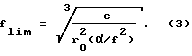
(III) Еще одна составляющая потерь (Lgeo), которая также является линейной функцией fn, связана с ограничением звукового пучка конфигурацией полости ультразвукового резонатора.(II) The losses L diff are associated with diffraction in the low frequency range, when the sound absorption is small, and therefore the distance that the sound waves travel in the resonator is relatively large. In addition, in the low frequency range, the radiation from the converters substantially depends on the characteristics of the sound field, which in turn depend on the ratio of r 0 and λ. This component of losses rapidly decreases with increasing frequency with a more complicated dependence on f n than L abs . A distinctive feature of this dependence is that L diff practically decreases to zero at the limiting frequency f lim , which is characterized by each resonator and which can be calculated by knowing r 0 , с and sound absorption coefficient α of the sample of the studied liquid, according to the following formula:
(III) Another loss component (L geo ), which is also a linear function of f n , is associated with the restriction of the sound beam to the configuration of the cavity of the ultrasonic resonator.
(IV) Наконец, четвертая составляющая потерь Lrefl, которые имеют место вблизи собственных частот преобразователей, связана с неидеальными условиями отражения волн на поверхностях преобразователей. В первом приближении для расчета Lrefl можно воспользоваться следующей формулой:
![]()
(см., например, A.P. Saravazyan и др. Ultrasonics 29 (1991) 119-124).(IV) Finally, the fourth loss component L refl , which occurs near the natural frequencies of the transducers, is associated with imperfect conditions for the reflection of waves on the surfaces of the transducers. In a first approximation, to calculate L refl, you can use the following formula:
![]()
(see, for example, AP Saravazyan et al. Ultrasonics 29 (1991) 119-124).
Определение плотности жидкостей измерениями на ультразвуковом резонаторе описывается далее. The determination of the density of liquids by measurements on an ultrasonic resonator is described below.
Все измерения проводятся с использованием P-V-T резонансной камеры, заполненной жидкостью, исследуемой P-V-T-методами. При исследовании камера находится в атмосферных условиях, а не погружена в создающую избыточное давление жидкость. Использование резонаторов с преобразователями, на обратной стороне которых находится воздух, позволяет получить необходимые количественные результаты с помощью более простых аналитических зависимостей и за счет этого с более высокой точностью определить значение плотности исследуемой жидкости. All measurements are carried out using a P-V-T resonance chamber filled with liquid, investigated by P-V-T methods. In the study, the chamber is in atmospheric conditions, and not immersed in a liquid creating excessive pressure. The use of resonators with transducers on the reverse side of which there is air allows us to obtain the necessary quantitative results using simpler analytical dependencies and, due to this, to determine the density of the studied liquid with higher accuracy.
Вначале вычисляется flim используемой резонансной камеры, заполненной пробой исследуемой жидкости. При этом точность, с которой определены значения α и c, не имеет особого значения, поскольку в формуле для вычисления flim они находятся под корнем третьей степени. Поэтому в этих расчетах можно использовать даже приблизительные значения α и c. Точность определения r0 является более важной, однако при этом необходимо учесть, что весь расчет flim не требует особой точности, поскольку при этом определяется только нижняя граничная частота, существенно выше которой должны проводиться все измерения.First, f lim is calculated for the used resonance chamber filled with a sample of the studied fluid. Moreover, the accuracy with which the values of α and c are determined does not matter much, since in the formula for calculating f lim they are under the root of the third degree. Therefore, even approximate values of α and c can be used in these calculations. The accuracy of determining r 0 is more important, however, it must be taken into account that the entire calculation of f lim does not require special accuracy, since only the lower cut-off frequency is determined, substantially above which all measurements should be carried out.
Следующим этапом является определение Labs+Lgeo при частоте fn, которая близка к нечетной кратности частоты (fπ = f0/2), но намного выше частоты flim. Поскольку
то для всех частот резонатора эти составляющие потерь могут рассчитываться на каждой резонансной частоте.The next step is to determine L abs + L geo at a frequency f n that is close to the odd frequency multiplicity (f π = f 0/2 ), but much higher than the frequency f lim . Because the
then for all resonator frequencies these loss components can be calculated at each resonant frequency.
На третьем этапе измеряются резонансы жидкости при реальных условиях отражения вблизи нечетных кратностей f0, и по полученным результатам рассчитывается плотность пробы исследуемой жидкости.At the third stage, the resonances of the liquid are measured under real reflection conditions near odd multiplicities f 0 , and the density of the sample of the studied liquid is calculated from the results obtained.
Для этого измеряются значения Δfn одного или нескольких резонансов жидкости по обе стороны от собственной частоты преобразователя. При этом целесообразно усреднять результаты измерений двух пар резонансов fn1 и fn2, которые расположены приблизительно на одном и том же расстоянии от центра собственной частоты преобразователя, т. е. nf0-fn1≈fn2-nf0. По значениям Δfn определяются соответствующие значения Lrefl и Δ frefl:
Δfrefl = Δfn-εabs+geof
Затем по уравнению (4) вычисляется -ln(cosθ).
Зная -ln(cosθ), θ можно определить различными способами. Важно отметить, что использование на этой стадии приближенных способов, от которых зависит точность измерения Δfn, может привести к снижению точности конечного значения определяемой плотности.For this, the Δf n values of one or more resonances of the liquid are measured on both sides of the natural frequency of the converter. In this case, it is advisable to average the measurement results of two pairs of resonances f n1 and f n2 , which are located approximately at the same distance from the center of the natural frequency of the converter, i.e., n f0 -f n1 ≈f n2 -n f0 . The values of Δf n determine the corresponding values of L refl and Δ f refl :
Δf refl = Δf n -ε abs + geo f
Then, according to equation (4), -ln (cosθ) is calculated.
Knowing -ln (cosθ), θ can be determined in various ways. It is important to note that the use of approximate methods at this stage, on which the measurement accuracy Δf n depends, can lead to a decrease in the accuracy of the final value of the determined density.
Предпочтительно по значению -ln(cosθ) вычислить непосредственно величину J = z/tg(πfn/f0). Сделать это можно по соответствующей функции (см. фиг. 2) или более предпочтительно с помощью числовой таблицы (см. Приложение), в которой приведены точные численные значения соответствующих величин. Эти величины связаны друг с другом гладкой функцией (см. фиг. 2), что легко позволяет линейно интерполировать их дискретные значения. При необходимости автоматизации процесса вычислений можно воспользоваться электронной таблицей числовых данных. Такой метод позволяет для узкого числового диапазона реальных значений z существенно повысить точность получаемых результатов. Акустические импедансы практически всех жидкостей (за исключением ртути) при 20oC лежат в следующих интервалах:
0,708•106 [кг/м2с] для гексана,
1,50•106 [кг/м2с] для воды,
2,42•106 [кг/м2с] для глицерина,
2,68•106 [кг/м2с] для бромоформа.It is preferable to directly calculate the value J = z / tg (πf n / f 0 ) from the value of -ln (cosθ). This can be done by the corresponding function (see Fig. 2) or more preferably using a numerical table (see Appendix), which shows the exact numerical values of the corresponding quantities. These values are related to each other by a smooth function (see Fig. 2), which makes it easy to linearly interpolate their discrete values. If you need to automate the calculation process, you can use the spreadsheet of numerical data. This method allows for a narrow numerical range of real z values to significantly increase the accuracy of the results. The acoustic impedances of almost all liquids (except for mercury) at 20 o C lie in the following ranges:
0.708 • 10 6 [kg / m 2 s] for hexane,
1.50 • 10 6 [kg / m 2 s] for water,
2.42 • 10 6 [kg / m 2 s] for glycerol,
2.68 • 10 6 [kg / m 2 s] for bromoform.
Частотный диапазон при решении уравнений (4) и (5) в первом приближении зависит от акустических импедансов преобразователей и пробы жидкости, и при использовании преобразователей из кварца (Z0 = 15,105•106 [кг/м2с]) и ниобата лития (Z0 = 34,404•106 [кг/м2с]) границы этого диапазона или предельные частоты даны в табл. A.The frequency range when solving equations (4) and (5) in a first approximation depends on the acoustic impedances of the transducers and the liquid sample, and when using transducers made of quartz (Z 0 = 15.105 • 10 6 [kg / m 2 s]) and lithium niobate ( Z 0 = 34,404 • 10 6 [kg / m 2 s]) the boundaries of this range or the limiting frequencies are given in table. A.
Указанные выше значения предельных частот f' являются теоретическими. На самом деле точность вычислений снижается в более широком диапазоне частот по обе стороны от собственной частоты преобразователя. The above values of the limiting frequencies f 'are theoretical. In fact, the accuracy of calculations decreases in a wider range of frequencies on both sides of the natural frequency of the converter.
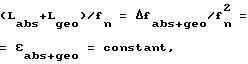
Из уравнений (7) и (8) легко можно определить отношение акустических импедансов z и искомое значение плотности:
Для повышения точности и достоверности результатов вычислений эффективное значение собственной частоты преобразователя следует рассчитать по значениям соответствующих пар резонансов жидкости по обе стороны от собственной частоты преобразователя. Точно так же и эффективное значение акустического импеданса преобразователей следует определять по резонансам эталонной камеры, заполненной водой. При этом можно использовать метод усреднения значений нескольких резонансов жидкости или значений соответствующих пар резонансов по обе стороны от собственной частоты преобразователя.From equations (7) and (8), one can easily determine the ratio of acoustic impedances z and the desired density value:
To increase the accuracy and reliability of the calculation results, the effective value of the natural frequency of the converter should be calculated from the values of the corresponding pairs of resonances of the liquid on both sides of the natural frequency of the converter. Similarly, the effective value of the acoustic impedance of the transducers should be determined by the resonances of the reference chamber filled with water. In this case, one can use the method of averaging the values of several resonances of a liquid or the values of the corresponding pairs of resonances on both sides of the natural frequency of the converter.
На фиг. 3 частично в разрезе показана блок-схема основных компонентов ультразвуковой измерительной системы, предназначенной для измерения данных P-V-T пробы жидкости. Эта система содержит акустические, резонансные камеры 100, помещенные в сосуд 102, который заполнен жидкостью 123 под давлением. Давление в жидкости 123 создается плунжерным насосом 104 высокого давления с приводом, например, от электродвигателя, для управления которым используется электронный блок 111 регулирования. Подобный насос описан в находящейся на рассмотрении PCT/EP93/01840. In FIG. Figure 3 partially shows a block diagram of the main components of an ultrasonic measuring system for measuring P-V-T fluid samples. This system comprises
Перемещение плунжера насоса относительно цилиндра насоса контролируется датчиком 106 перемещений. Давление внутри цилиндра насоса контролируется датчиком 105 силы. Выходные сигналы датчиков 105, 106 поступают на блок 111 регулирования. Принципиально система содержит также схему 109 автоматического контроля, которая измеряет электрические характеристики акустических резонаторов, как более подробно описано ниже. Некоторые из этих акустических резонаторов представляют собой жидкостные резонансные камеры, объединенные в камеру 100. Температура камеры 100 точно регулируется термостатом 124, внутри которого расположен сосуд под давлением. Управление термостатом осуществляется с помощью блока 122 регулирования. Для измерений данных P-V-T с высокой точностью необходимо учитывать увеличение объема системы, в которой создается избыточное давление. Для этого используется датчик напряжений или акустический преобразователь 113, установленный на сосуде под давлением. Соединив преобразователь со схемой 109, можно использовать его в качестве акустического резонатора. The movement of the pump plunger relative to the pump cylinder is controlled by the
Управление всеми указанными выше элементами системы осуществляется от блока 112 памяти и регулирования. Management of all the above system elements is carried out from the
Показанная в качестве предпочтительного варианта изобретения на фиг. 4 система включает в себя несколько акустических резонансных камер 100, в каждой из которых имеются электроакустический излучающий преобразователь 3, полость 2 и электроакустический принимающий преобразователь 4. Резонансные камеры соединены, как показано, между селекторными переключателями 5, которые имеют управляющий вход 5c, на который подается управляющий сигнал, по которому соответствующая резонансная камера включается в цепь соответственно между входом 5a и выходом 5b. Управляемый напряжением генератор 1 имеет выход, соединенный с входом 5a, и управляющий вход. Частота генератора 1 регулируется соединенной с его управляющим входом электронной цепью обратной связи и при этом выходной сигнал, вырабатываемый принимающим преобразователем 4 выбранной камеры, имеет строго заданное смещение по фазе относительно напряжения возбуждения, подаваемого от генератора 1 на излучающий преобразователь 3 этой камеры. Цепь обратной связи является частью схемы фазовой синхронизации, которая синхронизирует генератор 1 на частоту, определяемую собственной частотой резонансной камеры и сдвигом фазы между сигналом возбуждения и выходным сигналом выбранной акустической камеры 100. Этот сдвиг фаз можно задать с помощью отдельного внешнего устройства, как более подробно описано ниже. Сигнал на выходе генератора используется также как опорный фазовый сигнал для схемы 7 генерирования импульсов, которая работает как фазовый компаратор. Для инверсии опорного фазового сигнала можно использовать отдельную схему регулирования. Shown as a preferred embodiment of the invention in FIG. 4, the system includes several
Схема фазовой синхронизации СФС, включающая цепь обратной связи, содержит следующие элементы. The SPS phase synchronization circuit including a feedback circuit contains the following elements.
а) Управляемый напряжением генератор 1, который выполнен по типу генератора, выходная частота которого является монотонной функцией от подаваемого на его вход входного управляющего напряжения. Амплитуда выходного напряжения УНГ не должна зависеть от его частоты. a) A voltage-controlled
б) Двухсекционный селекторный переключатель 5 с входной и выходной секциями, каждая из которых работает как однополюсный выключатель на несколько положений, который включает в схему СФС выбранную камеру 100. b) Two-
в) Ограничивающий усилитель 6, который принимает сигнал с выхода выбранной камеры 100 и преобразует его в квадратную волну, имеющую знак или полярность принимаемого сигнала с сохранением его фазы. c) The limiting
г) Фазовый компаратор 7, который представляет собой высокоимпедансный источник тока, создающий однонаправленные импульсы постоянной амплитуды, длительность которых пропорциональна разнице фаз между выходным сигналом задающего генератора 1 и выходным сигналом усилителя 6. d)
д) Суммирующая схема 14a, на первый вход которой поступает выходной сигнал фазового компаратора 7, а на второй поступает выходной сигнал цифроаналогового (Ц/А) преобразователя 8 и которая вырабатывает первое регулируемое напряжение, которое используется как напряжение регулирования фазы. На преобразователь 8 от схемы управления 9, в качестве которой можно использовать персональный компьютер (ПК) или другое устройство управления, поступает цифровой сигнал регулирования фазы. d) A summing
е) Схема 10 интегрирования, вход которой соединен с выходом суммирующей схемы 14a, а выходное напряжение пропорционально временному интегралу суммы вырабатываемых фазовым компаратором 7 импульсов тока, характеризующих фазовый сдвиг, и смещенного по фазе на 180o тока, пропорционального регулируемому напряжению регулирования фазы. Схема 10 интегрирования управляется внешним выключателем 11, который имеет управляющий вход 11a и который при возбуждении восстанавливает до исходного состояния уровень выходного напряжения интегратора, например, заземляя его. При этом цепь обратной связи между фазовым детектором 7 и УНГ 1 разрывается, и схема СФС перестает работать.f)
з) Вторая суммирующая схема 14b, первый вход которой соединен с выходом интегрирующей схемы 10, а второй соединен еще с одним цифроаналоговым преобразователем 12 и которая вырабатывает второе регулируемое напряжение (напряжение регулирования частоты). На преобразователь 12 от схемы управления, в качестве которой можно использовать ПК или другое устройство управления, поступает цифровой сигнал регулирования частоты. Выход схемы 14b суммирования соединен с управляющим входом УНГ и замыкает тем самым всю схему фазовой синхронизации. h) The second summing
В показанной на фиг. 4 схеме имеется схема измерения частоты выходного сигнала генератора и амплитуды сигнала на выходе из камеры. In the embodiment shown in FIG. 4 diagram there is a circuit for measuring the frequency of the output signal of the generator and the amplitude of the signal at the output of the camera.
Схема измерения частоты генератора содержит таймер с кварцевым генератором 15, вырабатывающим тактовые импульсы, счетчик 16 с предварительной установкой, задающий временной интервал считывания тактового импульса, начиная от заданного числа до нуля, и триггерную схему 17, синхронизирующую внешний запускающий сигнал, подаваемый на вход 17a, с тактовыми импульсами таким образом, что начало и окончание временного интервала, определяемого таймером, совпадает с тактовыми импульсами. Таймер контролирует период считывания счетчика 18, на который поступает выходной сигнал УНГ 1. The oscillator frequency measuring circuit includes a timer with a
Схема генерирования сигнала, характеризующего амплитуду сигнала на выходе камеры 100, содержит умножитель 19, в котором поступающий на него с выхода 5b сигнал умножается на свою собственную величину, т.е. на соответствующий сигнал такой же полярности, вырабатываемый ограничивающим усилителем 6, и полученный сигнал усредняется в схеме усреднения, на управляющий вход 21a которой поступает постоянный по времени сигнал управления, а затем обрабатывается в блоке 20, который представляет собой аналого-цифровой преобразователь, выход 20a которого соединен с цифровым дисплеем или ПК. The signal generating circuit characterizing the amplitude of the signal at the output of the
Как указано выше, переключатель 11 вместе с интегратором 10 образуют устройство, разрывающее с помощью внешнего устройства управления цепь обратной связи при отсоединении интегратора 10 от сумматора 14b, при этом система будет работать как обычный анализатор, в котором частота генератора регулируется только выходным сигналом схемы 12. В этом случае интегрирующая схема 10 работает как усилитель с низкочастотным пропусканием, единственный вход которого соединен с фазовым детектором 7 и который на выходе вырабатывает сигнал, характеризующий фазу сигнала на выходе из резонансной камеры. Именно этот сигнал, а не сигнал на выходе из схемы 19, можно подать на А/Ц-преобразователь блока 20, пропустив его через имеющий внешнее управление аналоговый умножитель 21. Для работы системы в таком режиме в элементах 10, 8 и 20 необходимо предусмотреть соответствующие коммутаторы каналов. As indicated above, the
Первым режимом работы, показанной на фиг. 4 схемы, является режим анализатора. В этом режиме частота УНГ 1 ступенчато повышается в заданном диапазоне частот путем ступенчатого изменения входного напряжения, вырабатываемого регулирующим частоту Ц/А-преобразователем блока 13. На каждой ступени частота измеряется с помощью счетчика 18 считыванием в течение периода времени, заданного таймером 15, 16 и 17, количества вырабатываемых генератором 1 колебаний его выходного сигнала. Время считывания определяется величиной управляющего напряжения, подаваемого на вход 17a. Период считывания должен обеспечить необходимую точность измерений, и на практике он составляет обычно от 10 до 100 миллисекунд для мегагерцевого диапазона частот УНГ. Кроме того, временной интервал должен быть достаточно длинным, с тем чтобы в течение этого времени можно было успеть провести несколько измерений амплитуды и фазы сигнала, снимаемого на этой частоте с выбранной резонансной камеры 100. Для повышения точности результаты этих измерений можно усреднить. В результате в определенном частотном диапазоне получают фазочастотную и амплитудно-частотную характеристики выбранной камеры с несколькими резонансными частотами. Полученная информация используется для определения регулирующего частоту напряжения Ц/А-преобразователя блока 13 при выборе в этом диапазоне частот требуемого резонанса. The first mode of operation shown in FIG. 4 circuit, is the analyzer mode. In this mode, the frequency of the
Второй режим работы, который начинается обычно после настройки регулирующего частоту Ц/А-преобразователя на конкретный выбранный резонанс, и настройки регулирующего фазу Ц/А-преобразователя блока 9 на определенное значение, лежащее в пределах диапазона синхронизации фазового компаратора 7, представляет собой работу в режиме ШПЧПМ, в который система переходит после замыкания цепи обратной связи, т.е. после возбуждения интегратора 10 путем подачи на его вход 11a сигнала соответствующего уровня. При работе в этом режиме ступенчато изменяется входное напряжение регулирующего фазу Ц/А- преобразователя. Для каждой ступени определяется частота генератора 1. В течение каждого интервала считывания частоты проводятся многократные измерения амплитуды и других параметров, например, температуры и давления пробы, которые регистрируются и усредняются. The second mode of operation, which usually begins after tuning the frequency / frequency converter of the D / A converter to a specific selected resonance, and setting the phase / voltage converter of the D / A converter of block 9 to a certain value that lies within the synchronization range of the
Систему можно переключить на другую резонансную частоту выбранной камеры временным замыканием управляемого от внешнего устройства выключателя 11 на непродолжительное время (с размыканием цепи обратной связи) и изменением на это время задающего частоту напряжения. Длительность такого отключения должна быть достаточно большой с тем, чтобы УНГ стабилизировался на новую частоту. Изменение регулирующего частоту напряжения при открытом выключателе 11 и работающем в цепи обратной связи интеграторе 10 не изменяет рабочей частоты УНГ, поскольку обратная связь компенсирует любые изменения напряжения на выходе схемы 12 путем соответствующего изменения в противофазе выходного напряжения интегратора 10. The system can be switched to another resonant frequency of the selected camera by temporarily shorting the
Система, показанная на фиг. 5, представляет собой предпочтительный вариант выполнения изобретения и содержит описанную выше и показанную на фиг. 4 схему. При этом одни и те же элементы, показанные на фиг. 4 и 5, имеют одинаковые обозначения. The system shown in FIG. 5 is a preferred embodiment of the invention and comprises the above and shown in FIG. 4 circuit. Moreover, the same elements shown in FIG. 4 and 5 have the same designation.
Система, показанная на фиг. 5, содержит аналогичную рассмотренной выше и показанной на фиг. 4 схему фазовой синхронизации СФС. Основными дополнительными элементами системы, показанной на фиг. 5, являются арифметико-логическое устройство АЛУ 50, вычислительное устройство 52 и управляющий блок 54, в качестве которого можно использовать микропроцессор. The system shown in FIG. 5 contains the same as described above and shown in FIG. 4 scheme of phase synchronization SPS. The main additional elements of the system shown in FIG. 5 are the arithmetic
В показанной на фиг. 5 системе имеется также регистр 56 для хранения информации о значениях частоты и амплитуды, которая обрабатывается в вычислительном устройстве 52, и модулятор 58, который модулирует аналоговое регулирующее фазу напряжение, вырабатываемое Ц/А-преобразователем 8, синусоидальным модулирующим сигналом. Схема модуляции включает источник 60 модулирующего напряжения, вырабатывающий синусоидальный модулирующий сигнал, частота которого меньше частоты ультразвуковых волн; модулирующий переключатель 62, который включает и выключает генератор 60 модулирующего сигнала; и модулятор 64, на который подается регулирующее фазу напряжение от Ц/А-преобразователя 8 и выходной сигнал генератора 60 и который подает на вход в сумматор 14a модулированный сигнал регулирования фазы. In the embodiment shown in FIG. 5, the system also has a
Модулирующий сигнал подается также на первый вход умножителя 66, на второй вход которого с выхода усредняющей схемы 21 подается сигнал, характеризующий амплитуду. The modulating signal is also fed to the first input of the
Выход умножителя 66 соединен через низкочастотный фильтр 70 со схемой, генерирующей сигнал ошибки или отклонения. Этот сигнал подается на соответствующий вход управляющего блока 54. Сигнал отклонения равен нулю, когда отфильтрованный выходной сигнал умножителя 66 лежит в заранее заданном интервале между положительной и отрицательной пороговыми величинами, которые равны друг другу и близки к нулю, или же он равен некоторой положительной величине (разности), когда выходной сигнал превышает положительный пороговый уровень, или некоторой отрицательной величине (разности), когда выходной сигнал становится меньше отрицательного порогового уровня. Первый буферный регистр 72 соединен с регулирующим частоту выходом управляющего блока 54 и входом Ц/А-преобразователя 12. Второй буферный регистр 74 соединен с регулирующим фазу выходом управляющего блока 54 и соответствующим входом АЛУ 50, а третий буферный регистр 76 соединен с выходом АЛУ и входом Ц/А-преобразователя 8. Выход регистра 76 соединен обратной связью со входом АЛУ. The output of the
При определении плотности или других P-V-Т-параметров жидкости с помощью показанной на фиг. 5 системы одна из камер 100 заполняется пробой исследуемой жидкости, а другая камера заполняется эталонной жидкостью, например, водой. Остальные камеры можно заполнить другими исследуемыми жидкостями. Предполагается, что все камеры 100 показанной на фиг. 5 системы имеют одинаковые характеристики. When determining the density or other P-V-T parameters of a liquid using the one shown in FIG. 5 of the system, one of the
Вначале определяется, как указано выше, предельная частота flim камеры 100, после чего в регистре частоты (не показан) управляющего блока 54 задается (существенно выше частоты flim) диапазон частот, внутри которого будут производиться ультразвуковые измерения.First, the limiting frequency f lim of the camera 100 is determined, as indicated above, and then in the frequency register (not shown) of the control unit 54 a frequency range is set (substantially higher than the frequency f lim ) within which ultrasonic measurements will be made.
Цикл измерений начинается с того, что управляющий блок 54 после подачи соответствующего сигнала управления на вход 5c включает в систему эталонную камеру. СФС при подаче соответствующего сигнала на вход 11a начинает работать в режиме анализатора. При подаче соответствующего сигнала регулирования частоты к Ц/А- преобразователю 12 частота УНГ 1 (фиг. 4) проходит через весь заданный заранее диапазон частот, превышающих flim. Изменение частоты происходит при ступенчатом бесконечно малом увеличении буферного цифрового сигнала, поступающего на вход в Ц/А- преобразователь 12. Резонансы ультразвуковых волн, которые имеют место в эталонной камере при изменении частоты в заданном диапазоне, определяются описанным выше способом и информация о них хранится в регистре 56.The measurement cycle begins with the fact that the
После этого система переключается на работу в режиме СФС, для этого замыкается цепь обратной связи СФС и путем подачи на вход Ц/А- преобразователя 12 соответствующего сигнала генератор настраивается на первую собственную частоту жидкости. При работе в этом режиме механизмом цифровой обратной связи определяется максимальная амплитуда резонансного пика. Регулирующее фазу напряжение на входе 14a СФС модулируется синусоидальным сигналом модулятора 60 с частотой модуляции ω. Тогда сигнал на выходе из резонансной камеры будет иметь вид
Uout = a sin ωt+b sin 2ωt.
После перемножения Uout с модулирующим сигналом в умножителе 66 получается сигнал, содержащий постоянную составляющую и переменную составляющую с частотой 2ω. После фильтрации и отделения переменной составляющей постоянная составляющая анализируется детектором 68 нулевого напряжения. В том случае, когда абсолютное значение постоянной составляющей будет меньше заранее заданного близкого к нулю порогового значения, цифровой сигнал на выходе детектора 68 будет равен нулю. Если положительная постоянная составляющая сигнала превысит пороговое значение, то на выходе детектора 68 появится положительный разностный сигнал, а при превышении отрицательной постоянной составляющей сигнала порогового значения на выходе детектора 68 появится отрицательный разностный сигнал.After that, the system switches to operation in the SPS mode, for this, the SPS feedback circuit is closed and by supplying the corresponding signal to the input of the D /
U out = a sin ωt + b sin 2ωt.
After multiplying U out with a modulating signal in
При таком режиме работы АЛУ блок 50, который имеет буферные вход и выход, сдвигает цифровой обратной связью фазовое число на фазовое число резонансного максимума и поддерживает его на этом уровне, обеспечивая возможность точного считывания частоты и измерения амплитуды на резонансном максимуме. With this mode of operation, the
Информация о максимальной амплитуде, фазе и частоте на максимуме хранится в регистре 56 вычислительного устройства. Information about the maximum amplitude, phase and frequency at the maximum is stored in the
При работе системы в режиме СФС боковые частоты f' и f'' при заданных уровнях амплитуды или фазы, расположенные слева и справа от резонансного максимума, измеряются при изменении значений фазы сигналов, поступающих к фазовому Ц/А- преобразователю 8 от АЛУ 50 через регистр 76. Таким способом получают данные о последующих резонансных пиках, которые поступают в регистр 56. When the system is operating in the SPS mode, the lateral frequencies f 'and f' 'at specified amplitude or phase levels located to the left and right of the resonance maximum are measured when the phase values of the signals arriving at the phase D /
После этого переключателем 5 в систему измерений включается соответствующая камера с пробой и описанная выше процедура последовательно повторяется для всех камер. After that, with the
Под управлением блока 54 вычислительный блок 52 по алгоритму, показанному на фиг. 6, рассчитывает акустический импеданс Z и соответственно плотность ρ исследуемой жидкости Δfπ и fπ представляют собой соответственно ШПЧПМ и собственную частоту вблизи нечетных кратностей f0/2.Under the control of
На фиг. 7 схематично показан еще один вариант выполнения изобретения. Сосуд 102 под давлением герметично закрыт крышкой 132, имеющей, например, не пропускающую жидкость резьбу, и заполнен жидкостью 123, давление в которой создается насосом 104. В сосуде расположены по крайней мере две акустические резонансные камеры 100a и 100b, одна из которых используется в качестве эталонной для получения базовых характеристик, а другая (ие) заполняется (ются) пробой (ами) жидкости, исследуемой сравнительным относительно эталона методом. Внутри сосуда 102 установлен полупроводниковый чувствительный к давлению резонатор 108, позволяющий быстро определить начальные условия эксперимента в жидкости 123. Этот резонатор можно использовать для быстрой и более грубой предварительной настройки системы на требуемое резонансное состояние с последующим проведением более точных измерений при переключении системы на резонансную камеру 100. При необходимости внутрь сосуда 102 можно, разумеется, поместить более двух резонансных камер в том случае, если сосуд 102 имеет достаточно большой для этого объем. При использовании одной из резонансных камер в качестве эталонной остальные камеры можно использовать для соответствующих измерений. При необходимости проведения измерений во всех камерах, когда точность измерений не должна быть очень высокой, можно при проведении сравнительных резонансных измерений использовать резонатор 108. In FIG. 7 schematically shows another embodiment of the invention. The
Выходные сигналы от всех помещенных внутрь сосуда 102 камер выводятся с применением соответствующих уплотнений через крышку 132 и поступают в схему 109, которая преобразует поступающие в нее сигналы в сигналы другой формы, которые подаются в предназначенную для их запоминания и обработки схему 112. Схема 112 генерирует команды, необходимые для управления схемой 111 управления насоса, которая в свою очередь обеспечивает прецизионное регулирование насоса 104. The output signals from all chambers placed inside the
Еще один вариант изобретения показан на фиг. 8. В этом варианте используется акустический преобразователь 113, который установлен на сосуде 102 и предназначен для измерения акустических резонансных частот сосуда при различных условиях. Изменения формы или геометрии сосуда, связанные с изменениями создаваемого в нем давления, сопровождаются изменениями собственной частоты сосуда, и определенная один раз зависимость собственной частоты сосуда от его формы позволяет точно контролировать механические эффекты, которые могут отрицательно сказаться на точности проводимых измерений. Another embodiment of the invention is shown in FIG. 8. In this embodiment, an
Используя эти зависимости, можно создавать внутри сосуда требуемое давление путем подачи выходного сигнала преобразователя 113 в схему управления насоса 104. Выходной импеданс преобразователя 113 зависит от испытываемых им механических вибраций. Соединив преобразователь 113 с импедансным мостом 114, можно полностью компенсировать изменения импеданса преобразователя, обусловленные изменениями собственной частоты сосуда 102. Сигнал на выходе их моста 114, характеризующий фактический импеданс преобразователя 113, подается в схему 109, в которой он преобразуется в сигналы, которые можно использовать в схеме 112 запоминания и обработки и в схеме 111 управления насоса. Последующее регулирование насоса 104 сопровождается изменением давления внутри сосуда 102 до заданной величины. При этом по сравнению с вариантом использования резонатора 108 по фиг. 7 необходимое давление внутри сосуда 102 создается быстрее и с большей точностью. Using these dependences, it is possible to create the required pressure inside the vessel by supplying the output signal of the
Вариант, показанный на фиг. 8, обладает тем преимуществом, что он позволяет контролировать процесс старения сосуда путем контроля изменений его собственной частоты при отсутствии в нем давления. В течение всего срока службы сосуда его собственная частота изменяется, и степень такого изменения в промежутках между измерениями позволяет судить о степени старения сосуда и принимать решения о возможности или невозможности его дальнейшего использования для проведения высокоточных измерений. The embodiment shown in FIG. 8, has the advantage that it allows you to control the aging process of the vessel by controlling changes in its natural frequency in the absence of pressure in it. Over the entire life of the vessel, its natural frequency changes, and the degree of such a change in the intervals between measurements allows us to judge the degree of aging of the vessel and make decisions about the possibility or impossibility of its further use for high-precision measurements.
В показанном на фиг. 9 варианте выполнения изобретения предусмотрена возможность очень точного контроля температуры путем использования нескольких датчиков 17, 18 и 19 температуры с высокой разрешающей способностью, которые установлены в различных местах камеры 100, сосуда 102 под давлением и термостата 124. Выходные сигналы от этих датчиков поступают на блок 120, который преобразует их в соответствующие электрические сигналы, используемые в качестве сигналов, подаваемых в схему 121 обработки, в которой имеются высоко стабильные и точные дифференциальные усилители. As shown in FIG. In an embodiment of the invention, a very precise temperature control is possible by using several high-
Отклонения от эталонных сигналов, поступающих из схемы 112 запоминания и контроля, используются для выработки сигналов регулирования, поступающих в схему 122 регулирования, которая в свою очередь вырабатывает управляющие сигналы, по которым осуществляется управление соответствующими нагревательными или охлаждающими устройствами термостата 124. Применение группы установленных в различных местах датчиков температуры позволяет на ранней стадии зафиксировать изменения температуры и с помощью системы регулирования с высокой точностью поддерживать на заданном уровне температурные условия эксперимента. Deviations from the reference signals coming from the memory and
Предпочтительным диапазоном частот ультразвуковых волн является диапазон от примерно 105 Гц до нескольких 107 Гц.A preferred frequency range for ultrasonic waves is from about 10 5 Hz to several 10 7 Hz.
Примеры определения плотностей
4-х канальная резонансная камера:
преобразователи из ниобата лития.Density Examples
4-channel resonant camera:
converters from lithium niobate.
r0 = 2,5 мм, d = 7,0 мм, fp = 10,0 МГц
Измерения на эталонной камере, заполненной водой
t = 25,0 [oC]
ρ = 997 [кг/м2с]
c = 1497 [м/с]; V.A. DelGrosso and C.M. Mader, J. Acoust. Soc. Amer. 52 (1972) 1442-1446.r 0 = 2.5 mm, d = 7.0 mm, f p = 10.0 MHz
Measurements on a reference chamber filled with water
t = 25.0 [ o C]
ρ = 997 [kg / m 2 s]
c = 1497 [m / s]; VA DelGrosso and CM Mader, J. Acoust. Soc. Amer. 52 (1972) 1442-1446.
(aw/f2) = 22•10-15 [с2/м]; T. Funck und F. Eggers, Fortschritte der Akustik - DAGA'85 (1985) 651-654.(a w / f 2 ) = 22 • 10 -15 [s 2 / m]; T. Funck und F. Eggers, Fortschritte der Akustik - DAGA'85 (1985) 651-654.
(Первый этап: расчет flim для эталонной камеры:
flim = [c/r02(aw/f2)]1/3 = [1497/(2,5•10-3)2•22•10-15]1/3 = 22,16 [МГц]
Второй этап: измерение при fn = nfπ
расчет εabs+geo:
fn = 25,110 [МГц]
Δfn = Δfabs+geo = 6776 [Гц]
εabs+geo 10,747•10-12 [с]
Третий этап: измерение Δfn при fn=28,934 [МГц]
Δfn = 11125 [Гц]; f0 = 9,999 [МГц]
Δfabs+geo = 10,747•10-12 [с]•(28,934•106 [Гц])2 = 8997 [Гц]
Δfrefl = Δfn-Δfabs+geo = 11125 - 8997 = 2128 [Гц]
-ln(cosθ) = Δfrefl•π•7,0•10-3 [м]/1497 [м/с] = 0,031261
-ln(cosθ) = 0,031261--->z/tg π fn/f0) = 0,1249
tg(πfn/f0) = tg(π • 28,934/9,999) = -0,34698
z = 0,1249•0,34699 = 0,04334
Z0 = ρ•c/z = 997•1497/0,04334 = 34,437•106 [кг/м2с]
Измерение на камере 1 для пробы, заполненной 0,100M NaCl
Δfn при fn = 29,057 [МГц]:
fn = 29,057 [МГц]; Δfn = 11897 [Гц]; f0 = 9,999 [МГц]
Δfabs+geo = 10,747•10-12 [с]•(29,057•106 [Гц])2 = 9074 [Гц]
Δfrefl = Δfn-Δfabs+geo = 11897 - 9074 = 2823 [Гц]
-ln(cosθ) = Δfrefl•π• 7,0•10-3 [м]/1503,4 [м/с] = 0,04129
-ln(cosθ) = 0,04129--->z/tg π fn/f0) = 0,1436
tg(πfn/f0) = tg(π • 29,057/9,999) = -0,30424
z = 0,1436•0,30424 = 0,043700
ρ = Z0•z/c = 34,437•106•0,043700/1503,4 = 1001 [кг/м3]
ρ, измеренная денситометром, составила 1001 [кг/м3]
Измерение на камере 2 для пробы, заполненной 0,050М NaCl
Δfn при fn = 28,996 [МГц]:
fn = 28,996 [МГц]; Δfn = 11481 [Гц]; f0 = 9,999 [МГц]
Δfabs+geo = 10,747•10-12 [с]•(28,996•106 [Гц])2 = 9036 [Гц]
Δfrefl = Δfn-Δfabs+geo = 11481 - 9036 = 2445 [Гц]
-ln(cosθ) = Δfrefl•π •7,0•10-3 [м]/1500,2 [м/с] = 0,03584
-ln(cosθ) = 0,03584 → z/tg(πfn/f0) = 0,13378
tg(πfn/f0) = tg(π •28,996/9,999) = -0,32530
z = 0,13378•0,32530 = 0,04352
ρ = Z0•z/с = 34,437•106•0,043520/1500,2 = 999 [кг/м3]
ρ, измеренная денситометром, составила 999 [кг/м3](First step: calculating f lim for the reference camera:
f lim = [c / r 02 (a w / f 2 )] 1/3 = [1497 / (2.5 • 10 -3 ) 2 • 22 • 10 -15 ] 1/3 = 22.16 [MHz]
Second stage: measurement at f n = nf π
calculation of ε abs + geo :
f n = 25.110 [MHz]
Δf n = Δf abs + geo = 6776 [Hz]
ε abs + geo 10,747 • 10 -12 [s]
Third stage: Δf n measurement at f n = 28.934 [MHz]
Δf n = 11125 [Hz]; f 0 = 9.999 [MHz]
Δf abs + geo = 10.747 • 10 -12 [s] • (28.934 • 10 6 [Hz]) 2 = 8997 [Hz]
Δf refl = Δf n -Δf abs + geo = 11125 - 8997 = 2128 [Hz]
-ln (cosθ) = Δf refl • π • 7.0 • 10 -3 [m] / 1497 [m / s] = 0.031261
-ln (cosθ) = 0.031261 ---> z / tg π f n / f 0 ) = 0.1249
tg (πf n / f 0 ) = tg (π • 28.934 / 9.999) = -0.34698
z = 0.1249 • 0.34699 = 0.04334
Z 0 = ρ • c / z = 997 • 1497 / 0.04334 = 34.437 • 10 6 [kg / m 2 s]
Measurement on
Δf n at f n = 29,057 [MHz]:
f n = 29,057 [MHz]; Δf n = 11897 [Hz]; f 0 = 9.999 [MHz]
Δf abs + geo = 10.747 • 10 -12 [s] • (29.057 • 10 6 [Hz]) 2 = 9074 [Hz]
Δf refl = Δf n -Δf abs + geo = 11897 - 9074 = 2823 [Hz]
-ln (cosθ) = Δf refl • π • 7.0 • 10 -3 [m] / 1503.4 [m / s] = 0.04129
-ln (cosθ) = 0.04129 ---> z / tg π f n / f 0 ) = 0.1436
tg (πf n / f 0 ) = tg (π • 29,057 / 9,999) = -0,30424
z = 0.1436 • 0.30424 = 0.043700
ρ = Z 0 • z / c = 34.437 • 10 6 • 0.043700 / 1503.4 = 1001 [kg / m 3 ]
ρ measured by densitometer was 1001 [kg / m 3 ]
Measurement on
Δf n at f n = 28,996 [MHz]:
f n = 28.996 [MHz]; Δf n = 11481 [Hz]; f 0 = 9.999 [MHz]
Δf abs + geo = 10.747 • 10 -12 [s] • (28.996 • 10 6 [Hz]) 2 = 9036 [Hz]
Δf refl = Δf n -Δf abs + geo = 11481 - 9036 = 2445 [Hz]
-ln (cosθ) = Δf refl • π • 7.0 • 10 -3 [m] / 1500.2 [m / s] = 0.03584
-ln (cosθ) = 0.03584 → z / tg (πf n / f 0 ) = 0.13378
tg (πf n / f 0 ) = tg (π • 28,996 / 9,999) = -0,32530
z = 0.13378 • 0.32530 = 0.04352
ρ = Z 0 • z / s = 34.437 • 10 6 • 0.043520 / 1500.2 = 999 [kg / m 3 ]
ρ measured by densitometer was 999 [kg / m 3 ]
Claims (19)
значения частоты fn, которому соответствует максимальное значение амплитуды ультразвуковых волн в заполненной пробой резонансной камере, и второго fn1 и третьего fn2 значений частоты, при которых величина амплитуды ультразвуковых волн меньше указанного максимального значения, определяют значение ширины полосы частот на уровне половинной мощности Δfn= fn1-fn2, по значению Δfn определяют значения потерь Lrefl, которые имеют место вблизи собственных частот преобразователей, связанных с неидеальными условиями отражения волн на поверхностях преобразователей, а затем определяют
-ln(cosθ) = π•d•fn•Lref1/c,
где с - скорость звука в жидкости;
d - расстояние между преобразователями,
затем, зная эту величину, определяют коэффициент J по соответствующей функции зависимости коэффициента J от значений -ln(cosθ) или с помощью числовой таблицы, после этого вычисляют отношение акустических импедансов z по формуле
z = J•tg(π•fn/fo),
где f0 - основная собственная частота преобразователей,
и искомое значение плотности определяют из соотношения
ρ = Zo•z/c,
где Z0 - акустический импеданс материала преобразователя.1. A method for determining the density of a liquid, based on the study of the resonant behavior of a liquid sample in an ultrasonic resonance chamber having an ultrasound emitting transducer and an opposite transducer receiving ultrasound transducer and in the space between them a cavity for a sample of the studied fluid, by creating variable frequency ultrasound waves in it, including filling the cavity resonance chamber reference fluid, selecting at least one resonance frequency f no ultrasonic waves of a plurality of such ezonansnyh frequency in a predetermined frequency range above the threshold frequency f lim resonant chamber, above which the effects of diffraction of ultrasonic waves in the chamber can be neglected, filling the cavity resonance chamber test liquid sample, creating ultrasonic waves from the selected resonant frequency f no in this trial feeding ultrasonic frequency signal to a radiating converter, characterized in that the phase shift θ is changed between the supplied signal and the output signal removed from the receiving converter, for definitions of the first
the frequency value f n , which corresponds to the maximum value of the amplitude of the ultrasonic waves in the filled resonance chamber, and the second f n1 and third f n2 frequency values at which the magnitude of the amplitude of the ultrasonic waves is less than the specified maximum value, determine the frequency bandwidth at half power Δf n = f n1 -f n2, by the value Δf n determined loss value L refl, which occur near the natural frequencies of the transducers associated with the non-ideal reflection conditions on the wave surfaces reobrazovateley then determined
-ln (cosθ) = π • d • f n • L ref1 / c,
where c is the speed of sound in a liquid;
d is the distance between the transducers,
then, knowing this value, determine the coefficient J by the corresponding function of the dependence of the coefficient J on the values -ln (cosθ) or using a numerical table, after which the ratio of acoustic impedances z is calculated by the formula
z = J • tg (π • f n / f o ),
where f 0 is the fundamental natural frequency of the converters,
and the desired density value is determined from the relation
ρ = Z o • z / c,
where Z 0 is the acoustic impedance of the transducer material.
Applications Claiming Priority (3)
| Application Number | Priority Date | Filing Date | Title |
|---|---|---|---|
| EP93117619.2 | 1993-10-29 | ||
| EP93117619 | 1993-10-29 | ||
| PCT/EP1994/003548 WO1995012123A1 (en) | 1993-10-29 | 1994-10-28 | Method and system for measuring fluid parameters by ultrasonic methods |
Publications (2)
| Publication Number | Publication Date |
|---|---|
| RU96110897A RU96110897A (en) | 1998-08-10 |
| RU2144183C1 true RU2144183C1 (en) | 2000-01-10 |
Family
ID=8213385
Family Applications (1)
| Application Number | Title | Priority Date | Filing Date |
|---|---|---|---|
| RU96110897A RU2144183C1 (en) | 1993-10-29 | 1994-10-28 | Method and system determining density of liquid |
Country Status (10)
| Country | Link |
|---|---|
| US (1) | US5804698A (en) |
| EP (1) | EP0725932B1 (en) |
| JP (1) | JP3571345B2 (en) |
| KR (1) | KR960706072A (en) |
| AT (1) | ATE182214T1 (en) |
| AU (1) | AU7992894A (en) |
| CA (1) | CA2175232A1 (en) |
| DE (1) | DE69419518T2 (en) |
| RU (1) | RU2144183C1 (en) |
| WO (1) | WO1995012123A1 (en) |
Cited By (1)
| Publication number | Priority date | Publication date | Assignee | Title |
|---|---|---|---|---|
| RU2210764C1 (en) * | 2002-01-03 | 2003-08-20 | Самарский государственный аэрокосмический университет им. акад. С.П. Королева | Procedure determining density of liquids and device for its implementation |
Families Citing this family (30)
| Publication number | Priority date | Publication date | Assignee | Title |
|---|---|---|---|---|
| GB9815232D0 (en) * | 1998-07-15 | 1998-09-09 | Hydramotion Ltd | Diagnostic sensor |
| US6477898B1 (en) * | 2000-07-06 | 2002-11-12 | Motorola, Inc. | Membrane mask stress measurement apparatus and method therefor |
| EP1311822A4 (en) * | 2000-07-10 | 2008-12-03 | Nanoalert Israel Ltd | Method and apparatus for determining the composition of fluids |
| DE10036565C2 (en) * | 2000-07-27 | 2002-07-25 | Sonem Gmbh | Device for determining the change in density of a medium |
| US20040119793A1 (en) * | 2000-09-25 | 2004-06-24 | Mutz Mitchell W. | Acoustic assessment of fluids in a plurality of reservoirs |
| US7900505B2 (en) * | 2000-09-25 | 2011-03-08 | Labcyte Inc. | Acoustic assessment of fluids in a plurality of reservoirs |
| US6809249B2 (en) * | 2001-01-12 | 2004-10-26 | Protune Corp. | Self-aligning ultrasonic displacement sensor system, apparatus and method for detecting surface vibrations |
| RU2232384C2 (en) * | 2001-01-23 | 2004-07-10 | Яхно Татьяна Анатольевна | Method of investigation of multicomponent liquid |
| US20030101819A1 (en) * | 2001-12-04 | 2003-06-05 | Mutz Mitchell W. | Acoustic assessment of fluids in a plurality of reservoirs |
| US7717544B2 (en) * | 2004-10-01 | 2010-05-18 | Labcyte Inc. | Method for acoustically ejecting a droplet of fluid from a reservoir by an acoustic fluid ejection apparatus |
| US7454958B2 (en) * | 2001-12-04 | 2008-11-25 | Labcyte Inc. | Acoustic determination of properties of reservoirs and of fluids contained therein |
| US7354141B2 (en) | 2001-12-04 | 2008-04-08 | Labcyte Inc. | Acoustic assessment of characteristics of a fluid relevant to acoustic ejection |
| EP1319947A1 (en) * | 2001-12-14 | 2003-06-18 | Ultrasonic Scientific Limited | Acoustical Cell for Material Analysis |
| US20060196271A1 (en) * | 2002-10-28 | 2006-09-07 | Bela Jancsik | Acoustic array analytical system |
| EP1455184A1 (en) * | 2003-03-07 | 2004-09-08 | Ultrasonic Scientific Limited | Ultrasonic analyser |
| DE10326078A1 (en) * | 2003-06-10 | 2005-01-05 | Fraunhofer-Gesellschaft zur Förderung der angewandten Forschung e.V. | Method for measuring the acoustic impedance of a fluid |
| US20050205301A1 (en) * | 2004-03-19 | 2005-09-22 | Halliburton Energy Services, Inc. | Testing of bottomhole samplers using acoustics |
| US7753636B2 (en) * | 2008-03-25 | 2010-07-13 | Hennig Emmett D | Adjustable bale mover spikes |
| JP5277214B2 (en) * | 2010-07-27 | 2013-08-28 | 株式会社日立ハイテクノロジーズ | Automatic analyzer |
| ES2967784T3 (en) | 2011-02-15 | 2024-05-03 | Hemosonics Llc | Characterization of blood hemostasis and oxygen transport parameters |
| GB201120887D0 (en) * | 2011-12-06 | 2012-01-18 | The Technology Partnership Plc | Acoustic sensor |
| CN102901689B (en) * | 2012-10-22 | 2014-07-02 | 中国计量学院 | Seaport water density measuring instrument |
| RU2548692C1 (en) * | 2013-10-30 | 2015-04-20 | Акционерное общество "Всероссийский научно-исследовательский институт по эксплуатации атомных электростанций" (АО ВНИИАЭС) | Method of increasing reliability of ultrasonic nondestructive flaw-detective control |
| WO2016109447A1 (en) | 2014-12-29 | 2016-07-07 | Concentric Meter Corporation | Fluid parameter sensor and meter |
| US10126266B2 (en) | 2014-12-29 | 2018-11-13 | Concentric Meter Corporation | Fluid parameter sensor and meter |
| US10107784B2 (en) | 2014-12-29 | 2018-10-23 | Concentric Meter Corporation | Electromagnetic transducer |
| US9726647B2 (en) | 2015-03-17 | 2017-08-08 | Hemosonics, Llc | Determining mechanical properties via ultrasound-induced resonance |
| RU2722870C1 (en) * | 2019-10-24 | 2020-06-04 | Государственное бюджетное учреждение здравоохранения Московской области "Московский областной научно-исследовательский клинический институт им. М.Ф. Владимирского" (ГБУЗ МО МОНИКИ им. М.Ф. Владимирского) | Ultrasonic spectrometer |
| CN115307724B (en) * | 2022-08-15 | 2025-07-04 | 重庆医科大学 | A method for automatically measuring sound field |
| CN120768163B (en) * | 2025-09-05 | 2025-11-07 | 上海保兴生物设备工程有限公司 | Multi-motor pulse speed control method and system |
Citations (6)
| Publication number | Priority date | Publication date | Assignee | Title |
|---|---|---|---|---|
| US3828607A (en) * | 1973-01-24 | 1974-08-13 | Du Pont | Phase lock detection and control for piezoelectric fluid analyzers |
| US3831433A (en) * | 1971-12-07 | 1974-08-27 | Merestechnikai Kozponti | Apparatus for measuring the density of a fluid by resonance |
| GB2236591A (en) * | 1989-10-05 | 1991-04-10 | Marconi Gec Ltd | Vibrating element apparatus for fluid density and/or viscosity determination |
| EP0430859A1 (en) * | 1989-11-30 | 1991-06-05 | Puritan-Bennett Corporation | Ultrasonic gas measuring device |
| EP0502197A1 (en) * | 1990-08-24 | 1992-09-09 | Vsesojuzny Nauchno-Issledovatelsky Institut Prirodnykh Gazov (Vniigaz) | Method and device for determining physical state parameters of a medium |
| WO1993008466A1 (en) * | 1991-10-23 | 1993-04-29 | Niagara Mohawk Power Corporation | Multiple gas property sensor |
Family Cites Families (1)
| Publication number | Priority date | Publication date | Assignee | Title |
|---|---|---|---|---|
| SU684437A2 (en) * | 1977-07-12 | 1979-09-05 | Каунасский Политехнический Институт Им.Антанаса Снечкуса | Ultrasonic digital interferometer |
-
1994
- 1994-10-28 AT AT94930997T patent/ATE182214T1/en not_active IP Right Cessation
- 1994-10-28 CA CA002175232A patent/CA2175232A1/en not_active Abandoned
- 1994-10-28 US US08/635,968 patent/US5804698A/en not_active Expired - Fee Related
- 1994-10-28 JP JP51242195A patent/JP3571345B2/en not_active Expired - Fee Related
- 1994-10-28 RU RU96110897A patent/RU2144183C1/en active
- 1994-10-28 DE DE69419518T patent/DE69419518T2/en not_active Expired - Fee Related
- 1994-10-28 EP EP94930997A patent/EP0725932B1/en not_active Expired - Lifetime
- 1994-10-28 KR KR1019960702202A patent/KR960706072A/en not_active Abandoned
- 1994-10-28 WO PCT/EP1994/003548 patent/WO1995012123A1/en not_active Ceased
- 1994-10-28 AU AU79928/94A patent/AU7992894A/en not_active Abandoned
Patent Citations (6)
| Publication number | Priority date | Publication date | Assignee | Title |
|---|---|---|---|---|
| US3831433A (en) * | 1971-12-07 | 1974-08-27 | Merestechnikai Kozponti | Apparatus for measuring the density of a fluid by resonance |
| US3828607A (en) * | 1973-01-24 | 1974-08-13 | Du Pont | Phase lock detection and control for piezoelectric fluid analyzers |
| GB2236591A (en) * | 1989-10-05 | 1991-04-10 | Marconi Gec Ltd | Vibrating element apparatus for fluid density and/or viscosity determination |
| EP0430859A1 (en) * | 1989-11-30 | 1991-06-05 | Puritan-Bennett Corporation | Ultrasonic gas measuring device |
| EP0502197A1 (en) * | 1990-08-24 | 1992-09-09 | Vsesojuzny Nauchno-Issledovatelsky Institut Prirodnykh Gazov (Vniigaz) | Method and device for determining physical state parameters of a medium |
| WO1993008466A1 (en) * | 1991-10-23 | 1993-04-29 | Niagara Mohawk Power Corporation | Multiple gas property sensor |
Cited By (1)
| Publication number | Priority date | Publication date | Assignee | Title |
|---|---|---|---|---|
| RU2210764C1 (en) * | 2002-01-03 | 2003-08-20 | Самарский государственный аэрокосмический университет им. акад. С.П. Королева | Procedure determining density of liquids and device for its implementation |
Also Published As
| Publication number | Publication date |
|---|---|
| WO1995012123A1 (en) | 1995-05-04 |
| JPH09504371A (en) | 1997-04-28 |
| US5804698A (en) | 1998-09-08 |
| ATE182214T1 (en) | 1999-07-15 |
| EP0725932A1 (en) | 1996-08-14 |
| DE69419518T2 (en) | 2000-01-27 |
| CA2175232A1 (en) | 1995-05-04 |
| AU7992894A (en) | 1995-05-22 |
| EP0725932B1 (en) | 1999-07-14 |
| KR960706072A (en) | 1996-11-08 |
| JP3571345B2 (en) | 2004-09-29 |
| DE69419518D1 (en) | 1999-08-19 |
Similar Documents
| Publication | Publication Date | Title |
|---|---|---|
| RU2144183C1 (en) | Method and system determining density of liquid | |
| RU96110897A (en) | METHOD AND SYSTEM FOR MEASURING LIQUID PARAMETERS BY ULTRASONIC METHODS | |
| EA025083B1 (en) | Apparatus for measuring fluid density in a container and method for measuring fluid density in a container | |
| CA2908061C (en) | A method of generating a drive signal for a vibratory sensor | |
| KR20100029177A (en) | Method for measuring the pressure and/or molar mass of a gas in a housing, and corresponding measurement assembly | |
| US20110036151A1 (en) | Instrumentation of Acoustic Wave Devices | |
| US7319934B2 (en) | Method and device for determining the acoustic parameters of fluids in a resonator device | |
| RU2037141C1 (en) | Method and device for contact-free measuring of length of waveguide | |
| US3413595A (en) | Ultrasonic apparatus for checking processes in liquid media | |
| JP2604181B2 (en) | Non-contact temperature / pressure detection method using ultrasonic waves | |
| Toulis | Theory of a resonance method to measure the acoustic properties of sediments | |
| SU901894A1 (en) | Device for measuring ultrasound attenuation rate and coefficient | |
| SU1388730A1 (en) | Device for determining propagation rate and absorption factor of ultrasound | |
| JPH1183594A (en) | measuring device | |
| RU2089860C1 (en) | Method determining physical parameters of gas and liquid system and gear for its implementation | |
| SU1384961A1 (en) | Device for measuring velocity of ultrasound waves | |
| RU2234716C1 (en) | Method for generating sounding frequency -modulated signal for range finer with periodic frequency modulation | |
| JP3432415B2 (en) | Vibrating tube density meter | |
| RU2049329C1 (en) | Device for determining resonant frequencies | |
| SU1183886A1 (en) | Apparatus for measuring concentration of undissolved gas in liquid | |
| SU1112270A1 (en) | Acoustic unit for measuring gas concentration in two-phase media | |
| JP4465473B2 (en) | High resolution sound velocity measuring method and apparatus for fluid | |
| SU926538A1 (en) | Device for measuring vibration converter phase characteristics | |
| SU1142785A1 (en) | Interferometer for measuring speed and absorption factor of ultrasound in liquids and gases | |
| SU744317A1 (en) | Ultrasonic method for determining acoustic parameters of fluid |