RU2130762C1 - Device for performing ophthalmosurgical operations - Google Patents
Device for performing ophthalmosurgical operations Download PDFInfo
- Publication number
- RU2130762C1 RU2130762C1 RU97120606/14A RU97120606A RU2130762C1 RU 2130762 C1 RU2130762 C1 RU 2130762C1 RU 97120606/14 A RU97120606/14 A RU 97120606/14A RU 97120606 A RU97120606 A RU 97120606A RU 2130762 C1 RU2130762 C1 RU 2130762C1
- Authority
- RU
- Russia
- Prior art keywords
- laser
- acoustic wave
- laser radiation
- concentration
- induced
- Prior art date
Links
- 230000005855 radiation Effects 0.000 claims abstract description 85
- 239000000463 material Substances 0.000 claims description 23
- 238000006243 chemical reaction Methods 0.000 claims description 6
- BASFCYQUMIYNBI-UHFFFAOYSA-N platinum Chemical compound [Pt] BASFCYQUMIYNBI-UHFFFAOYSA-N 0.000 claims description 6
- 238000001356 surgical procedure Methods 0.000 claims description 6
- OKTJSMMVPCPJKN-UHFFFAOYSA-N Carbon Chemical compound [C] OKTJSMMVPCPJKN-UHFFFAOYSA-N 0.000 claims description 3
- BQCADISMDOOEFD-UHFFFAOYSA-N Silver Chemical compound [Ag] BQCADISMDOOEFD-UHFFFAOYSA-N 0.000 claims description 3
- 229910052782 aluminium Inorganic materials 0.000 claims description 3
- XAGFODPZIPBFFR-UHFFFAOYSA-N aluminium Chemical compound [Al] XAGFODPZIPBFFR-UHFFFAOYSA-N 0.000 claims description 3
- 229910052799 carbon Inorganic materials 0.000 claims description 3
- PCHJSUWPFVWCPO-UHFFFAOYSA-N gold Chemical compound [Au] PCHJSUWPFVWCPO-UHFFFAOYSA-N 0.000 claims description 3
- 229910052737 gold Inorganic materials 0.000 claims description 3
- 239000010931 gold Substances 0.000 claims description 3
- 229910052697 platinum Inorganic materials 0.000 claims description 3
- 239000010453 quartz Substances 0.000 claims description 3
- VYPSYNLAJGMNEJ-UHFFFAOYSA-N silicon dioxide Inorganic materials O=[Si]=O VYPSYNLAJGMNEJ-UHFFFAOYSA-N 0.000 claims description 3
- 229910052709 silver Inorganic materials 0.000 claims description 3
- 239000004332 silver Substances 0.000 claims description 3
- WUKWITHWXAAZEY-UHFFFAOYSA-L calcium difluoride Chemical compound [F-].[F-].[Ca+2] WUKWITHWXAAZEY-UHFFFAOYSA-L 0.000 claims description 2
- 239000010436 fluorite Substances 0.000 claims description 2
- 239000011859 microparticle Substances 0.000 claims description 2
- 239000005365 phosphate glass Substances 0.000 claims description 2
- 229910052594 sapphire Inorganic materials 0.000 claims description 2
- 239000010980 sapphire Substances 0.000 claims description 2
- 230000006378 damage Effects 0.000 abstract description 5
- 239000007787 solid Substances 0.000 abstract description 5
- 230000002262 irrigation Effects 0.000 abstract description 3
- 238000003973 irrigation Methods 0.000 abstract description 3
- 239000000126 substance Substances 0.000 abstract description 2
- 230000001131 transforming effect Effects 0.000 abstract description 2
- 230000000694 effects Effects 0.000 abstract 1
- 210000000695 crystalline len Anatomy 0.000 description 41
- 239000012634 fragment Substances 0.000 description 12
- 208000002177 Cataract Diseases 0.000 description 4
- 210000001508 eye Anatomy 0.000 description 4
- 238000010521 absorption reaction Methods 0.000 description 3
- 230000015572 biosynthetic process Effects 0.000 description 2
- 230000007547 defect Effects 0.000 description 2
- 238000010586 diagram Methods 0.000 description 2
- 230000031700 light absorption Effects 0.000 description 2
- 238000000034 method Methods 0.000 description 2
- 210000002159 anterior chamber Anatomy 0.000 description 1
- 210000005252 bulbus oculi Anatomy 0.000 description 1
- 239000003814 drug Substances 0.000 description 1
- 230000005284 excitation Effects 0.000 description 1
- 239000000945 filler Substances 0.000 description 1
- 230000004907 flux Effects 0.000 description 1
- 238000013467 fragmentation Methods 0.000 description 1
- 238000006062 fragmentation reaction Methods 0.000 description 1
- 238000010438 heat treatment Methods 0.000 description 1
- 229910052751 metal Inorganic materials 0.000 description 1
- 239000002184 metal Substances 0.000 description 1
- 230000003287 optical effect Effects 0.000 description 1
- 239000013307 optical fiber Substances 0.000 description 1
- 239000002245 particle Substances 0.000 description 1
- 230000001902 propagating effect Effects 0.000 description 1
- 238000000926 separation method Methods 0.000 description 1
- 230000003746 surface roughness Effects 0.000 description 1
- 230000009466 transformation Effects 0.000 description 1
- XLYOFNOQVPJJNP-UHFFFAOYSA-N water Substances O XLYOFNOQVPJJNP-UHFFFAOYSA-N 0.000 description 1
Images


Classifications
-
- A—HUMAN NECESSITIES
- A61—MEDICAL OR VETERINARY SCIENCE; HYGIENE
- A61F—FILTERS IMPLANTABLE INTO BLOOD VESSELS; PROSTHESES; DEVICES PROVIDING PATENCY TO, OR PREVENTING COLLAPSING OF, TUBULAR STRUCTURES OF THE BODY, e.g. STENTS; ORTHOPAEDIC, NURSING OR CONTRACEPTIVE DEVICES; FOMENTATION; TREATMENT OR PROTECTION OF EYES OR EARS; BANDAGES, DRESSINGS OR ABSORBENT PADS; FIRST-AID KITS
- A61F9/00—Methods or devices for treatment of the eyes; Devices for putting in contact-lenses; Devices to correct squinting; Apparatus to guide the blind; Protective devices for the eyes, carried on the body or in the hand
- A61F9/007—Methods or devices for eye surgery
- A61F9/008—Methods or devices for eye surgery using laser
- A61F2009/00861—Methods or devices for eye surgery using laser adapted for treatment at a particular location
- A61F2009/0087—Lens
-
- A—HUMAN NECESSITIES
- A61—MEDICAL OR VETERINARY SCIENCE; HYGIENE
- A61F—FILTERS IMPLANTABLE INTO BLOOD VESSELS; PROSTHESES; DEVICES PROVIDING PATENCY TO, OR PREVENTING COLLAPSING OF, TUBULAR STRUCTURES OF THE BODY, e.g. STENTS; ORTHOPAEDIC, NURSING OR CONTRACEPTIVE DEVICES; FOMENTATION; TREATMENT OR PROTECTION OF EYES OR EARS; BANDAGES, DRESSINGS OR ABSORBENT PADS; FIRST-AID KITS
- A61F9/00—Methods or devices for treatment of the eyes; Devices for putting in contact-lenses; Devices to correct squinting; Apparatus to guide the blind; Protective devices for the eyes, carried on the body or in the hand
- A61F9/007—Methods or devices for eye surgery
- A61F9/008—Methods or devices for eye surgery using laser
- A61F2009/00885—Methods or devices for eye surgery using laser for treating a particular disease
- A61F2009/00887—Cataract
Landscapes
- Health & Medical Sciences (AREA)
- Ophthalmology & Optometry (AREA)
- Heart & Thoracic Surgery (AREA)
- Vascular Medicine (AREA)
- Optics & Photonics (AREA)
- Surgery (AREA)
- Engineering & Computer Science (AREA)
- Biomedical Technology (AREA)
- Physics & Mathematics (AREA)
- Nuclear Medicine, Radiotherapy & Molecular Imaging (AREA)
- Life Sciences & Earth Sciences (AREA)
- Animal Behavior & Ethology (AREA)
- General Health & Medical Sciences (AREA)
- Public Health (AREA)
- Veterinary Medicine (AREA)
- Laser Surgery Devices (AREA)
Abstract
Description
Изобретение относится к области медицины, а именно к офтальмологии, и может быть использовано при хирургическом лечении катаракты. The invention relates to medicine, namely to ophthalmology, and can be used in the surgical treatment of cataracts.
Известно устройство для удаления катарактальных тканей (US Patent N 5403307 от 4 апреля 1995 г.), содержащее источник лазерного излучения и операционный микроскоп. A device for removing cataract tissue (US Patent N 5403307 dated April 4, 1995) containing a laser source and an operating microscope is known.
Недостатками этого устройства являются невозможность работы с твердыми хрусталиковыми массами, длительность процедуры и травматичность, связанная с неоптимальностью воздействия. The disadvantages of this device are the inability to work with solid lens masses, the duration of the procedure and the morbidity associated with the non-optimal impact.
Известно устройство для офтальмохирургических операций, содержащее источник лазерного излучения, лазерный наконечник и устройство ирригации-аспирации с наконечником (проспект фирмы Premier Laser Systems Jnc 5/1996 г.). A device for ophthalmic surgery is known, containing a laser source, a laser tip and a device for irrigation-aspiration with a tip (prospectus of the company Premier Laser Systems Jnc 5/1996).
Недостатками этого устройства являются невозможность работы с твердыми хрусталиковыми массами, длительность процедуры и травматичность, связанная с неоптимальностью воздействия. The disadvantages of this device are the inability to work with solid lens masses, the duration of the procedure and the morbidity associated with the non-optimal impact.
Задачей изобретения является разработка устройства для эффективного и атравматического удаления твердых хрусталиковых масс. The objective of the invention is to develop a device for effective and atraumatic removal of hard lens masses.
Техническим результатом является достижение полного разрушения и аспирации фрагментов твердых хрусталиковых масс с минимальным риском развития изменений в окружающих хрусталик тканях глаза. The technical result is the achievement of complete destruction and aspiration of fragments of solid lens masses with a minimal risk of development of changes in the tissues of the eye surrounding the lens.
Технический результат достигается тем, что устройство для офтальмохирургических операций, содержащее источник лазерного излучения, лазерный наконечник и устройство ирригации-аспирации с наконечников, согласно изобретению дополнительно снабжено устройством преобразования лазерного излучения в энергию акустической волны и устройством для концентрации лазерно-индуцированной акустической волны для одновременного действия на естественный хрусталик глаза, при этом устройство преобразования лазерного излучения в энергию акустической волны выполнено из материала, поглощающего лазерное излучение, стенки устройства для концентрации лазерно-индуцированной акустической волны прозрачны на длине волны лазерного излучения, а площадь поверхности устройства преобразования лазерного излучения в энергию акустической волны меньше или равна площади поверхности устройства для концентрации лазерно-индуцированной волны. The technical result is achieved by the fact that the device for ophthalmic surgery containing a laser radiation source, a laser tip and an irrigation-aspiration device from the tips, according to the invention is additionally equipped with a device for converting laser radiation into acoustic wave energy and a device for concentration of laser-induced acoustic wave for simultaneous action on the natural lens of the eye, while the device for converting laser radiation into energy is acoustically wave is made of a material absorbing the laser radiation, devices for wall concentration laser-induced acoustic wave is transparent at the laser wavelength and laser radiation conversion surface area of the device into the energy of the acoustic wave is less than or equal to the area surface of the device for concentrating the laser-induced waves.
Устройство для концентрации лазерно-индуцированной волны может быть выполнено в виде полого стержня, стенки которого прозрачны на длине волны лазерного излучения, а поперечное сечение стержня представляет собой или прямоугольник, или круг, или эллипс. A device for concentrating a laser-induced wave can be made in the form of a hollow rod, the walls of which are transparent at the wavelength of the laser radiation, and the cross section of the rod is either a rectangle, or a circle, or an ellipse.
Устройство преобразования лазерного излучения в энергию акустической волны может быть образовано путем нанесения на поверхность устройства для концентрации лазерно-индуцированной акустической волны материала, поглощающего лазерное излучение. A device for converting laser radiation into acoustic wave energy can be formed by applying a material that absorbs laser radiation onto the surface of a device for concentrating a laser-induced acoustic wave.
Возможен вариант, при котором устройство преобразования лазерного излучения в энергию акустической волны и устройство для концентрации лазерно-индуцированной акустической волны выполнены как единое целое. A variant is possible in which a device for converting laser radiation into acoustic wave energy and a device for concentrating a laser-induced acoustic wave are made as a whole.
Между устройством преобразования лазерного излучения в энергию акустической волны и устройством для концентрации лазерно-индуцированной акустической волны может находится пространство, заполненное материалом, акустическое сопротивление которого меньше чем 100 кг/(м2•с).Between a device for converting laser radiation into acoustic wave energy and a device for concentrating a laser-induced acoustic wave, there may be a space filled with material whose acoustic resistance is less than 100 kg / (m 2 • s).
Вариантом устройства может быть то, при котором устройство преобразования лазерного излучения в энергию акустической волны выполнено в виде прямой или изогнутой полосы, нанесенной на внутреннюю или внешнюю поверхность устройства для концентрации лазерно-индуцированной акустической волны. A variant of the device may be that in which the device for converting laser radiation into acoustic wave energy is made in the form of a straight or curved strip deposited on the internal or external surface of the device for concentration of the laser-induced acoustic wave.
Возможен вариант, при котором устройство преобразования лазерного излучения в энергию акустической волны нанесено на внутреннюю или внешнюю поверхность устройства для концентрации лазерно-индуцированной акустической волны, а поверхность устройства преобразования лазерного излучения в энергию акустической волны представляет собой по крайней мере одну поверхность эллиптического типа. A variant is possible in which the device for converting laser radiation into acoustic wave energy is deposited on the internal or external surface of the device for concentrating a laser-induced acoustic wave, and the surface of the device for converting laser radiation into acoustic wave energy is at least one elliptical type surface.
Устройство для преобразования лазерного излучения в энергию акустической волны может располагаться внутри стенок устройства для концентрации лазерно-индуцированной акустической волны. A device for converting laser radiation into acoustic wave energy may be located within the walls of the device for concentrating a laser-induced acoustic wave.
Возможен вариант, при котором устройство для концентрации лазерно-индуцированной акустической волны имеет углубления, заполненные материалом устройства преобразования лазерного излучения в энергию акустической волны. A variant is possible in which a device for concentrating a laser-induced acoustic wave has recesses filled with material of a device for converting laser radiation into acoustic wave energy.
Поверхность устройства для концентрации лазерно-индуцированной акустической волны может представлять собой усеченную поверхность вращения, по крайней мере, второго порядка
Устройство преобразования лазерного излучения в энергию акустической волны может быть установлено снаружи или внутри устройства для концентрации лазерно-индуцированной акустической волны.The surface of a device for concentration of a laser-induced acoustic wave may be a truncated surface of revolution of at least second order
A device for converting laser radiation into acoustic wave energy can be installed outside or inside the device for concentrating a laser-induced acoustic wave.
Возможен вариант, при котором устройство преобразования лазерного излучения в энергию акустической волны выполнено в виде полого стержня, установленного снаружи или внутри устройства для концентрации лазерно-индуцированной акустической волны. A variant is possible in which the device for converting laser radiation into acoustic wave energy is made in the form of a hollow rod mounted outside or inside the device for concentrating a laser-induced acoustic wave.
Источник лазерного излучения может дополнительно содержать модулятор, частота модуляции которого равна или кратна резонансной частоте устройства для концентрации лазерно-индуцированной акустической волны. The laser radiation source may further comprise a modulator, the modulation frequency of which is equal to or a multiple of the resonant frequency of the device for the concentration of the laser-induced acoustic wave.
Продольные оси лазерного наконечника и устройства для концентрации лазерно-индуцированной акустической волны могут быть направлены под углом друг к другу. The longitudinal axis of the laser tip and devices for the concentration of laser-induced acoustic waves can be directed at an angle to each other.
Другим вариантом является тот, при котором лазерный наконечник, устройство для концентрации лазерно-индуцированной акустической волны и наконечник устройства ирригации-аспирации выполнены как единое целое. Another option is that in which the laser tip, the device for the concentration of laser-induced acoustic waves and the tip of the irrigation-aspiration device are made as a whole.
Длина волны источника лазерного излучения может лежать в пределах 1,06 - 2,9 мкм. The wavelength of the laser source can be in the range 1.06 - 2.9 μm.
Устройство для концентрации лазерно-индуцированной акустической волны может быть выполнено из флюорита, сапфира, кварца, фосфатного стекла. A device for the concentration of laser-induced acoustic waves can be made of fluorite, sapphire, quartz, phosphate glass.
Устройство для преобразования лазерного излучения в энергию акустической волны может быть выполнено из серебра, золота, платины, алюминия, углерода или представлять собой микрочастицы вышеперечисленных материалов. A device for converting laser radiation into acoustic wave energy can be made of silver, gold, platinum, aluminum, carbon, or be microparticles of the above materials.
Разрушение тканей естественного или катарактального хрусталика лазерным излучением происходит вследствие их быстрого нагрева в пучке высокоинтенсивного лазерного излучения, за счет избирательного поглощения света. The destruction of tissues of the natural or cataract lens by laser radiation occurs due to their rapid heating in a beam of high-intensity laser radiation, due to selective absorption of light.
Как показали исследования авторов, при облучении тканей хрусталика (в том числе, катарактального) наблюдается термооптическое возбуждение акустических колебаний в месте воздействия и окружающем его пространстве. При этом мощность образующейся акустической волны увеличивается с ростом мощности лазерного излучения и частоты модуляции светового потока. Эффективность преобразования энергии лазерного излучения в энергию акустической волны определяется характерной комбинацией (η) теплофизических параметров среды и для тканей хрусталика составляет величину порядка 40%. As the studies of the authors showed, upon irradiation of the lens tissues (including cataracts), thermooptical excitation of acoustic vibrations is observed at the site of exposure and the surrounding space. In this case, the power of the generated acoustic wave increases with increasing laser radiation power and the modulation frequency of the light flux. The efficiency of converting the energy of laser radiation into the energy of an acoustic wave is determined by the characteristic combination (η) of the thermophysical parameters of the medium, and for lens tissues it is about 40%.
Авторы настоящего изобретения предлагают использовать энергию лазерно-индуцированной акустической волны, для дополнительного разрушения ткани хрусталика и его фрагментов. Сутью настоящего предложения является разработка систем концентрации лазерно-индуцированной акустической волны на хрусталике или его фрагментах. Системы концентрации, отражая акустическую волну, собирают ее энергию в хрусталике. Эффективность концентратора в основном определяются коэффициентом отражения акустической волны и формой концентратора. Форма концентратора может быть различной и, в общем случае, поверхность его представляет собой разомкнутую криволинейную поверхность. При этом размеры входного отверстия должны быть соизмеримы с размерами фрагментов биоткани. Коэффициент отражения для акустической волны должен быть максимален. The authors of the present invention propose to use the energy of a laser-induced acoustic wave to further destroy the lens tissue and its fragments. The essence of this proposal is the development of systems for the concentration of laser-induced acoustic waves on the lens or its fragments. Concentration systems, reflecting an acoustic wave, collect its energy in the lens. The effectiveness of the concentrator is mainly determined by the reflection coefficient of the acoustic wave and the shape of the concentrator. The shape of the concentrator can be different and, in the general case, its surface is an open curved surface. At the same time, the dimensions of the inlet should be commensurate with the sizes of the fragments of biological tissue. The reflection coefficient for an acoustic wave should be maximum.
Как показали исследования авторов, для более эффективной трансформации лазерного излучения в энергию акустической волны необходимо использовать преобразователи лазерного излучения в энергию акустической волны, при этом в качестве материала преобразователя нужно использовать материалы, параметр η для которых лежит в диапазоне 10-9 - 10-15 см2/Вт, что позволяет получить эффективное преобразование энергии. Необходимо отметить, что эффективность преобразования прямо пропорциональна коэффициенту поглощения материала, в этой связи предпочтительно использовать материалы с коэффициентом поглощения большим 1 см-1.As the studies of the authors have shown, for a more efficient transformation of laser radiation into acoustic wave energy, it is necessary to use converters of laser radiation into acoustic wave energy, while materials with a parameter η for which lies in the range 10 -9 - 10 -15 cm 2 / W, which allows for efficient energy conversion. It should be noted that the conversion efficiency is directly proportional to the absorption coefficient of the material, in this regard, it is preferable to use materials with an absorption coefficient greater than 1 cm -1 .
Стенки устройства для концентрации лазерно-индуцированной акустической волны выполнены из прозрачного на длине волны лазерного излучения материала, так как в этом случае, попадая внутрь устройства для концентрации, лазерное излучение, взаимодействуя с фрагментами хрусталика и эффективно трансформируясь в акустическую волну, способствует эффективной их деструкции и аспирации. Кроме того данное техническое решение существенно снижает габариты устройства. The walls of the device for concentration of a laser-induced acoustic wave are made of a material that is transparent at the wavelength of the laser radiation, since in this case, getting into the device for concentration, the laser radiation, interacting with lens fragments and effectively transforming into an acoustic wave, contributes to their effective destruction and aspiration. In addition, this technical solution significantly reduces the dimensions of the device.
Устройство преобразования лазерного излучения в энергию акустической волны может быть нанесено на поверхность устройства для концентрации лазерно-индуцированной акустической волны, при этом организуется молекулярный контакт между материалами преобразователя и концентратора, который практически со 100%-ной эффективностью передает акустические колебания от преобразователя в концентратор, а затем - в биоткань. A device for converting laser radiation into acoustic wave energy can be deposited on the surface of a device for concentrating a laser-induced acoustic wave, and a molecular contact is formed between the materials of the transducer and the concentrator, which transfers acoustic vibrations from the transducer to the concentrator with almost 100% efficiency, and then to biological tissue.
Устройство преобразования лазерного излучения в энергию акустической волны и устройство для концентрации лазерно-индуцированной акустической волны могут быть выполнены как единое целое, при этом стенка концентратора или преобразователя выполняется из материала с градиентом показателя поглощения, например, за счет лигирования кварца частицами с коэффициентом светопоглощения α ≈ 100 см-1, концентрация которых переменна от одного края стенки к другому.A device for converting laser radiation into acoustic wave energy and a device for concentrating a laser-induced acoustic wave can be made as a whole, while the wall of the concentrator or converter is made of a material with a gradient of the absorption coefficient, for example, by ligating quartz with particles with a light absorption coefficient α ≈ 100 cm -1 , the concentration of which is variable from one edge of the wall to the other.
В случае, если между устройством преобразования лазерного излучения в энергию акустической волны и устройством для концентрации лазерно-индуцированной акустической волны имеется пространство, его заполняют материалом, акустическое сопротивление которого меньше, чем 100 кг/(м2 • с). В противном случае акустическая волна может быть поглощена материалом наполнителя и не достигнуть биоткани.In the event that there is a space between the device for converting laser radiation into acoustic wave energy and the device for concentrating laser-induced acoustic waves, it is filled with a material whose acoustic resistance is less than 100 kg / (m 2 • s). Otherwise, the acoustic wave may be absorbed by the filler material and not reach the biological tissue.
Площадь поверхности устройства преобразования лазерного излучения в энергию акустической волны может быть меньше или равна площади поверхности устройства для концентрации лазерно-индуцированной акустической волны. При этом часть лазерного излучения проникает внутрь объема устройства для концентрации лазерно-индуцированной акустической волны, дополнительно дефрагментируя биоткань. The surface area of the device for converting laser radiation into acoustic wave energy may be less than or equal to the surface area of the device for the concentration of the laser-induced acoustic wave. In this case, part of the laser radiation penetrates into the volume of the device for the concentration of laser-induced acoustic waves, further defragmenting the biological tissue.
Устройство преобразования лазерного излучения в энергию акустической волны может быть нанесено на внутреннюю или внешнюю поверхность устройства для концентрации лазерно-индуцированной акустической волны в виде прямой или изогнутой полосы, кроме того, поверхность устройства преобразования лазерного излучения представляет собой по крайней мере одну поверхность эллиптического типа. A device for converting laser radiation into acoustic wave energy can be deposited on the internal or external surface of a device for concentrating a laser-induced acoustic wave in the form of a straight or curved strip, in addition, the surface of the device for converting laser radiation is at least one elliptical type surface.
При этом достигается необходимая для эффективной деструкции ткани периодичность облученных лазерной и акустической волнами участков биоткани. At the same time, the necessary periodicity of tissue sections irradiated by laser and acoustic waves for the tissue destruction is achieved.
Кроме того, устройство для преобразования лазерного излучения в энергию акустической волны может быть расположено внутри стенок устройства для концентрации лазерно-индуцированной волны, что позволяет существенно снизить габариты устройства и добиться наиболее эффективного преобразования части лазерного излучения в энергию акустической волны. In addition, a device for converting laser radiation into acoustic wave energy can be located inside the walls of the device for concentration of laser-induced waves, which can significantly reduce the dimensions of the device and achieve the most efficient conversion of part of the laser radiation into acoustic wave energy.
По этой же причине, устройство для концентрации лазерно-индуцированной акустической волны может иметь углубления, заполненные материалом устройства преобразования лазерного излучения в энергию акустической волны. For the same reason, a device for concentrating a laser-induced acoustic wave may have recesses filled with material from a device for converting laser radiation into acoustic wave energy.
Поверхность устройства для концентрации лазерно-индуцированной акустической волны может представлять собой усеченную поверхность вращения по крайней мере второго порядка. В этом случае облучение биоткани может производиться вне устройства для концентрации лазерно-индуцированной акустической волны, а формирующаяся акустическая волна будет собираться внутри этого устройства. The surface of a device for concentrating a laser-induced acoustic wave may be a truncated surface of revolution of at least second order. In this case, irradiation of biological tissue can be performed outside the device for the concentration of the laser-induced acoustic wave, and the generated acoustic wave will be collected inside this device.
Устройство преобразования лазерного излучения в энергию акустической волны может быть установлено снаружи или внутри устройства для концентрации лазерно-индуцированной акустической волны. В частности, устройство преобразования лазерного излучения в энергию акустической волны может быть выполнено в виде полого стержня, установленного снаружи или внутри устройства для концентрации лазерно-индуцированной акустической волны. Полый стержень отличает высокая технологичность, а расположение преобразователя внутри или снаружи полого стержня зависит от массо-габаритных характеристик системы и требований к шероховатости поверхности канала аспирации. A device for converting laser radiation into acoustic wave energy can be installed outside or inside the device for concentrating a laser-induced acoustic wave. In particular, a device for converting laser radiation into acoustic wave energy can be made in the form of a hollow rod mounted outside or inside the device for concentrating a laser-induced acoustic wave. The hollow rod is distinguished by high manufacturability, and the location of the transducer inside or outside the hollow rod depends on the mass-dimensional characteristics of the system and the requirements for the surface roughness of the suction channel.
Источник лазерного излучения дополнительно содержит модулятор, частота модуляции которого равна или кратна резонансной частоте устройства для концентрации лазерно-индуцированной акустической волны. Модуляция лазерного излучения позволит более эффективно преобразовать лазерное излучение в энергию акустической волны, так как с ростом глубины модуляции доля акустической мощности возрастает, а резонансные явления позволят наиболее эффективно передать энергию акустической волны в биоткань. The laser radiation source further comprises a modulator, the modulation frequency of which is equal to or a multiple of the resonant frequency of the device for the concentration of the laser-induced acoustic wave. Modulation of laser radiation will make it possible to more efficiently convert laser radiation into energy of an acoustic wave, since with an increase in the depth of modulation, the share of acoustic power increases, and resonance phenomena will allow the most efficient transfer of acoustic wave energy to biological tissue.
Выполнение устройства в воде, когда продольные оси лазерного наконечника и устройства для концентрации лазерно-индуцированной акустической волны направлены под углом друг к другу, позволяет существенно повысить манипуляционную гибкость устройства для офтальмохирургических операций и уменьшить диаметр отверстия в глазном яблоке. При этом угол выбирается из соотношения числовых апертур лазерного наконечника и устройства для концентрации лазерно-индуцированной акустической волны. The implementation of the device in water, when the longitudinal axis of the laser tip and the device for the concentration of laser-induced acoustic waves are directed at an angle to each other, can significantly increase the manipulative flexibility of the device for ophthalmic surgery and reduce the diameter of the hole in the eyeball. The angle is selected from the ratio of the numerical apertures of the laser tip and the device for the concentration of the laser-induced acoustic wave.
Сущность изобретения поясняется фигурами 1-17, где показано устройство для офтальмохирургических операций и его варианты. The invention is illustrated by figures 1-17, which shows a device for ophthalmic surgery and its variants.
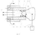
На фиг. 1 приведена блок-схема устройства, где 1 - источник лазерного излучения, 2 - лазерный наконечник, 3 - устройство ирригации - аспирации, 4 - наконечник устройства ирригации-аспирации, 5 - устройство для концентрации лазерно-индуцированной акустической волны, 6 - устройство преобразования лазерного излучения в энергию акустической волны, 7 - объект (хрусталик глаза или его фрагмент). In FIG. 1 is a block diagram of a device where 1 is a laser radiation source, 2 is a laser tip, 3 is an irrigation – aspiration device, 4 is an irrigation-aspiration device tip, 5 is a device for concentrating a laser-induced acoustic wave, 6 is a laser conversion device radiation into the energy of an acoustic wave; 7 — an object (lens of the eye or its fragment).
На фиг. 2 изображен вариант, при котором поверхность устройства для концентрации лазерно-индуцированной акустической волны (концентратор) 5 представляет собой разомкнутую криволинейную поверхность по крайней мере второго порядка (концентратор 5 может быть в виде полого стержня). In FIG. 2 shows a variant in which the surface of the device for concentrating a laser-induced acoustic wave (hub) 5 is an open curved surface of at least second order (the
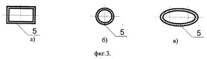
Виды поперечных сечений устройства для концентрации лазерно-индуцированной акустической волны 5, выполненного в виде полого стержня, стенки которого прозрачны на длине волны лазерного излучения, представлены на фиг.3. На фиг. 3а представлено поперечное сечение в виде прямоугольника, на фиг. 3б - круга, на фиг. 3в - эллипса. The types of cross-sections of the device for the concentration of laser-induced
На фиг. 4 представлено устройство преобразования лазерного излучения в энергию акустической волны 6, образованное путем нанесения на поверхности устройства для концентрации лазерно-индуцированной акустической волны 5 материала, поглощающего лазерное излучение. In FIG. 4 shows a device for converting laser radiation into energy of an
На фиг. 5 изображен вариант, при котором между устройством преобразования лазерного излучения в энергию акустической волны 6 и устройством для концентрации лазерно-индуцированной акустической волны 5 имеется пространство, заполненное материалом 8, акустическое сопротивление которого меньше, чем 100 кг (м2•с).In FIG. 5 shows an embodiment in which there is a space filled with
На фиг. 6 изображено устройство преобразования лазерного излучения в энергию акустической волны 6, выполненное в виде прямой (фиг. 6а) или изогнутой (фиг. 6б) полосы, нанесенной на внешнюю поверхность устройства для концентрации лазерно-индуцированной акустической волны 5 (вариант нанесения аналогичных полос на внутреннюю поверхность на чертежах не показан). In FIG. 6 shows a device for converting laser radiation into energy of an
На фиг. 7 изображен вариант, при котором устройство преобразования лазерного излучения в энергию акустической волны 6 нанесено на внешнюю поверхность устройства для концентрации лазерно-индуцированной акустической волны 5, а поверхность устройства преобразования лазерного излучения в энергию акустической волны представляет собой по крайней мере одну поверхность эллиптического типа (вариант нанесения на внутреннюю поверхность на чертежах не показан). In FIG. 7 shows an embodiment in which the device for converting laser radiation into
На фиг. 8 приведен вариант, при котором устройство преобразования лазерного излучения в энергию акустической волны 6 расположено внутри стенок устройства для концентрации лазерно-индуцированной акустической волны 5. In FIG. 8 shows an embodiment in which a device for converting laser radiation into energy of an
На фиг. 9 приведен вид устройства, при котором устройство для концентрации лазерно-индуцированной акустической волны 5 имеет углубления, заполненные материалом устройства преобразования лазерного излучения в энергию акустической волны 6. Вид устройства для концентрации лазерно-индуцированной акустической волны 5, поверхность которого представляет собой усеченную поверхность вращения по крайней мере второго порядка, приведен на фиг.10. In FIG. 9 is a view of a device in which a device for concentrating a laser-induced
Блок-схема устройства, в котором источник лазерного излучения 1 дополнительно содержит модулятор 9, частота модуляции которого равна или кратна резонансной частоте устройства для концентрации лазерно-индуцированной волны 5 приведена на фиг.11. A block diagram of a device in which the
На фиг. 12 изображен вариант устройства, при котором продольные оси лазерного наконечника 2 и устройства для концентрации лазерно-индуцированной акустической волны 5 направлены под углом α друг к другу. In FIG. 12 shows a variant of the device in which the longitudinal axis of the
В данном примере описан вариант, в котором устройство для концентрации акустической волны и устройство для преобразования лазерного излучения выполнены в виде единого целого. Устройство работает следующим образом (см. фиг.13). В переднюю камеру глаза 10 через 2-миллиметровый основной разрез 11 вводится наконечник 4 устройства ирригации-аспирации 3, содержащий устройство для концентрации акустической волны (концентратор) 5 и устройство для преобразования лазерного излучения в акустическую волну 6 (преобразователь). Через дополнительный разрез 12 у лимба в 80-90o от основного разреза 11 в переднюю камеру 10 вводят лазерный наконечник 2. Наконечник 4 устройства ирригации-аспирации 3 содержит две полые трубки (стержня) 13, 14 (см. фиг. 14). Внешняя металлическая трубка 13 служит для ирригации 15. Внутренняя трубка 14 имеет стенки, прозрачные для излучения, с длиной волны, генерируемой лазером, и содержит концентратор 5, преобразователь 6 и аспирационный канал 16, через который происходит аспирация 17. Включают устройство ирригации-аспирации 3, при этом поддерживают стабильный объем передней камеры 10. Наконечник 4 (фиг. 13), содержащий концентратор 5 и преобразователь 6, располагают так, чтобы конец внутренней трубки 14 контактировал с поверхностью хрусталика 7. Включается источник лазерного излучения 1. Лазерное излучение 18 направляется на поверхность хрусталика в 1-2 мм от края внутренней трубки 14. Оконечный оптический элемент 19 (в данном случае дистальный торец оптического волокна) лазерного наконечника 2 при этом располагается на расстоянии порядка 1 мм от поверхности хрусталика 7. Лазерное излучение 18, взаимодействуя с веществом хрусталика 7, частично преобразуется в акустическую волну 20. Акустическая волна 20 распространяется в передней камере 10 и попадает в полую трубку 14, содержащую концентратор 5 и преобразователь 6. Акустическая волна 20, попадая внутрь полой трубки 14, многократно отражается от концентратора 5, роль которого играет внутренняя поверхность трубки 14, и фокусируется на поверхность хрусталика 7, вызывая локальные дефекты за счет фрагментации хрусталиковых фибрилл. Перемещение лазерного наконечника 2 над поверхностью хрусталика 7 приводит к расширению дефекта и образованию кратера в хрусталике 7. Дальнейшее облучение дна кратера в хрусталике 7 приводит к разделению хрусталика 7 (см. фиг. 15) на несколько отдельных хрусталиковых сегментов 21. Далее производят удаление хрусталиковых сегментов 21. Этот этап операции начинается с присасывания одного из хрусталиковых сегментов 21 (см. фиг. 16) к входному отверстию аспирационного канала 16 трубки 14. Лазерное излучение 18 направляется на поверхность хрусталикового сегмента 21. Образующая акустическая волна 20, распространяясь по материалу хрусталикового сегмента 21, достигает концентратора 5, роль которого играет внутренняя поверхность трубки 14 и, отражаясь от нее, фокусируется внутрь хрусталикового сегмента 21, вызывая дополнительный его раскол с образованием множества микротрещин. Дальнейшее лазерное и акустическое воздействие приводит к расколу фиксированного к входному отверстию аспирационного канала 16 хрусталикового сегмента 21 на множественные фрагменты 22, которые только частично связаны друг с другом. В этот момент наблюдается вхождение образовавшихся мелких хрусталиковых фрагментов 22 в аспирационный канал 16. Затем (см. фиг. 17) лазерное излучение 18 направляется на край трубки 14. Излучение 18 при этом поглощается материалом преобразователя 6 и трансформируется в дополнительные акустические колебания 23. Дополнительные акустические колебания 23 фокусируются концентратором 5 на хрусталиковый фрагмент 22 внутри трубки 14, дополнительно дефрагментируя последние, что приводит к их полной аспирации из аспирационного канала 16. По мере прохождения по аспирационному каналу 16 трубки 14 одного хрусталикового фрагмента 22 во входное отверстие аспирационного канала 16 входит следующий хрусталиковый фрагмент 22. Воздействие лазерного излучения 18, направленного на край полой трубки, содержащей концентратор 5 и преобразователь 6, в течение всего времени данного этапа операции позволяет последовательно удалять входящие друг за другом хрусталиковые фрагменты 22. После удаления одного хрусталикового сегмента 21, прососанного изначально к входному отверстию аспирационного канала 16, приступают к удалению оставшихся хрусталиковых сегментов 21 хрусталика 7 по описанной выше схеме, до полного удаления хрусталика 7.In this example, a variant is described in which a device for concentrating an acoustic wave and a device for converting laser radiation are made as a single unit. The device operates as follows (see Fig.13). In the front camera of the
Таким образом, одновременное действие концентратора 5 и преобразователя 6 является необходимым и достаточным для однозначного получения твердых хрусталиковых масс. Thus, the simultaneous action of the
Claims (19)
Priority Applications (3)
| Application Number | Priority Date | Filing Date | Title |
|---|---|---|---|
| RU97120606/14A RU2130762C1 (en) | 1997-12-10 | 1997-12-10 | Device for performing ophthalmosurgical operations |
| DE19856677A DE19856677B4 (en) | 1997-12-10 | 1998-12-09 | Device for cataract surgery |
| US09/209,402 US6322557B1 (en) | 1997-12-10 | 1998-12-10 | Device for removing cataracts |
Applications Claiming Priority (1)
| Application Number | Priority Date | Filing Date | Title |
|---|---|---|---|
| RU97120606/14A RU2130762C1 (en) | 1997-12-10 | 1997-12-10 | Device for performing ophthalmosurgical operations |
Publications (1)
| Publication Number | Publication Date |
|---|---|
| RU2130762C1 true RU2130762C1 (en) | 1999-05-27 |
Family
ID=20199942
Family Applications (1)
| Application Number | Title | Priority Date | Filing Date |
|---|---|---|---|
| RU97120606/14A RU2130762C1 (en) | 1997-12-10 | 1997-12-10 | Device for performing ophthalmosurgical operations |
Country Status (3)
| Country | Link |
|---|---|
| US (1) | US6322557B1 (en) |
| DE (1) | DE19856677B4 (en) |
| RU (1) | RU2130762C1 (en) |
Cited By (9)
| Publication number | Priority date | Publication date | Assignee | Title |
|---|---|---|---|---|
| RU2196558C2 (en) * | 2000-10-03 | 2003-01-20 | Государственное учреждение Межотраслевой научно-технический комплекс "Микрохирургия глаза" | Device for building laser radiation pattern |
| RU2201186C2 (en) * | 2000-05-12 | 2003-03-27 | Государственное учреждение Межотраслевой научно-технический комплекс "Микрохирургия глаза" | Method for extracting cataract |
| WO2003039416A1 (en) * | 2001-11-08 | 2003-05-15 | Evgeny Nikolaevich Ananiev | Method for intracapsular destruction of a cataract-altered crystalline lens and device for carrying out said method |
| RU2341239C2 (en) * | 2006-07-18 | 2008-12-20 | Владимир Алексеевич Старостин | Laser tip-manipulator |
| RU2363429C1 (en) * | 2008-02-12 | 2009-08-10 | Федеральное государственное учреждение "Межотраслевой научно-технический комплекс "Микрохирургия глаза" имени академика С.Н. Федорова Федерального агентства по высокотехнологичной медицинской помощи" | Irrigation device |
| RU2463028C2 (en) * | 2007-03-14 | 2012-10-10 | Уэйвлайт Аг | Device for fixation of element to eye |
| RU2575051C2 (en) * | 2011-05-06 | 2016-02-10 | Алькон Рисерч, Лтд. | Illuminated microsurgical instrument comprising oblique optical fibre |
| US9561085B2 (en) | 2011-05-06 | 2017-02-07 | Alcon Research Ltd. | Illuminated microsurgical instrument including optical fiber with beveled end face |
| RU2708211C2 (en) * | 2016-08-05 | 2019-12-04 | Уэйвлайт Гмбх | Laser system for eye surgery and set of contact devices for use in laser device for eye surgery |
Families Citing this family (81)
| Publication number | Priority date | Publication date | Assignee | Title |
|---|---|---|---|---|
| DE19852574A1 (en) * | 1998-11-06 | 2000-05-11 | Aesculap Meditec Gmbh | Medical instrument for phacoemulsification |
| US6733491B2 (en) * | 2001-09-07 | 2004-05-11 | Advanced Medical Optics | Cataract extraction apparatus and method |
| US7182759B2 (en) * | 2001-09-07 | 2007-02-27 | Advanced Medical Optics, Inc. | Cataract extraction apparatus and method with rapid pulse phaco power |
| US20030208218A1 (en) * | 2002-05-02 | 2003-11-06 | Kenneth E. Kadziauskas | Ultrasonic needle cover |
| US20040158236A1 (en) * | 2003-02-12 | 2004-08-12 | Reinhardt Thyzel | Surgical needle with laser target |
| DE102004021754A1 (en) * | 2004-04-30 | 2005-11-24 | Reinhardt Thyzel | Device for removing epithelial cells from a lens capsular bag of a human or animal eye |
| WO2006067699A1 (en) * | 2004-12-20 | 2006-06-29 | Koninklijke Philips Electronics N.V. | Investigation of body structures |
| US12290277B2 (en) | 2007-01-02 | 2025-05-06 | Aquabeam, Llc | Tissue resection with pressure sensing |
| US8814921B2 (en) | 2008-03-06 | 2014-08-26 | Aquabeam Llc | Tissue ablation and cautery with optical energy carried in fluid stream |
| US9232959B2 (en) | 2007-01-02 | 2016-01-12 | Aquabeam, Llc | Multi fluid tissue resection methods and devices |
| US8764782B2 (en) * | 2008-10-31 | 2014-07-01 | Art, Limited | Phacoemulsification needle |
| US9528893B2 (en) | 2009-06-29 | 2016-12-27 | University Of Massachusetts | Optical fiber pressure sensor with uniform diaphragm and method of fabricating same |
| WO2011050164A1 (en) | 2009-10-21 | 2011-04-28 | Avedro, Inc. | Eye therapy |
| JP6377906B2 (en) | 2010-03-19 | 2018-08-22 | アヴェドロ・インコーポレーテッドAvedro,Inc. | System for applying and monitoring eye treatment |
| DE102010047060A1 (en) * | 2010-09-30 | 2012-04-05 | Carl Zeiss Meditec Ag | Diagnosis of dementia, preferably Alzheimer's disease, comprises supplying extracted components from a suction to an analysis unit and analyzing components in analysis unit for presence of e.g. paired helical filaments-tau plaques |
| US9050171B2 (en) | 2010-10-04 | 2015-06-09 | William J. Foster | Small diameter fragmatome for minimally traumatic retained lens fragments removal |
| US20120191079A1 (en) | 2011-01-20 | 2012-07-26 | Hansen Medical, Inc. | System and method for endoluminal and translumenal therapy |
| WO2012112890A2 (en) | 2011-02-17 | 2012-08-23 | University Of Massachusetts | Photoacoustic probe |
| US9044308B2 (en) | 2011-05-24 | 2015-06-02 | Avedro, Inc. | Systems and methods for reshaping an eye feature |
| EP2713849B1 (en) | 2011-06-02 | 2017-02-15 | Avedro, Inc. | Systems for monitoring time based photo active agent delivery or photo active marker presence |
| US9452084B2 (en) * | 2011-09-06 | 2016-09-27 | Art, Limited | Apparatus and method for phacoemulsification |
| WO2013052511A2 (en) * | 2011-10-02 | 2013-04-11 | Avedro, Inc. | Systems and methods for applying and monitoring eye therapy |
| CN108606773B (en) | 2012-02-29 | 2020-08-11 | 普罗赛普特生物机器人公司 | Automated image-guided tissue resection and processing |
| EP4074294A1 (en) | 2012-07-16 | 2022-10-19 | Avedro, Inc. | Systems and methods for corneal cross-linking with pulsed light |
| US10231867B2 (en) | 2013-01-18 | 2019-03-19 | Auris Health, Inc. | Method, apparatus and system for a water jet |
| WO2014201165A1 (en) | 2013-06-11 | 2014-12-18 | Auris Surgical Robotics, Inc. | System for robotic assisted cataract surgery |
| US9498122B2 (en) | 2013-06-18 | 2016-11-22 | Avedro, Inc. | Systems and methods for determining biomechanical properties of the eye for applying treatment |
| US9498114B2 (en) | 2013-06-18 | 2016-11-22 | Avedro, Inc. | Systems and methods for determining biomechanical properties of the eye for applying treatment |
| US10426661B2 (en) | 2013-08-13 | 2019-10-01 | Auris Health, Inc. | Method and apparatus for laser assisted cataract surgery |
| WO2015143308A1 (en) | 2014-03-20 | 2015-09-24 | Medical Instrument Development Laboratories, Inc. | Aspirating cutter and method to use |
| JP6644799B2 (en) | 2014-10-27 | 2020-02-12 | アヴェドロ・インコーポレーテッドAvedro,Inc. | System and method for ocular crosslinking treatment |
| WO2016077747A1 (en) | 2014-11-13 | 2016-05-19 | Avedro, Inc. | Multipass virtually imaged phased array etalon |
| US20160287279A1 (en) | 2015-04-01 | 2016-10-06 | Auris Surgical Robotics, Inc. | Microsurgical tool for robotic applications |
| EP3827792A1 (en) | 2015-04-24 | 2021-06-02 | Avedro, Inc. | Systems and methods for photoactivating a photosensitizer applied to an eye |
| US10028657B2 (en) | 2015-05-22 | 2018-07-24 | Avedro, Inc. | Systems and methods for monitoring cross-linking activity for corneal treatments |
| ES2873108T3 (en) | 2015-07-13 | 2021-11-03 | Alcon Inc | Vitreous cutter with integrated lighting system |
| WO2017015471A1 (en) | 2015-07-21 | 2017-01-26 | Avedro, Inc. | Systems and methods for treaments of an eye with a photosensitizer |
| US9949749B2 (en) | 2015-10-30 | 2018-04-24 | Auris Surgical Robotics, Inc. | Object capture with a basket |
| US9955986B2 (en) | 2015-10-30 | 2018-05-01 | Auris Surgical Robotics, Inc. | Basket apparatus |
| US10639108B2 (en) | 2015-10-30 | 2020-05-05 | Auris Health, Inc. | Process for percutaneous operations |
| US10624785B2 (en) | 2016-01-30 | 2020-04-21 | Carl Zeiss Meditec Cataract Technology Inc. | Devices and methods for ocular surgery |
| KR102545869B1 (en) | 2017-03-28 | 2023-06-23 | 아우리스 헬스, 인코포레이티드 | shaft operating handle |
| US10285574B2 (en) | 2017-04-07 | 2019-05-14 | Auris Health, Inc. | Superelastic medical instrument |
| EP3606400B1 (en) | 2017-04-07 | 2022-03-09 | Auris Health, Inc. | Patient introducer alignment |
| US11278450B2 (en) | 2017-05-04 | 2022-03-22 | Carl Zeiss Meditec Cataract Technology Inc. | Devices and methods for ocular surgery |
| CN117137718A (en) | 2018-03-05 | 2023-12-01 | 艾维德洛公司 | Systems and methods for eye tracking during eye treatment |
| US11766356B2 (en) | 2018-03-08 | 2023-09-26 | Avedro, Inc. | Micro-devices for treatment of an eye |
| WO2019236615A1 (en) | 2018-06-05 | 2019-12-12 | Carl Zeiss Meditec Cataract Technology Inc. | Ophthalmic microsurgical tools, systems, and methods of use |
| US10751140B2 (en) | 2018-06-07 | 2020-08-25 | Auris Health, Inc. | Robotic medical systems with high force instruments |
| US11399905B2 (en) | 2018-06-28 | 2022-08-02 | Auris Health, Inc. | Medical systems incorporating pulley sharing |
| US10828118B2 (en) | 2018-08-15 | 2020-11-10 | Auris Health, Inc. | Medical instruments for tissue cauterization |
| CN112566567B (en) | 2018-08-17 | 2024-10-29 | 奥瑞斯健康公司 | Bipolar Medical Devices |
| US12144546B2 (en) | 2018-09-19 | 2024-11-19 | Avedro, Inc. | Systems and methods for eye tracking during eye treatment |
| CN113329723A (en) | 2018-09-19 | 2021-08-31 | 艾维德洛公司 | Systems and methods for treating corneal ectasia-type disease |
| CN112770689B (en) | 2018-09-26 | 2024-07-19 | 奥瑞斯健康公司 | Systems and instruments for suction and irrigation |
| WO2020076447A1 (en) | 2018-10-08 | 2020-04-16 | Auris Health, Inc. | Systems and instruments for tissue sealing |
| AU2019356934B2 (en) | 2018-10-09 | 2024-10-17 | Avedro, Inc. | Photoactivation systems and methods for corneal cross-linking treatments |
| EP3870075B1 (en) | 2018-12-20 | 2025-06-11 | Auris Health, Inc. | Shielding for wristed instruments |
| CN113347938A (en) | 2019-01-25 | 2021-09-03 | 奥瑞斯健康公司 | Vascular sealer with heating and cooling capabilities |
| CA3128071A1 (en) | 2019-02-01 | 2020-08-06 | Carl Zeiss Meditec Cataract Technology Inc. | Ophthalmic cutting instruments having integrated aspiration pump |
| JP7571038B2 (en) | 2019-02-26 | 2024-10-22 | アヴェドロ・インコーポレーテッド | Systems and methods for ophthalmic cross-linking procedures |
| WO2020197625A1 (en) | 2019-03-25 | 2020-10-01 | Auris Health, Inc. | Systems and methods for medical stapling |
| AU2020277300C1 (en) | 2019-05-17 | 2025-04-03 | Carl Zeiss Meditec Cataract Technology Inc. | Ophthalmic cutting instruments having integrated aspiration pump |
| JP7455868B2 (en) | 2019-06-07 | 2024-03-26 | カール・ツァイス・メディテック・キャタラクト・テクノロジー・インコーポレイテッド | Multi-Stage Trigger for Ophthalmic Cutting Tools |
| US12138003B2 (en) | 2019-06-25 | 2024-11-12 | Auris Health, Inc. | Medical instruments including wrists with hybrid redirect surfaces |
| US11369386B2 (en) | 2019-06-27 | 2022-06-28 | Auris Health, Inc. | Systems and methods for a medical clip applier |
| WO2020263949A1 (en) | 2019-06-28 | 2020-12-30 | Auris Health, Inc. | Medical instruments including wrists with hybrid redirect surfaces |
| EP4009928A4 (en) | 2019-08-06 | 2023-08-02 | Avedro, Inc. | Photoactivation systems and methods for corneal cross-linking treatments |
| US11896330B2 (en) | 2019-08-15 | 2024-02-13 | Auris Health, Inc. | Robotic medical system having multiple medical instruments |
| CN114502094A (en) | 2019-09-26 | 2022-05-13 | 奥瑞斯健康公司 | System and method for collision detection and avoidance |
| WO2021059100A1 (en) | 2019-09-26 | 2021-04-01 | Auris Health, Inc. | Systems and methods for collision avoidance using object models |
| US11737845B2 (en) | 2019-09-30 | 2023-08-29 | Auris Inc. | Medical instrument with a capstan |
| US11737835B2 (en) | 2019-10-29 | 2023-08-29 | Auris Health, Inc. | Braid-reinforced insulation sheath |
| US12357409B2 (en) | 2019-11-21 | 2025-07-15 | Auris Health, Inc. | Systems and methods for draping a surgical system |
| CN114901200A (en) | 2019-12-31 | 2022-08-12 | 奥瑞斯健康公司 | Advanced basket drive mode |
| US11950872B2 (en) | 2019-12-31 | 2024-04-09 | Auris Health, Inc. | Dynamic pulley system |
| EP4125689A4 (en) | 2020-03-30 | 2024-04-17 | Auris Health, Inc. | Workspace optimization for robotic surgery |
| EP4171427A4 (en) | 2020-06-29 | 2024-08-07 | Auris Health, Inc. | SYSTEMS AND METHODS FOR DETECTING CONTACT BETWEEN A LINK AND AN EXTERNAL OBJECT |
| US11357586B2 (en) | 2020-06-30 | 2022-06-14 | Auris Health, Inc. | Systems and methods for saturated robotic movement |
| CN115734765A (en) | 2020-06-30 | 2023-03-03 | 奥瑞斯健康公司 | Robotic medical system with crash proximity indicator |
| AU2022232309A1 (en) | 2021-03-08 | 2023-10-12 | Avedro, Inc. | Systems and methods for generating patient-specific corneal cross-linking treatment patterns |
Citations (2)
| Publication number | Priority date | Publication date | Assignee | Title |
|---|---|---|---|---|
| EP0467775A1 (en) * | 1990-07-19 | 1992-01-22 | Kabushiki Kaisha TOPCON | Lens capsule laser cutting apparatus |
| US5139504A (en) * | 1987-05-01 | 1992-08-18 | Ophthalmocare, Inc. | Apparatus, system, and method for softening and extracting cataractous tissue |
Family Cites Families (11)
| Publication number | Priority date | Publication date | Assignee | Title |
|---|---|---|---|---|
| US4744360A (en) * | 1986-12-18 | 1988-05-17 | Bath Patricia E | Apparatus for ablating and removing cataract lenses |
| US5057098A (en) * | 1987-05-01 | 1991-10-15 | Ophthalmocare, Inc. | Apparatus and method for extracting cataract tissue |
| US4825865A (en) * | 1987-05-01 | 1989-05-02 | Jerry Zelman | Apparatus and method for extracting cataract tissue |
| ATE150284T1 (en) * | 1989-10-25 | 1997-04-15 | Jack Murray Dodick | SURGICAL INSTRUMENT WITH INPUT POWER CONVERTER |
| US5957914A (en) * | 1990-06-19 | 1999-09-28 | Surgical Laser Technologies, Inc. | Photo optic breakdown probe |
| US5257988A (en) * | 1991-07-19 | 1993-11-02 | L'esperance Medical Technologies, Inc. | Apparatus for phacoemulsifying cataractous-lens tissue within a protected environment |
| US5370641A (en) * | 1992-05-22 | 1994-12-06 | O'donnell, Jr.; Francis E. | Laser trabeculodissection |
| US5643250A (en) * | 1992-08-07 | 1997-07-01 | O'donnell, Jr.; Francis E. | Laser probe hand piece |
| WO1994022402A1 (en) * | 1993-03-31 | 1994-10-13 | Davis Peter L | Phacoemulsification method and tip |
| US5445637A (en) * | 1993-12-06 | 1995-08-29 | American Cyanamid Company | Method and apparatus for preventing posterior capsular opacification |
| US5733276A (en) * | 1996-08-20 | 1998-03-31 | Ramot University Authority For Applied Research & Industrial Development Ltd. | Method for prophylactic therapy for post-operative posterior capsular opacification |
-
1997
- 1997-12-10 RU RU97120606/14A patent/RU2130762C1/en not_active IP Right Cessation
-
1998
- 1998-12-09 DE DE19856677A patent/DE19856677B4/en not_active Expired - Fee Related
- 1998-12-10 US US09/209,402 patent/US6322557B1/en not_active Expired - Fee Related
Patent Citations (2)
| Publication number | Priority date | Publication date | Assignee | Title |
|---|---|---|---|---|
| US5139504A (en) * | 1987-05-01 | 1992-08-18 | Ophthalmocare, Inc. | Apparatus, system, and method for softening and extracting cataractous tissue |
| EP0467775A1 (en) * | 1990-07-19 | 1992-01-22 | Kabushiki Kaisha TOPCON | Lens capsule laser cutting apparatus |
Non-Patent Citations (1)
| Title |
|---|
| 1. Проспект фирмы Premier Laser System. - 1996. 2. * |
Cited By (9)
| Publication number | Priority date | Publication date | Assignee | Title |
|---|---|---|---|---|
| RU2201186C2 (en) * | 2000-05-12 | 2003-03-27 | Государственное учреждение Межотраслевой научно-технический комплекс "Микрохирургия глаза" | Method for extracting cataract |
| RU2196558C2 (en) * | 2000-10-03 | 2003-01-20 | Государственное учреждение Межотраслевой научно-технический комплекс "Микрохирургия глаза" | Device for building laser radiation pattern |
| WO2003039416A1 (en) * | 2001-11-08 | 2003-05-15 | Evgeny Nikolaevich Ananiev | Method for intracapsular destruction of a cataract-altered crystalline lens and device for carrying out said method |
| RU2341239C2 (en) * | 2006-07-18 | 2008-12-20 | Владимир Алексеевич Старостин | Laser tip-manipulator |
| RU2463028C2 (en) * | 2007-03-14 | 2012-10-10 | Уэйвлайт Аг | Device for fixation of element to eye |
| RU2363429C1 (en) * | 2008-02-12 | 2009-08-10 | Федеральное государственное учреждение "Межотраслевой научно-технический комплекс "Микрохирургия глаза" имени академика С.Н. Федорова Федерального агентства по высокотехнологичной медицинской помощи" | Irrigation device |
| RU2575051C2 (en) * | 2011-05-06 | 2016-02-10 | Алькон Рисерч, Лтд. | Illuminated microsurgical instrument comprising oblique optical fibre |
| US9561085B2 (en) | 2011-05-06 | 2017-02-07 | Alcon Research Ltd. | Illuminated microsurgical instrument including optical fiber with beveled end face |
| RU2708211C2 (en) * | 2016-08-05 | 2019-12-04 | Уэйвлайт Гмбх | Laser system for eye surgery and set of contact devices for use in laser device for eye surgery |
Also Published As
| Publication number | Publication date |
|---|---|
| US6322557B1 (en) | 2001-11-27 |
| DE19856677A1 (en) | 1999-06-17 |
| DE19856677B4 (en) | 2004-07-08 |
Similar Documents
| Publication | Publication Date | Title |
|---|---|---|
| RU2130762C1 (en) | Device for performing ophthalmosurgical operations | |
| KR100422735B1 (en) | Therapeutic treatment magnetic treatment device | |
| FI110482B (en) | Device for the treatment of vascular damage | |
| KR100434195B1 (en) | Surgical laser device and its use method | |
| US6709269B1 (en) | Apparatus and method for the processing of solid materials, including hard tissues | |
| CA1328486C (en) | Method and apparatus for laser surgery | |
| JP3113274B2 (en) | Surgical device with input power converter | |
| US5620478A (en) | Method and apparatus for therapeutic electromagnetic treatment | |
| US20090227992A1 (en) | Shock-Wave Generating Device, Such as for the Treatment of Calcific Aortic Stenosis | |
| US5993439A (en) | Lens shield for laser skin perforation | |
| CN1960682B (en) | device for hair removal | |
| CA2180616A1 (en) | Method and apparatus for therapeutic electromagnetic treatment | |
| JP2001000442A (en) | Cutting by electromagnetic induction using liquid mist particles for application to skin science | |
| JP2012502677A5 (en) | ||
| Gitomer et al. | Laser-produced plasmas in medicine | |
| WO1995024867A1 (en) | Laser energy concentration in laser powered surgical instrument | |
| JP2002517159A (en) | Apparatus and method for laser vaporization removal of hard tissue | |
| RU2157158C2 (en) | Gear for ophthalmologic surgical operations | |
| JPH1033557A (en) | Dental gas laser device | |
| Sterenborg et al. | Laserlithotripsy of salivary stones: a comparison between the pulsed dye laser and the Ho-YSGG laser | |
| JPH10506314A (en) | Pulse emission laser device used in the medical field | |
| RU97116980A (en) | METHOD FOR TREATING CHRONIC HYPERTROPHIC, VASOMOTOR AND ALLERGIC RHINITIES | |
| RU2309700C1 (en) | Method for treating benign laryngeal neoplasms | |
| WO2000062694A1 (en) | Apparatus and method for the processing of solid materials, including hard tissues | |
| JPS6058970B2 (en) | Laser scalpel device |
Legal Events
| Date | Code | Title | Description |
|---|---|---|---|
| MM4A | The patent is invalid due to non-payment of fees |
Effective date: 20051211 |
|
| NF4A | Reinstatement of patent |
Effective date: 20070610 |
|
| MM4A | The patent is invalid due to non-payment of fees |
Effective date: 20111211 |