RU2044606C1 - Method of obtaining surfaces with alternative projections and hollows (variants) and tool for its realization - Google Patents
Method of obtaining surfaces with alternative projections and hollows (variants) and tool for its realization Download PDFInfo
- Publication number
- RU2044606C1 RU2044606C1 RU9393017599A RU93017599A RU2044606C1 RU 2044606 C1 RU2044606 C1 RU 2044606C1 RU 9393017599 A RU9393017599 A RU 9393017599A RU 93017599 A RU93017599 A RU 93017599A RU 2044606 C1 RU2044606 C1 RU 2044606C1
- Authority
- RU
- Russia
- Prior art keywords
- tool
- protrusions
- workpiece
- processing
- profile
- Prior art date
Links
Images


Classifications
-
- F—MECHANICAL ENGINEERING; LIGHTING; HEATING; WEAPONS; BLASTING
- F28—HEAT EXCHANGE IN GENERAL
- F28F—DETAILS OF HEAT-EXCHANGE AND HEAT-TRANSFER APPARATUS, OF GENERAL APPLICATION
- F28F3/00—Plate-like or laminated elements; Assemblies of plate-like or laminated elements
- F28F3/02—Elements or assemblies thereof with means for increasing heat-transfer area, e.g. with fins, with recesses, with corrugations
- F28F3/04—Elements or assemblies thereof with means for increasing heat-transfer area, e.g. with fins, with recesses, with corrugations the means being integral with the element
- F28F3/048—Elements or assemblies thereof with means for increasing heat-transfer area, e.g. with fins, with recesses, with corrugations the means being integral with the element in the form of ribs integral with the element or local variations in thickness of the element, e.g. grooves, microchannels
-
- B—PERFORMING OPERATIONS; TRANSPORTING
- B21—MECHANICAL METAL-WORKING WITHOUT ESSENTIALLY REMOVING MATERIAL; PUNCHING METAL
- B21C—MANUFACTURE OF METAL SHEETS, WIRE, RODS, TUBES, PROFILES OR LIKE SEMI-MANUFACTURED PRODUCTS OTHERWISE THAN BY ROLLING; AUXILIARY OPERATIONS USED IN CONNECTION WITH METAL-WORKING WITHOUT ESSENTIALLY REMOVING MATERIAL
- B21C37/00—Manufacture of metal sheets, rods, wire, tubes, profiles or like semi-manufactured products, not otherwise provided for; Manufacture of tubes of special shape
- B21C37/06—Manufacture of metal sheets, rods, wire, tubes, profiles or like semi-manufactured products, not otherwise provided for; Manufacture of tubes of special shape of tubes or metal hoses; Combined procedures for making tubes, e.g. for making multi-wall tubes
- B21C37/15—Making tubes of special shape; Making tube fittings
- B21C37/20—Making helical or similar guides in or on tubes without removing material, e.g. by drawing same over mandrels, by pushing same through dies ; Making tubes with angled walls, ribbed tubes or tubes with decorated walls
- B21C37/207—Making helical or similar guides in or on tubes without removing material, e.g. by drawing same over mandrels, by pushing same through dies ; Making tubes with angled walls, ribbed tubes or tubes with decorated walls with helical guides
-
- B—PERFORMING OPERATIONS; TRANSPORTING
- B21—MECHANICAL METAL-WORKING WITHOUT ESSENTIALLY REMOVING MATERIAL; PUNCHING METAL
- B21J—FORGING; HAMMERING; PRESSING METAL; RIVETING; FORGE FURNACES
- B21J5/00—Methods for forging, hammering, or pressing; Special equipment or accessories therefor
- B21J5/06—Methods for forging, hammering, or pressing; Special equipment or accessories therefor for performing particular operations
- B21J5/068—Shaving, skiving or scarifying for forming lifted portions, e.g. slices or barbs, on the surface of the material
-
- B—PERFORMING OPERATIONS; TRANSPORTING
- B23—MACHINE TOOLS; METAL-WORKING NOT OTHERWISE PROVIDED FOR
- B23B—TURNING; BORING
- B23B5/00—Turning-machines or devices specially adapted for particular work; Accessories specially adapted therefor
-
- B—PERFORMING OPERATIONS; TRANSPORTING
- B23—MACHINE TOOLS; METAL-WORKING NOT OTHERWISE PROVIDED FOR
- B23C—MILLING
- B23C3/00—Milling particular work; Special milling operations; Machines therefor
-
- B—PERFORMING OPERATIONS; TRANSPORTING
- B23—MACHINE TOOLS; METAL-WORKING NOT OTHERWISE PROVIDED FOR
- B23P—METAL-WORKING NOT OTHERWISE PROVIDED FOR; COMBINED OPERATIONS; UNIVERSAL MACHINE TOOLS
- B23P15/00—Making specific metal objects by operations not covered by a single other subclass or a group in this subclass
- B23P15/26—Making specific metal objects by operations not covered by a single other subclass or a group in this subclass heat exchangers or the like
-
- F—MECHANICAL ENGINEERING; LIGHTING; HEATING; WEAPONS; BLASTING
- F28—HEAT EXCHANGE IN GENERAL
- F28F—DETAILS OF HEAT-EXCHANGE AND HEAT-TRANSFER APPARATUS, OF GENERAL APPLICATION
- F28F1/00—Tubular elements; Assemblies of tubular elements
- F28F1/10—Tubular elements and assemblies thereof with means for increasing heat-transfer area, e.g. with fins, with projections, with recesses
- F28F1/12—Tubular elements and assemblies thereof with means for increasing heat-transfer area, e.g. with fins, with projections, with recesses the means being only outside the tubular element
- F28F1/24—Tubular elements and assemblies thereof with means for increasing heat-transfer area, e.g. with fins, with projections, with recesses the means being only outside the tubular element and extending transversely
- F28F1/26—Tubular elements and assemblies thereof with means for increasing heat-transfer area, e.g. with fins, with projections, with recesses the means being only outside the tubular element and extending transversely the means being integral with the element
-
- F—MECHANICAL ENGINEERING; LIGHTING; HEATING; WEAPONS; BLASTING
- F28—HEAT EXCHANGE IN GENERAL
- F28F—DETAILS OF HEAT-EXCHANGE AND HEAT-TRANSFER APPARATUS, OF GENERAL APPLICATION
- F28F1/00—Tubular elements; Assemblies of tubular elements
- F28F1/10—Tubular elements and assemblies thereof with means for increasing heat-transfer area, e.g. with fins, with projections, with recesses
- F28F1/12—Tubular elements and assemblies thereof with means for increasing heat-transfer area, e.g. with fins, with projections, with recesses the means being only outside the tubular element
- F28F1/34—Tubular elements and assemblies thereof with means for increasing heat-transfer area, e.g. with fins, with projections, with recesses the means being only outside the tubular element and extending obliquely
- F28F1/36—Tubular elements and assemblies thereof with means for increasing heat-transfer area, e.g. with fins, with projections, with recesses the means being only outside the tubular element and extending obliquely the means being helically wound fins or wire spirals
-
- F—MECHANICAL ENGINEERING; LIGHTING; HEATING; WEAPONS; BLASTING
- F28—HEAT EXCHANGE IN GENERAL
- F28F—DETAILS OF HEAT-EXCHANGE AND HEAT-TRANSFER APPARATUS, OF GENERAL APPLICATION
- F28F13/00—Arrangements for modifying heat-transfer, e.g. increasing, decreasing
- F28F13/18—Arrangements for modifying heat-transfer, e.g. increasing, decreasing by applying coatings, e.g. radiation-absorbing, radiation-reflecting; by surface treatment, e.g. polishing
- F28F13/185—Heat-exchange surfaces provided with microstructures or with porous coatings
-
- F—MECHANICAL ENGINEERING; LIGHTING; HEATING; WEAPONS; BLASTING
- F28—HEAT EXCHANGE IN GENERAL
- F28F—DETAILS OF HEAT-EXCHANGE AND HEAT-TRANSFER APPARATUS, OF GENERAL APPLICATION
- F28F19/00—Preventing the formation of deposits or corrosion, e.g. by using filters or scrapers
- F28F19/02—Preventing the formation of deposits or corrosion, e.g. by using filters or scrapers by using coatings, e.g. vitreous or enamel coatings
- F28F19/06—Preventing the formation of deposits or corrosion, e.g. by using filters or scrapers by using coatings, e.g. vitreous or enamel coatings of metal
-
- Y—GENERAL TAGGING OF NEW TECHNOLOGICAL DEVELOPMENTS; GENERAL TAGGING OF CROSS-SECTIONAL TECHNOLOGIES SPANNING OVER SEVERAL SECTIONS OF THE IPC; TECHNICAL SUBJECTS COVERED BY FORMER USPC CROSS-REFERENCE ART COLLECTIONS [XRACs] AND DIGESTS
- Y10—TECHNICAL SUBJECTS COVERED BY FORMER USPC
- Y10T—TECHNICAL SUBJECTS COVERED BY FORMER US CLASSIFICATION
- Y10T407/00—Cutters, for shaping
- Y10T407/23—Cutters, for shaping including tool having plural alternatively usable cutting edges
- Y10T407/235—Cutters, for shaping including tool having plural alternatively usable cutting edges with integral chip breaker, guide or deflector
-
- Y—GENERAL TAGGING OF NEW TECHNOLOGICAL DEVELOPMENTS; GENERAL TAGGING OF CROSS-SECTIONAL TECHNOLOGIES SPANNING OVER SEVERAL SECTIONS OF THE IPC; TECHNICAL SUBJECTS COVERED BY FORMER USPC CROSS-REFERENCE ART COLLECTIONS [XRACs] AND DIGESTS
- Y10—TECHNICAL SUBJECTS COVERED BY FORMER USPC
- Y10T—TECHNICAL SUBJECTS COVERED BY FORMER US CLASSIFICATION
- Y10T82/00—Turning
- Y10T82/10—Process of turning
Landscapes
- Engineering & Computer Science (AREA)
- Mechanical Engineering (AREA)
- Physics & Mathematics (AREA)
- Thermal Sciences (AREA)
- General Engineering & Computer Science (AREA)
- Geometry (AREA)
- Chemical & Material Sciences (AREA)
- Crystallography & Structural Chemistry (AREA)
- Variable-Direction Aerials And Aerial Arrays (AREA)
- Road Signs Or Road Markings (AREA)
- Shaping Of Tube Ends By Bending Or Straightening (AREA)
- Coating With Molten Metal (AREA)
- Coating By Spraying Or Casting (AREA)
- Forging (AREA)
- Particle Accelerators (AREA)
- Shaping Metal By Deep-Drawing, Or The Like (AREA)
- Turning (AREA)
- Milling Processes (AREA)
- Filtering Materials (AREA)
Abstract
Description
Изобретение относится к механической обработке материалов, а именно к способу получения поверхностей с чередующимися выступами и впадинами и инструменту для его осуществления, и может быть использовано в общем, энергетическом, химическом, холодильном и криогенном машиностроении. The invention relates to the mechanical processing of materials, and in particular to a method for producing surfaces with alternating protrusions and depressions and a tool for its implementation, and can be used in general, energy, chemical, refrigeration and cryogenic engineering.
В настоящее время актуальной проблемой является получение поверхностей с глубоким регулярным рельефом в виде чередующихся выступов и впадин. Такие поверхности, например в виде ребер на трубах, широко используются для интенсификации теплообменных процессов при конвективном и конденсационно-испарительном теплообмене. К таким изделиям относятся теплообменники и радиаторы, конденсаторы и испарители холодильных и криогенных машин, тепловые трубы, парогенераторы и другие устройства. Currently, an urgent problem is to obtain surfaces with a deep regular relief in the form of alternating protrusions and depressions. Such surfaces, for example in the form of ribs on pipes, are widely used to intensify heat transfer processes in convective and condensation-evaporative heat transfer. Such products include heat exchangers and radiators, condensers and evaporators of refrigeration and cryogenic machines, heat pipes, steam generators and other devices.
Наиболее распространенным высокопроизводительным методом получения оребрения является метод накатки, заключающийся в пластической деформации поверхности заготовки накатным инструментом. The most common high-performance method for producing fins is the knurling method, which consists in plastic deformation of the surface of the workpiece with a knurling tool.
Однако этот метод требует использования специализированного оборудования и дорогостоящего инструмента, причем каждый инструмент предназначен для получения оребрения конкретного шага и высоты, поскольку профиль впадины между ребрами полностью копирует профиль последнего накатного ролика. However, this method requires the use of specialized equipment and an expensive tool, and each tool is designed to obtain a fin of a specific pitch and height, since the profile of the cavity between the ribs completely copies the profile of the last rolling roller.
Для холодильной и криогенной техники, а также для тепловых труб требуется получение ребер с шириной впадины между ними, измеряемой десятыми долями миллиметра. Существующие методы не позволяют получать такое оребрение и технологически ограничивают реализацию оптимальных параметров процессов теплообмена. For refrigeration and cryogenic technology, as well as for heat pipes, it is necessary to obtain ribs with a cavity width between them, measured in tenths of a millimeter. Existing methods do not allow obtaining such fins and technologically limit the implementation of the optimal parameters of heat transfer processes.
Поверхности теплообмена, выполненные в виде шипов, более эффективны по сравнению с рельефом в виде ребер. Для испарительного теплообмена целесообразно использование поверхностей типа ячеистых, имеющих глубокие впадины, образованные криволинейными выступами. Изготовление таких видов рельефа представляет значительную технологическую проблему и весьма трудоемко. The heat exchange surfaces made in the form of spikes are more effective than the relief in the form of ribs. For evaporative heat transfer, it is advisable to use cell-type surfaces having deep depressions formed by curvilinear protrusions. The manufacture of such types of terrain is a significant technological problem and very laborious.
В технике широко используются щелевые фильтры, представляющие собой совокупность ребер на одной стороне фильтрующей поверхности, причем впадины между ребрами сообщаются с другой стороной фильтрующей поверхности. В настоящее время такие фильтры выполняются в виде сборной конструкции, что определяет высокую трудоемкость при изготовлении фильтров средней и тонкой очистки. В целом получение щелевых фильтров с тонкостью очистки до единиц микрометров представляет собой актуальную техническую проблему. Slotted filters are widely used in the technique, which are a set of ribs on one side of the filtering surface, and the troughs between the ribs communicate with the other side of the filtering surface. Currently, such filters are made in the form of a prefabricated design, which determines the high complexity in the manufacture of medium and fine filters. In general, obtaining slotted filters with a fineness of cleaning up to units of micrometers is an urgent technical problem.
Упрочняющие и защитные покрытия большой толщины с заранее заданными свойствами широко используются в узлах трения и как средство защиты от коррозии. Повышение производительности процессов получения покрытий, расширение возможностей по управлению их свойствами является перспективным направлением, позволяющим экономить дефицитные легированные стали и сплавы. Strengthening and protective coatings of large thickness with predetermined properties are widely used in friction units and as a means of corrosion protection. Increasing the productivity of coating processes, expanding the ability to manage their properties is a promising area that allows to save scarce alloy steels and alloys.
Получение резьбового профиля на тонкостенных трубных заготовках методами резьбонарезания с удалением стружки сопряжено со значительной потерей прочности утоненной под реьзбой стенки трубы, а накатные методы резьбообразования требуют использования специализированного накатного оборудования и дорогостоящего инструмента, причем каждый инструмент предназначен для формообразования только одного типа резьбы конкретного шага и глубины профиля. Obtaining a threaded profile on thin-walled pipe billets using thread cutting methods with chip removal is associated with a significant loss of strength of the pipe wall thinned under the thread, and rolling methods of thread formation require the use of specialized rolling equipment and an expensive tool, each tool being designed to shape only one type of thread of a specific step and depth profile.
Таким образом, существует проблема создания способа, позволяющего использовать стандартное металлорежущее оборудование, простой инструмент, которым возможно получение резьбы различного профиля, диаметра, шага и глубины при минимальных отходах обрабатываемого материала. Существует также проблема повышения производительности процесса резьбонарезания и повышения качества резьбы при получении резьбового профиля обычным резцом на высокопластичных материалах, например на меди и алюминии. Thus, there is the problem of creating a method that allows the use of standard metal-cutting equipment, a simple tool that can produce threads of various profiles, diameters, pitches and depths with minimal waste of the processed material. There is also the problem of increasing the productivity of the threading process and improving the quality of the thread when producing a threaded profile with a conventional cutter on highly plastic materials, such as copper and aluminum.
Известен способ изготовления винтовых ребер на трубах, используемых в теплопередающих устройствах, заключающийся в подрезании поверхностных слоев материала и их деформации с помощью инструмента в виде резца, при этом обработка ведется без образования стружки. Такие поверхности увеличивают эффективность теплопередачи при конденсации и испарении. A known method of manufacturing helical ribs on pipes used in heat transfer devices, which consists in cutting the surface layers of the material and their deformation using a tool in the form of a cutter, while processing is carried out without the formation of chips. Such surfaces increase the efficiency of heat transfer during condensation and evaporation.
Однако для осуществления известного способа не указаны геометрические характеристики инструмента и режимы обработки. However, to implement the known method, the geometric characteristics of the tool and the processing modes are not indicated.
Известен также способ получения поверхностей с чередующимися выступами и впадинами, заключающийся в том, что при относительном движении инструмента и заготовки поверхностный слой заготовки подрезают инструментом, имеющим одну прямолинейную режущую кромку, и пластически деформируют подрезанный слой, сохраняя его на поверхности заготовки. Способ позволяет получать оребренные поверхности с гофрированными ребрами. There is also a method of producing surfaces with alternating protrusions and depressions, which consists in the fact that with the relative movement of the tool and the workpiece, the surface layer of the workpiece is cut with a tool having one straight cutting edge, and the cut layer is plastically deformed, keeping it on the surface of the workpiece. The method allows to obtain ribbed surfaces with corrugated ribs.
Однако с помощью описанных выше способов невозможно получить поверхности с заданными геометрическими и теплофизическими параметрами, а также выбрать режимные параметры обработки и геометрические характеристики инструмента. However, using the methods described above, it is impossible to obtain surfaces with predetermined geometric and thermophysical parameters, as well as select the processing processing parameters and geometric characteristics of the tool.
Помимо этого, область использования известных способов ограничена получением поверхностей с чередующимися впадинами и выступами в узком диапазоне их типов и размеров. In addition, the scope of known methods is limited to obtaining surfaces with alternating depressions and protrusions in a narrow range of their types and sizes.
В основу изобретения положена задача создать такой способ получения поверхности с чередующимися впадинами и выступами и инструмент для его осуществления, которые за счет выбора режимов обработки и геометрических параметров инструмента обеспечивают получение заданных геометрических характеристик обработанной поверхности, а также получение поверхностей различных типов и геометрических характеристик в зависимости от поставленной технической задачи. The basis of the invention is the task of creating such a method of obtaining a surface with alternating depressions and protrusions and a tool for its implementation, which, by selecting the processing modes and geometric parameters of the tool, provide the desired geometric characteristics of the treated surface, as well as obtaining surfaces of various types and geometric characteristics, depending from the technical task.
Для этого в способе получения поверхностей с чередующимися выступами и впадинами, заключающемся в том, что при относительном движении инструмента и заготовки поверхностный слой заготовки подрезают инструментом, имеющим одну прямолинейную режущую кромку, и пластически деформируют подрезанный слой, сохраняя его на поверхности заготовки, согласно изобретению при получении выступов и впадин с параллельными боковыми сторонами профиля используют инструмент с главным углом φ выбранным по зависимости
φ arcsin[a/(S˙ ζ)] где а заданная толщина выступа;
S заданный шаг выступов профиля;
ζ коэффициент искажения профиля выступа, равный 0,9-1,1;
вспомогательный угол φ1 в плане инструмента выбирают равным
(90- Ψ ) где Ψ заданный угол отклонения выступа от вертикального (перпендикулярного к основе) положения;
а глубину внедрения инструмента t выбирают равной
t [h ˙ ζ -S˙ cos( φ-Ψ )/2]˙ (sinφ /cos Ψ ), где h заданная высота выступов профиля, при этом величину подачи So инструмента выбирают равной заданному шагу профиля.To this end, in the method of producing surfaces with alternating protrusions and depressions, which consists in the fact that with relative movement of the tool and the workpiece, the surface layer of the workpiece is cut with a tool having one straight cutting edge, and the cut layer is plastically deformed, keeping it on the surface of the workpiece, according to the invention, receiving protrusions and depressions with parallel side sides of the profile using a tool with a main angle φ selected according to
φ arcsin [a / (S˙ ζ)] where a is the specified thickness of the protrusion;
S predetermined step of the profile protrusions;
ζ the distortion coefficient of the protrusion profile, equal to 0.9-1.1;
the auxiliary angle φ 1 in terms of the tool is chosen equal
(90- Ψ) where Ψ is the specified angle of deviation of the protrusion from the vertical (perpendicular to the base) position;
and the depth of implementation of the tool t is chosen equal to
t [h ˙ ζ -S˙ cos (φ-Ψ) / 2] ˙ (sinφ / cos Ψ), where h is the specified height of the profile protrusions, and the feed rate S o of the tool is chosen equal to the specified profile step.
Такой выбор режимов обработки и геометрических параметров инструмента позволяет получить профиль с параллельными боковыми сторонами выступов заданных геометрических характеристик, таких как шаг S выступов профиля, высота h профиля, толщина а выступа, угол Ψ отклонения выступа от вертикального (перпендикулярного к основе) положения. В данном случае формирование профиля происходит без отходов материала. Such a choice of processing modes and geometric parameters of the tool makes it possible to obtain a profile with parallel lateral sides of the protrusions of predetermined geometric characteristics, such as step S of the protrusions of the profile, height h of the profile, thickness of the protrusion, angle Ψ of the deviation of the protrusion from the vertical (perpendicular to the base) position. In this case, the formation of the profile occurs without waste material.
Кроме того, в способе получения поверхностей с чередующимися выступами и впадинами, заключающемся в том, что при относительном движении инструмента и заготовки поверхностный слой заготовки подрезают режущей кромкой инструмента и пластически деформируют подрезанный слой, сохраняя его на поверхности заготовки, согласно изобретению при получении выступов и впадин треугольного профиля глубину t внедрения инструмента выбирают по меньшей мере равной
t S/![]()
![]()
ω и ω1 углы наклона боковых сторон треугольного профиля; при этом величину подачи So инструмента выбирают равной шагу S профиля, а направление подачи выбирают в сторону, противоположную режущей кромке, причем главный φ и вспомогательный φ1 углы выбирают равными соответственно углам ω и ω1 наклона боковых сторон треугольного профиля.In addition, in the method of producing surfaces with alternating protrusions and depressions, which consists in the fact that with relative movement of the tool and the workpiece, the surface layer of the workpiece is cut with the cutting edge of the tool and the cropped layer is plastically deformed, keeping it on the surface of the workpiece according to the invention when receiving protrusions and depressions of a triangular profile, the depth t of the tool insertion is chosen at least equal to
t S / ![]()
![]()
ω and ω 1 the angles of inclination of the sides of the triangular profile; the feed rate S o of the tool is chosen equal to the pitch S of the profile, and the feed direction is chosen in the direction opposite to the cutting edge, and the main φ and auxiliary φ 1 angles are chosen equal to the angles ω and ω 1 of the inclination of the lateral sides of the triangular profile, respectively.
Указанный выбор глубины t внедрения инструмента, величины So подачи инструмента, направления подачи, углов φ и φ1 инструмента в плане позволяет получать треугольный профиль впадин. В данном случае формирование профиля происходит с минимальными отходами материала.The indicated choice of the tool insertion depth t, the tool feed value S o, the feed direction, the tool angles φ and φ 1 in the plan allows to obtain a triangular profile of the depressions. In this case, the formation of the profile occurs with minimal waste material.
Для получения впадин с параллельными сторонами по существу с нулевой шириной необходимо главный угол φ выбрать большим или равным вспомогательному углу φ1 При этом впадина по существу с нулевой шириной является границей раздела материала поверхности заготовки.To obtain depressions with parallel sides with substantially zero width, the principal angle φ must be chosen greater than or equal to the auxiliary angle φ 1. Moreover, the depression with substantially zero width is the interface of the material on the surface of the workpiece.
Материал выступов в этом случае пластически деформирован, таким образом возможно получение более твердого и прочного слоя на поверхности заготовки. The material of the protrusions in this case is plastically deformed, so it is possible to obtain a harder and stronger layer on the surface of the workpiece.
Целесообразно дополнительно обрабатывать ранее обработанную поверхность с направлением главного движения инструмента под углом к направлению главного движения инструмента при первоначальной обработке. It is advisable to further process the previously machined surface with the direction of the main movement of the tool at an angle to the direction of the main movement of the tool during initial processing.
Повторная обработка в другом направлении ранее полученных выступов и впадин позволяет получать рельеф на поверхности заготовки в виде шипов. Repeated processing in the other direction of the previously obtained protrusions and depressions allows you to get the relief on the surface of the workpiece in the form of spikes.
Для получения шипов различной конфигурации и размеров целесообразно при дополнительной обработке по крайней мере один из параметров: величину подачи So, глубину t внедрения инструмента, главный угол φ инструмента в плане, вспомогательный угол φ1 инструмента в плане, выбирать отличным от такового при первоначальной обработке.To obtain spikes of various configurations and sizes, it is advisable during additional processing at least one of the parameters: feed rate S o , tool insertion depth t, the main tool angle φ in the plan, the auxiliary angle φ 1 of the tool in the plan, choose different from that during initial processing .
Возможно в процессе первоначальной и/или дополнительной обработки изменять величину подачи So инструмента и/или глубину t внедрения инструмента.It is possible during the initial and / or additional processing to change the feed rate S o of the tool and / or the depth t of the tool insertion.
Такое изменение режимов обработки делает возможным получение выступов и впадин с различной высотой и шагом на поверхности заготовки. This change in processing conditions makes it possible to obtain protrusions and depressions with different heights and steps on the surface of the workpiece.
Целесообразно при обработке листовых заготовок обработку производить с обеих сторон листовой заготовки с несовпадающими направлениями главного движения инструмента, при этом сумму величин глубин внедрения инструмента при обработке обеих сторон выбирать больше исходной толщины листовой заготовки. It is advisable when processing sheet blanks to process on both sides of the sheet blank with diverging directions of the main movement of the tool, while the sum of the depths of the tool insertion when processing both sides is greater than the initial thickness of the sheet blank.
Такая двусторонняя обработка позволяет соединять впадины профилей обеих сторон листовой заготовки. При малой ширине полученных впадин хотя бы на одной стороне обработанная листовая заготовка представляет по существу аналог фильтрующей сетки. This two-sided processing allows you to connect the hollows of the profiles of both sides of the sheet blank. With a small width of the resulting depressions on at least one side, the treated sheet blank is essentially an analog of the filter mesh.
Для создания композиционного слоя на поверхности заготовки целесообразно в процессе получения поверхностей с чередующимися выступами и впадинами либо после обработки впадины заполнять материалом со свойствами, отличными от свойств материала заготовки. To create a composite layer on the surface of the workpiece, it is advisable in the process of obtaining surfaces with alternating protrusions and depressions or after processing the depressions to fill with material with properties different from the properties of the workpiece material.
Также возможно в процессе получения поверхностей с чередующимися выступами и впадинам либо после обработки изменять свойства материала выступов. It is also possible in the process of obtaining surfaces with alternating protrusions and depressions or after processing to change the material properties of the protrusions.
При такой обработке обеспечивается получение композиционного слоя на поверхности заготовки, состоящего из слоев материала заготовки, являющегося матрицей, и материала-заполнителя, выбираемого в соответствии с поставленной технической задачей. Таким образом, возможно управление физическими, химическими и механическими свойствами поверхностного слоя обработанной заготовки. With this treatment, a composite layer is obtained on the surface of the workpiece, consisting of layers of the workpiece material, which is a matrix, and a filler material selected in accordance with the technical task. Thus, it is possible to control the physical, chemical and mechanical properties of the surface layer of the processed workpiece.
Желательно в процессе обработки изменять конфигурацию поверхности резания и/или обрабатываемой, и/или обработанной поверхности, обеспечивая изменение конфигурации получаемых выступов. It is advisable during the processing to change the configuration of the cutting surface and / or the processed and / or processed surface, providing a change in the configuration of the resulting protrusions.
Возможно глубину впадин на поверхности резания выбирать по крайней мере равной толщине выступов, полученных при основной обработке, обеспечивая получение сквозных отверстий на выступах, полученных при основной обработке. It is possible to choose the depth of the depressions on the cutting surface at least equal to the thickness of the protrusions obtained during the main processing, providing through holes on the protrusions obtained during the main processing.
Также целесообразно в процессе либо после обработки пластически деформировать вершины выступов с образованием площадок на вершинах выступов. It is also advisable in the process or after processing to plastically deform the tops of the protrusions with the formation of platforms on the tops of the protrusions.
В некоторых случаях целесообразно вершины выступов деформировать до плотного соприкосновения боковых поверхностей образованных площадок. In some cases, it is advisable to deform the tops of the protrusions until the lateral surfaces of the formed areas are in close contact.
Для получения ячеистого рельефа на поверхности заготовки в процессе получения поверхностей с чередующимися выступами и впадинами необходимо периодически разрывать по длине образующиеся выступы, отделять от заготовки один из концов выступа и изгибать отделенный конец выступа в направлении к инструменту. To obtain a cellular relief on the surface of the workpiece in the process of obtaining surfaces with alternating protrusions and depressions, it is necessary to periodically tear the formed protrusions along the length, separate one of the ends of the protrusion from the workpiece and bend the separated end of the protrusion towards the tool.
Получаемая форма выступов криволинейна и в совокупности выступы образуют ячеистую структуру на поверхности заготовки с впадинами, сообщающимися между собой. The resulting shape of the protrusions is curved and collectively the protrusions form a cellular structure on the surface of the workpiece with troughs communicating with each other.
Возможно до обработки поверхности на заготовке формировать внутренние полости, причем расстояние от обрабатываемой поверхности заготовки до полости выбирать меньше глубины t внедрения инструмента. It is possible to form internal cavities on the workpiece prior to surface treatment, and the distance from the workpiece surface to be machined to the cavity should be less than the tool penetration depth t.
Также желательно после обработки листовой или трубной заготовки со стороны, противоположной обработанной поверхности, выполнять полости, сообщающиеся с впадинами ранее обработанной поверхности. It is also advisable, after processing the sheet or tube billet from the side opposite to the machined surface, to perform cavities communicating with the depressions of the previously machined surface.
Таким оразом, с помощью такой обработки обеспечивается получение по существу поверхности с фильтрующими свойствами, причем фильтрующая поверхность является щелевой. Thus, by such a treatment, a substantially surface with filtering properties is obtained, the filtering surface being slotted.
В некоторых случаях целесообразно до и/или после обработки заготовки производить ее упругую и/или пластическую деформацию. In some cases, it is advisable before and / or after processing the workpiece to produce its elastic and / or plastic deformation.
Для получения формы выступов и впадин различной конфигурации, а также для увеличения производительности процесса обработку возможно производить одним или несколькими инструментами, которым сообщать вращательное главное движение. To obtain the shape of the protrusions and depressions of various configurations, as well as to increase the productivity of the process, it is possible to carry out the processing with one or several tools to which the rotational main movement is informed.
Для получения по существу резьбового треугольного симметричного профиля поверхности заготовки с шагом S и углом β между боковыми сторонами выступов для наружного резьбового профиля или между боковыми сторонами впадины для внутреннего резьбового профиля глубину t внедрения инструмента выбирают по меньшей мере равной
t 0,29 S ctg( β/2).To obtain a substantially threaded triangular symmetric profile of the workpiece surface with a step S and an angle β between the sides of the protrusions for the external threaded profile or between the sides of the cavity for the internal threaded profile, the tool penetration depth t is chosen to be at least equal to
t 0.29 S ctg (β / 2).
Наружный диаметр Do заготовки для получения наружного резьбового профиля выбирают из соотношения
Do D-0,71S ctg( β/2), где D заданный наружный диаметр по вершинам профиля.The outer diameter D o of the workpiece to obtain an external threaded profile is selected from the ratio
D o D-0,71S ctg (β / 2), where D is the specified outer diameter at the vertices of the profile.
Внутренний диаметр D2 заготовки для получения внутреннего резьбового профиля выбирают из соотношения
D2 D1-0,59S ctg( β/2), где D1 заданный диаметр резьбового профиля по его впадинам.The inner diameter D 2 of the workpiece to obtain an internal threaded profile is selected from the ratio
D 2 D 1 -0.59S ctg (β / 2), where D 1 is the specified diameter of the threaded profile along its troughs.
Также поставленная задача решается тем, что в инструменте для осуществления способа получения поверхностей с чередующимися выступами и впадинами, выполненном в виде резца, имеющего переднюю и главную заднюю поверхности, пересечение которых образует прямолинейную главную кромку, и вспомогательную заднюю поверхность, пересечение которой с передней поверхностью образует прямолинейную вспомогательную кромку, при этом главная кромка является режущей, согласно изобретению передний угол γ инструмента выбран в диапазоне γ 10-65о, а угол γ1 между основной плоскостью и линией пересечения передней поверхности с плоскостью, перпендикулярной к проекции вспомогательной кромки инструмента на основную плоскость, выбран в диапазоне γ1 30-80о, причем угол между передней и вспомогательной задней поверхностями инструмента тупой.The problem is also solved by the fact that in the tool for implementing the method of producing surfaces with alternating protrusions and depressions, made in the form of a cutter having a front and a main rear surface, the intersection of which forms a rectilinear main edge, and an auxiliary rear surface, the intersection of which with the front surface forms a rectilinear auxiliary edge, wherein the main cutting edge is, the inventive cutting tool γ angle γ is selected in the range of 10-65, and the angle γ 1 m forward to the reference plane and the line of intersection of the front surface with a plane perpendicular to the projection of the auxiliary tool edge to the main plane selected in the range of 30-80 γ 1, wherein the angle between the front and auxiliary rear surfaces of the blunt instrument.
С помощью такого инструмента обеспечивается получение поверхностей с чередующимися выступами и впадинами различной конфигурации и размеров. Using this tool provides surfaces with alternating protrusions and depressions of various configurations and sizes.
На фиг. 1 изображен предлагаемый инструмент для осуществления способа, общий вид; на фиг.2 инструмент с указанием геометрических параметров его рабочей части; на фиг.3 процесс получения поверхности с чередующимися выступами и впадинами с параллельными боковыми сторонами профиля на плоской заготовке; на фиг.4 сечение плоскостью D фиг.3; на фиг.5 сечение V-V на фиг.4; на фиг.6 процесс получения поверхности с чередующимися выступами и впадинами с параллельными боковыми сторонами профиля на цилиндрической заготовке; на фиг. 7 внешний вид оребренной поверхности, полученной на трубной заготовке; на фиг.8 показатели теплопередающей эффективности трубы с оребренной поверхностью; на фиг.9 профиль оребрения, обладающего капиллярными свойствами; на фиг. 10 процесс получения выступов и впадин с параллельными сторонами по существу с нулевой шириной впадин; на фиг.11 профиль полученных выступов и впадин на поверхности обработанной стальной заготовки по существу с нулевой шириной впадин; на фиг.12 рельеф поверхности в виде шипов, полученный дополнительной обработкой; на фиг.13 процесс получения оребрения с разным шагом, толщиной и высотой выступов на одной поверхности заготовки; на фиг.14 листовая заготовка после обработки с противоположных сторон; на фиг.15 вариант заполнения впадин проволочным материалом в процессе обработки; на фиг.16-18 варианты осуществления способа с изменением свойств материала выступов; на фиг.19 нанесение рифлений на поверхность резания в процессе получения чередующихся выступов и впадин; на фиг.20 процесс получения каналов под обработанной поверхностью при воздействии на поверхность резания; на фиг.21 процесс получения каналов под плоской поверхностью заготовки при деформировании вершин выступов; на фиг.22 профиль полученных каналов под поверхностью заготовки; на фиг.23а,b,c,d процесс получения рельефа в виде ячеек на поверхности заготовки; на фиг.24 внешний вид рельефа в виде ячеек на поверхности заготовки; на фиг.25 сечение плоскостью G фиг.24; на фиг.26-28 варианты осуществления способа с формированием полостей на заготовке до или после получения оребренной поверхности; на фиг.29 вариант осуществления способа с дополнительной деформацией обработанной заготовки; на фиг.30-33 варианты осуществления способа при вращательном главном движении инструментов; на фиг. 34 процесс получения выступов и впадин треугольного профиля, общий вид; на фиг.35 процесс получения несимметричного треугольного профиля. In FIG. 1 shows the proposed tool for implementing the method, General view; figure 2 tool indicating the geometric parameters of its working part; figure 3 the process of obtaining a surface with alternating protrusions and depressions with parallel sides of the profile on a flat workpiece; figure 4 is a section by a plane D of figure 3; figure 5 section V-V in figure 4; in Fig.6 the process of obtaining a surface with alternating protrusions and depressions with parallel side sides of the profile on a cylindrical workpiece; in FIG. 7 the appearance of the finned surface obtained on the pipe billet; on Fig indicators of heat transfer efficiency of the pipe with a ribbed surface; Fig.9 profile of the fins with capillary properties; in FIG. 10 a process for producing protrusions and troughs with parallel sides with substantially zero trough width; figure 11 a profile of the obtained protrusions and depressions on the surface of the processed steel billet with essentially zero width depressions; on Fig surface relief in the form of spikes, obtained by additional processing; on Fig process of obtaining fins with different pitch, thickness and height of the protrusions on one surface of the workpiece; Fig.14 sheet blank after processing from opposite sides; on Fig option filling cavities with wire material during processing; on Fig-18 options for implementing the method with changing the material properties of the protrusions; on Fig drawing corrugations on the cutting surface in the process of obtaining alternating protrusions and depressions; on Fig the process of obtaining channels under the treated surface when exposed to the cutting surface; on Fig the process of obtaining channels under the flat surface of the workpiece during deformation of the vertices of the protrusions; on Fig profile of the obtained channels under the surface of the workpiece; on figa, b, c, d the process of obtaining the relief in the form of cells on the surface of the workpiece; on Fig the appearance of the relief in the form of cells on the surface of the workpiece; on Fig section of the plane G of Fig.24; on Fig.26-28 embodiments of the method with the formation of cavities on the workpiece before or after receiving the ribbed surface; on Fig an embodiment of a method with additional deformation of the processed workpiece; on Fig-33 variants of the method with the rotational main movement of the instruments; in FIG. 34 the process of obtaining projections and depressions of a triangular profile, general view; on Fig the process of obtaining an asymmetric triangular profile.
Способ получения поверхностей с чередующимися выступами и впадинами с параллельными и треугольными сторонами профиля обеспечивается инструментом, который имеет одинаковую конфигурацию. Для получения поверхностей с чередующимися выступами и впадинами различного типа изменения в инструменте касаются только величины геометрических параметров его рабочей части, поэтому рассмотрим элементы и геометрические характеристики инструмента. A method of obtaining surfaces with alternating protrusions and depressions with parallel and triangular sides of the profile is provided by a tool that has the same configuration. To obtain surfaces with alternating protrusions and depressions of various types, changes in the tool concern only the values of the geometric parameters of its working part, therefore, we consider the elements and geometric characteristics of the tool.
Инструмент 1 (фиг.1 и 2) для получения поверхностей с чередующимися выступами и впадинами выполнен в виде резца и имеет переднюю 2 и главную заднюю 3 поверхности, пересечение которых образует прямолинейную главную кромку 4, а также вспомогательную заднюю поверхность 5, пересечение которой с передней поверхностью 2 образует прямолинейную вспомогоательную кромку 6, при этом главная кромка 4 является режущей. Конструктивно инструмент 1 состоит из державки 7, предназначенной для его закрепления на станке, и рабочей части 8, посредством которой производится обработка. The tool 1 (Figs. 1 and 2) for producing surfaces with alternating protrusions and depressions is made in the form of a cutter and has a
Согласно изобретению передний угол γ инструмента 1 (фиг.2) между основной плоскостью А и линией пересечения передней поверхности 2 с плоскостью В-В, перпендикулярной к проекции главной кромки 4 на основную плоскость А, выбран в диапазоне γ= 10-65о, а угол γ1 между основной плоскостью А и линией пересечения передней поверхности 2 с плоскостью С-С, перпендикулярной к проекции вспомогательной кромки 6 инструмента 1 на основную плоскость А, выбран в диапазоне γ1 30-80о, причем угол τ между передней 2 и вспомогательной задней 5 поверхностями инструмента 1 тупой.According to the invention, the rake angle γ of the tool 1 (Fig. 2) between the main plane A and the intersection line of the
Конкретное сочетание углов γ и γ1 выбирается в зависимости от свойств обрабатываемого материала и поставленной технической задачи.A specific combination of angles γ and γ 1 is selected depending on the properties of the processed material and the technical task.
Превышение угла γ более 65о и γ1 более 80о недопустимо уменьшает прочность рабочей части 8 инструмента 1, что приводит к его разрушению в зоне главной режущей кромки 4.Exceeding the angle γ of more than 65 about and γ 1 more than 80 about unacceptably reduces the strength of the working part 8 of the
Уменьшение угла γ менее 10о приводит к недопустимым пластическим деформациям подрезанного слоя 11, что не позволяет получать выступы и впадины заданной формы и геометрических параметров.The decrease in the angle γ less than 10 about leads to unacceptable plastic deformation of the trimmed
Уменьшение угла γ1 менее 30о приводит к отделению подрезанного слоя 11 в виде стружки от поверхности заготовки 10.The decrease in the angle γ 1 less than 30 about leads to the separation of the trimmed
Рабочая часть 8 инструмента 1 выполняется в зависимости от обрабатываемого материала из инструментальных сталей или твердых сплавов. Плоские поверхности рабочей части 8 инструмента 1 обеспечивают технологичность его изготовления. The working part 8 of the
Способ получения поверхностей с чередующимися выступами и впадинами с параллельными боковыми сторонами профиля согласно изобретению заключается в том, что обрабатываемая поверхность 9 (фиг.3 и 4) заготовки 10 подрезается режущей кромкой 4 инструмента 1. Подрезанный слой 11 пластически деформируется передней поверхностью 2 инструмента 1 и в виде выступа 12 с параллельными боковыми сторонами сохраняется на заготовке 10. Инструменту 1 или заготовке 10 сообщается главное движение V, а также непрерывное, либо дискретное движение подачи Ds. Полученная совокупность выступов 12 и впадин 13 образует оребренную поверхность 14, которая заранее задается шагом S (фиг. 5), высотой h выступов 12 профиля, толщиной а выступов 12 и углом Ψ отклонения выступов 12 от вертикального (перпендикулярного к обрабатываемой поверхности 9 заготовки 10) положения. Для получения оребренной поверхности 14 с заданными параметрами выступов 12 и впадин 13 главный угол φ в плане инструмента 1 (фиг.2,5) выбирают из соотношения
φ arcsin[a/(S ˙ ζ )] где ζ коэффициент искажения профиля выступа 12 (ребра) равный 0,9-1,1.A method of obtaining surfaces with alternating protrusions and depressions with parallel side sides of the profile according to the invention is that the work surface 9 (FIGS. 3 and 4) of the
φ arcsin [a / (S ˙ ζ)] where ζ is the distortion coefficient of the profile of the protrusion 12 (ribs) equal to 0.9-1.1.
Коэффициент ζ искажения профиля выступа 12 выбирается экспериментальным путем в указанных интервалах и зависит от свойств обрабатываемого материала. The distortion coefficient ζ of the profile of the
Глубину t внедрения инструмента 1 с учетом выбранного главного угла φ в плане инструмента 1 выбирают из соотношения
t [h ˙ ζ -S˙ cos( φ -Ψ )/2]˙ (sin φ /cosΨ ).The depth t of the introduction of the
t [h ˙ ζ -S˙ cos (φ -Ψ) / 2] ˙ (sin φ / cosΨ).
Вспомогательный угол φ1 в плане инструмента 1 выбирают равным (90- Ψ), обеспечивая заданный угол Ψ отклонения выступов 12 от вертикального положения. Заданный шаг S выступов 12 обеспечивается выбором величины подачи So S.The auxiliary angle φ 1 in the plan of the
Таким образом, выбранные геометрические параметры инструмента 1 и режимы обработки позволяют получить оребренную поверхность 14 на плоских заготовках 10 (фиг. 3) и на цилиндрических заготовках 15 (фиг.6) с заданным сочетанием геометрических характеристик, обеспечивающих оптимальные теплофизические параметры такой оребренной поверхности 14. Thus, the selected geometrical parameters of the
П р и м е р 1. Требовалось получить оребренную поверхность 14 с чередующимися выступами 12 и впадинами 13 с параллельными боковыми сторонами выступов 12 с шагом S, равным 1,0 мм, толщиной а выступа 0,5 мм, высотой h выступа 2,2 мм, углом отклонения выступа Ψ от вертикального положения 10о. Ранее экспериментально установлено, что для меди коэффициент ζ искажения профиля выступа 12 (ребра) равен 1,04. В соответствии с изобретением были выбраны главный угол φ инструмента 1 в плане 28,7о, глубина внедрения t инструмента 0,89 мм, вспомогательный угол φ1 80о, величина подачи So инструмента 1,0 мм. В качестве заготовки 15 использовалась медная труба диаметром 18 мм с толщиной стенки 1,5 мм. После обработки на токарном станке получена оребренная поверхность 14 с чередующимися выступами 12 и впадинами 13 требуемых геометрических характеристик, внешний вид которой в виде косого среза трубы представлен на фиг.7.Example 1. It was required to obtain a
Оребренная поверхность 14 на трубах необходима для теплообменников тепловых и атомных станций, конденсаторов и испарителей холодильних и криогенных машин, для тепловых труб, парогенераторов и других теплопередающих устройств. The
На фиг.8 представлена зависимость эффективного коэффициента теплоотдачи α от плотности теплового потока q для медных оребренных труб, полученных согласно изобретению, при их использовании в качестве испарителей промышленных холодильных фреоновых установок. График Х представлен для процесса испарения чистого фреона на медной оребренной трубе исходного диаметра 20 мм и исходной толщиной стенки 2 мм со следующими параметрами оребренной поверхности: шагом S выступов 12 (ребер) оребренной поверхности 0,7 мм, высотой h ребер 2,2 мм, толщиной а ребер 0,32 мм с вертикальными ребрами ( Ψ= 0). На графике (фиг. 8) изображены также данные по тепловой эффективности трубы с оребрением, полученным методом накатки роликами на трубе с аналогичным исходным диаметром и толщиной стенки, при этом параметры оребренной поверхности: S 1,25 мм, h 1,05 мм, а 0,45 мм (график Y). График Z представляет зависимость эффективного коэффициента теплоотдчи для неоребренной трубы. Как видно из графиков, эффективный коэффициент теплоотдачи для трубы, оребренной по предлагаемому способу, на 25-40% выше, чем для трубы с оребрением, полученным накаткой. On Fig presents the dependence of the effective heat transfer coefficient α on the heat flux density q for copper finned tubes obtained according to the invention, when used as evaporators of industrial refrigeration freon units. Graph X is presented for the process of evaporation of pure freon on a copper finned tube with an initial diameter of 20 mm and an initial wall thickness of 2 mm with the following parameters of the finned surface: step S of the protrusions 12 (ribs) of the finned surface 0.7 mm, height h of the ribs 2.2 mm, thickness a of ribs 0.32 mm with vertical ribs (Ψ = 0). The graph (Fig. 8) also shows the thermal efficiency of a pipe with fins obtained by rolling on a pipe with a similar initial diameter and wall thickness, while the finned surface parameters are: S 1.25 mm, h 1.05 mm, and 0.45 mm (graph Y). Graph Z represents the dependence of the effective heat transfer coefficient for a non-finned pipe. As can be seen from the graphs, the effective heat transfer coefficient for a pipe finned by the proposed method is 25-40% higher than for a pipe with ribbed finning.
П р и м е р 2. Требовалось получить на заготовке 10 из листовой латуни толщиной 0,2 мм поверхность 14 с чередующимися выступами 12 и впадинами 13 (оребренную поверхность) с параллельными боковыми сторонами выступов 12 с шагом S равным 0,19 мм, толщиной а выступа 0,1 мм, высотой h выступа 0,44 мм, с вертикальным положением ребер (Ψ 0). Ранее экспериментально установлено, что для латуни коэффициент ζ искажения профиля выступа 12 (ребра) равен 1,03. В соответствии с изобретением были выбраны: главный угол φ инструмента 1 в плане 30,4о, глубина t внедрения инструмента 0,15 мм, вспомогательный угол φ1 90о, величина подачи So инструмента 0,19 мм.PRI me
На фиг. 9 представлен профиль полученного оребрения при увеличении в 98 раз. Такая поверхность, имеющая ширину впадины 0,09 мм, обладает капиллярными свойствами и может быть использована, например, в качестве фитильной структуры тепловой трубы. In FIG. 9 shows the profile of the obtained fins with a magnification of 98 times. Such a surface, having a trough width of 0.09 mm, has capillary properties and can be used, for example, as a wick structure of a heat pipe.
Помимо использования оребренных поверхностей 14 для теплообменных устройств, такие поверхности могут быть успешно использованы в качестве основы для нанесения покрытий. Например, покрытие из оксида алюминия, нанесенное на деталь из низкоуглеродистой стали с оребренной наружной цилиндрической поверхностью 14, выдержало в 16 раз больше термоциклов по сравнению с покрытием, нанесенным на поверхность, подготовленную пескоструйной обработкой. In addition to the use of finned
Также оребренные поверхности 14 с малой шириной впадин 13 и с выступами 12, не перпендикулярными к основе, могут быть использованы для подготовки поверхности детали под склеивание. Also, finned surfaces 14 with a small width of the
Для получения впадин 16 по существу с нулевой шириной b главный угол φ в плане инструмента 1 выбирают большим или равным вспомогательному углу φ1 в плане инструмента 1 (фиг.10).To obtain
Впадины 16 в этом случае являются границами раздела материала поверхности заготовки 15. При равенстве углов φ и φ1 обеспечивается получение оребренной поверхности 14 с шириной впадины b, соизмеримой с шероховатостью боковых сторон выступов 12 профиля. В случае выбора угла φ больше угла φ1 за счет дополнительного давления вспомогательной кромки 6 инструмента 1 на боковую поверхность образующегося выступа 12 обеспечивается уплотнение полученной оребренной поверхности 14.The
Выступы 12 (ребра), деформированные в процессе обработки, обладают повышенной прочностью и твердостью, что позволяет использовать этот способ для упрочнения поверхности деталей. Такая обработка улучшает эксплуатационные свойства деталей, например их износостойкость. Целесообразна также дополнительная размерная обработка детали по вершинам полученных выступов 12, например, шлифованием или обточкой. The protrusions 12 (ribs), deformed during processing, have increased strength and hardness, which allows you to use this method to harden the surface of the parts. Such processing improves the operational properties of parts, for example, their wear resistance. It is also advisable additional dimensional processing of the part along the tops of the obtained
П р и м е р 3. На цилиндрической заготовке 15 требовалось получить оребренную поверхность 14 с впадинами 16 по существу с нулевой шириной b, с толщиной а выступов 0,19 мм, шагом S равным 0,21 мм, высотой h профиля 0,78 мм, углом Ψ отклонения выступов 30о. Обрабатываемый материал заготовки 15 коррозионно-стойкая сталь (С 0,12% Cr 18% Ni 10% Ti 1%). Ранее экспериментально установлено, что для этой марки стали коэффициент ζ искажения профиля выступа 12 (ребра) равен 1,00. В соответствии с изобретением были выбраны: главный угол φ инструмента 1 в плане 60,5о, глубина t внедрения инструмента 0,72 мм, вспомогательный угол φ1 60о, величина подачи So инструмента 0,21 мм.Example 3. On a
На фиг.11 представлен продольный срез полученной оребренной поверхности 14 при увеличении в 54 раза. Такая поверхность ялвяется упрочненной и обладает большей твердостью и прочностью, чем материал заготовки, который в данном случае не может подвергаться закалке. Аналогично могут быть упрочнены другие незакаливаемые материалы, например медь, алюминий, титан, низкоуглеродистые стали. 11 shows a longitudinal section of the obtained
Границы раздела поверхностного слоя материала заготовки (впадины 16 по существу с нулевой шириной) могут быть использованы как каналы для проникновения легирующего элемента вглубь заготовки при последующей химико-термической обработке. Это позволяет насыщать поверхностный слой заготовки при диффузии легирующего элемента с боковых сторон ребер, что ускоряет процесс получения легированных слоев большой толщины. The interface of the surface layer of the workpiece material (
Производя дополнительную обработку ранее оребренной поверхности 14 с направлением V1 главного движения инструмента 1 под углом κ к направлению V главного движения инструмента 1 при первоначальной обработке, возможно получение чередующихся выступов 17 и впадин 18 на поверхности заготовки 10 в виде шипов (фиг.12).Performing additional processing of the previously finned
Дополнительную обработку можно производить тем же инструментом 1 и с теми же режимами, что и первоначальную. По существу обработка в этом случае производится дважды в двух различных направлениях по одной и той же поверхности заготовки 10. Additional processing can be performed with the
Возможен вариант реализации способа, когда при дополнительной обработке изменяют по сравнению с первоначальной обработкой по крайней мере один из параметров: величину подачи So, глубину t внедрения инструмента, главный угол φ инструмента в плане, вспомогательный угол φ1 инструмента в плане.A possible implementation of the method is that when at least one of the parameters is changed in the course of additional processing as compared to the initial processing: feed rate S o , tool insertion depth t, main tool angle φ in the plan, auxiliary angle φ 1 of the tool in the plan.
Таким образом, возможно получение выступов 17 в виде шипов различной формы и размеров как за счет выбора режимов обработки и геометрии инструмента 1, так и за счет выбора направления дополнительной обработки, отличающегося от направления основной обработки на угол κ
На фиг. 12 представлен вариант реализации способа, при котором дополнительная обработка в направлении V1 производилась при угле φ1большем, чем угол φ первоначальной обработки, величина подачи So 1меньше величины So первоначальной обработки. Остальные параметры обработки оставались неизменными.Thus, it is possible to obtain
In FIG. 12 shows an embodiment of a method in which additional processing in the direction of V 1 was carried out at an angle φ 1 greater than the angle φ of the initial treatment, the feed rate S o 1 is less than the value S o of the initial treatment. The remaining processing parameters remained unchanged.
Поверхности с выступами 17 в виде шипов имеют большую площадь теплообмена, форма и размеры шипов выбираются в зависимости от заданных теплофизических характеристик поверхности. Surfaces with
Такие поверхности могут быть также использованы для получения композиционной структуры путем заполнения впадин 18 материалом с другими свойствами. Конфигурация и размеры выступов 17 в виде шипов, а также материал-заполнитель выбираются в зависимости от поставленной технической задачи. Кроме того, поверхности с выступами 17 в виде шипов могут использоваться как поглотители акустического или электромагнитного излучений, как развитая поверхность катализатора, в качестве электродов различного типа или как декоративные поверхности. Such surfaces can also be used to obtain a composite structure by filling
При необходимости получения на одной поверхности заготовки 15 профиля с чередующимися выступами 12 и впадинами 13 различных геометрических параметров в процессе первоначальной или дополнительной обработки изменяют хотя бы один из режимных параметров обработки, таких как величину подачи So и глубину t внедрения инструмента 1.If it is necessary to obtain on one surface of the workpiece 15 a profile with alternating
Таким образом, на различных участках поверхности заготовки 15 (фиг.13), например трубы, можно получить поверхность с чередующимися выступами 12 и впадинами 13 различного шага S, толщины а и высоты h выступов 12. Это обеспечивает оптимальное распределение теплофизических характеристик по длине трубы. Thus, on different parts of the surface of the workpiece 15 (Fig. 13), for example a pipe, it is possible to obtain a surface with alternating
Способ может быть использован для обработки листовой заготовки 19 с двух сторон (фиг. 14). При этом направления главного движения инструмента 1 при обработке каждой из сторон листовой заготовки 19 не должны совпадать, а сумма величин глубин внедрения инструменрта t и t1 при обработке обеих сторон должна быть больше исходной толщины Н листовой заготовки 19. Режимы обработки и геометрические параметры инструмента 1 при обработке противоположных сторон листовой заготовки 19 могут быть различными.The method can be used for processing
Такая двусторонняя обработка позволяет соединять впадины 13 профилей обеих сторон листовой заготовки 19 (фиг.14). Если на одной из сторон листовой заготовки 19 получить оребренную поверхность 14 с шириной впадины 13 несколько микрометров, то обработанная листовая заготовка 19 будет представлять собой по существу фильтрующую поверхность щелевого типа для тонкой очистки. В качестве листовой заготовки 19 может использоваться металлическая фольга или полимерная пленка толщиной от десятых долей миллиметра до единиц миллиметров. До или после обработки из листовой заготовки 19 целесообразно сформировать цилиндрический элемент, который может быть использован как фильтрующий патрон. Such a two-sided processing allows you to connect the
П р и м е р 4. Требовалось на листовой заготовке 19 из латуни толщиной Н, равной 0,30 мм, получить с двух сторон оребренные поверхности 14 следующих параметров. Для первой стороны: шаг S 0,02 мм, толщина выступа а 0,012 мм, высота выступа h 0,3 мм, с углом отклонения выступов 12 (ребер) от вертикального положения Ψ= 15о. Для второй стороны: шаг S1 0,22 мм, толщина выступа а1 0,11 мм, высота выступа h1 0,5 мм, с вертикальным положением выступов 12 ( φ1 0о).PRI me
Для латуни коэффициент ζ искажения профиля выступа 12 (ребра) равен 1,03. В соответствии с изобретением для обработки первой стороны заготовки 19 были выбраны: главный угол φ инструмента 1 в плане 35,6о, глубина t внедрения инструмента 0,18 мм, вспомогательный угол инструмента φ1 75о, величина подачи So инструмента 0,02 мм. Для обработки второй стороны были выбраны: главный угол φ1 инструмента в плане 29,0о, глубина t1 внедрения инструмента 0,20 мм, вспомогоательный угол инструмента φ1 1 90о, величина подачи So 1 инструмента 0,22 мм. Таким образом, сумма глубин внедрения инструмента 1 при обработке двух сторон листовой заготовки 19 выбрана большей, чем исходная толщина Н заготовки 19 (0,38 и 0,3 мм соответственно), что обеспечило соединение впадин 13, полученных на разных сторонах заготовки 19.For brass, the distortion coefficient ζ of the profile of the protrusion 12 (ribs) is equal to 1.03. In accordance with the invention for processing the first side of the
Обработанная с обеих сторон листовая заготовка 19 представляет собой по существу фильтрующую перегородку для тонкой очистки жидкостей или газов. Ширина впадин 13 оребренной поверхности 14 первой стороны для рассмотренного примера составляет 7,3 мкм. Поскольку фильтрующая поверхность является щелевой, возможна ее легкая очистка от загрязнений путем, например, изменения на противоположное направления движения фильтруемой среды. The sheet blank 19 processed on both sides is an essentially filtering partition for fine purification of liquids or gases. The width of the
В процессе получения поверхностей 14 с чередующимися выступами 12 и впадинами 13 либо после обработки возможно частичное или полное заполнение впадин 13 материалом со свойствами, отличными от свойств материала заготовки 15. Материл заполнитель 20 выбирается в зависимости от поставленной технической задачи. Так для деталей, работающих в условиях интенсивного износа, целесообразно заполнять впадины 13 материалом с высокой износостойкостью, например закаленной стальной проволокой круглого или прямоугольного сечения (фиг. 15). После заполнения впадин 13 при необходимости можно дополнительно уплотнить заполнитель 20 во впадинах 13. Целесообразно также произвести размерную обработку, удалив вершины выступов 12 вместе с частью заполнителя 20. Таким образом, возможно получение по существу композиционной структуры поверхностного слоя обработанной заготовки 15. Например, на поверхности обработанной цилиндрической заготовки 15 из дешевой низкоуглеродистой стали можно получить слой, близкий по свойствам к закаленной легированной стали. In the process of obtaining
При необходимости достижения, например, антифрикционных свойств поверхности впадины 13 могут заполняться фторопластом в виде порошка или ленты. If necessary, achieve, for example, antifriction properties of the surface of the
Возможно также гальваническое заращивание впадин 13 либо их заполнение с использованием плазменного напыления. В некоторых случаях целесообразно заполнять впадины 13 порошковым материалом со связующим либо без такового, например порошками твердого сплава либо керамики. It is also possible galvanic overgrowing
При заполнении впадин 13 в процессе обработки возможно уплотнение заполнителя 20 при формировании выступа 12 непосредственно за счет его деформации. When filling the
При необходимости возможна дополнительная обработка давлением либо термомеханическая обработка полученной поверхности. If necessary, additional pressure treatment or thermomechanical treatment of the resulting surface is possible.
Заполнителем 20 могут быть проволочные, порошковые, волокнистые и другие металлические и неметаллические материалы.
В процессе получения поверхностей с чередующимися выступами 12 и впадинами 13 либо после обработки можно изменять свойства материала выступов 12. Например, после обработки можно произвести диффузионное насыщение материала выступов 12 на всю толщину либо насытить боковые поверхности выступов 12, не насыщая их центральной части. In the process of obtaining surfaces with alternating
П р и м е р 5. На цилиндрической заготовке 15 из коррозионно-стойкой стали (С 0,12% Cr 18% Ni 10% Ti 1%) требовалось получить упрочненный слой, состоящий из чередующихся выступов 12 и впадин 13, с сохранением исходных механических свойств центральной части выступов 12. Заданные параметры оребренной поверхности 14: шаг S 1,5 мм, с углом отклонения выступов 12 (ребер) от вертикального положения Ψ= 15о. В соответствии с изобретением выбраны следующие параметры обработки: главный угол φ инструмента 1 в плане 39о, глубина t внедрения инструмента 0,83 мм, вспомогательный угол φ1инструмента 1 в плане 75о, величина подачи So инструмента 0,56 мм. После получения оребренной поверхности 14 производилась термохимическая обработка в среде AlCl3 при 1000оС в течение 4,5 ч. В результате термохимической обработки на боковых сторонах выступов 12 получен слой 21 (фиг.16, увеличение в 50 раз) раствора Fe-Al высокой твердости толщиной 0,15 мм, при этом ширина впадины 13 уменьшилась, а центральная часть выступов 12 осталась без изменения. Для трущихся поверхностей деталей целесообразна также последующая размерная обработка вершин выступов 12, например шлифованием. Такая упрочненная поверхность обладает повышенной износостойкостью из-за большой твердости слоя 21, а также способностью воспринимать ударные нагрузки благодаря пластичности центральной части выступов 12. Впадины 13 небольшой ширины могут служить полостями для удержания смазки и сбора продуктов износа трущейся пары.Example 5. On a
В некоторых случаях целесообразно одновременно с изменением свойств материала выступов 12 произвести заращивание впадин 13. In some cases, it is advisable at the same time as the material properties of the
П р и м е р 6. На цилиндрической заготовке 15 из низкоуглеродистой стали (С 0,10% ) требовалось получить коррозионно-стойкий упрочненный слой. Для этого на цилиндрической заготовке 15 была получена поверхность с чередующимися выступами и впадинами со следующими геометрическими параметрами: шаг S 0,35 мм, толщина выступа а 0,23 мм, высота выступа h 0,6 мм, с углом отклонения выступов 12 (ребер) от вертикального положения Ψ 5о. Ранее установлено, что коэффициент ζ искажения профиля выступа 12 (ребра) для такой стали равен 1,00. Для получения такой поверхности в соответствии с изобретением были выбраны следующие параметры обработки: главный угол φ инструмента 1 в плане 41,1о, глубина t внедрения инструмента 0,3 мм, вспомогательный угол φ1инструмента 1 в плане 85о, величина подачи So инструмента 0,35 мм. После получения выступов и впадин производилась термохимическая обработка с диффузионным насыщением выступов (ребер) хромом на всю их толщину в течение 2 ч. После обработки на поверхности заготовки 15 получен сплошной слой, состоящий из чередующихся интерметаллидов 22 и 23 (фиг.17, увеличение в 80 раз) высокой твердости.PRI me
Рассмотрим еще один вариант конкретного выполнения способа. Consider another option for a specific implementation of the method.
На плоской заготовке 10 из низкоуглеродистой стали (С 0,10%) требовалось получить сплошной упрочненный слой, способный воспринимать ударные нагрузки. Для этого на заготовке 10 была получена поверхность с чередующимися выступами и впадинами со следующими геометрическими параметрами: шаг S 0,35 мм, толщина выступа а 0,25 мм, высота выступа h 0,7 мм, с углом отклонения выступов 12 (ребер) от вертикального положения Ψ= 7о. Для получения такой поверхности в соответствии с изобретением были выбраны следующие параметры обработки: главный угол φ инструмента 1 в плане 45,6о, глубина t внедрения инструмента 0,41 мм, вспомогательный угол φ1 инструмента 1 в плане 83о, величина подчи So инструмента 0,35 мм. После получения выступов и впадин производилась термомеханическая обработка с диффузионным насыщением выступов 12 (ребер) алюминием в течение 4 ч при 1000оС. В результате на поверхности заготовки 10 получено сплошное покрытие, состоящее из чередующихся слоев интерметаллида 24 (фиг.18, увеличение в 80 раз), твердого раствора Fe-Al 25 и материала заготовки 10 в центральной части выступов 12.On a
Для получения выступов 26 (фиг.19) и выступов 27 (фиг.20) различной конфигурации в процессе обработки целесообразно воздействовать по крайней мере на одну из поверхностей: на поверхность 28 резания, на обрабатываемую 9 или на обработанную 14 оребренную поверхности. Такое воздействие изменяет конфигурацию этих поверхностей и может осуществляться, например, накаткой рифлений накатным роликом 29, прорезанием канавок, чеканкой углублений или другими способами. To obtain protrusions 26 (Fig. 19) and protrusions 27 (Fig. 20) of various configurations during processing it is advisable to act on at least one of the surfaces: on the cutting
Изменение конфигурации обрабатываемой поверхности 9 позволяет формировать разрывы на верхней части выступов 26. Changing the configuration of the machined
Изменение конфигурации поверхности 28 резания позволяет изменять конфигурацию выступов 26 за счет изменения рельефа их боковых поверхностей (фиг. 19). Changing the configuration of the cutting
Изменение конфигурации обработанной оребренной поверхности 14 позволяет также изменять конфигурацию выступов 26 путем их деформирования, например деформирования их вершин. Changing the configuration of the processed finned
Для получения сквозных отверстий 30 (фиг.20) на выступах 27, полученных при основной обработке, необходимо глубину формируемых на поверхности 23 резания впадин 31 выбрать по крайней мере равной толщине образуемых выступов 27. При комбинации этого способа со способом получения впадин 16 по существу нулевой ширины возможно получение прямолинейных либо спиральных каналов 32 под поверхностью обработанной заготовки 15. To obtain through holes 30 (Fig. 20) on the
Для уменьшения ширины впадины 13 (фиг.21) в ее верхней части необходимо непосредственно в процессе, либо после обработки, пластически деформировать вершины выступов 12, например, цилиндрическим роликом 33, сферическим выглаживателем, металлическими щетками, либо другим известным способом. При такой обработке на вершинах выступов 12 образуются площадки 34. В некоторых случаях деформирование вершин выступов 12 целесообразно производить до плотного соприкосновения боковых поверхностей площадок 34. В этом случае возможно получение каналов 35 под поверхностью плоской 10 или цилиндрической 15 обработанной заготовки. To reduce the width of the cavity 13 (Fig.21) in its upper part, it is necessary directly to process, or after processing, to plastically deform the vertices of the
П р и м е р 7. Требовалось получить прямолинейные каналы 35 под плоской поверхностью медной заготовки 10. Каналы 35 получены в два этапа при обработке на строгальном станке. На первом этапе на поверхности заготовки 10 была получена оребренная поверхность 14 со следующими геометрическими параметрами: шаг S 1,4 мм, толщина выступа а 0,8 мм, высота выступа h 4,3 мм, с вертикальным положением выступа 12 (Ψ 0о). Для получения такой оребренной поверхности 14 в соответствии с изобретением были выбраны следующие параметры обработки: главный угол φ инструмента 1 в плане 33,3о, глубина t внедрения инструмента 2,1 мм, вспомоготельный угол φ1 инструмента 1 в плане 90о, величина подачи Soинструмента 1,4 мм. На втором этапе производилось деформирование вершин выступов 12 сферическим выглаживателем за четыре прохода вдоль выступов 12 (ребер) с величиной дискретной подачи So 0,7 мм. В результате получены каналы 35 под плоской поверхностью заготовки 10, профиль которых представлен на фиг.22 с увеличением в 4,7 раза. Такая обработанная заготовка 10 после формирования отражающей поверхности может быть использована в качестве охлаждаемого зеркала мощного лазера.PRI me
Для получения рельефа на поверхности в виде равномерно расположенных ячеек (впадин), образованных выступами 36 (фиг.23) с криволинейными боковыми сторонами, необходимо периодически разрывать по длине образующиеся выступы 36 (фиг. 23а). Разрыв выступа 36 (ребра) осуществляют инструментом 1 в зоне его вспомогательной кромки 6 за счет создания предельных усилий растяжения в выступе 36. При дальнейшем движении инструмента 1 один конец выступа 36 отделяют от заготовки 10 и изгибают этот конец выступа 36 в направлении к инструменту 1 (фиг. 23b). Изгиб конца выступа 36 происходит за счет разности напряжений, действующих вдоль выступа 36 на его противоположных сторонах. При формировании выступа 36 на последующем проходе инструмента 1 (фиг.23с) ранее изогнутый конец выступа 36 контактирует с боковой поверхностью формируемого выступа 36, что приводит к разрыву формируемого выступа 36 именно в месте контакта. При дальнейшем движении инструмента 1 формируемый выступ 36 контактирует с другим изогнутым концом выступа 36, сформированного на предшествующем проходе инструмента 1, что обеспечивает следующий разрыв выступа 36 также в месте контакта (фиг.23d). To obtain a relief on the surface in the form of evenly spaced cells (depressions) formed by protrusions 36 (Fig. 23) with curved lateral sides, it is necessary to periodically tear the resulting
Внешний вид полученного рельефа в виде ячеек на поверхности заготовки 10 представлен на фиг.24. При разрыве выступа 36 и изгибе его конца происходит отделение изогнутого конца выступа 36 от заготовки 10 с образованием зазора 37 (фиг.25). Наличие множества зазоров 37 в нижней части полученных выступов 36 на обработанной поверхности заготовки 10 обеспечивает проницаемость рельефа для жидкостей в различных направлениях, а не только вдоль выступов 36. The appearance of the obtained relief in the form of cells on the surface of the
Рельеф в виде ячеек обладает капиллярными свойствами и может быть использован в качестве фитильной структуры тепловых труб. Проницаемость такого рельефа в различных направлениях позволяет по сравнению с оребренной поверхностью 14 более равномерно распределять рабочую жидкость по всей поверхности тепловой трубы. Также возможно использование рельефа в виде ячеек в качестве поверхностей испарения и конденсации. The relief in the form of cells has capillary properties and can be used as a wick structure of heat pipes. The permeability of such a relief in different directions allows, in comparison with the
Одна из боковых поверхностей выступов 36 рельефа обладает зеркальным блеском, а противоположная матовая. Таким образом, рельеф в виде ячеек обладает также декоративным эффектом. One of the side surfaces of the
П р и м е р 8. Требовалось получить на цилиндрической медной заготовке 15 рельеф в виде равномерно расположенных ячеек, образованных выступами 36 с криволинейными боковыми сторонами. Требуемая толщина выступов а 0,2 мм, шаг выступов S 0,4 мм, высота рельефа h 1,1 мм с вертикальным расположением выступов 36 ( Ψ 0о). Согласно изобретению были выбраны следующие условия обработки: главный угол φ инструмента 1 в плане 28,7о, глубина t внедрения инструмента 0,47 мм, вспомогательный угол φ1 инструмента 1 в плане 90о, величина подачи So инструмента 0,40 мм. В результате получена требуемая поверхность с рельефом в виде ячеек.PRI me R 8. It was required to obtain a relief in the form of uniformly spaced cells formed by
Для получения фильтрующих перегородок целесообразно также до получения оребренной поверхности 14 на цилиндрической 15 или листовой 19 заготовке или после обработки формировать внутренние полости 38 (фиг.26 и 28) и внутренние полости 39 (фиг.27). To obtain filtering baffles, it is also advisable to obtain internal cavities 38 (Figs. 26 and 28) and internal cavities 39 (Fig. 27) before obtaining a
В случае формирования полостей 38 и 39 до обработки расстояние k от обрабатываемой поверхности 9 до полости 38 или 39 (фиг.26 и 27) выбирают меньше глубины t внедрения инструмента 1. In the case of the formation of the
В случае формирования полостей 38 и 39 после обработки эти полости выполняют сообщающимися с впадинами 13 (фиг.28) ранее обработанной поверхности со стороны, противоположной обработанной. In the case of the formation of
Полости 38 и 39 можно получать механической обработкой, пластическим деформированием, электроэрозионной обработкой, травлением или другими известными способами.
При получении полостей 38 и 39 после изготовления оребренной поверхности 14 необходимо обеспечить отсутствие пластических деформаций материала в зонах соединения полостей 38 и 39 с впадинами 13 ранее полученного рельефа. Это достигается выбором соответствующего способа получения полостей 38 и 39, например травлением. Upon receipt of the
Можно выполнять такие фильтрующие перегородки также из полимеров, например из фторопласта. Such filter baffles can also be made of polymers, for example fluoroplastic.
П р и м е р 9. Требовалось получить на цилиндрической заготовке 15 из фторопласта оребренную поверхность 14 (фиг.26), предназначенную для фильтрации. Требуемые параметры оребренной поверхности 14: толщина выступов а 0,022 мм, шаг выступов S 0,03 мм, высота рельефа h 2,2 мм, угол Ψ отклонения выступа 12 (ребра) от вертикального положения 10о. Ранее установлено, что коэффициент ζ искажения профиля выступа 12 (ребра) для фторопласта равен 1,07. Согласно изобретению были выбраны следующие условия обработки: главный угол φ инструмента 1 в плане 43,2о, глубина t внедрения инструмента 1,63 мм, вспомогательный угол φ1 инструмента 1 в плане 80о, величина подачи So инструмента 0,02 мм.PRI me
Предварительно на внутренней поверхности трубной заготовки 15 формировались полости 38 в виде продольных пазов таким образом, чтобы толщина стенки между обрабатываемой поверхностью 9 и полостями 38 составляла величину k 1,4 мм, причем согласно изобретению величина k выбрана меньше глубины t внедрения инструмента 1. После получения оребренной поверхности 14 на наружной цилиндрической поверхности заготовки 15 впадины 13 между выступами 12 соединились с ранее полученными полостями 38. Preliminarily,
Такая обработанная заготовка 15 является по существу фильтрующим патроном. Чередующиеся впадины 13 оребренной поверхности 14, ширина которых в рассматриваемом примере составила 7,5 мкм, позволяют производить фильтрацию среды с тонкостью очистки, равной ширине впадины 13 оребренной поверхности 14. Сбор отфильтрованной среды может производиться через полости 38 во внутреннюю часть обработанной трубной заготовки 15. Such processed
Для увеличения площади фильтрующей поверхности целесообразно производить обработку трубной заготовки 15 (фиг.27) с наружной 9 и внутренней 40 обрабатываемыми поверхностями, а полости 39 предварительно формировать в стенке трубной заготовки 15, например, сверлением отверстий. Величины k и k1 при получении полостей 39 выбирают меньше соответствующих глубин t и t1 внедрения инструмента 1 для наружной 9 и внутренней 40 обрабатываемых поверхностей трубной заготовки 15. Сбор отфильтрованной среды в данном примере может производиться в ранее сформированные полости 39.To increase the area of the filtering surface, it is advisable to process the tube billet 15 (Fig. 27) with the outer 9 and inner 40 machined surfaces, and
Возможно до или после обработки заготовки 19 производить ее упругую или пластическую деформацию, например, после обработки листовой заготовки 19 производить ее изгиб в сторону оребренной поверхности 14 (фиг.29). Это целесообразно для регулирования (в данном случае уменьшения) ширины верхней части впадин 13 между выступами 12 оребренной поверхности 14 при ее использовании в качестве фильтрующей перегородки. Изгиб обработанной заготовки 19 в сторону, противоположную оребренной поверхности 14, целесообразен, например, для облегчения очистки фильтрующей оребренной поверхности 14. It is possible before or after processing the
Можно получать рельеф на цилиндрической 15 (фиг.30 и 33) или плоской 10 (фиг. 31 и 32) заготовке, сообщая одному или нескольким инструментам 1 вращательное главное движение V. You can get the relief on a cylindrical 15 (Fig. 30 and 33) or flat 10 (Fig. 31 and 32) workpiece, giving one or
Использование одновременно нескольких инструментов 1 позволяет повысить производительность обработки. The use of
Сообщение вращения одному или нескольким инструментам 1 расширяет возможности способа по получению выступов и впадин различной конфигурации. The rotation message to one or
На фиг.30 и 31 представлены варианты осуществления способа для обработки соответственно цилиндрической 15 и плоских 10 заготовок. В этом случае возможно получение выступов 41 в виде лепестков с переменной высотой выступа 41 по его длине, при этом при выборе параметров обработки в качестве заданной используется максимальная высота выступов 41. Длина выступов 41 определяется сочетанием кинематических параметров обработки. On Fig and 31 presents embodiments of the method for processing respectively cylindrical 15 and flat 10 blanks. In this case, it is possible to obtain
При обработке цилиндрической заготовки 15 (фиг.30) за счет выбора сочетания частот вращения заготовки и инструментов возможно получение рядов выступов 41 в виде лепестков, расположенных вдоль образующей заготовки 15, либо по спирали. When processing a cylindrical billet 15 (Fig. 30), it is possible to obtain rows of
При обработке плоской заготовки 10 (фиг.31) регулирование длины выступа 41 в виде лепестка целесообразно производить, изменяя радиус вращения инструментов 1. При установке нескольких инструментов 1 с различным радиусом вращения возможно получение чередующихся выступов 41 в виде лепестков различной длины и высоты. When processing a flat workpiece 10 (Fig. 31), it is advisable to adjust the length of the
Для повышения производительности получения оребренной поверхности 42 (фиг.32) на плоской заготовке 10 целесообразно обработку производить инструментами 1, ось вращения которых перпендикулярна к обрабатываемой поверхности 9 либо наклонена. При большом радиусе вращения инструментов 1 и малой ширине обрабатываемой поверхности 9 выступы 43 оребренной поверхности 42 будут мало отличаться от прямолинейных. To increase the productivity of obtaining the finned surface 42 (Fig. 32) on a
При обработке несколькими инструментами 1, вращающимися вокруг цилиндрической заготовки 15, возможно одновременное получение нескольких выступов 12 (фиг. 33). Производительность обработки в этом случае повышается пропорционально количеству используемых инструментов 1. When processing
В случае многоинструментальной обработки при выборе параметров обработки величину подачи So увеличивают пропорционально количеству используемых инструментов 1.In the case of multi-tool processing when selecting processing parameters, the feed rate S o is increased in proportion to the number of tools used 1.
Предлагаемый способ может быть использован для получения выступов 44 и 45 (фиг. 34 и 35) и впадин 46 и 47 соответственно симметричного и несимметричного треугольного профиля, при этом направление подачи инструмента 1 выбирают в сторону, противоположную режущей кромке 3. Подрезанный слой 48 в этом случае деформируют, выдавливая его на обрабатываемую поверхность 9 заготовки 15. На последующем проходе инструмента 1 его главная кромка 3 не только подрезает слой материала заготовки 15, но и одновременно срезает часть материала выступа 44 (45), полученного на предыдущем проходе. При определенном соотношении глубины t внедрения инструмента 1 и его подачи So достигается срезание минимального объема ранее полученного выступа 44 (45) при обеспечении полного треугольного профиля выступа 44 (45).The proposed method can be used to obtain
Несимметричный треугольный профиль выступа 45 задается углами ω и ω1<+> наклона боковых сторон выступов 45 и шагом S выступов 45 профиля (фиг.35).The asymmetric triangular profile of the
Для такого профиля глубина t внедрения инструмента 1 должна быть выбрана не менее
t S/![]()
![]()
t S / ![]()
![]()
П р и м е р 10. Требовалось на плоской заготовке 10 из отожженной подшипниковой стали (С 1% Cr 1,5%) получить треугольный профиль выступов 45 с шагом S0,5 мм, углами наклона боковых сторон выступов ω 40о, ω1 80о. В соответствии с изобретением были выбраны: главный угол инструмента 1 в плане φ 80о, вспомогательный угол инструмента 1 в плане φ140о, величина подачи So 0,5 мм, глубина внедрения инструмента t 0,20 мм. Направление подачи Ds выбрано в сторону, противоположную режущей кромке 3 инструмента 1. Обработка производилась на строгальном станке. После обработки получен рельеф с выступами 45 треугольного профиля заданных параметров. Такая обработанная поверхность заготовки 10 после закалки может быть использована в качестве рабочей поверхности инструмента, например напильника.PRI me
Поверхность с чередующимися выступами 45 и впадинами 47 несимметричного треугольного профиля, выполненная на цилиндрической заготовке 15, может быть также использована в качестве упорной резьбы. A surface with alternating
Симметричный треугольный профиль выступов 44 (по существу резьбовой) задается углом β между боковыми сторонами выступов 44 для наружного резьбового профиля, или между боковыми сторонами впадины 46 для внутреннего резьбового профиля, шагом S профиля, а также диаметром D по вершинам выступов 44 для наружного резьбового профиля и диаметром D1по впадинам 46 для внутреннего резьбового профиля.The symmetrical triangular profile of the protrusions 44 (substantially threaded) is defined by the angle β between the sides of the
В этом случае глубина t внедрения инструмента 1 для получения наружного и внутреннего резьбового профиля выбирается не менее t 0,29 S˙ tg(β /2), а исходный диаметр Do заготовки 15 для получения наружного резьбового профиля выбирают равным Do D-0,71 S ˙ ctg( β /2).In this case, the depth t of the introduction of the
П р и м е р 11. Требовалось получить резьбовой симметричный треугольный профиль выступов 44 на наружной поверхности цилиндрической заготовки 15 из алюминия с углом β между боковыми сторонами выступов 44, равным 60о, шагом S выступов 44, равным 2,5 мм, наружным диаметром D по вершинам треугольных выступов 44, равным 20, 27 мм. В соответствии с изобретением выбрана глубина t внедрения инструмента 1, равная 1,26 мм, наружный исходный диаметр D цилиндрической заготовки 15 выбран 17,19 мм, главный φ и вспомогательный φ1 углы в плане инструмента 1 равны 60о, подача S инструмента 1 назначена 2,5 мм. Направление подачи Dsвыбрано в сторону, противоположную режущей кромке 3 инструмента 1. Целесообразна дополнительная обработка (обточка) вершин полученных выступов 44 до наружного диаметра 20 мм. Такой профиль является стандартным резьбовым метрическим профилем нормального шага с наружным диаметром резьбы 20 мм. В случае полуения такой резьбы обычным методом, например резцом, необходим исходный диаметр заготовки 20 мм, что на 2,02 мм больше, чем выбранный согласно изобретению исходный диаметр (17,98 мм) заготовки 15. Это позволяет уменьшить объем материала, удаляемого в виде стружки. Например, для рассмотренного случая это уменьшение составляет около 40%
Для получения внутреннего симметричного резьбового профиля выступов 44 исходный внутренний диаметр D2 заготовки 15 выбирают равным D2 D1-0,59 S˙ ctg(β /2).PRI me
To obtain the internal symmetrical threaded profile of the
П р и м е р 12. Требовалось получить резьбовой треугольный профиль на внутренней поверхности цилиндрической заготовки 15 из титана с углом β между боковыми сторонами впадин 46, равным 60о, шагом S выступов 44, равным 2,5 мм, внутренним диаметром D1 по впадинам 46, равным 20,54 мм. В соответствии с изобретением выбрана глубина t внедрения инструмента 1, равная 1,26 мм, исходный внутренний диаметр D1 цилиндрической заготовки 15 выбран 17,98 мм, главный φ и вспомогательный φ1 углы в плане инструмента 1 выбраны равными 60о, подача S инструмента 1 назначена 2,5 мм. Направление подачи Ds выбрано в сторону, противоположную режущей кромке 3 инструмента 1. В результате обработки получен требуемый треугольный профиль выступов 44 на внутренней поверхности заготовки 15. После дополнительной обработки (расточки) вершин выступов 44 до диаметра 17,29 мм по вершинам выступов 44 был получен профиль, который является по существу стандартной внутренней метрической резьбой нормального шага.PRI me
Помимо экономии материала, получение резьбового профиля осуществляется сразу на всю глубину профиля за один проход инструмента 1 по обрабатываемой поверхности 9 заготовки 10. Это невозможно осуществить при нарезании резьб крупного шага, например резцом, особенно на вязких материалах, таких как медь, алюминий, коррозионно-стойкие стали. Поскольку выступы 44 и 45 полученного треугольного профиля в процессе обработки подвергались пластической деформации, их твердость и прочность выше по сравнению с исходным материалом цилиндрической 15 или плоской 10 заготовки. In addition to saving material, obtaining a threaded profile is carried out immediately for the entire depth of the profile in one pass of the
Способ получения поверхностей с чередующимися выступами и впадинами наиболее эффективно может быть использован для получения конвективных и конденсационно-испарительных теплообменных поверхностей. Поверхности, изготовленные в соответствии с изобретением, обладают повышенной теплоотдачей. Это повышение обусловлено широкими технологическими возможностями способа, что обеспечивает получение теплообменных поверхностей с заданными геометрическими и теплофизическими характеристиками, а также получением поверхностей с различной формой выступов. The method of obtaining surfaces with alternating protrusions and depressions can most effectively be used to obtain convective and condensation-evaporative heat transfer surfaces. Surfaces made in accordance with the invention have enhanced heat dissipation. This increase is due to the wide technological capabilities of the method, which ensures the production of heat exchange surfaces with predetermined geometric and thermophysical characteristics, as well as the production of surfaces with various shapes of protrusions.
Способ может найти также применение для получения оребренных поверхностей с малым шагом и шириной впадин (щелей между ребрами). Такие оребренные поверхности с шириной щели единицы десятки микрометров необходимы для изготовления капиллярно-пористых структур тепловых труб, а также щелевых фильтров тонкой очистки. The method can also find application for obtaining finned surfaces with a small pitch and the width of the depressions (cracks between the ribs). Such finned surfaces with a slit width of a few tens of micrometers are necessary for the manufacture of capillary-porous structures of heat pipes, as well as fine filter slit filters.
Широкие возможности способ предоставляет для получения на поверхностях деталей композиционных слоев (покрытий) бльшой толщины, регулируемого состава и свойств. Такие покрытия необходимы для повышения износостойкости или коррозионной стойкости поверхностей деталей. Поверхности с чередующимися выступами и впадинами, полученные согласно изобретению, могут использоваться в качестве основы для нанесения различных покрытий, например плазменным напылением. The method provides wide possibilities for obtaining on the surfaces of parts composite layers (coatings) of greater thickness, controlled composition and properties. Such coatings are necessary to increase the wear resistance or corrosion resistance of the surfaces of the parts. Surfaces with alternating protrusions and depressions obtained according to the invention can be used as the basis for applying various coatings, for example by plasma spraying.
Предлагаемый способ получения чередующихся выступов и впадин треугольной формы позволяет по сравнению с резьбообразованием резцом сократить количество материала, срезаемого в виде стружки, при этом формирование полного резьбового профиля на всю глубину производится только за один проход инструмента. Способ позволяет формировать наружный и внутренний резьбовой профиль на тонкостенных трубах. The proposed method for producing alternating protrusions and depressions of a triangular shape makes it possible to reduce the amount of material cut in the form of chips compared to threading with a cutter, while the formation of a complete threaded profile to the entire depth is performed in only one pass of the tool. The method allows to form an external and internal threaded profile on thin-walled pipes.
Осуществление способа не требует специализированного оборудования. Способ является безотходным (исключение-образование профиля выступов треугольной формы), не требует применения смазочно-охлаждающих жидкостей, реализуется на обычных металлорежущих станках. The implementation of the method does not require specialized equipment. The method is waste-free (the exception is the formation of a profile of protrusions of a triangular shape), does not require the use of cutting fluids, is implemented on conventional metal cutting machines.
Инструмент для осуществления предлагаемого способа имеет простую форму, его заточка производится только по трем плоскостям. The tool for implementing the proposed method has a simple shape, its sharpening is carried out only in three planes.
Таким образом, способ универсален для получения на поверхностях деталей рельефа в виде чередующихся выступов и впадин различного назначения и обладает широкой промышленной применимостью в различных областях машиностроения. Thus, the method is universal for obtaining relief surfaces in the form of alternating protrusions and depressions for various purposes and has wide industrial applicability in various fields of engineering.
Claims (18)
v=arcsin[a/(s·ζ)],
где a заданная толщина выступа;
S заданный шаг выступов;
ζ=0,9-1,1- коэффициент искажения профиля выступа;
и вспомагательным углом в плане φ1 (90°-Ψ), где Ψ заданный угол отклонения выступа от перпендикулярного к поверхности заготовки положения, а глубину внердения t инструмента определяют по формуле
t=[h·ζ-S·cos(φ-Ψ)/2]·sinφ/cosΨ,
где h заданная высота выступов профиля,
при этом величину подачи S0 инструмента выбирают равной шагу выступов профиля.1. A method of obtaining surfaces with alternating protrusions and depressions, according to which, with relative movement of the tool and the workpiece, the surface layer of the workpiece is cut with a tool having one straight cutting edge, and the trimmed layer is plastically deformed, keeping it on the surface of the workpiece, characterized in that when receiving the protrusions and depressions with parallel lateral sides of the profile, use a tool with a principal angle φ in the plan selected according to
v = arcsin [a / (s · ζ)],
where a is the specified thickness of the protrusion;
S predetermined step of the protrusions;
ζ = 0.9-1.1 is the distortion coefficient of the protrusion profile;
and an auxiliary angle in terms of φ 1 (90 ° -Ψ), where Ψ is the specified angle of deviation of the protrusion from the position perpendicular to the surface of the workpiece, and the tool insertion depth t is determined by the formula
t = [h · ζ-S · cos (φ-Ψ) / 2] · sinφ / cosΨ,
where h is the specified height of the profile protrusions,
wherein the feed rate S 0 of the tool is chosen equal to the pitch of the profile protrusions.
3. Способ по п.1, отличающийся тем, что периодически разрывают по длине образующие выступы, отделяют от заготовки один из концов выступа и изгибают отдельный конец выступа в направлении к инструменту.2. The method according to claim 1, characterized in that when receiving depressions, essentially with zero width b, use a tool with a principal angle in the plane φ ≥ φ 1 .
3. The method according to claim 1, characterized in that periodically forming the protrusions are torn apart along the length, one of the ends of the protrusion is separated from the workpiece and the separate end of the protrusion is bent towards the tool.
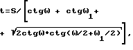
где S заданный шаг выступов;
ω и ω1 углы наклона боковых сторон треугольного профиля,
при этом величину подачи S0 инструмента выбирают равной шагу профиля, а направление подачи выбирают в сторону, противоположную режущей кромке, причем используют инструмент с главным φ и вспомогательным v1 углами в плане, равными соответственно углам наклона ω1 и ω боковых сторон треугольного профиля.7. A method of obtaining surfaces with alternating protrusions and depressions, according to which, with relative movement of the tool and the workpiece, they are cut with the cutting edge of the tool and the trimmed layer is plastically deformed, keeping it on the surface of the workpiece, characterized in that, when receiving protrusions and depressions of a triangular profile, the penetration depth t of the tool choose at least equal
where S is the given step of the protrusions;
ω and ω 1 the angles of inclination of the sides of the triangular profile,
the feed rate S 0 of the tool is chosen equal to the pitch of the profile, and the feed direction is selected in the direction opposite to the cutting edge, and a tool with the main φ and auxiliary v 1 angles in plan equal to the inclination angles ω 1 and ω of the sides of the triangular profile, respectively, is used.
t=0,29·S·ctg(β/2),
наружный диаметр D0 заготовки для получения резьбового профиля назначают по зависимости
Do=D-0,71·S·ctg(β/2),
где D заданный наружный диаметр по вершинам резьбового профиля,
а внутренний диаметр D2 заготовки для получения внутреннего резьбового профиля назначают по зависимости
D2=D1-0,59·S·ctg(β/2),
где D1 заданный диаметр резьбового профиля по его впадинам.18. A method of obtaining surfaces with alternating protrusions and depressions, according to which, with relative movement of the tool and the workpiece, the surface layer of the workpiece is cut with a tool having one straight cutting edge, and the trimmed layer is plastically deformed, characterized in that when receiving a triangular symmetrical threaded profile with step S and the angle β between the sides of the troughs for the internal thread profile, the depth t of the tool penetration is chosen at least equal to
t = 0.29 · S · ctg (β / 2),
the outer diameter D 0 of the workpiece to obtain a threaded profile is assigned according to
D o = D-0.71 · S · ctg (β / 2),
where D is the specified outer diameter at the vertices of the threaded profile,
and the inner diameter D 2 of the workpiece to obtain an internal threaded profile is assigned according to
D 2 = D 1 -0.59 · S · ctg (β / 2),
where D 1 a given diameter of the threaded profile along its hollows.
Priority Applications (8)
| Application Number | Priority Date | Filing Date | Title |
|---|---|---|---|
| RU9393017599A RU2044606C1 (en) | 1993-04-30 | 1993-04-30 | Method of obtaining surfaces with alternative projections and hollows (variants) and tool for its realization |
| AT94918624T ATE196270T1 (en) | 1993-04-30 | 1994-04-27 | METHOD FOR PRODUCING A SURFACE HAVING ALTERNATING HIGHNESS AND DEEPNESS AND TOOL FOR PERFORMING THE METHOD |
| DE69425899T DE69425899T2 (en) | 1993-04-30 | 1994-04-27 | METHOD FOR PRODUCING A SURFACE WITH ALTERNATING RISES AND DEPTHS, AND TOOL FOR IMPLEMENTING THE METHOD |
| EP94918624A EP0727269B1 (en) | 1993-04-30 | 1994-04-27 | Method of producing a surface with alternating ridges and depressions and a tool for carrying out the said method |
| ES94918624T ES2153423T3 (en) | 1993-04-30 | 1994-04-27 | METHOD TO PRODUCE A SURFACE WITH NERVES AND ALTERNATE DEPRESSIONS AND TOOL TO CARRY OUT THAT METHOD. |
| UA95104430A UA41922C2 (en) | 1993-04-30 | 1994-04-27 | Method and TOOL of obtaining the surfaces with alternating protrusions and cavities (variants) |
| US08/545,640 US5775187A (en) | 1993-04-30 | 1994-04-27 | Method and apparatus of producing a surface with alternating ridges and depressions |
| PCT/RU1994/000121 WO1994025217A2 (en) | 1993-04-30 | 1994-04-27 | Method of producing a surface with alternating ridges and depressions and a tool for carrying out the said method |
Applications Claiming Priority (1)
| Application Number | Priority Date | Filing Date | Title |
|---|---|---|---|
| RU9393017599A RU2044606C1 (en) | 1993-04-30 | 1993-04-30 | Method of obtaining surfaces with alternative projections and hollows (variants) and tool for its realization |
Publications (2)
| Publication Number | Publication Date |
|---|---|
| RU2044606C1 true RU2044606C1 (en) | 1995-09-27 |
| RU93017599A RU93017599A (en) | 1997-03-20 |
Family
ID=20139778
Family Applications (1)
| Application Number | Title | Priority Date | Filing Date |
|---|---|---|---|
| RU9393017599A RU2044606C1 (en) | 1993-04-30 | 1993-04-30 | Method of obtaining surfaces with alternative projections and hollows (variants) and tool for its realization |
Country Status (8)
| Country | Link |
|---|---|
| US (1) | US5775187A (en) |
| EP (1) | EP0727269B1 (en) |
| AT (1) | ATE196270T1 (en) |
| DE (1) | DE69425899T2 (en) |
| ES (1) | ES2153423T3 (en) |
| RU (1) | RU2044606C1 (en) |
| UA (1) | UA41922C2 (en) |
| WO (1) | WO1994025217A2 (en) |
Cited By (6)
| Publication number | Priority date | Publication date | Assignee | Title |
|---|---|---|---|---|
| RU2228448C2 (en) * | 2002-03-22 | 2004-05-10 | Открытое акционерное общество "АВТОВАЗ" | Muffler (versions) and method of manufacture of noise-damping member |
| RU2391197C2 (en) * | 2008-05-20 | 2010-06-10 | Государственное образовательное учреждение высшего профессионального образования "Уфимский государственный авиационный технический университет" | Method to form heat exchange surface |
| RU2493527C1 (en) * | 2009-06-08 | 2013-09-20 | Кабусики Кайся Кобе Сейко Се | Metal plate for heat exchange and metal plate manufacturing method |
| RU2505760C2 (en) * | 2008-09-09 | 2014-01-27 | Конинклейке Филипс Электроникс, Н.В. | Heat exchanger with horizontal finning for cryogenic cooling with repeated condensation |
| RU2556897C1 (en) * | 2014-01-21 | 2015-07-20 | Николай Николаевич Зубков | Surface hardening by cutting-forming tool |
| RU2638233C1 (en) * | 2017-01-23 | 2017-12-12 | Государственное научное учреждение "Институт порошковой металлургии" | Method for manufacturing thermal pipe with aluminium housing and water as heat carrier |
Families Citing this family (24)
| Publication number | Priority date | Publication date | Assignee | Title |
|---|---|---|---|---|
| DE19608824A1 (en) * | 1996-03-07 | 1997-09-18 | Inst Mikrotechnik Mainz Gmbh | Process for the production of micro heat exchangers |
| DE19721692C2 (en) * | 1997-05-23 | 2000-02-24 | Freudenberg Carl Fa | Sealing arrangement |
| JPH11311256A (en) * | 1998-04-24 | 1999-11-09 | Nippon Seiko Kk | Shock absorbing steering shaft |
| US7311137B2 (en) * | 2002-06-10 | 2007-12-25 | Wolverine Tube, Inc. | Heat transfer tube including enhanced heat transfer surfaces |
| DE60317506T2 (en) * | 2002-06-10 | 2008-09-18 | Wolverine Tube Inc. | HEAT EXCHANGE TUBE AND METHOD AND TOOL FOR THE PRODUCTION THEREOF |
| US8573022B2 (en) * | 2002-06-10 | 2013-11-05 | Wieland-Werke Ag | Method for making enhanced heat transfer surfaces |
| US20060112535A1 (en) | 2004-05-13 | 2006-06-01 | Petur Thors | Retractable finning tool and method of using |
| US10155268B2 (en) * | 2005-03-11 | 2018-12-18 | Nissan Motor Co., Ltd. | Cutting edge configuration of cutting tool |
| PT1866119E (en) * | 2005-03-25 | 2012-07-05 | Wolverine Tube Inc | Tool for making enhanced heat transfer surfaces |
| CN101287955B (en) * | 2005-06-07 | 2010-09-29 | 沃尔弗林管子公司 | Heat Transfer Interface for Electronics Cooling |
| US20070251602A1 (en) | 2005-11-10 | 2007-11-01 | Gagnon Paul J Jr | Brazing material with continuous length layer of elastomer containing a flux |
| US20110079376A1 (en) * | 2009-10-03 | 2011-04-07 | Wolverine Tube, Inc. | Cold plate with pins |
| US20120026692A1 (en) * | 2010-07-28 | 2012-02-02 | Wolverine Tube, Inc. | Electronics substrate with enhanced direct bonded metal |
| US9795057B2 (en) | 2010-07-28 | 2017-10-17 | Wolverine Tube, Inc. | Method of producing a liquid cooled coldplate |
| US9681580B2 (en) * | 2010-07-28 | 2017-06-13 | Wolverine Tube, Inc. | Method of producing an enhanced base plate |
| US10531594B2 (en) * | 2010-07-28 | 2020-01-07 | Wieland Microcool, Llc | Method of producing a liquid cooled coldplate |
| US9733024B2 (en) * | 2012-11-30 | 2017-08-15 | Carlos Quesada Saborio | Tubing element with fins for a heat exchanger |
| CN103586496B (en) * | 2013-10-31 | 2016-05-04 | 中国船舶重工集团公司第七0七研究所 | A kind of dedicated tool of processing conical boss |
| WO2015112771A2 (en) * | 2014-01-22 | 2015-07-30 | Wolverine Tube, Inc. | Double-sided micro fin plate for plate heat exchanger |
| EP3295777A4 (en) | 2015-05-15 | 2019-01-23 | Wolverine Tube, Inc. | Liquid cooled coldplate |
| DE102015220674A1 (en) * | 2015-10-22 | 2017-04-27 | Zf Friedrichshafen Ag | Running drum of a tire, wheel and / or chassis test stand |
| EP3388682B1 (en) * | 2017-04-12 | 2021-11-17 | Pfeiffer Vacuum Gmbh | Vacuum pump with a heat sink and method for manufacturing the heat sink |
| US12098893B2 (en) | 2020-08-10 | 2024-09-24 | Ge Aviation Systems Limited | Topological heatsink |
| US20230108259A1 (en) * | 2021-10-05 | 2023-04-06 | Delavan Inc. | Threaded joints for fluid injection components |
Family Cites Families (19)
| Publication number | Priority date | Publication date | Assignee | Title |
|---|---|---|---|---|
| SU63550A1 (en) * | 1939-04-22 | 1943-11-30 | В.М. Серебряков | Cutter |
| US3791003A (en) * | 1970-02-24 | 1974-02-12 | Peerless Of America | Method of frabricating a plural finned heat exchanger |
| US3665573A (en) * | 1970-05-18 | 1972-05-30 | Atomic Energy Commission | Method of fabricating a heat pipe |
| US3781959A (en) * | 1970-09-02 | 1974-01-01 | Peerless Of America | Method of fabricating a finned heat exchanger tube |
| US3866286A (en) * | 1973-07-02 | 1975-02-18 | Peerless Of America | Method of making a finned tube heat exchanger having a circular cross section |
| US3947941A (en) * | 1975-01-14 | 1976-04-06 | Peerless Of America, Incorporated | Method of making a heat exchanger |
| US4936719A (en) * | 1976-08-24 | 1990-06-26 | Greenleaf Corporation | Cutter and indexable on edge inserts with aligned corners and staggered serrated edges |
| SU910365A1 (en) * | 1979-10-22 | 1982-03-07 | Всесоюзный заочный машиностроительный институт | Method of cutting by self-rotating multiblade tool |
| SU1301567A1 (en) * | 1985-08-14 | 1987-04-07 | Предприятие П/Я А-1872 | Cutting tool |
| SU1662766A1 (en) * | 1986-07-03 | 1991-07-15 | Белорусский Политехнический Институт | Tool for making finned tube radiators |
| SU1683869A1 (en) * | 1986-07-25 | 1991-10-15 | Белорусский Политехнический Институт | Machine for manufacture of flat ribber heat exchangers |
| US4854785A (en) * | 1987-08-17 | 1989-08-08 | Gte Valenite Corporation | Scalloped threader cutting insert |
| SU1558556A1 (en) * | 1988-02-15 | 1990-04-23 | Мгту Им.Н.Э.Баумана | Method of producing capillary porous structure of heat tube |
| SU1625586A1 (en) * | 1989-02-17 | 1991-02-07 | Предприятие П/Я А-1067 | Device for breaking chip during lathing plastic materials |
| SU1764834A1 (en) * | 1989-02-28 | 1992-09-30 | Предприятие П/Я Р-6601 | Tool for making ribbed tubular radiators |
| SU1764835A1 (en) * | 1989-02-28 | 1992-09-30 | Предприятие П/Я Р-6601 | Tool for making ribbed tubular radiators |
| US5059069A (en) * | 1990-02-09 | 1991-10-22 | Sandvik Ab | Insert for thread cutting |
| DE4119162C1 (en) * | 1991-06-11 | 1992-05-21 | Gebr. Heller Maschinenfabrik Gmbh, 7440 Nuertingen, De | |
| DE4137467A1 (en) * | 1991-11-14 | 1993-05-19 | Neumo Grundbesitz Gmbh | PROFILE CUTTING TOOL, ESPECIALLY THREAD MILLING |
-
1993
- 1993-04-30 RU RU9393017599A patent/RU2044606C1/en active
-
1994
- 1994-04-27 EP EP94918624A patent/EP0727269B1/en not_active Expired - Lifetime
- 1994-04-27 ES ES94918624T patent/ES2153423T3/en not_active Expired - Lifetime
- 1994-04-27 US US08/545,640 patent/US5775187A/en not_active Expired - Fee Related
- 1994-04-27 AT AT94918624T patent/ATE196270T1/en not_active IP Right Cessation
- 1994-04-27 WO PCT/RU1994/000121 patent/WO1994025217A2/en not_active Ceased
- 1994-04-27 UA UA95104430A patent/UA41922C2/en unknown
- 1994-04-27 DE DE69425899T patent/DE69425899T2/en not_active Expired - Lifetime
Non-Patent Citations (1)
| Title |
|---|
| Авторское свидетельство СССР N 1558556, кл. B 23B 1/00, 1988. * |
Cited By (6)
| Publication number | Priority date | Publication date | Assignee | Title |
|---|---|---|---|---|
| RU2228448C2 (en) * | 2002-03-22 | 2004-05-10 | Открытое акционерное общество "АВТОВАЗ" | Muffler (versions) and method of manufacture of noise-damping member |
| RU2391197C2 (en) * | 2008-05-20 | 2010-06-10 | Государственное образовательное учреждение высшего профессионального образования "Уфимский государственный авиационный технический университет" | Method to form heat exchange surface |
| RU2505760C2 (en) * | 2008-09-09 | 2014-01-27 | Конинклейке Филипс Электроникс, Н.В. | Heat exchanger with horizontal finning for cryogenic cooling with repeated condensation |
| RU2493527C1 (en) * | 2009-06-08 | 2013-09-20 | Кабусики Кайся Кобе Сейко Се | Metal plate for heat exchange and metal plate manufacturing method |
| RU2556897C1 (en) * | 2014-01-21 | 2015-07-20 | Николай Николаевич Зубков | Surface hardening by cutting-forming tool |
| RU2638233C1 (en) * | 2017-01-23 | 2017-12-12 | Государственное научное учреждение "Институт порошковой металлургии" | Method for manufacturing thermal pipe with aluminium housing and water as heat carrier |
Also Published As
| Publication number | Publication date |
|---|---|
| ATE196270T1 (en) | 2000-09-15 |
| US5775187A (en) | 1998-07-07 |
| EP0727269A4 (en) | 1998-02-25 |
| WO1994025217A3 (en) | 1994-12-22 |
| WO1994025217A2 (en) | 1994-11-10 |
| ES2153423T3 (en) | 2001-03-01 |
| DE69425899D1 (en) | 2000-10-19 |
| DE69425899T2 (en) | 2001-04-12 |
| EP0727269A1 (en) | 1996-08-21 |
| UA41922C2 (en) | 2001-10-15 |
| EP0727269B1 (en) | 2000-09-13 |
Similar Documents
| Publication | Publication Date | Title |
|---|---|---|
| RU2044606C1 (en) | Method of obtaining surfaces with alternative projections and hollows (variants) and tool for its realization | |
| JP4278514B2 (en) | Improved centrifugal cast tube and related manufacturing method and apparatus | |
| US5152060A (en) | Process for manufacturing fine-structured bodies | |
| US5249359A (en) | Process for manufacturing finely structured bodies such as heat exchangers | |
| JP6603955B2 (en) | Throwaway tip | |
| US5503506A (en) | High precision, high surface finish broaching tool | |
| US5682946A (en) | Tube for use in a heat exchanger | |
| US8573022B2 (en) | Method for making enhanced heat transfer surfaces | |
| US4395303A (en) | Method of manufacturing thin-walled corrosion resistant metallic objects | |
| US4577381A (en) | Boiling heat transfer pipes | |
| US6687995B1 (en) | Heat exchanger and method for producing a heat exchanger | |
| US7311137B2 (en) | Heat transfer tube including enhanced heat transfer surfaces | |
| JP2003185386A (en) | Heat-exchanger tube structured on both sides and method for its manufacture | |
| CA1316908C (en) | High performance heat transfer tube for heat exchanger | |
| CN1087162A (en) | Internally ribbed heat transfer tube | |
| US4672834A (en) | Method for making extended heat transfer surfaces and a tool for putting said method into practice | |
| CA2543480C (en) | Method and tool for making enhanced heat transfer surfaces | |
| US4541261A (en) | Method of producing heat pipe | |
| JPS6011800B2 (en) | Manufacturing method for condensing heat exchanger tubes | |
| Prasad et al. | Machining performance of protruded textured high-speed steel cutting tool under dry turning operation | |
| DE1927184A1 (en) | Heat exchanger | |
| Kukowski | Mdt: Micro deformation technology | |
| Zubkov | Innovation method in enhancing the internal surface of a heat exchange tube | |
| JP3069277B2 (en) | Heat transfer tube with inner groove and method of manufacturing the same | |
| JPH09292062A (en) | Inner grooved tube with excellent corrosion resistance |