RU195209U1 - GAS FLOW SAMPLING FLOW NORMALIZING - Google Patents
GAS FLOW SAMPLING FLOW NORMALIZING Download PDFInfo
- Publication number
- RU195209U1 RU195209U1 RU2018142152U RU2018142152U RU195209U1 RU 195209 U1 RU195209 U1 RU 195209U1 RU 2018142152 U RU2018142152 U RU 2018142152U RU 2018142152 U RU2018142152 U RU 2018142152U RU 195209 U1 RU195209 U1 RU 195209U1
- Authority
- RU
- Russia
- Prior art keywords
- gas
- pressure
- temperature
- sampling
- measuring
- Prior art date
Links
- 238000005070 sampling Methods 0.000 title claims abstract description 34
- 229910001220 stainless steel Inorganic materials 0.000 claims description 2
- 239000010935 stainless steel Substances 0.000 claims description 2
- 239000007789 gas Substances 0.000 abstract description 54
- VNWKTOKETHGBQD-UHFFFAOYSA-N methane Chemical compound C VNWKTOKETHGBQD-UHFFFAOYSA-N 0.000 abstract description 10
- 238000013461 design Methods 0.000 abstract description 6
- 238000009434 installation Methods 0.000 abstract description 6
- 239000003345 natural gas Substances 0.000 abstract description 5
- 238000010438 heat treatment Methods 0.000 abstract description 3
- 238000010521 absorption reaction Methods 0.000 abstract description 2
- 230000005540 biological transmission Effects 0.000 abstract description 2
- 238000004140 cleaning Methods 0.000 abstract description 2
- 238000011161 development Methods 0.000 abstract description 2
- 238000000605 extraction Methods 0.000 abstract description 2
- 238000004519 manufacturing process Methods 0.000 abstract description 2
- 238000012545 processing Methods 0.000 abstract description 2
- 238000010276 construction Methods 0.000 abstract 1
- 239000000523 sample Substances 0.000 description 11
- 238000000034 method Methods 0.000 description 4
- 239000003638 chemical reducing agent Substances 0.000 description 3
- 239000007788 liquid Substances 0.000 description 3
- 230000006978 adaptation Effects 0.000 description 2
- 230000015572 biosynthetic process Effects 0.000 description 2
- 239000000428 dust Substances 0.000 description 2
- 239000002360 explosive Substances 0.000 description 2
- 238000012544 monitoring process Methods 0.000 description 2
- 239000002245 particle Substances 0.000 description 2
- 238000003466 welding Methods 0.000 description 2
- 239000002775 capsule Substances 0.000 description 1
- 230000003749 cleanliness Effects 0.000 description 1
- 210000001520 comb Anatomy 0.000 description 1
- 238000009833 condensation Methods 0.000 description 1
- 230000005494 condensation Effects 0.000 description 1
- 238000005553 drilling Methods 0.000 description 1
- 239000012530 fluid Substances 0.000 description 1
- 231100001261 hazardous Toxicity 0.000 description 1
- 238000009413 insulation Methods 0.000 description 1
- 230000003189 isokinetic effect Effects 0.000 description 1
- 238000012423 maintenance Methods 0.000 description 1
- 239000002184 metal Substances 0.000 description 1
- 238000010606 normalization Methods 0.000 description 1
- -1 nuclear Substances 0.000 description 1
- 238000011084 recovery Methods 0.000 description 1
- 238000012216 screening Methods 0.000 description 1
- 239000007787 solid Substances 0.000 description 1
- 230000006641 stabilisation Effects 0.000 description 1
- 238000011105 stabilization Methods 0.000 description 1
- 239000003351 stiffener Substances 0.000 description 1
- 239000000126 substance Substances 0.000 description 1
Images


Classifications
-
- G—PHYSICS
- G01—MEASURING; TESTING
- G01N—INVESTIGATING OR ANALYSING MATERIALS BY DETERMINING THEIR CHEMICAL OR PHYSICAL PROPERTIES
- G01N1/00—Sampling; Preparing specimens for investigation
- G01N1/02—Devices for withdrawing samples
- G01N1/22—Devices for withdrawing samples in the gaseous state
Landscapes
- Health & Medical Sciences (AREA)
- Life Sciences & Earth Sciences (AREA)
- Engineering & Computer Science (AREA)
- Biomedical Technology (AREA)
- Molecular Biology (AREA)
- Physics & Mathematics (AREA)
- Chemical & Material Sciences (AREA)
- Analytical Chemistry (AREA)
- Biochemistry (AREA)
- General Health & Medical Sciences (AREA)
- General Physics & Mathematics (AREA)
- Immunology (AREA)
- Pathology (AREA)
- Sampling And Sample Adjustment (AREA)
Abstract
Полезная модель относится к устройствам, применяемым в системе магистрального транспорта газа, а также предприятиях добычи и переработки газа и может быть применено для отбора газа из магистрального трубопровода диаметром от 200 мм до 1440 мм при давлении до 12 МПа, его нормализации до температуры в точке отбора и подаче в измерительную камеру к средству измерения таких технологических параметров как содержание влаги, давление, температура, молекулярная плотность и др.Технической задачей и положительным результатом заявляемого изобретения является разработка нового устройства отбора пробы природного газа проточного типа, для применения на магистральных газопроводах и технологических установках компрессорных и газоизмерительных станций, других объектах магистрального газопровода с давлением транспортируемой среды до 12 МПа, максимально простой конструкции и не нуждающееся в дополнительном обеспечении техническими средствами для очистки и подогрева отбираемой пробы газа.Технический результат достигается за счет конструктивного исполнения устройства в виде теплового насоса, предназначенного для монтажа непосредственно в трубопровод путем установки на фланец. Принцип действия устройства следующий:- проба, под действием давления в трубопроводе, поступает через редуцирующий дроссель в импульсную трубку, сообщающуюся с измерительной камерой, находящейся под атмосферным давлением;- проходя по импульсной трубке редуцированный (до давления, близкого к атмосферному) и охлажденный газ восстанавливает свою температуру до температуры в точке отбора;- восстановленный до исходной температуры газ с давлением, близким к атмосферному, поступает в измерительную камеру, куда подключается средство измерения влажности, температуры или другой физической величины;- газ проходит через камеру поточно и по импульсной трубке стравливается в атмосферу или в поглотительную линию.The utility model relates to devices used in the gas transmission system, as well as gas production and processing enterprises, and can be used to take gas from a gas pipeline with a diameter of 200 mm to 1440 mm at a pressure of up to 12 MPa, normalize it to a temperature at the point of extraction and feeding into the measuring chamber to the means of measuring such technological parameters as moisture content, pressure, temperature, molecular density, etc. The technical task and the positive result of the claimed invention is the development of a new flow-type natural gas sampling device, for use on gas pipelines and technological installations of compressor and gas measuring stations, other gas pipeline facilities with a transported medium pressure of up to 12 MPa, of the simplest possible construction and not requiring additional technical means for cleaning and heating the sampled gas. The technical result is achieved due to the design of the device in the form of heat a pump designed to be mounted directly in a pipeline by mounting flange. The principle of operation of the device is as follows: - a sample, under the influence of pressure in the pipeline, enters through a reducing throttle into a pulse tube communicating with a measuring chamber under atmospheric pressure; - passing through a pulse tube reduces (to a pressure close to atmospheric pressure) and the cooled gas restores its temperature to the temperature at the sampling point; - the gas restored to the initial temperature with a pressure close to atmospheric pressure enters the measuring chamber, where the measuring instrument is connected humidity, temperature or other physical quantities; - gas passes through the chamber and the thread on the control line vented to the atmosphere or to the absorption line.
Description
Полезная модель относится к устройствам, применяемым в системе магистрального транспорта газа, а также предприятиях добычи и переработки газа и может быть применено для отбора газа из магистрального трубопровода диаметром от 200 мм до 1440 мм при давлении до 12 МПа, его нормализации до температуры в точке отбора и подаче в измерительную камеру к средству измерения таких технологических параметров как содержание влаги, давление, температура, молекулярная плотность и др.The utility model relates to devices used in the gas transmission system, as well as gas production and processing enterprises, and can be used to take gas from a gas pipeline with a diameter of 200 mm to 1440 mm at a pressure of up to 12 MPa, normalize it to a temperature at the point of extraction and feeding into the measuring chamber to the means of measuring such technological parameters as moisture content, pressure, temperature, molecular density, etc.
Устройство представляет собой конструкцию, изготовленную из металла, имеющее габариты, позволяющие производить отбор газа из срединной области (вторая треть по поперечному сечению) сечения газопроводов указанных диаметров, и подавать его в измерительную камеру по импульсной трубке. Во время прохождения газа по импульсной трубке, газ восстанавливает начальную температуру в точке отбора за счет теплового обмена со стенкой импульсной трубки, при этом конструкция устройства подобна тепловому насосу и обеспечивает теплообмен трубки с окружающей средой.The device is a structure made of metal with dimensions that allow gas to be taken from the middle region (second third of the cross section) of the cross section of gas pipelines of the indicated diameters, and to supply it to the measuring chamber via a pulse tube. During the passage of gas through the pulse tube, the gas restores the initial temperature at the sampling point due to heat exchange with the wall of the pulse tube, while the design of the device is similar to a heat pump and provides heat exchange between the tube and the environment.
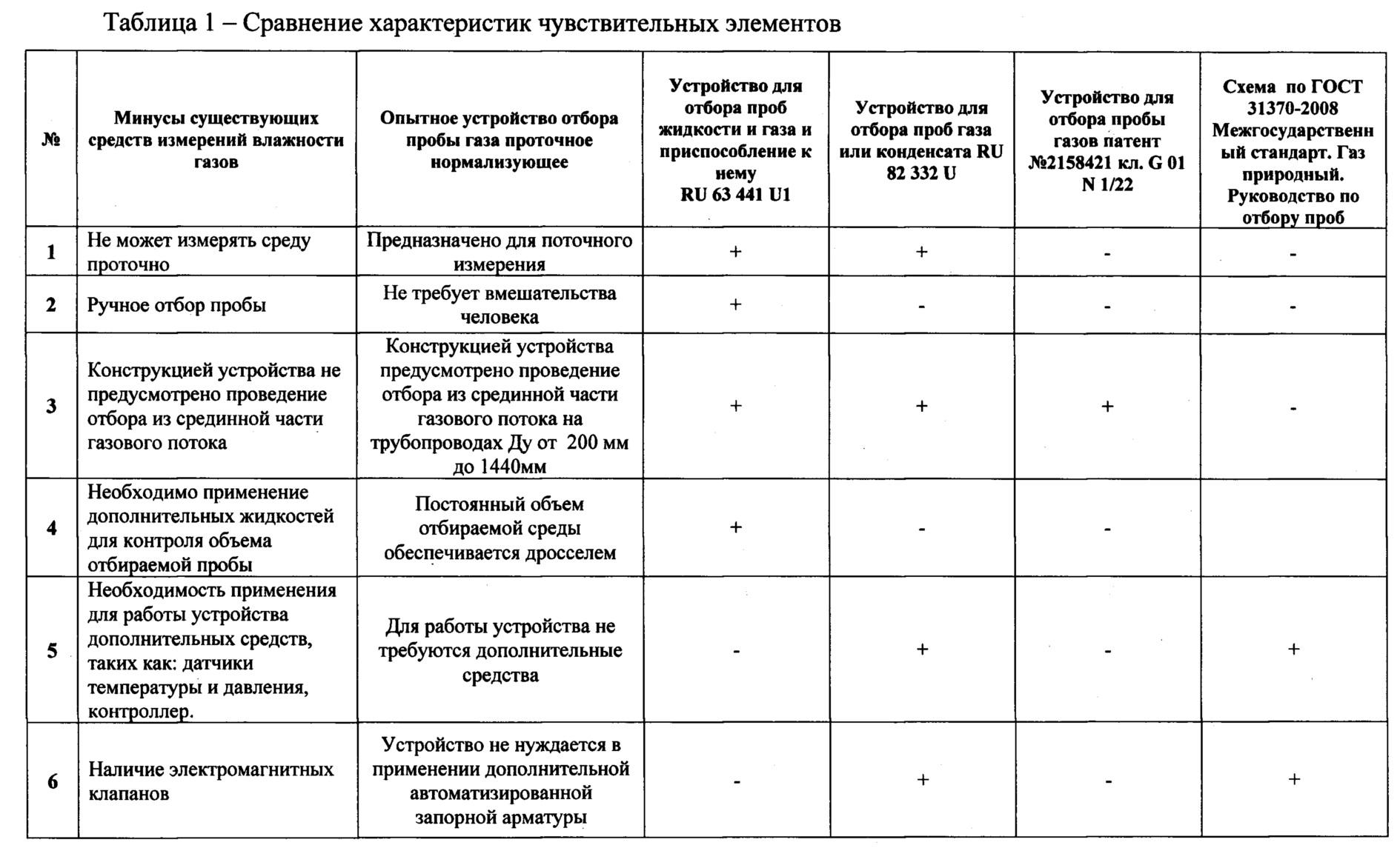
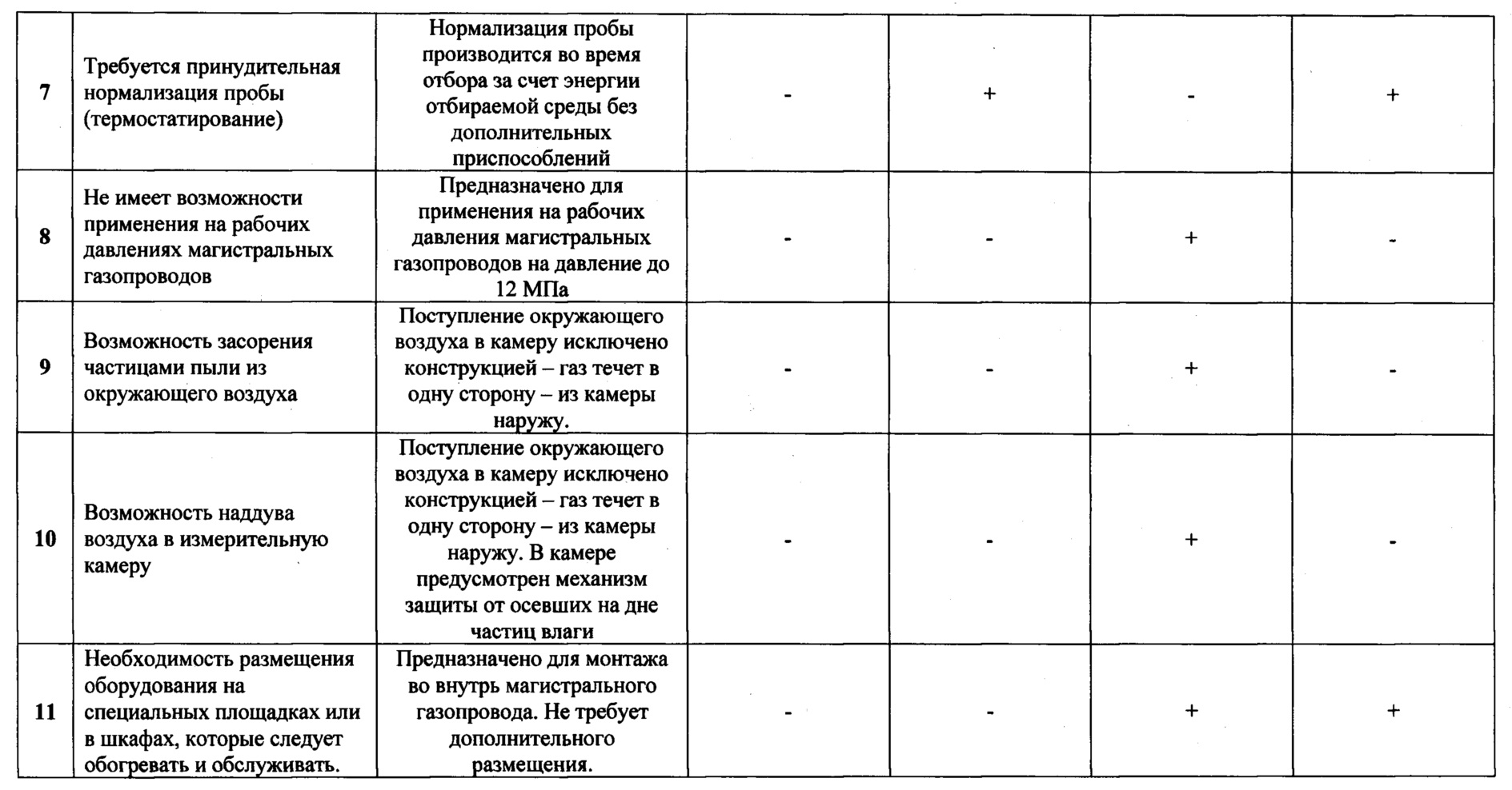
На сегодняшний день науке известны следующие технические решения, сводная информация о которых приведена в таблице 1:To date, science knows the following technical solutions, a summary of which is given in table 1:
1. Известно устройство для отбора проб жидкости и газа и приспособление к нему [RU 63 441 U1]. Полезная модель относится к отбору проб пластовой жидкости и газа при бурении нефтяных и газовых скважин. Устройство представляет собой цилиндрический корпус со средоразделителем в виде поршня внутри и с присоединенными с обоих концов крышками, причем непосредственно на каждой крышке расположено по одному игольчатому вентилю. Приспособление для ПЖУ, включает тройник, вентиль высокого давления и соединительные элементы.1. A device for sampling liquid and gas and adaptation to it [RU 63 441 U1]. The utility model relates to sampling of formation fluid and gas while drilling oil and gas wells. The device is a cylindrical body with a medium separator in the form of a piston inside and with covers attached at both ends, and one needle valve is located directly on each cover. The device for PZhU includes a tee, a high pressure valve and connecting elements.
Недостаток известного решения заключается в:A disadvantage of the known solution is:
- принципе отбора пробы порцией, т.е. после забора пробы до ее высвобождения повторно устройство использовать невозможно;- the principle of sampling in portions, i.e. after taking a sample before releasing it, the device cannot be reused;
- невозможности производить отбор из срединной части трубопровода;- the inability to make a selection from the middle of the pipeline;
- необходимость применения дополнительных жидкостей для контроля объема отбираемой пробы.- the need to use additional liquids to control the volume of the sample taken.
2. Известно устройство для отбора проб газа или конденсата [RU 82 332 U]. Полезная модель относится к устройствам для отбора проб газа или конденсата (пробоотборным устройствам) и может быть использована в нефтяной и газовой промышленности при отборе проб газа или конденсата с частой периодичностью или при одновременном отборе нескольких проб.2. A device for sampling gas or condensate [RU 82 332 U] is known. The utility model relates to gas or condensate sampling devices (sampling devices) and can be used in the oil and gas industry to take gas or condensate samples at frequent intervals or when several samples are taken simultaneously.
Недостаток известного решения заключается в:A disadvantage of the known solution is:
- принципе отбора пробы порцией, т.е. после забора пробы до ее высвобождения повторно устройство использовать невозможно;- the principle of sampling in portions, i.e. after taking a sample before releasing it, the device cannot be reused;
- невозможности производить отбор из срединной части трубопровода;- the inability to make a selection from the middle of the pipeline;
- необходимости применения датчиков температуры, давления и контроллера для обеспечения работы устройства;- the need to use temperature, pressure and controller sensors to ensure the operation of the device;
- наличие электромагнитных клапанов в составе устройства, усложняющих конструкцию и эксплуатацию, а также требующих внешнего электрического питания и коммутационной аппаратуры;- the presence of electromagnetic valves in the device, complicating the design and operation, as well as requiring external electrical power and switching equipment;
- потребность в принудительном термостатировании капсул газом.- the need for forced temperature control of the capsules with gas.
3. Также известно устройство для отбора пробы газов [патент №2158421 кл. G 01N 1/22, 1999 г.] для контроля чистоты воздуха низкого давления, содержащее зонд, пробоотборную трубку, коническую камеру и анализатор пробы.3. Also known is a device for sampling gases [patent No. 2158421 class.
Недостатком этого пробоотборного устройства является невозможность применения на рабочих давлениях магистральных газопроводов до 12 МПа (устройство применимо на низких давлениях до 0,1 МПа); возможность наддува воздуха в коническую камеру через открытую ее часть в случае возникновения сильных ветровых потоков в атмосфере и нарушение стационарности течения газовой среды, что приводит к резкому снижению изокинетичности пробоотбора и его представительности. Кроме того, частицы пыли могут через коническую камеру засасываться в пробоотборный патрубок и попадать в измерительную камеру анализатора.The disadvantage of this sampling device is the impossibility of using gas pipelines up to 12 MPa at operating pressures (the device is applicable at low pressures up to 0.1 MPa); the ability to pressurize air into the conical chamber through its open part in the event of strong wind flows in the atmosphere and a violation of the stationary flow of the gas medium, which leads to a sharp decrease in the isokinetics of sampling and its representativeness. In addition, dust particles can be sucked into the sampling pipe through a conical chamber and enter the analyzer’s measuring chamber.
4. Также известно устройство для отбора проб газов [патент RU 60724 U1 от 26.09.2006], содержащее зонд, отборную трубку, запорный элемент, коническую камеру с установленным в ней с возможностью перемещения пробозаборным патрубком, и анализатор, соединенный с пробозаборным патрубком. Устройство относится к технике пробоотбора и контроля содержания механических примесей в воздухе и газовых средах и может быть использовано для мониторинга чистоты газов, транспортируемых по магистральным трубопроводам потребителю, в ракетно-космической, газовой, атомной, химической и в других отраслях промышленности.4. It is also known a device for sampling gases [patent RU 60724 U1 of 09.26.2006], containing a probe, a sampling tube, a locking element, a conical chamber with a sampling port installed therein with the possibility of movement, and an analyzer connected to the sampling port. The device relates to techniques for sampling and monitoring the content of solids in air and gas environments and can be used to monitor the purity of gases transported through main pipelines to the consumer, in space rocket, gas, nuclear, chemical and other industries.
Недостатком указанного изобретения является, невозможность применения для взрывопожароопасных газов, а также при рабочих давлениях магистральных газопроводов (до 12 МПа), отсутствие измерительной камеры для монтажа средств измерения.The disadvantage of this invention is the impossibility of use for explosive and fire hazardous gases, as well as at operating pressures of gas pipelines (up to 12 MPa), the absence of a measuring chamber for mounting measuring instruments.
5. Наиболее близким к предлагаемому техническому решению является схема прямого непрерывного отбора проб с применением редуктора давления [ГОСТ 31370-2008 Межгосударственный стандарт. Газ природный. Руководство по отбору проб]. Схема предназначена для прямого непрерывного отбора проб, в том числе из среды природного газа.5. The closest to the proposed technical solution is a direct continuous sampling scheme using a pressure reducer [GOST 31370-2008 Interstate Standard. Natural gas. Sampling Guide]. The scheme is intended for direct continuous sampling, including from natural gas.
В состав указанной схемы входят клапан сброса давления, обогреваемая камера, электронагреватель, термоизоляция, компрессор, шаровой вентиль, пламегаситель, индикатор температуры, ротаметр, аналитический блок, сигнализатор взрывоопасных концентраций, фильтр пыли, редуктор с регулятором давления и запорная арматура.The structure of the indicated circuit includes a pressure relief valve, a heated chamber, an electric heater, thermal insulation, a compressor, a ball valve, a flame arrester, a temperature indicator, a rotameter, an analytical unit, an explosive concentration indicator, a dust filter, a reducer with a pressure regulator and shutoff valves.
Минусами приведённой выше схемы является большое количество элементов необходимых для обеспечения ее работы, сложность конструкции и процедуры обслуживания и наличие сопутствующих затрат на обогрев импульсных линий, редуктора, запорной арматуры и другого оборудования; необходимость проведения отборов в лабораторном помещении.The disadvantages of the above scheme is the large number of elements necessary to ensure its operation, the complexity of the design and maintenance procedures, and the attendant costs for heating impulse lines, gearboxes, valves, and other equipment; the need for screening in a laboratory room.
Технической задачей и положительным результатом заявляемого изобретения является разработка нового устройства отбора пробы природного газа проточного типа (фиг. 1), для применения на магистральных газопроводах и технологических установках компрессорных и газоизмерительных станций, других объектах магистрального газопровода с давлением транспортируемой среды до 12 МПа, максимально простой конструкции и не нуждающееся в дополнительном обеспечении техническими средствами для очистки и подогрева отбираемой пробы газа.The technical task and the positive result of the claimed invention is the development of a new flow-type natural gas sampling device (Fig. 1), for use on gas pipelines and process plants of compressor and gas measuring stations, other gas pipeline facilities with a transported medium pressure of up to 12 MPa, as simple as possible designs and not requiring additional provision with technical means for cleaning and heating the gas sample taken.
Технический результат достигается за счет конструктивного исполнения устройства (фиг. 1) в виде теплового насоса, предназначенного для монтажа непосредственно в трубопровод путем установки на фланец. Установка в трубопровод производиться путем зажима монтажной пластины (фиг. 2, сн. 5) между двумя фланцами. Принцип действия устройства следующий:The technical result is achieved due to the design of the device (Fig. 1) in the form of a heat pump intended for installation directly in the pipeline by mounting on a flange. Installation in the pipeline is done by clamping the mounting plate (Fig. 2, sn. 5) between the two flanges. The principle of operation of the device is as follows:
- проба, под действием давления в трубопроводе, поступает через редуцирующий дроссель (фиг. 2, сн. 1) в импульсную трубку (фиг. 2, сн. 2; фиг. 5, сн. 2), сообщающуюся с измерительной камерой (фиг. 2, сн. 6), находящейся под атмосферным давлением;- the sample, under the action of pressure in the pipeline, enters through a reducing throttle (Fig. 2, sn. 1) into a pulse tube (Fig. 2, sn. 2; Fig. 5, sn. 2), communicating with the measuring chamber (Fig. 2, d. 6), which is under atmospheric pressure;
- проходя по импульсной трубке редуцированный (до давления близкого к атмосферному) и охлажденный газ восстанавливает свою температуру до температуры в точке отбора;- passing through a pulse tube, the reduced (to a pressure close to atmospheric) and cooled gas restores its temperature to the temperature at the sampling point;
- восстановленный до исходной температуры газ с давлением, близким к атмосферному, поступает в измерительную камеру (фиг. 3), куда подключается через резьбовое соединение (фиг. 3, сн. 12) средство измерения влажности, температуры или другой физической величины;- the gas recovered to the initial temperature with a pressure close to atmospheric pressure enters the measuring chamber (Fig. 3), where it is connected via a threaded connection (Fig. 3, sn. 12) with a means of measuring humidity, temperature or other physical quantity;
- газ проходит через отверстия в камере (фиг. 3, сн. 13, сн. 14) поточно, и по импульсной трубке стравливается в атмосферу или в поглотительную линию (фиг. 5, сн. 8);- the gas passes through the holes in the chamber (Fig. 3, sn. 13, sn. 14) in-line, and is discharged through an impulse tube into the atmosphere or into an absorption line (Fig. 5, sn. 8);
Восстановление температуры газа обеспечивается за счет внутренней поверхности импульсной трубки (фиг. 2, сн. 2) и наружной поверхности теплообменных гребней (фиг. 2, сн. 3; фиг. 6, сн. 11)Gas temperature recovery is provided due to the inner surface of the impulse tube (Fig. 2, sn. 2) and the outer surface of the heat exchange ridges (Fig. 2, sn. 3; Fig. 6, sn. 11)
Для подключения дросселя применяется внутренняя резьба в импульсной трубке. Для защиты дросселя от засорения место установки (фиг. 2, сн. 1) оснащается дополнительными юбками, отводящими механические частицы в стороны - по потоку движения газа.To connect the throttle, an internal thread in the impulse tube is used. To protect the throttle against clogging, the installation site (Fig. 2, sn. 1) is equipped with additional skirts that divert mechanical particles to the sides - along the gas flow.
Импульсная трубка по всей длине имеет двухсторонний сварной шов с теплообменными гребнями. Трубка в плоскости гребня уложена таким образом, чтобы при образовании конденсата на отключенном устройстве он мог стечь в нижнюю точку. Дроссель вкручивается в трубку под углом к горизонту для обеспечения слива конденсата из нижней точки.The impulse tube along the entire length has a double-sided weld with heat-exchange combs. The tube in the ridge plane is laid in such a way that when condensation forms on the disconnected device, it can drain to a lower point. The throttle is screwed into the tube at an angle to the horizontal to allow condensate to drain from the bottom.
Длина импульсной трубки и наружная площадь теплообменных гребней подобрана таким образом, чтобы обеспечивать восстановление температуры редуцированного газа до исходной при перепаде давления на дросселе до 12 МПа (относительно близкого к атмосферному во внутренней полости импульсной трубки). Для обеспечения возможности переключения между импульсными трубками, а также обеспечения возможности отключения измерительной камеры от технологического процесса предусматриваются трехходовой (фиг. 5, сн. 9) и игольчатый краны (фиг. 5, сн. 10).The length of the pulse tube and the outer area of the heat-exchange ridges are selected in such a way as to ensure that the temperature of the reduced gas is restored to the initial one when the pressure across the throttle is up to 12 MPa (relatively close to atmospheric in the inner cavity of the pulse tube). To enable switching between the impulse tubes, as well as to enable disconnecting the measuring chamber from the process, three-way (Fig. 5, sn. 9) and needle cranes (Fig. 5, sn. 10) are provided.
Измерительная камера имеет двух ступенчатую проточку сверху, с внутренней резьбой (фиг. 3, сн. 12) для подключения приборов и оборудования, и две проточки в стенках: выше (фиг. 3, сн. 13) - вход пробы, ниже (фиг. 3, сн. 14) - выход пробы. Расположение выхода пробы у дна камеры позволяет выдувать конденсат из измерительной камеры при его образовании. Измерительная камера может крепиться на монтажной пластине как путем сварки, так и путем резьбового соединения или постановкой в паз.The measuring chamber has a two-step groove from above, with an internal thread (Fig. 3, sn. 12) for connecting instruments and equipment, and two grooves in the walls: above (Fig. 3, sn. 13) - sample inlet, below (Fig. 3, sn. 14) - sample output. The location of the sample outlet at the bottom of the chamber allows the condensate to be blown out of the measuring chamber during its formation. The measuring chamber can be mounted on the mounting plate either by welding, or by a threaded connection or by placing in a groove.
Для повышения механических свойств устройства теплообменный гребень усилен ребрами жесткости (фиг. 6, сн. 15). Стыки деталей устройства выполнены сваркой. Монтаж устройства в трубопровод производиться на фланец путем зажатия монтажной пластины устройства между двумя фланцами стыком типа шип (со стороны обоих фланцев) - паз (с обеих сторон монтажной пластины). Для монтажа устройства в трубопроводы диаметра менее 1440 мм монтажный фланец устанавливается на катушку трубопровода ДУ 200, длина которой подобрана таким образом, чтобы дроссели находились во второй трети потока (фиг. 4). Для обеспечения термостабилизации наружных импульсных трубок за счет теплоты газопровода предусматривается теплоизоляционный чехол (фиг. 4, сн. 16).To improve the mechanical properties of the device, the heat exchange comb is reinforced with stiffeners (Fig. 6, sn. 15). The joints of the parts of the device are made by welding. Installation of the device in the pipeline is carried out on the flange by clamping the mounting plate of the device between two flanges with a spike joint (on the side of both flanges) - a groove (on both sides of the mounting plate). To install the device in pipelines with a diameter of less than 1440 mm, the mounting flange is mounted on the coil of the DN 200 pipeline, the length of which is selected so that the throttles are in the second third of the flow (Fig. 4). To ensure thermal stabilization of the external impulse tubes due to the heat of the gas pipeline, a heat-insulating cover is provided (Fig. 4, sn. 16).
Устройство изготавливается из нержавеющей стали.The device is made of stainless steel.
Положительный результат полезной модели заключается в создании устройства отбора пробы проточного типа для применения на магистральных газопроводах давлением до 12 МПа (в том числе на компрессорных и газоизмерительных станциях), обеспечивающее редуцирование газа до давления близкого к атмосферному и нормализацию его параметров без дополнительных внешних приспособлений и устройств, а также не требующее монтажа дополнительного оборудования на площадке или в шкафу.A positive result of the utility model is the creation of a flow-type sampling device for use on gas pipelines up to 12 MPa pressure (including compressor and gas measuring stations), which ensures gas reduction to a pressure close to atmospheric and normalization of its parameters without additional external devices and devices , as well as not requiring the installation of additional equipment on the site or in the cabinet.
Список источников:List of sources:
1. Устройство для отбора проб жидкости и газа и приспособление к нему патент RU 63441 U1.1. Device for sampling liquid and gas and adaptation to it patent RU 63441 U1.
2. Устройство для отбора проб газа или конденсата патент RU 82332 U.2. A device for sampling gas or condensate patent RU 82332 U.
3. Устройство для отбора пробы газов патент №2158421 кл. G 01N 1/22, 1999 г.3. The device for sampling gases patent No. 2158421 class.
4. Устройство для отбора проб газов патент RU 60724 U1 от 26.09.2006 г.4. A device for sampling gases patent RU 60724 U1 from 09/26/2006
5. Схема прямого непрерывного отбора проб с применением редуктора давления - ГОСТ 31370-2008 Межгосударственный стандарт. Газ природный. Руководство по отбору проб.5. Scheme of direct continuous sampling using a pressure reducer - GOST 31370-2008 Interstate standard. Natural gas. Sampling Guide.
Claims (1)
Priority Applications (1)
| Application Number | Priority Date | Filing Date | Title |
|---|---|---|---|
| RU2018142152U RU195209U1 (en) | 2018-11-29 | 2018-11-29 | GAS FLOW SAMPLING FLOW NORMALIZING |
Applications Claiming Priority (1)
| Application Number | Priority Date | Filing Date | Title |
|---|---|---|---|
| RU2018142152U RU195209U1 (en) | 2018-11-29 | 2018-11-29 | GAS FLOW SAMPLING FLOW NORMALIZING |
Publications (1)
| Publication Number | Publication Date |
|---|---|
| RU195209U1 true RU195209U1 (en) | 2020-01-17 |
Family
ID=69167392
Family Applications (1)
| Application Number | Title | Priority Date | Filing Date |
|---|---|---|---|
| RU2018142152U RU195209U1 (en) | 2018-11-29 | 2018-11-29 | GAS FLOW SAMPLING FLOW NORMALIZING |
Country Status (1)
| Country | Link |
|---|---|
| RU (1) | RU195209U1 (en) |
Citations (5)
| Publication number | Priority date | Publication date | Assignee | Title |
|---|---|---|---|---|
| EP0344618A2 (en) * | 1988-05-30 | 1989-12-06 | Tibor Bernath | Gas-sampling device |
| RU60724U1 (en) * | 2006-09-26 | 2007-01-27 | Федеральное Государственное Унитарное предприятие "Конструкторское бюро общего машиностроения имени В.П. Бармина" | GAS SAMPLING DEVICE |
| RU82332U1 (en) * | 2009-01-26 | 2009-04-20 | Общество с ограниченной ответственностью "Научно-исследовательский институт природных газов газовых технологий-ВНИИГАЗ" | GAS OR CONDENSATE SAMPLING DEVICE |
| RU2354826C2 (en) * | 2007-02-26 | 2009-05-10 | Общество с ограниченной ответственностью "Газпром Трансгаз Ставрополь" | Method of continuous discrete indicator mark sampling from gas hole and device to this end |
| RU165514U1 (en) * | 2015-12-15 | 2016-10-20 | Общество с ограниченной ответственностью "Мониторинг" | LIQUEFIED GAS SAMPLING DEVICE |
-
2018
- 2018-11-29 RU RU2018142152U patent/RU195209U1/en active
Patent Citations (5)
| Publication number | Priority date | Publication date | Assignee | Title |
|---|---|---|---|---|
| EP0344618A2 (en) * | 1988-05-30 | 1989-12-06 | Tibor Bernath | Gas-sampling device |
| RU60724U1 (en) * | 2006-09-26 | 2007-01-27 | Федеральное Государственное Унитарное предприятие "Конструкторское бюро общего машиностроения имени В.П. Бармина" | GAS SAMPLING DEVICE |
| RU2354826C2 (en) * | 2007-02-26 | 2009-05-10 | Общество с ограниченной ответственностью "Газпром Трансгаз Ставрополь" | Method of continuous discrete indicator mark sampling from gas hole and device to this end |
| RU82332U1 (en) * | 2009-01-26 | 2009-04-20 | Общество с ограниченной ответственностью "Научно-исследовательский институт природных газов газовых технологий-ВНИИГАЗ" | GAS OR CONDENSATE SAMPLING DEVICE |
| RU165514U1 (en) * | 2015-12-15 | 2016-10-20 | Общество с ограниченной ответственностью "Мониторинг" | LIQUEFIED GAS SAMPLING DEVICE |
Non-Patent Citations (1)
| Title |
|---|
| ГОСТ 31370-2008 Межгосударственный стандарт. Газ природный. Руководство по отбору проб, 01.01.2010. * |
Similar Documents
| Publication | Publication Date | Title |
|---|---|---|
| US20090084199A1 (en) | Quick-change sorbent trap module and method | |
| US7802485B2 (en) | Atmospheric sampling apparatus with flexible line and probe | |
| RU2007117719A (en) | METHOD AND SYSTEM FOR SAMPLING FOR PRODUCING A SAMPLE FROM THE ATMOSPHERE OF THE PROTECTIVE SHELL OF THE REACTOR OF THE NUCLEAR INSTALLATION | |
| JP2016524154A (en) | Low pressure gas sample preparation system | |
| CN106770951A (en) | Super low concentration smoke on-line monitoring system and analysis method | |
| RU2715724C2 (en) | Condensate-gas ratio of hydrocarbon-containing fluids | |
| CN107367403B (en) | Reliable-working multipoint high-temperature sample gas collecting system | |
| CN101482483B (en) | Corrosion detection apparatus in pipe and its use method | |
| CN207020113U (en) | For detecting the online accurate dew point sampling system of hydrogen humidity | |
| CN106969946B (en) | Condensed water sampling method and device for leak detection of condenser | |
| CN207318189U (en) | One kind is used for coal-burning power plant's SCR denitration device flue gas subregion grid sampling system | |
| CN106018002A (en) | Matrix type mixed constant-speed sampling device | |
| CN210774922U (en) | Dew point meter with sampling system | |
| RU195209U1 (en) | GAS FLOW SAMPLING FLOW NORMALIZING | |
| CN206740328U (en) | A kind of condenser of power plant leak detection system | |
| CN113466104B (en) | Device and method for aerosol penetration detection in microchannel | |
| CN215894526U (en) | Novel boiler high-temperature anti-corrosion furnace flue gas on-line measurement device | |
| CN112730505B (en) | Visualization Experiment Chamber for Throttling and Quantitative Measurements of Cryogenic Fluids | |
| CN209485790U (en) | A kind of smoke sampling heating feeler lever | |
| CN207675503U (en) | One kind being used for flue gas on-line monitoring equipment sampling probe | |
| CN207263500U (en) | A kind of sampling system of the sampler with filtration apparatus and its composition | |
| CN214060417U (en) | Carbon monoxide concentration analysis system for nitrogen blow-down pipe of nozzle cooling separator of coal gasification furnace | |
| CN206057063U (en) | A kind of ship flue gas monitoring system Flue Gas Pretreatment Device | |
| CN214334404U (en) | High-temperature sampling device | |
| CN209043671U (en) | A kind of Novel heating sampling feeler lever |